Monthly Archives: August 2014

Alkett VsKfz 617 NK-101 Kubinka front

Alkett VsKfz 617 / NK-101 Minenräumer

By William Pearce

Safely clearing land mines has been a challenge vexing militaries since shortly after the devices’ first widespread use in World War I. Methods to clear land mines have included heavy rollers or flailing chains positioned in front of vehicles and designed to detonate the mines without it damaging the vehicle. In the midst of World War II, the German firms Alkett, Krupp, and Daimler-Benz designed a new vehicle to detonate land mines and clear a path for men and machines to follow.

Alkett VsKfz 617 NK-101 Kubinka front

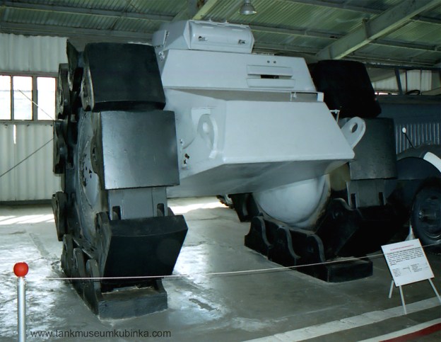
The strange looking Alkett VsKfz 617 (NK-101), preserved at the Kubinka Tank Museum. Note the small slit in the armor for the driver’s view. The small structure in front of the driver’s window was a position indicator for the rear wheel.  (Kubinka Tank Museum image)

Built in the Alkett factory near Berlin, the VsKfz 617 Minenräumer was heavily armored and designed to detonate mines by simply rolling over them. (VsKfz is short for Versuchs Kraftfahrzeug, meaning “test vehicle.”) The three-wheeled vehicle’s wide track was designed to clear a mine-free path for other vehicles to safely travel. The sole prototype carried the Alkett chassis number of 9537 and was registered as NK-101. Unfortunately, much solid information on this vehicle has been lost to history.

The Alkett VsKfz 617 had two large main power wheels at its front. A smaller, caster-style rear wheel was used for turning. Via power take offs and clutches, turning the steering wheel engaged worm shafts on both sides of the hull. The worm shafts operated in opposite directions—one side drew in a chain while the other slackened a separate chain. The chains extended through the VsKfz 617’s hull and were connected to each side of the rear wheel, rotating it as the driver turned the steering wheel. There is no indication that any differential steering was available.

Alkett VsKfz 617 NK-101 side

The rear wheel of the VsKfz 617 digging into the ground can be seen in this image. Note the large shoes of the main wheel.

Each wheel was made up of 10 links and 10 thick, heavy, solid shoes. The pin that connected two links also attached a shoe. Three of the shoes would come together on the ground for each wheel. The total of nine shoes gave the VsKfz 617 ample ground contact. The thick shoes were also resistant to damage from mine blasts. Damaged individual shoes and links could be easily replaced.

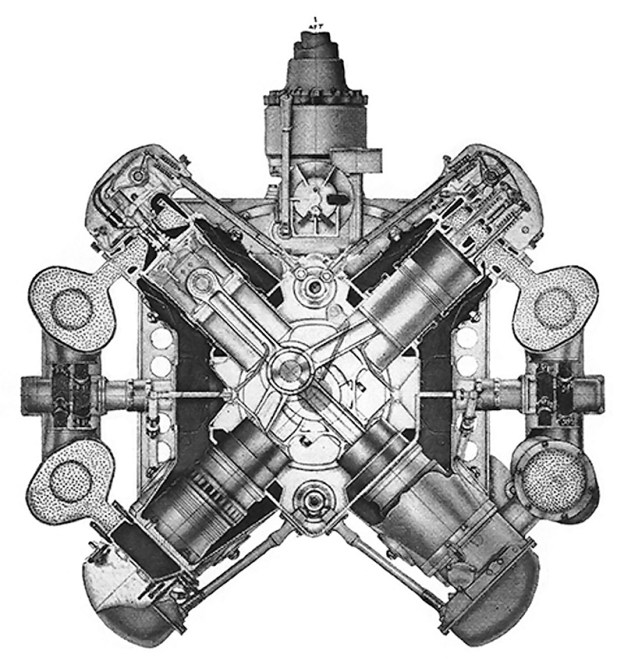
The VsKfz 617’s transmission was positioned in middle of the vehicle. A shaft led from each side of the transmission and engaged the gearing for the main wheels. A Maybach HL-120 V-12 engine was situated transversely behind the transmission. This gasoline engine produced 300 hp (224 kW) from its 4.13 in (105 mm) bore and 4.53 (115 mm) stroke cylinders. Its total displacement was 729 cu in (11.9 L). Two radiators were positioned behind the engine. Cooling air was brought in from ducts on the upper middle of the VsKfz 617 and expelled through vents on its upper rear. A 190 gallon (720 L) fuel tank was positioned above the rear wheel.

Alkett VsKfz 617 NK-101 front

This poor quality image of the VsKfz 617 still conveys the vehicle’s rather imposing appearance. Only one machine gun is in the turret, which is how it was found by Russian forces.

The VsKfz 617’s hull had about 39 in (1 m) of ground clearance that helped protect the crew from mine detonations. Furthermore, the bottom of the vehicle’s hull consisted of 1.58 in (40 mm) thick armor plating, with an additional 0.79 in (20 mm) of armor sheeting inside—creating a double hull. The rest of the vehicle’s hull thickness varied from 0.39 to 1.58 in (10 to 40 mm).

For defensive armament, the VsKfz 617 prototype had a Panzer I turret with two 7.92 mm MG 34 machine guns. However, the production version would have a Panzer II turret with a single 20 mm KwK 30 L/55 cannon and one MG 34 machine gun. The driver occupied the left side of the vehicle and saw out via a small slit in the upper armor. A rear wheel position indicator was just in front of the driver’s view. The vehicle’s commander was on the right, operating the turret. The VsKfz 617 was 20.6 ft (6.28 m) long, 10.6 ft (3.22 m) wide, and 9.5 ft (2.90 m) tall. It weighed 55 tons (50 tonne).

Alkett VsKfz 617 NK-101

This view of the VsKfz 617 displays its unique side profile.

Testing of the VsKfz 617 started as soon as it was completed in 1942. It was quickly found that the VsKfz 617’s method for steering was unsatisfactory and that the vehicle was slow and hard to handle. To make matters worse, its immense weight caused the vehicle to easily get bogged down. The VsKfz 617 and plans for its manufacture were abandoned after the tests.

The sole VsKfz 617 was captured by the Russians in late World War II, possibly in April 1945. The vehicle was inspected and tested in Kubinka near Moscow in early 1947. The Russians came to the same conclusions as the Germans regarding the VsKfz 617’s use, also finding that its slow speed and lack of maneuverability would make it an easy target for artillery. The VsKfz 617 was preserved and is currently on display in the Kubinka Tank Museum.

Alkett VsKfz 617 NK-101 Kubinka rear

The Alkett VsKfz 617 (NK-101) Minenräumer on display in the German pavilion of the Kubinka Tank Museum. Note the steering chain passing through the hull. The scoops on the top of the vehicle are the cooling air exits from the radiators. (Kubinka Tank Museum image)

Sources:
http://ww2history.ru/3909-nemeckijj-minnyjj-tral-minenraumer.-nemeckie.html
http://www.rumaniamilitary.ro/enciclopedia-armelor-roboti-terestrii-in-ww-ii-2
http://www.taringa.net/posts/apuntes-y-monografias/14137217/Vehiculos-extranos-2gm-Kfz-617-MINENR-UMER.html
http://strangevehicles.greyfalcon.us/Alkett.htm
http://www.tankmuseumkubinka.com/?cat=3

GM EM 16-184 x section

General Motors / Electro-Motive 16-184 Diesel Engine

By William Pearce

GM EM 16-184 maintenance

This image shows an Electro-Motive-built 16-184A engine (since the triangular access ports have flanges around them). The top of the cylinder barrels, each with four exhaust valves, can be seen in the middle cylinder bank. The engine’s coolant manifolds are still in place. Note the two water pumps.

In 1937, the United States Navy visited the General Motors Research Laboratories (GMRL) in Detroit, Michigan. Since 1934, GMRL had been involved in experimental, single-cylinder testing of a new light-weight diesel engine. The Navy was interested in a light and powerful diesel and contracted GMRL to develop an engine that would produce 1,200 hp (895 kW). With an output of around 75 hp (56 kW) per cylinder, an engine with 16 cylinders would be needed. However, a V-16 would be too long and too heavy. Led by Charles Kettering, the GMRL designed the unique 16-184 engine to meet the Navy’s needs. The 16-184 engine designation stood for 16 cylinders, with each displacing 184 cu in (3.0 L).

The two-stroke 16-184 diesel had four banks of four cylinders situated at 90 degrees around the crankshaft. A unique feature of the engine was its vertical configuration in which the rows of cylinders were stacked above one another. Because of the stacked cylinder arrangement, this engine configuration was called a “pancake.” A centrifugal blower to feed air into the cylinders sat on top of the engine, and the engine was mounted on top of its right angle gear reduction for the propeller shaft. The 2 to 1 gear reduction was achieved by a pinion on the end of the crankshaft engaging a ring gear mounted on the propeller shaft. No reversing gear was incorporated, because the engine was used in conjunction with variable-pitch propellers.

The 16-184’s crankcase was constructed of steel plates welded together to form a single structure. It was built-up of four “X” elements, each consisting of four cylinders. A static strength report on two of the crankcases noted that they were “…truly remarkable pieces of engineering, and they will well repay careful study by anyone whose work involves mechanical design, welding design, welding techniques and weight saving.

GM 16-184 crankcase

This image of a General Motors 16-184 crankcase undergoing a stress test reveals many unique aspects of the engine. An exhaust housing has been installed on the upper cylinder bank. The top of the engine is on the left side. The intake passageway can be seen in the upper Vee. The camshaft housing can be seen in the lower Vee. The cylinder liners are not installed. Note that the triangular access ports do not have flanges, making this a General Motors-built crankcase.

The crankshaft was supported in and attached to the crankcase by four main bearing carriers and the timing gear housing at the top of the engine. The connecting rods were of the slipper type, which allowed for equal articulation for each cylinder’s rod and reduced the load on the individual crankpins. Each forged-steel piston was attached to its connecting rod by two trunnions positioned on either side of the connecting rod and bolted to the piston.

The blower on the top of the engine fed air into two crankcase passageways on opposite sides of the engine. The blower spun at ten times crankshaft speed and delivered around 4,000 cu ft (113.27 cu m) of air per minute at 6 psi (0.4 bar). The air flowed through ports in each cylinder barrel that were uncovered by the piston. The top of the cylinder barrel was enclosed by a housing for the fuel injector (at center) and four exhaust valves (surrounding the fuel injector). This housing made up the cylinder’s combustion chamber. The exhaust valves opened into a space above the cylinders where exhaust flowed into an exhaust manifold. The exhaust manifold was positioned in the engine’s Vee and above the intake passageway. The cylinders used uniflow scavenging, in which fresh air would flow through the intake ports in the lower cylinder barrel and push the exhaust gases out the open valves at the top of the cylinder.

GM EM 16-184 x section

A sectioned view of one of the 16-184 X cylinder groups. The propeller shaft drive is at the top of the image. Note the camshaft in the upper and lower Vees. The dark areas in the left and right Vees are the intake air passageways. The cylinder ports can be seen in the lower left cylinder.

Two camshafts were geared to the crankshaft via an idler gear in the timing gear housing at the top of the engine. One camshaft was situated in each non-intake/exhaust engine Vee. The camshafts controlled three pushrods for each cylinder via roller cam followers. One pushrod controlled the fuel injector while the other pushrods each controlled two exhaust valves. The pushrods articulated rocker arms that were bolted to the top of a cast iron exhaust housing attached over each cylinder bank. The top of the cylinder barrel assembly passed through the exhaust housing. This configuration allowed exhaust gases from the cylinder to be collected by the exhaust housing and delivered to the exhaust manifold via three ports for each cylinder.

Each piston was cooled by a jet of oil impinging on its underside. Two centrifugal water pumps were driven by the lower accessory section. The upper pump circulated coolant through each exhaust housing. The upper part of the cylinder barrel had a welded sheet metal water jacket. Via a special connection, coolant flowed from the exhaust housing into the cylinder barrel water jacket. The lower pump circulated sea water through the jacketed exhaust manifolds.

The 16-184 engine had a 6.0 in (152 mm) bore and 6.5 in (165 mm) stroke, giving a total displacement of 2,941 cu in (48.2 L). The complete engine was roughly 11 ft (3.4 m) tall, 4 ft (1.2 m) wide, and weighed 4,800 lb (2,177 kg). The 16-184 developed 1,200 hp (895 kW) at 1,800 rpm.

GM EM 16-184 installed

This view of an installed 16-184A engine shows the three pushrods for each cylinder. The middle pushrod controlled the fuel injector. Note the pedal and lever in the Vee. The pedal engaged a clutch and the lever connected the engine to or disconnected the engine from the propeller shaft.

By 1938, single cylinder test engines were operating reliably and achieving the design goals necessary for a complete, 1,200 hp (895 kW) engine. The design for the complete 16-cylinder engine had been completed and prototype construction was underway. The 16-184 was first run in June 1939, and it completed the Navy’s 168-hour endurance test on 31 October 1940. In 1941, two test engines were installed in an experimental submarine chaser: USS PC-453 designed by Captain A. Loring Swasey. PC-453 served as the prototype for a class of wooden submarine chasers during World War II. The boat was re-designated SC-453 and transferred to the Coast Guard after the war.

In 1941, 16-184 engine production was undertaken by the Electro-Motive Division of General Motors. Electro-Motive originally produced railcars and was purchased by General Motors in 1930 as the latter looked to expand into the diesel engine and rail marketplaces. The production engines built by Electro-Motive were designated 16-184A and had some minor changes to their crankcases, including welded-in cylinder liners where the prototype’s were screwed-in. In addition, triangular access ports on the General Motors 16-184 crankcase did not have flanges, while the Electro-Motive 16-184A crankcase did. The Electro-Motive 16-184A engines were built in La Grange, Illinois, and the first engine started test runs on 11 October 1941. The Navy accepted the first 16-184A engine on 5 February 1942.

Two pancake engines were installed in each of the 253 110-foot (33.5 m) submarine chasers built during World War II. After the war, several of these boats were sold to other nations. The 16-184A engines were noted for their reliable operation and good service life. Some of these engines continued to operate (occasionally) into the year 2000. Approximately 544 16-184A engines were built.

GM 16-338

This image shows the intake side of the General Motors 16-338 engine installed on its generating unit. This arrangement led to issues, for any liquids that leaked from the engine would drain down into the generator.

The 16-184A engine design was used as the basis for the General Motors 16-338 engine built in the late 1940s. The 16-338 had the same bore and stroke as the 16-184A and produced 1,000 hp (746 kW) at 1,600 rpm. Four 16-338 engines were installed in the Tench- and Tang-class submarines, and two were installed in the USS Albacore—the Navy’s first “teardrop” hull submarine, which paved the way for modern sub design.

The 16-338 engines sat atop a generator to provide power to electric motors that drove the ship’s propellers. The engine also had a different intake and exhaust arrangement in which the manifolds were situated in separate Vees of the engine. The 16-338 engines proved somewhat unreliable in service and required excessive maintenance. Some of the 16-338’s issues were due to the Navy using standard diesel lubricating oil rather than the special oil specified for use in the engine. Ultimately, the Tench- and Tang-class submarines were re-engined and their 16-338 parts were used as spares to keep the USS Albacore running until it was withdrawn from service in 1972.

Sources:
– “Development of a Light Weight Diesel Engine” by J. C. Fetters, Diesel Power & Diesel Transportation (August 1942)
Parts Book GM Diesel Engine, Model 16-184A by Electro-Motive Division (1944)
Static Strength Tests of Diesel Engine Crankcases GMC 16-184 and EMC 16-184-A for 110-Foot Patrol Boats by J. W. Day (August 1943)
Diesel War Power by Electro-Motive Division, General Motors (1944)
Engines Afloat Volume II by Stan Grayson (1999)
http://usautoindustryworldwartwo.com/General%20Motors/electro-motive.htm
http://en.wikipedia.org/wiki/Electro-Motive_Diesel
http://www.navsource.org/archives/12/150453.htm
http://www.ss563.org/t-class.html
http://nonplused.org/panos/uss_albacore/12/engine_01.html