Boeing-XF8B-BuNo-57984-in-flight

Boeing XF8B Five-In-One Fighter

By William Pearce

In 1942, experience in the Pacific War made the United States Navy aware that their carrier-based fighter aircraft lacked the range needed to properly escort other aircraft while the home carrier stayed outside the combat radius of enemy aircraft. In addition, long-range ship-borne aircraft were needed to take the fight to the Japanese mainland. This prompted the Navy to search for a long-range, carrier-based fighter. The Boeing Airplane Company responded with its Model 400 design, which interested the Navy, and a contract for three prototypes was issued on 10 April 1943. The new aircraft was designated the Boeing XF8B.

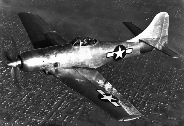
Boeing-XF8B-BuNo-57984-in-flight

The first XF8B (BuNo 57984) on a test flight along with a piggyback flight engineer hunched over behind the pilot. Note the two separate exhaust stacks in the cowling and the four stacks behind the cowling.

From the start, Boeing had sought an agreement with the Navy in which Boeing would be given almost full control of the project and would develop the aircraft as they thought best. Part of the reason for this request was that the buyer, whether Navy or Army Air Force, had a habit of constantly issuing minor changes which often resulted in some developmental chaos on the part of the aircraft manufacturer. The Navy had already issued specifications for the XF8B, which included a top speed of 342 mph (550 km/h), a minimum speed of 79 mph (127 km/h), a takeoff distance with a 25-knot (29 mph / 46 km/h) headwind of 262 ft (80 m), an initial climb rate of 3,760 fpm (19.1 m/s), and a ceiling of 30,000 ft (9,144 m). Since Boeing had agreed to these specifications, the Navy felt that Boeing’s interest to develop the aircraft with little interference was in good faith and begrudgingly consented to Boeing’s request.

The Boeing XF8B was an all-metal monoplane with a conventional layout. What was less conventional about the XF8B was its Pratt & Whitney R-4360 28-cylinder engine with contra-rotating propellers, its large size, the inclusion of an internal bomb bay, and Boeing’s intention for the aircraft to be more than just a long-range fighter but also to be used as an interceptor, level bomber, dive bomber, and torpedo bomber. The multi-role characteristic of the XF8B led Boeing to refer to it as the “Five-In-One” aircraft.

A mock-up of the XF8B was completed in September 1943 and was inspected by the Navy in early October. The design of the aircraft was finalized on 7 October 1943. The XF8B’s fuselage had flat sides with an arched top and a relatively flat bottom. It was formed by aluminum panels riveted to aluminum formers and longerons. The cockpit was above the wing’s trailing edge and enclosed in a rearward sliding bubble canopy. The control stick moved fore and aft like normal, but left and right movement was limited by a pivot point to the upper half of the stick. This design was adopted to save space in the cockpit. The pilot was protected by armored glass and an armor plate in front of the cockpit and an armored seat. A 40 US gal (33 Imp gal / 151 L) oil tank was positioned forward of the cockpit. Below the cockpit was a bomb bay that could accommodate up to 3,200 lb (1,451 kg) of ordnance. However, the bomb bay’s size limited what could be carried to four 250 or 500 lb (113 or 227 kg) bombs or two 1,000 or 1,600 lb (454 or 726 kg) bombs. One 2,000 lb (907 kg) bomb could also be accommodated. For long range flight, a 270 US gal (225 Imp gal / 1,022 L) fuel cell could be installed in the bomb bay. Two snap-opening doors enclosed the bomb bay and would automatically open and close during bomb release. The doors could open or close in under one second. At the rear of the fuselage was a fully-retractable tail wheel.

Boeing-XF8B-BuNo-57984-flaps

Taken before the aircraft’s first flight, this image shows the XF8B’s large flaps that extended back some 32 in (.813 mm) as they were deployed. The door in front of the cockpit was the air exit for the oil cooler. The hangar in the background was camouflaged to look like a building during World War II.

The aircraft’s wing was designed for +7gs and used a single spar. On the forward half of the wing, the aluminum skin was rivetted to the wing’s internal ribs and spot welded to the stringers. The rest of the wing used rivets. Each wing housed 192 US gal (160 Imp gal / 727 L) of fuel in three tanks: a 100 US gal (83 Imp gal / 379 L) tank between the fuselage and landing gear, a 42 US gal (35 Imp gal / 159 L) tank between the landing gear and gun bay, and a 50 US gal (42 Imp gal / 190 L) tank between the gun bay and wing fold. The main landing gear retracted to the rear with the tire rotating 90-degrees to lay flat in the wing. This gear retraction method was developed by Boeing in the early 1930s and licensed to Curtiss for the P-36 Hawk and P-40 Warhawk. When retracted, the gear strut was concealed by doors that joined a cover attached to the upper part of the wheel. The main gear had a track of 13 ft 4 in (4.06 m). The gun bay of each wing could accommodate three .50-cal machine guns with 400 rpg or three 20 mm cannons with 200 rpg. The armament could be mixed, but the 20 mm cannons would need to be outboard of the .50-cal machine guns because of clearance issues. The mounts used by Boeing to accommodate both the .50-cal machine guns and 20 mm cannons were designed by Vought for the XF5U Flying Flapjack. The outer 12 ft 4 in (3.76 m) of each wing folded up for storage on an aircraft carrier. Wing folding was controlled by electric motors and could only be accomplished after the wings were unlocked by one cockpit control, followed by engaging a covered switch. The wings would still not fold unless there was weight on the landing gear.

Large fowler flaps spanned the wing trailing edges from the fuselage to 20 in (508 mm) beyond the wing-fold point. The 20 in (508 mm) section of flap past the wing fold could be manually folded down 180-degrees. The flaps were powered by an electric motor and extended back approximately 32 in (.813 mm) and down to 35 degrees. The flaps would automatically retract when airspeed reached 150 mph (241 km/h) and automatically redeploy to the selected position when airspeed dropped to 120 mph (193 km/h). This was a safety feature to lessen the carrier pilot’s workload during a wave-off. The aileron occupied the rest of the wing’s trailing edge from the flap to the tip. The ailerons used booster tabs to lessen the input needed by the pilot. A hardpoint under each wing between the main gear and the fuselage could accommodate a bomb up to 1,600 lb (726 kg) or a 150 US gal (125 Imp gal / 568 L) drop tank. A hardpoint on the aircraft’s centerline would accommodate a torpedo and render the bomb bay inoperative, but it is not clear if such accommodations were ever made. In addition, later proposals included using the two wing hardpoints for torpedoes. There was also the capacity for eight rockets under the outer section of each wing.
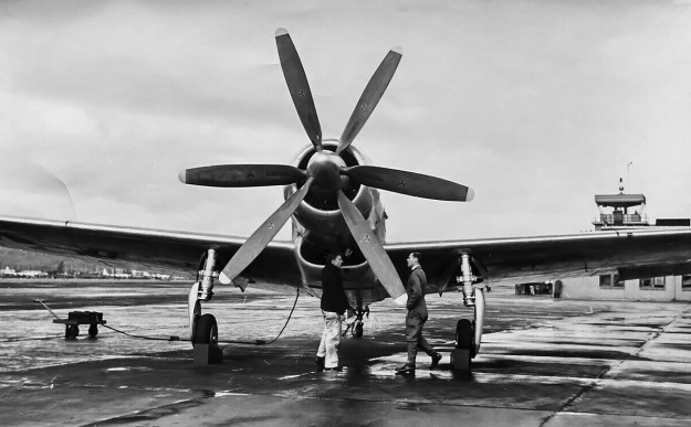
Boeing-XF8B-BuNo-57984

Test pilot Robert Lamson (right) and a crewman give scale to the very large size of the XF8B aircraft. Note that the machine guns were not initially installed in the first aircraft. The scoop under the cowling brought in air for the carburetor, intercooler, and oil coolers.

Like the rest of the aircraft, the XF8B’s tail was of all metal construction. The vertical stabilizer resembled that of the Boeing B-17 Flying Fortress and B-29 Superfortress. The rudder and elevators had balance tabs designed to maintain a constant force on the control surface. Under the tail was a tailhook that retracted flush with the belly of the aircraft.

At the front of the aircraft was the R-4360-10 engine enclosed in an elegant and fairly tight-fitting cowling. The R-4360-10 had a two-stage supercharger and produced 3,000 hp (2,237 kW) at 2,700 rpm. The first (auxiliary) stage was a large blower attached to the extreme rear of the engine and driven via a variable-speed fluid coupling. The second (main) stage had two speeds and was in the conventional supercharger housing between the carburetor and crankcase. The engine turned a six-blade, contra-rotating Aeroproducts propeller that was 13 ft 6 in (4.11 m) in diameter. This was basically the same engine and propeller combination used on the Republic XP-72, the difference being the XP-72 used a remote first (auxiliary) stage supercharger driven by a long shaft.

Engine cooling air was brought in the front of the cowling and expelled via cowl flaps around the upper part of the fuselage and slits for the exhaust stacks on the sides of the aircraft. The engine’s exhaust system was rather unusual and consisted of 14 exhaust stacks, with each stack serving two cylinders. On each side of the aircraft, four exhaust stacks were located in a slit behind the cowling. Another exhaust stack was forward of the slit and under the cowl flaps, and another stack protruded from the cowling forward of the cowl flaps. The last two stacks traveled through a passageway at the center of the scoop under the aircraft and expelled exhaust out of the bottom of the scoop.

Boeing-XF8B-BuNo-57984-gear

The XF8B shortly after takeoff with a good view of the gear as it retracts. The doors close over the struts and meet the covers attached to the main wheels. Also just visible are the exhaust stacks in the bottom center of the scoop.

The scoop under the aircraft and just behind the cowling took in air for the carburetor, intercooler, and oil coolers via a complicated airbox. Induction air was fed from the airbox and into the auxiliary supercharger. After being pressurized, the air was fed back through an air-to-air intercooler housed in the airbox and then to the carburetor (and into the main supercharger). Air used to cool the intercooler was discharged via an exit flap forward of the bomb bay. An oil cooler was positioned on each side of the aircraft to the rear of the cowling. After passing through the airbox, cooling air was directed through the oil coolers and out exit doors on the upper sides of the fuselage, just forward of the cockpit.

The Boeing XF8B had a wingspan of 54 ft (16.46 m) and length of 43 ft 2 in (13.16 m). Its height was 12 ft 9 in (3.89 m) with the propellers down, 16 ft 3 in (4.95 m) with the propellers up, and 15 ft 10 in (4.83 m) with the wings folded. However, folding the wings required 20 ft (6.10 m) of vertical clearance. With the wings folded, the aircraft was 29 ft 4 in wide (8.94 m). The XF8B had a maximum speed of 432 mph (695 km/h) at 23,200 ft (7,071 m), 412 mph (663 km/h) at 14,500 ft (4,420 m), and 375 mph (604 km/h) at sea level. Takeoff distance with a 25-knot (29 mph / 46 km/h) headwind was 261 ft (80 m), and takeoff distance in still air with 35-degrees of flaps was 550 ft (168 m). The aircraft’s initial rate of climb was 3,110 fpm (15.8 m/s), and its service ceiling was 37,500 ft (11,430 m). The XF8B’s maximum range was 2,300 miles (3,701 km) at 225 mph (362 km/h) and 15,000 ft (4,572 m). This was with 384 US gal (320 Imp gal / 1,454 L) of fuel in the wing tanks, 270 US gal (225 Imp gal / 1,022 L) of fuel in the bomb bay, and 300 US gal (250 Imp gal / 1,136 L) of fuel in two drop tanks, for a total of 954 US gal (794 Imp gal / 3,611 L) of fuel. The aircraft had an empty weight of 14,100 lb (6,396 kg), a gross weight of 20,508 lb (9,302 kg), and a maximum weight of 22,960 lb (10,414 kg). Takeoff distance at 22,960 lb (10,414 kg) was 1,100 ft (335 m). It was believed that if the R-4360’s output were increased to 3,600 hp (2,685 kW), the XF8B could achieve 450 mph (724 km/h).

For a fighter comparison, the XF8B’s wingspan was 14 ft (4.27 m) more than a Republic P-47 Thunderbolt, and its empty weight was 2,000 lb (907 kg) more than the maximum gross weight of a North American P-51 Mustang. Overall, the XF8B was roughly the same size as a Grumman TBF/TBM Avenger but weighed 3,500 lb (1,588 kg) more.
Boeing-XF8B-BuNo-57984-in-flight-left

Lamson and probably Bud Zerega on a test flight in the first aircraft now fitted with machine guns. The aircraft stayed bare metal until mid-1946.

The XF8B program at Boeing was overseen by Wellwod E. Beall and Richard L. Stith, with Lyle A. Wood as the head engineer for most of the project. Although missing some components, a mock-up was inspected by the Navy in early October 1943. The Navy did not care for the bomb bay but was ultimately convinced by Boeing to keep it. The aircraft was built at Boeing Field in Seattle, Washington. Delays were experienced with the engine and propellers, but the first XF8B (BuNo 57984) was finished in late October 1944. The aircraft was left bare metal, and it was first run on 2 November 1944. Ground runs and taxi tests revealed a number of minor issues that were quickly fixed. The aircraft’s first flight occurred on 27 November 1944 and was piloted by Robert T. Lamson. The XF8B performed well during initial flight tests but aileron control was heavy.

The single-seat fighter was modified with a jump seat behind the pilot for a flight engineer. On 26 December 1944, Bud Zerega became the first XF8B “passenger,” carried aloft hunched over in the back of the cockpit. The second XF8B (BuNo 57985) was painted Navy Sea Blue and was completed on 31 January 1945. However, the aircraft was rolled off to the side to await delivery of its engine and propeller, which were very behind schedule. By this time, the Navy had begun to think the XF8B would be better suited as an attacker than a long-range fighter or any other role Boeing had envisioned.

On 13 February 1945, the first XF8B suffered a gear collapse during a high-speed taxi test. The aircraft was only lightly damaged, but the contra-rotating propellers were completely destroyed as the front blades were bent back into the rear blades. The cause of the accident was a faulty microswitch commanding the gear to retract. An anti-squat switch overrode that command because of the weight on the main gear, but as the taxi test was conducted, the wings generated lift and took weight off the main gear, enabling the faulty microswitch to retract the gear. The engine was replaced, and the aircraft was repaired in 19 days.

Boeing-XF8B-BuNo-57986-tanks-Eglin

The second XF8B (BuNo 57985) with 150 US gal (125 Imp gal / 568 L) drop tanks delivered to the Army Air Force. This was the only aircraft with the tall canopy and blue spinner.

In March 1945, the XF8B was flown to the Naval Air Station at Patuxent River in Maryland. Here, the aircraft was evaluated by 31 pilots in 21 days. The overall impression was positive, although the aircraft’s brakes were noted as being weak and its ailerons heavy. The XF8B was then flown to Anacostia Naval Air Station near Washington, DC where another 10 pilots flew the aircraft over two days in early April. The first XF8B returned to Seattle on 9 April 1945. Flight testing continued until the aircraft was grounded in mid-August due to an issue with the engine’s gear reduction. While awaiting a new engine, the XF8B’s aileron control system was rebuilt to improve control, and the aircraft returned to the air on 22 October 1945.

After waiting nearly a year, the second XF8B (BuNo 57985) finally received its R-4360 engine and made its first flight on 27 November 1945, exactly one year after the first aircraft. By 26 December 1945, the aircraft had accumulated just over 11 hours when a stuck intake valve caused the engine to only produce idle power. Lamson was flying the aircraft at the time and decided to land at the nearest field, Everett Airport (not the current Paine Field). Everett Airport was also known as Ebey Island Airport and Snohomish County Airport, but it was often referred to as Marysville. It was a grass strip located on an island between Everett and Marysville. After the heavy XF8B touched down on the water-logged grass, the main gear sunk in, and the aircraft went up on its nose. The propellers were ruined again, but the rest of the aircraft had very little damaged. After three weeks of repairs, the second XF8B was flown back to Boeing Field.

Boeing-XF8B-BuNo-57984-in-flight-blue

XF8B BuNo 57984 now painted Navy Sea Blue with Lamson at the controls. Note the newly installed streamlined canopy. Reportedly, only the second aircraft (57985) was fitted with dive recovery flaps. However, there appear to be dive recovery flaps just aft of the gun ejection ports. The XF8B may have been the only aircraft to carry two different “Boeing” logos simultaneously (1930s Boeing airplane logo on the tail and 1940s Boeing script on the cowling).

On 13 February 1946, the second XF8B was flown to Wright Field, Ohio to be evaluated by the Army Air Force (AAF). The AAF had shown an interest in the XF8B, and the Navy agreed to sign the second aircraft over. A number of modifications were incorporated into BuNo 57985 at the direction of the AAF, including the addition of a dive recovery flap fitted outboard of the main gear wheel well. AAF evaluation continued until 3 April 1946, when an engine failure brought an end to the tests. The cause of the engine trouble was the failure of the second (main) stage supercharger drive.

The Third XF8B (BuNo 57986) made its first flight in March 1946. It did not incorporate the changes made to BuNo 57985 for the AAF, but it replaced the second aircraft for flying duties with the AAF. The aircraft was completed with a more streamlined canopy that was intended for all XF8B aircraft. In July 1946, BuNo 57986 was flown to Eglin Air Force Base in Florida to complete armament tests intended for BuNo 57985. The third XF8B was the only one to fire its guns in the air and drop bombs, even if they were just dummy bombs. Only .50-cal guns were tested, and they were fairly accurate. During one test, a ricochet broke the canopy, parts of which flew back and damaged the horizontal stabilizer. A gun blast tube failed in another test, resulting in that gun not being used for subsequent tests.

Problems with bombs included getting the bomb bay doors to open at higher speeds as well as the released bomb coming in contact with the quick doors as they closed. Also, the thin fins on bombs carried externally were prone to cracking due to the XF8B’s long flight duration and relatively high speed. The AAF tests concluded in December 1946, and they found the aircraft to be unsuitable as a dive bomber, due to longitudinal instability, and inferior as a fighter, due to its large size and slower maneuverability. At one point, the AAF had compared the XF8B to the XP-72, which seems like an unfair comparison given the different philosophies that went into the designs of the respective aircraft (multi-role vs all-out interceptor). The AAF felt that the XF8B was a satisfactory attacker and low-level bomber, but other aircraft adequately covered those roles.

Boeing-XF8B-BuNo-57986-side

The third XF8B (BuNo 57986) was completed with the streamlined canopy. Seen at Boing Field, the aircraft was delivered to the AAF to take the place of the second aircraft.

A new engine was installed in the first XF8B; a new streamlined canopy replaced the taller version, and it was painted Navy Sea Blue, like the two other aircraft. It was accepted by the Navy on 15 October 1946. The second aircraft was also fitted with a new engine, and it was accepted by the Navy on 5 November 1946. Following its time with the AAF, the third aircraft was accepted by the Navy on 1 August 1947.

The Navy’s opinion of the XF8B was similar to that of the AAF: the war was over and current aircraft were filling the various roles intended for the XF8B. On a crowded carrier deck, the large size of the XF8B meant that only half the number of aircraft could be accommodated compared to the Grumman F6F Hellcat and Vought F4U Corsair. While it was a good multirole aircraft, it did not particularly excel at any of the roles; it was a jack of all trades and a master of none. By some accounts, the Navy had reached out to Boeing in the spring of 1946 regarding a contract for 600 aircraft as torpedo bombers. The XF8B’s performance specifications combined with its ability to carry three torpedoes made the aircraft an attractive option. However, the managers at Boeing who fielded the Navy’s request were focused on B-29 production and turned it down.

In the end, the XF8B program cost twice the estimate, and the plane was 1,400 lb (635 kg) overweight. In addition, numerous delays were encountered that were sometimes the result of Boeing’s actions and sometimes the result of engine and propeller delivery issues. All three XF8Bs were eventually stored at the Naval Air Material Command in Philadelphia, Pennsylvania. BuNos 57984 and 57985 were struck off charge on 31 January 1948, and BuNo 57986 was struck off on 16 March 1950. Lamson attempted to purchase one of the XF8Bs, but the Navy refused, and all were scrapped.

Boeing-XF8B-BuNo-57986-PA

XF8B BuNo 57986 sits in Philadelphia awaiting its day with the scrapper. The flap section that extended into the wing fold and the place it occupied in the folded wing can both be seen.

Sources:
Boeing XF8B-1 Five-In-One Fighter by Rick Koehnen (2005)
The Boeing XF8B-1 Fighter: Last of the Line by Jared A Zichek (2007)
U.S. Experimental & Prototype Aircraft Projects, Fighters 1939–1945 by Bill Norton (2008)
R-4360 Pratt & Whitney’s Major Miracle by Graham White (2006)

Breton-Rotary-Engine-1909

Breton Rotary Aircraft Engine

By William Pearce

On 25 February 1909, René Breton filed a French patent application for an internal combustion engine of a new configuration. For his design, Breton was awarded French patent 399,918 on 8 May 1909, and the patent was published on 10 July 1909. Breton was subsequently awarded British patent 4782 on 27 October 1910 and US patent 982,468 on 24 January 1911.

Breton-Rotary-engine

Sectional drawing from the Breton rotary engine patent. The three 160-degree Vee engine sections are visible, as are their crank disks. Planetary gears on the crank disk shafts meshed with a sun gear on the fixed central shaft and rotated the engine.

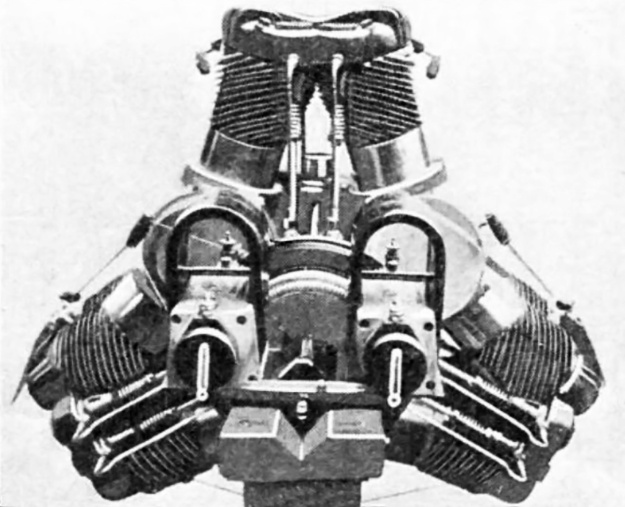
In his patent, Breton outlined a 12-cylinder, air-cooled, rotary aircraft engine designed to be compact and very light. The engine had a front and rear cylinder row, each with six cylinders. The cylinders of each row were arranged around the engine in three two-cylinder groups, with each two-cylinder group positioned 120 degrees around the center of the engine. Each two-cylinder group formed a 160-degree Vee twin. The front and rear rows were mirrored so that a front two-cylinder group matched with a rear two-cylinder group. Each front and rear cylinder was paired, fired simultaneously, and shared a common combustion chamber. The intake valve was on the rear side of the rear cylinder, and the exhaust valve was on the front side of the front cylinder.

The pistons of each two-cylinder, 160-degree Vee group were attached to a “crank disk” with fork-and-blade connecting rods. Each crank disk was built up from a shaft that ran on ball bearings and had a planet gear keyed at its center. The planet gear was sandwiched between the inner ends of front and rear disks, onto which the respective connecting rods were mounted. A front and rear outer disk closed out the basic assembly. The planet gears of the three crank disks engaged a sun gear mounted to a shaft at the center of the engine. Being a rotary engine, the central shaft was fixed to the airframe, and the engine rotated around the shaft. Each crank disk rotated four times for every revolution around the central shaft. With the propeller fixed to the front of the crankcase, the gearing meant that each four-stroke cylinder would fire twice before one revolution of the propeller/engine was completed.

Breton-Rotary-engine-transverse

Transverse drawing from the Breton rotary engine patent showing the connecting rods of a front and rear cylinder pair attached to the crank disk. At the center of the crank disk is the planetary gear.

Front and rear cam rings were mounted to the fixed central shaft to control the respective exhaust (front) and intake (rear) valves. The cam lobes on the cam ring actuated a lever that acted on a push rod to open the individual valves, each of which was held closed by a spring. The valve levers for the cylinder Vee groups were profiled, and the cam rings could slide on the central shaft. This combination allowed for certain Vee engine groups to be shut down by the cam rings sliding to achieve the desired interaction with the profiled valve levers. When an engine group was shut down, the intake valves were kept closed by the relocated intake cam ring missing the profiled intake lever, and the exhaust valves were kept open via a continuous collar on the relocated exhaust cam ring being in constant contact with the profiled exhaust lever. The cam rings would slide to positions in which they would operate either two, three, four, or six engine groups—respectively enabling either four, six, eight, or twelve cylinders.

As previously mentioned, the combustion chamber was shared by each front and rear cylinder pair. The combustion chamber was of a hemispherical design, but the cylinder head was of a “T” design with the underhead single intake valve and single exhaust valve on their respective sides of the cylinder pair. The patent drawings include a chamber at the rear of the engine that would distribute the air and fuel mixture from a carburetor to each cylinder pair via a manifold, but this induction system was not used on the prototype engine.

Breton-Rotary-engine-sectional

Another transverse drawing from the Breton rotary engine patent illustrating the common combustion chamber of the front and rear cylinder pair. The intake valve is on the left and the exhaust valve on the right. The fixed central shaft and its sun gear are at the center of the drawing. The cam rings are visible on the central shaft. At the bottom of the drawing is a crank disk with its two fans.

A centrifugal fan was mounted to each side of each disk crank assembly. A cover over the front side of each disk crank had a scoop that faced the direction of engine rotation and helped bring air into the fan. Air brought in would circulate through the crankcase and help cool engine’s internal components. The fan on the rear side of each crank disk would force the air out of the crankcase via an outlet that faced away from the direction of engine rotation. The patent proposes that some of the air warmed as it passed through the crankcase would be siphoned off to feed the induction chamber at the rear of the engine.

The prototype engine was very similar to what was described in the patent but differed mainly with the delivery of air and fuel into the cylinders. The internal fans no longer provided induction air, and there was no internal air chamber, carburetor, or intake manifolds. The prototype engine used fuel injection, with a pump for each cylinder pair controlled in a similar way as the valves. The fuel flowed through a line from the crankcase to each intake valve, and whatever injection pressure was present was amplified by the centrifugal action of the engine’s rotation. It appears air was drawn into the cylinder via openings in the intake valve housing.

Breton-Rotary-Engine-1909

The Breton Rotary as displayed at the 1909 Salon de l’aéronautique. Note the four-cylinder head casting and the individual fuel lines. The internal air-cooling exit covers can be seen over the crank disks.

Few details of the prototype engine have been found, but it appears to consist of an aluminum crankcase with steel cylinder barrels. The cooling fins on the cylinder barrels were angled to match the engine’s rotation and to keep the fins parallel to the airflow. With each engine section made up of a 160-degree Vee, the two end pairs of cylinders converged together at a 40-degree angle. A single cast metal head was used to cover the four converging cylinders. A single spark plug was positioned in the center of each cylinder pair. The spark plugs were fired from a magneto attached to the aircraft and powered by a ring gear mounted to the rear of the engine. The rear of the fixed central shaft extended from the engine to provide a mounting point to attach the engine to the airframe.

The Breton rotary engine had a 3.23 in (82 mm) bore and a 3.35 in (85 mm) stroke. Total displacement from its 12 cylinders was 329 cu in (5.39 L). The engine produced 60 hp (45 kW) at 400 rpm, which means the crank disks were each rotating at 1,600 rpm. Sources indicate that the engine produced 20 hp (15 kW) on four cylinders, 30 hp (22 KW) on six cylinders, and 40 hp (30 kW) on eight cylinders. Maximum engine speed was stated as 500 rpm (2,000 rpm for the crank disks). The relatively small engine weighed only 198 lb (90 kg).

The engine made its debut in October 1909 at the Salon de l’aéronautique in Paris and had a selling price of 10,000 Francs. The engine appeared again at the 1910 Salon and was modified with two magnetos in place of the single unit originally fitted. After 1910, no further information has been found regarding the engine or its testing. A photo exists showing the engine in a somewhat neglected state. It is possible that the prototype engine survived (at least into the 1960s) stored in a museum or private collection.

Breton-Rotary-Engine-1910

The Breton engine as seen at the 1910 Salon. This view illustrates the cylinder cooling fin angles to match the engine’s rotation. The engine appears very similar to the 1909 version with the exception of new dual magnetos.

Sources:
– “Explosion-Motor” US patent 982,468 by René Breton (granted 24 January 1911)
– “Flight Engines at Paris Show” Flight (13 November 1909)
– “Aero Engines in the Paris Salon” The Aero (12 October 1909)
Les Moteurs a Pistons Aeronautiques Francais Tome II by Alfred Bodemer and Robert Laugier (1987)

Westland-F7-30-front-left

Westland F.7/30 (PV.4) Biplane Fighter

By William Pearce

On 1 October 1931, the British Air Ministry issued Specification F.7/30 for a single-seat day and night fighter. Further requirements of Specification F.7/30 were for the aircraft to be capable of at least 195 mph (314 km/h) at 15,000 ft (4,572 m), have a landing speed of 50 mph (80 km/h), carry an armament of four machine guns, and offer the pilot an unobstructed, all-around field of view. Aircraft developed from Specification F.7/30 were expected to outperform then-current contemporary fighters in respect to handling, maneuverability, range, rate of climb, and service ceiling.

Westland-F7-30-in-flight

The Westland F.7/30 (PV.4) on an early test flight. The aircraft is seen with its original open canopy and exhaust manifolds. Note the good visibility from the pilot’s position.

Numerous manufacturers responded to Specification F.7/30, including Blackburn with the F.3 biplane, Bristol with the Type 123 biplane and Type 133 monoplane, Gloster with the SS.37 biplane, Hawker with the P.V.3 biplane, Supermarine with the Type 224 monoplane, and Westland with the F.7/30 biplane. In addition to the F.7/30 biplane, Westland also submitted a high-wing monoplane design. However, the monoplane’s long wingspan and comparatively high landing speed resulted in the biplane being selected by the Air Ministry.

Although an engine type was not listed in Specification F.7/30, the Air Ministry informally expressed a strong preference for the Rolls-Royce Goshawk. The Goshawk was a development of the Rolls-Royce Kestrel IV V-12, which was the most advanced British liquid-cooled production engine at the time. While both the Kestrel and the Goshawk had a 5.0 in (127 mm) bore, a 5.5 in (140 mm) stroke, and displaced 1,296 cu in (21 L), the Goshawk employed evaporative (steam) cooling.

Westland-F7-30-front-left

The Westland F.7/30 with an enclosed canopy but still with the original exhaust manifolds. The leading-edge slats are visible on the upper wing.

The basic premise behind evaporative cooling for aircraft engines was that cooling water would enter the engine and be allowed to boil as it flowed through the hottest part of the engine, the cylinder heads. The conversion of water to steam allowed for more heat to be taken from the engine compared to traditional water cooling. The steam would then be fed though a condenser (heat exchanger), in which the steam would cool and convert back to water. The condenser could be incorporated into the aircraft’s structure, such as the wing’s leading edge and skin, and the condenser would be cooled by the slipstream of air flowing over its surface. In theory, the end result of evaporative cooling compared to conventional water cooling was a more efficient system that eliminated the drag of a conventional radiator. In practice (with various installations), evaporative cooling systems were complex, leaked steam, had inefficient or ineffective condensers, and could suffer from vapor lock.

The Westland F.7/30 originally carried the company designation PV.4, and it was designed by Arthur Davenport, Westland’s chief designer, with input from Harald Penrose, Westland’s chief test pilot. Most of the aircraft designed for Specification F.7/30 were fairly conventional. However, the Westland F.7/30 incorporated some unconventional features. A biplane arrangement was selected to satisfy the 50-mph (80-km/h) landing speed and maneuverability requirements of Specification F.7/30. The cockpit was placed in the extreme nose of the aircraft and forward of the upper wing to provide an unobstructed view for the pilot. This necessitated moving the engine from the nose of the aircraft to behind the cockpit, with an extension shaft driving the propeller.

The aircraft’s center and forward fuselage had a tubular aluminum frame and were covered by removable aluminum panels. The rear fuselage and tail had an aluminum frame and were cover by fabric. The upper and lower wings attached to the center fuselage, which was strengthened to support the engine. The upper wing was of the gull-type to improve the pilot visibility and was equipped with ailerons and automatic leading-edge slats. A 49 US gal (41 Imp gal / 186 L) fuel tank was located in the inboard section of each upper wing. The lower wing was staggered behind the upper wing, had a reduced span, and was straight with no control surfaces. Both upper and lower wings had aluminum frames with aluminum skin covering the leading edge and fabric covering the rest of the wing. All control surfaces had fabric-covered aluminum frames.

Westland-F7-30-side

Side view of the Westland F.7/30 with the updated exhaust manifolds. Note the barrel of the upper machine gun extending almost to the propeller, while the lower machine gun was almost completely recessed. The odd structure forward of the canopy is the gun sight.

The Goshawk II engine produced 600 hp (447 kW) at 2,600 rpm and was installed in the center of the aircraft. An extension shaft ran from the engine, under the cockpit, and to a propeller reduction gear in the nose of the aircraft where it turned a 10 ft 4 in (3.15 m) diameter, two-blade, wooden propeller. The condenser (radiator) was mounted under the lower wing’s center section. The engine’s exhaust manifolds protruded from each side of the fuselage between the upper and lower wings. Two machine guns were mounted on each side of the aircraft. The lower machine guns were mounted below the exhaust manifolds, and the upper machine guns were mounted by the cockpit in the forward fuselage. All four Vickers .303 machine guns, each with 140 rounds, were synchronized to fire through the propeller. The cockpit was originally open but was later fitted with an enclosed canopy. The main landing gear was mounted just forward of the lower wing. The main gear and tailwheel were covered with aerodynamic fairings.

The Westland F.7/30 had a wingspan of 38 ft 6 in (11.7 m), a length of 29 ft 6 in (9.0 m), and a height of 10 ft 9 in (3.3 m). The aircraft had an estimated top speed of 185 mph (298 km/h) at 15,000 ft (4,572 m) and a landing speed of 55 mph (89 km/h). Time to climb to 20,000 ft (6,096 m) was 18 minutes. The Westland F.7/30 had an empty weight of 3,624 lb (1,644 kg) and a loaded weight of 5,170 lb (2,345 kg).

In July 1932, Westland received an order from the Air Ministry to build a F.7/30 prototype, and the aircraft was given serial number K2891. Construction of the prototype was undertaken at the Westland factory in Yeovil in southern England. Behind schedule, the aircraft was completed in early March 1934. Ground handling tests were undertaken in mid-March. After some adjustments, the aircraft was transported by ground to Royal Air Force Station Andover for its initial flight. The first flight was made on 23 March 1934 with Harald Penrose at the controls. The aircraft handled well, and Penrose soon flew it back to Yeovil.

Westland-F7-30-front

Front view of the Westland F.7/30 illustrates the condenser (radiator) under the lower wing. The landing gear supports did nothing to improve airflow into the condenser, and the additional struts for the gull wing did nothing to improve the aircraft’s aerodynamics.

Continued flight testing revealed that the pilot experienced an uncomfortable amount of buffeting in the open cockpit at cruising speed or higher. Also, the cooling system was barely adequate, with engine temperature always running near its upper limit. Flight testing continued, and the Westland F.7/30 was found to have a top speed of only around 145 mph (233 km/h).

The cockpit was enclosed to improve pilot comfort and also in an effort to increase the aircraft’s speed. More flight testing occurred, and it was discovered that as the aircraft rolled to 90 degrees, the engine’s hot exhaust would burn the fabric covering the rear fuselage. The exhaust manifolds were subsequently modified to resolve this issue. The new manifolds had a single exit that was positioned toward the front of the engine, allowing the hot exhaust to flow back against the non-flammable metal manifold so that it was sufficiently cooled by the time it reached the rear fuselage’s fabric covering.

The Westland F.7/30 was evaluated by the Aeroplane and Armament Experimental Establishment at Martlesham Heath Airfield in mid-1934. Maximum speeds of only 146 mph (235 km/h) at 10,000 ft (3,048 m) and 122 mph (196 km/h) at 20,000 ft (6,096 m) were recorded. Development of the Westland F.7/30 was abandoned in 1935, as its performance was far below expectations and that of the other F.7/30 competitors. For all of the aircraft powered by Goshawk engines, the complex evaporative cooling system was prone to overheating and found to be unsuitable for service aircraft. The Westland F.7/30 was ultimately scrapped. The winner of Specification F.7/30 was the Gloster SS.37, which was powered by a conventional radial engine. Put into production as the Gloster Gladiator, it was Britain’s last biplane fighter and an aircraft that served nobly in World War II.

Westland-F7-30-rear

Although the Westland F.7/30 flew well, its performance was far below contemporary fighter aircraft. The winner of Specification F.7/30, the Gloster Gladiator, was 100 mph (161 km/h) faster.

Sources:
Westland Aircraft since 1915 by Derek N. James (1991)
Interceptor Fighters by Michael J. F. Bower (1984)
British Piston Aero-Engines and Their Aircraft by Alec Lumsden (2003)
British Flight Testing by Tim Mason (1993)
https://www.alternatehistory.com/forum/threads/specification-f-7-30.368722/
https://www.secretprojects.co.uk/threads/british-f-7-30-fighter-specification.29612/

Anzani-20-cylinder-Frank-Coffyn

Anzani 20-Cylinder Aircraft Engine

By William Pearce

Alessandro Ambrogio Anzani was born in Gorla, near Milan, Italy on 5 December 1877. As a young child, Anzani was exposed to the fundamentals of engineering and mechanical design by working at his uncle’s bicycle shop in Monza. In 1899, Anzani attended a bicycle race in Milan where he met and became friends with Frenchman Gabriel Poulain, the future cycling world champion. Poulain was impressed with Anzani’s mechanical aptitude and invited him to France.

Anzani-20-Cylinder-ad-July-1913

Ads for the Anzani 20-cylinder engine first appeared in April 1913, and the ad above is from July 1913. The list price for the engine in 1914 was £1,072. (image via aviationancestry.co.uk)

Anzani moved to Saint-Nazaire, France in 1900, and with Poulain’s assistance, he competed in a few bicycle races. Anzani soon moved to Paris and was hired by Compagnie des Automobiles et Cycles Hurtu (Hurtu Automobile and Cycle Company). Hurtu originally manufactured sewing machines but was reorganized in 1899 to focus on the construction of automobiles and motorcycles. While at Hurtu, Anzani was exposed to the fine details of internal combustion engines, and he began racing motorcycles in 1903.

Anzani soon left Hurtu to focus on motorcycle racing. In 1905, Anzani became the first motorcycle world champion, a feat that was achieved on an Alcyon motorcycle powered by a Buchet engine that Anzani had prepared himself. In the 1905–1906 time period, Anzani was closely allied with the Buchet company, even working on and “piloting” their propeller-driven Aéro-motocyclette.

Anzani-20-cylinder-rear

Rear view of the 20-cylinder engine shows its two magnetos. Note the bifurcated “Y” exhaust stacks and the rear carburetor under the engine.

Anzani’s motorcycle racing exploits had made him a rich man, and in December 1906, he founded La Société des Moteurs Anzani (The Anzani Motors Company) to manufacture motorcycle engines. The new company settled in Courbevoie, near Paris, France, and began manufacturing single and V-twin engines, which were similar to the respective Buchet types with which Anzani was previously involved. Around 1908, a three-cylinder engine was available. The three-cylinder engine was of a W or fan configuration; it had a center, vertical cylinder, and the two other cylinders were angled at 60 degrees.

Anzani engines quickly established themselves to be light and reliable. Such engines caught the attention of early aviation pioneers, who desperately sought such power plants. One of the first to order an Anzani engine to power an aircraft was Louis Blériot, who used the three-cylinder, 45 hp (34 kW) engine to make the first crossing of the English Channel by air on 25 July 1909. After Blériot’s success, Anzani received numerous orders for engines to power aircraft, which resulted in the company redirecting its focus from motorcycle engines to aircraft engines. In late 1909, La Société des Moteurs Anzani was reorganized as Anzani Moteurs d’Aviation (Anzani Aviation Engines).

Anzani-20-cylinder-Frank-Coffyn

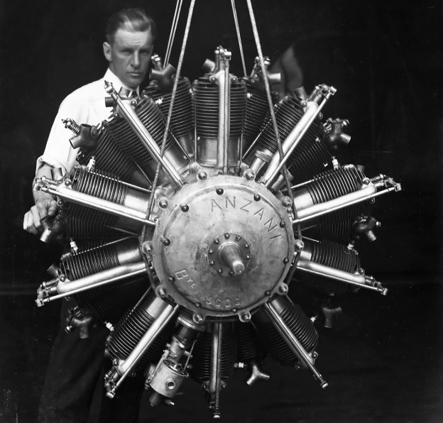
Frank Coffyn with the Azani 20-cylinder engine purchased by Robert Collier to power his Burgess Company Model L Flying Boat. Note the front carburetor under the engine and the induction pipes leading from the front crankcase chamber to the cylinders.

The Anzani company quickly went to work creating a large line of aircraft engines. In addition to the previously offered V-twin and three-cylinder fan engines, single-row three-, five-, and seven-cylinder radials were built. In the never-ending search for more power, the new single-row engines were used as a basis for two-row engines with six, ten, and 14 cylinders. In 1912, the two-row, 10-cylinder engine was used to develop a four-row, 20-cylinder radial, one of the most powerful engines of the time.

The Anzani 20-cyinder air-cooled radial was constructed in a similar fashion as other Anzani engines. The direct-drive engine consisted of four rows of five cylinders. However, the front two rows and the rear two rows were essentially paired together. The engine appeared more as a two-row radial with 10 cylinders in each row. The cylinders of a single row were separated by 72 degrees, paired rows were separated by 36 degrees, and all cylinders were separated by 18 degrees.

Anzani-20-cylinder-Frank-Coffyn-Burgess-Model-L

Coffyn stands in the Model L Flying Boat with the 20-cylinder engine mounted between the biplane’s wings. It appears the engine’s installation allowed for unrestricted access to cooling air.

The engine had an aluminum crankcase made in three parts. The central casting comprised the power section with four rows of five cylinders. The front and rear castings acted as covers and were secured to the central casting via studs. They also supported the respective ends of the crankshaft via roller bearings pressed into their castings. The rear casting also supported the accessory drives for the two magnetos. The hollow, two-throw crankshaft did not have a center support. The connecting rods for the front and rear cylinder row pairs were placed side-by-side on a common crankpin and used slipper-type bearings. The two crankshaft throws had an included angle of 162 degrees.

Under the engine, two carburetors were mounted—one toward the front and one toward the rear. Air was drawn through the carburetors and into separate chambers in the crankcase that fed the front and rear cylinder-row pairs. The air and fuel mixture was delivered from the chambers to the individual cylinders via a vertical pipe that ran along the outside of each cylinder. A single automatic (atmospheric) intake valve admitted the air and fuel mixture into the cylinder. The incoming charge was ignited by a single spark plug, and the exhaust was expelled via a short bifurcated exhaust stack. Each exhaust valve was operated via a rocker arm and push rod. The push rods were actuated via roller tappets from a cam ring. A cam ring at the front of the engine controlled the exhaust valves for the front pair of cylinder rows, and a cam ring at the rear of the engine controlled the exhaust valves for the rear pair of cylinder rows. Each cam ring had four lobes and ran at .25 crankshaft speed.

Anzani-20-cylinder-Burgess-Model-L

Right-rear view of the Model L provides a good view of the 20-cylinder engine in the pusher configuration. Note the extension shaft leading to the wooden four-blade propeller (made up of two two-blade units) that was 8 ft 4 in (2.54 m) in diameter.

Each of the cylinders was secured to the crankcase via two long lugs that passed through the crankcase to the cylinder head. The cylinders were made of cast iron with an integral cylinder head and cooling fins. The engine’s flat top pistons were made from cast iron. Each of the two magnetos attached to the rear of the engine fired half of the cylinders, with one magneto firing the left cylinders and the other firing the right cylinders.

The Anzani 20-cyinder air-cooled radial had a 4.13 in (105 mm) bore and a 5.51 in (140 mm) stroke. The engine’s total displacement was 1,480 cu in (21.25 L), and it produced 200 hp (149 kW) at 1,250 rpm. The 20-cylinder engine weighed 682 lb (309 kg).

The 20-cylinder engine was completed and tested by early 1913. For testing, the engine was secured in what resembled an aircraft’s frame complete with wheels and run stationary on the ground. One of the first (perhaps the first) engines was purchased by Robert Joseph Collier for use in a Burgess Company Model L Flying Boat that Collier was having built. Collier created the Collier Trophy that was first awarded in 1911 and continues to be awarded today “for the greatest achievement in aeronautics or astronautics in America, with respect to improving the performance, efficiency, and safety of air or space vehicles, the value of which has been thoroughly demonstrated by actual use during the preceding year.” The Burgess Company (or the Burgess Company and Curtis, Inc) was founded by William Starling Burgess and Greely S. Curtis at Marblehead, Massachusetts in 1910.

Anzani-20-cylinder-Collier-Burgess-Model-L

Robert Collier piloting the Model L over Lower New York Bay in late 1913.

The Anzani 20-cylinder engine was shipped to the United States in mid-1913 and installed in the Model L. The Model L Flying Boat was a pusher biplane that had a 41 ft 4 in (12.60 m) wingspan, was 30 ft 6 in (9.30 m) long, and had gross weight of 2,050 lb (930 kg). The aircraft’s top speed was around 75 mph (121 km/h). The Anzani engine was installed between the aircraft’s wings, and it turned a four-blade, 8 ft 4 in (2.54 m) diameter propeller via an extension shaft. The Model L made its first flight on 19 July 1913 piloted by Frank Coffyn.

Another 20-cylinder engine was part of the Anzani display at the Salon de l’Aéronautique in Paris in December 1913. Other Anzani engines displayed were the 3-, 5-, 7-, 10-, and 14-cylinder radials. The 20-cylinder engine was offered through 1915, but it seems that not many were sold. Involvement in World War I might have ended whatever limited production run the engine had. No aircraft beyond the Burgess Model L are known to have flown with the Anzani 20-cyliner. The engine in Collier’s Model L was removed during World War I and eventually given to the West Side YMCA in New York, New York around 1919 where it was used as an instructional aid.

Anzani-20-cylinder-YMCA

The 20-cylinder engine in the possession of the West Side YMCA in New York circa 1919. The engine was used as an instructional aid, but it is not known what ultimately happened to the 20-cylinder engine. Note the engine’s mounting ring which could be used in tractor or pusher installations.

Sources:
1914 Types Anzani Engines (1914)
A History of Aeronautics by E. Charles Vivian (1921)
Aerosphere 1939 by Glenn D. Angle (1939)
Les moteurs Anzani by Gérard Hartmann (22 February 2007)
– “Anzani Engines and the new 200 HP Model,” Flight (5 July 1913)
– “Aero Engines at the Paris Show, 1913” Flight (24 January 1914)
https://it.wikipedia.org/wiki/Alessandro_Anzani
https://www.massairspace.org/virtualexhibit/vex2/1F65C006-0846-475A-BC6B-417149855051.htm

Caffort-12Aa-rear

Caffort 12Aa 12-Cylinder Aircraft Engine

By William Pearce

In the late 1910s, French engineers Jean Joseph Marie Bertrand and Louis Joseph Henry Solant conceived of a modular engine concept that was known as the Bertrand-Solant design. The Bertrand-Solant engine design was based on a flat, four-cylinder rotating assembly that used a crankshaft with either two or four throws that were in the same plane, 180 degrees apart. The four-cylinder rotating assembly was unbalanced, but multiple four-cylinder rotating assemblies could be combined at angles (clocked) dependent to the number of rotating assemblies to create balanced, large engines up to 28-cylinders.

Caffort-12Aa-rear

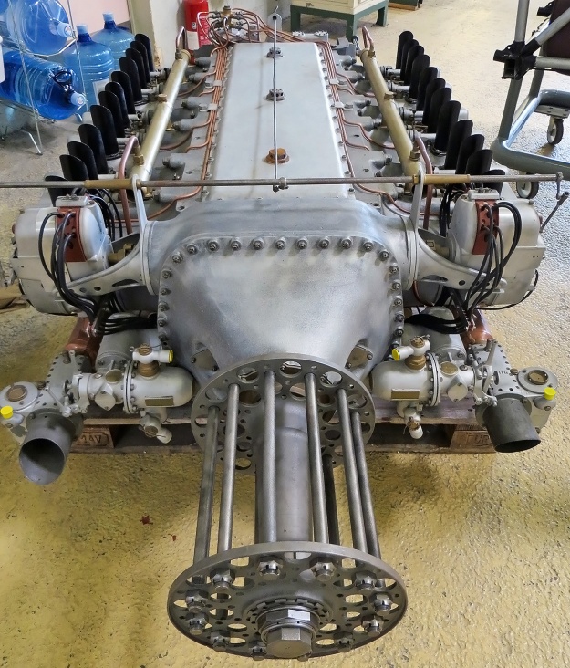
Rear view of the Caffort 12Aa engine much as it appeared at the 1926 Paris Salon de l’Aviation. The engine’s large top cover is removed to display the crankshaft and inside the crankcase. Note the pushrod tubes extending between the exhaust stacks and the crankshaft-driven water pump.

On 13 May 1921, Bertrand and Solant submitted a patent application in France to cover their engine design. While the French patent has not been found, other patents were taken out in Germany (373,157 / 412,196), the United States (1,634,866 / 1,673,484), Spain (81,435), Austria (97,016), Switzerland (103,293), and Britain (179,959).

Anciens Établissements Caffort Fréres (Caffort Brothers) in Paris produced parts for automobiles before World War I. During World War I, the company produced aircraft engines under license. In the early 1920s, Caffort built its own automobile chassis which found limited success. Powered by a two-cylinder, horizontally-opposed, air-cooled engine, the front-wheel drive machine was out of production by 1922. In 1923, the company decided to build a large aircraft engine. A few configurations were considered, but ultimately a 12-cylinder horizontally-opposed (180-degree V-12) engine of the Bertrand-Solant design was selected. This engine was known as the Caffort 12Aa, and its flat configuration would enable its installation submerged within the wing of larger aircraft. Most sources state that Caffort purchased a license for the Bertrand-Solant design, but it seems that at least Bertrand was involved with the engine’s construction.

The 12Aa had a large, one-piece, aluminum crankcase that was closed out by top and bottom covers and the propeller gear reduction. Cast integral with the crankcase were the cylinder blocks. Each block consisted of a pair of cylinders, and there were three blocks on each side of the engine. At the center of the crankcase was the three-piece crankshaft supported by four roller main bearings. Each crankshaft section had two throws and served four cylinders. The sections were united via tapered and keyed joints, and each section was clocked 120 degrees from the next. Attached to each hollow crankpin was a fork-and-blade tubular connecting rod that served one cylinder on each side of the engine. The cast pistons were made of an aluminum-silicon alloy.

Caffort-12Aa-engine-stand

The 12Aa in a rotating assembly stand. Visible are the three cylinder blocks, each with a pair of cylinders. The long intake manifold can be seen under the cylinder bank. Note the four spark plugs in each cylinder pair valve cover.

Steel cylinder liners were inserted in the cylinder blocks, and an aluminum cylinder head sealed the pair of cylinders in each block. The cylinder’s compression ratio was 5.3 to 1. Each cylinder had two intake valves in its lower side and two exhaust valves in its upper side. Four camshafts were housed in the crankcase, with one at each corner, and the camshafts were driven from the rear of the crankshaft via spur gears. The camshafts acted on enclosed pushrods that ran along the upper and lower sides of their respective cylinders to actuate the valves via rocker arms. A cover concealed the valve gear atop each cylinder pair. A water pump driven from the rear of the crankshaft supplied coolant to the lower side of each cylinder bank via separate manifolds. The water circulated through the cylinder water jackets and was collected in a manifold that ran along the upper side of the cylinder bank. Each cylinder pair had a single coolant inlet and a single coolant outlet.

A tubular intake manifold under each bank of cylinders extended the length of the engine. A carburetor was mounted to the front and rear of each manifold, giving the engine a total of four carburetors. The air and fuel charge in each cylinder was ignited by two spark plugs in the cylinder head. The spark plugs were fired by two magnetos mounted at the front of the engine and just behind the gear reduction. The magnetos were driven from the crankshaft via a transverse shaft. Two fuel pumps driven by right-angle drives from another transverse shaft were mounted below the magnetos. The exhaust gases were expelled from the cylinders via individual stacks atop the engine.

Caffort-12Aa-engine-front-Aerofossile2012

Image of the 12Aa in the Le Bourget Air & Space Museum providing a good top view of the engine, the upper crankcase cover, and the magnetos. Note the fuel pumps by the front carburetors. (Aerofossile2012 image)

The engine’s propeller shaft was coaxial to the crankshaft and turned at .53 engine speed. The propeller gear reduction was achieved by compound spur gears that ran on two layshafts—one mounted on each side of the crankshaft. A gear mounted to the crankshaft engaged teeth on the rear half of each compound spur gear. The front half of each compound spur gear engaged teeth on the propeller shaft. The engine’s configuration also enabled the removal of the compound reducing gears and the substitution of a direct drive propeller shaft. An air starter was mounted at the rear of the engine.

The Caffort 12 Aa had a 5.71 in (145 mm) bore and a 5.91 in (150 mm) stroke. The engine’s total displacement was 1,814 cu in (29.72 L). The 12Aa produced 550 hp (410 kW) at 2,000 rpm and 600 hp (447 kW) at 2,200 rpm. The engine had a length of 7 ft 3 in (2.20 m), a width of 4 ft 1 in (1.25 m), a height of 1 ft 10 in (.55 m), and a weight of 1,213 lb (550 kg).

Initially, Caffort planned to build six 12 Aa engines, but it appears that only one prototype was made. The engine was completed in the fall of 1926 and was first run in late October or early November. It was then displayed at the 1926 Paris Salon de l’Aviation (Air Show). The 12 Aa underwent testing in 1927 and recorded and output of 570 hp (425 kW) at 2,030 rpm. Either mechanical or financial issues (or both) were encountered, and development of the 12 Aa was not continued. The sole Caffort 12Aa was preserved and is held by the Le Bourget Air & Space Museum near Paris.

Caffort-12Aa-engine-close-Aerofossile2012

Note the attachment of the nose case to the 12Aa. The layshafts and spur reduction gears in the nose case could be removed and a new propeller shaft fitted to enable direct drive. (Aerofossile2012 image)

Sources:
Jane’s All the World’s Aircraft 1928 by C. G. Grey (1928)
Les Moteurs a Pistons Aeronautiques Francais Tome I by Alfred Bodemer and Robert Laugier (1987)
– “Les moteurs d’aviation exposés au 10ᵒ Salon,” L’Aéronautique Volume 9 Number 12 (January 1935)
– “The Paris Aero Show 1926,” Flight (9 December 1926)
– “Internal-Combustion Engine with Cylinders Arranged in Two Opposite Lines” US patent 1,634,866 by Jean Joseph Marie Bertrand and Louis Joseph Henry Solant (filed 20 April 1922)
– “Internal-Combustion Engine with Cylinders Arranged in Two Opposite Lines” US patent 1,673,484 by Jean Joseph Marie Bertrand and Louis Joseph Henry Solant (filed 30 November 1926)

Fairchild-Caminez-447-C

Fairchild Caminez 447 Radial Cam Engine

By William Pearce

Harold Caminez was born in Brooklyn, New York on 1 March 1898. He received a degree in Mechanical Engineering from Cornell University in 1919 and was awarded a master’s degree in 1920. After graduating from Cornell, Caminez worked as a civilian engineer for the United States Army Air Corps (AAC) Engineering Division at McCook Field in Dayton, Ohio.

Caminez-Radial-Cam-Engine-prototype

The Radial Cam Engine prototype was built-up quickly to test the cam-drive system, but the engine’s basic configuration carried on throughout the later Fairchild Caminez 447 series. Note the rocker arm setup, the large side-engine mount, and the long intake runners. (Aircraft Engine Historical Society image)

While at McCook Field, Caminez designed a new type of radial aircraft engine in which the crankshaft was replaced by a camshaft with two large lobes. The engine was called the Radial Cam Engine. The cam lobes contacted the pistons via a large roller bearing installed in the skirt of each piston. With the two lobes, each piston would go through four strokes (one of which was the power stroke) for every revolution of the camshaft, which would directly drive the propeller. Compared to a conventional radial, Caminez’s design would produce the same number of power strokes at half the RPM; this meant that the engine did not need a propeller gear reduction. In addition, the Radial Cam Engine design eliminated some 40 percent of the parts found in a conventional engine, making it much lighter than a conventional engine and possibly cheaper to manufacture. The Radial Cam Engine was seen as a potential replacement for the outdated yet abundant Curtiss OX-5 V-8 that was used at the time in many light aircraft. Caminez was able to gather enough interest in the Radial Cam Engine that the AAC supported construction of a prototype starting in 1923.

The Radial Cam Engine prototype had four cylinders placed at 90-degree intervals around the engine case. The barrel-type aluminum engine case was closed out by front and rear covers. The drive camshaft was supported by two main bearings—the rear main bearing was in the rear cover, and the front main bearing was in the engine case. The lobe assembly was machined separately from the camshaft and consisted of two lobes that were in the same plain. Despite a very similar appearance, the lobe profiles were different, with one lobe optimized for the compression and power strokes and the other lobe optimized for the exhaust and intake strokes. In addition, the leading side of the lobe was profiled to maximize thrust as it pushed the piston toward the combustion chamber, and the trailing side was profiled to keep the piston in constant contact with the lobe as the piston moved toward the camshaft. A splined hole at the center of the lobe assembly enabled its installation on the camshaft. Oil flowed through the hollow camshaft and into passageways within the lobe assembly. Two holes on the surface of each side of the lobe assembly sprayed oil within the engine and lubricated the piston roller bearings. The propeller mount engaged splines on the front of the camshaft, and the engine rotated clockwise when viewed from the rear.

Fairchild-Caminez-447-B-drawing

Drawings of the Fairchild Caminez 447-B, but all of the 447 engines had similar layouts. Note the general interaction of the camshaft, pistons with their roller bearings, and the link holders connecting the pistons. Starting with the 447-C, the link holders joined at a common point.

The large roller bearing in the skirt of each piston was secured by a piston pin. Via their bearings, the pistons drove the camshaft on the power stroke and were driven by the camshaft on the compression and exhaust strokes. For the intake stroke, the piston was pulled back toward the camshaft by to pairs of link holders that joined the piston to the pistons in adjacent cylinders. The link holders were mounted below and on each side of the roller bearing’s axis. Each link holder pair extended in front and behind the camshaft lobe to connect to an adjacent piston.

The air-cooled steel cylinders were attached to the engine case via a series of studs. Slots were cut into the bottom of the cylinder barrel to provide clearance for the link holders. Each cylinder had one intake valve and one exhaust valve, both of which were closed by volute springs. A sleeve containing two separate small lobes was keyed to the front side of the camshaft. These lobes drove roller followers that acted on pushrods to actuate the intake and exhaust valves. The pushrods extended vertically in front of the cylinder to exposed rocker arms mounted atop the cylinders. The intake port was at the rear of the cylinder, and the exhaust port was on the left side of the cylinder. The carburetor was mounted to an intake manifold at the rear of the engine, and the air/fuel mixture was delivered to each cylinder via separate intake runners. Each cylinder’s two spark plugs were fired by a battery-powered distributor driven from the rear of the engine.

The Radial Cam Engine prototype had a 5.625 in (143 mm) bore and a 4.50 in (114 mm) stroke. The engine displaced 447 cu in (7.33 L) and had a compression ratio of 5.59 to 1. Cylinder firing order was 1, 2, 3, and 4. The prototype engine’s forecasted performance was a maximum output of 220 hp (164 kW) at 1,500 rpm and 180 hp (134 kW) at 1,200 rpm. The engine had a 41 in (1.04 m) diameter and weighed 417 lb (189 kg).

Fairchild-Caminez-447-pistons

Left: Cam lobes, pistons, and link holders of the Radial Cam Engine prototype. Right: Cam lobes, pistons, and link holders of the 447-C. The piston design changed incrementally throughout the series, but the 447-C was the first to have the link holders join at a common point.

Some compromises existed with the Radial Cam Engine prototype. It was seen as a proof-of-concept engine, and weight was not a concern. The cylinders used were not designed specifically for the engine, and it was anticipated that they would be operating beyond their capabilities at full power. If the engine’s crankless design proved to be sound, then additional resources would be allocated to optimize engine components.

The prototype engine was completed in May 1924 and was installed on a dynamometer later that month. Motoring tests were begun with the engine being powered by the dynamometer. The tests revealed some weaknesses, and repairs were made. The Radial Cam Engine ran for the first time on 18 July 1924. During preliminary testing, many problems were encountered, most of which were tied to the engine’s excessive vibrations and overheating. The overheating was in part due to the inadequate cylinder design, but the other issues required modification of the engine. Through the first test sessions, the engine averaged about 105 hp (78 kW) at 880 rpm.

In August 1924, the Radial Cam Engine was rebuilt with a new engine case, new pistons, and many other improved components. The engine test cell was modified to incorporate a fan blowing air over the engine at 70 mph (113 km/h) to aid cooling. A second round of testing was run from September 1924 through February 1925. Again, numerous issues were encountered with nearly every part of the engine. However, the tests concluded that the engine’s camshaft drive operated well enough to warrant further development.

Fairchild-Caminez-447-A

Front and rear views of the 447-A. Note the revised valve train and induction system compared to the prototype engine. Tie rods can be seen between the rocker bracket and the engine case. (Aircraft Engine Historical Society images)

Caminez had left the Engine Design Department and took a job as the Vice President and Chief Engineer of the Fairchild Caminez Engine Corporation, which was founded on 2 February 1925. Sherman Fairchild was an entrepreneur who founded Fairchild Aerial Camera Corporation in 1920 and Fairchild Aerial Surveys in 1921. Through the aerial camera business, Fairchild learned of Caminez and thought that his engine was exactly what civil aviation needed for the next generation of private and trainer aircraft. Fairchild was able to convince Caminez to partner together for the new venture, and the AAC was happy to have private industry take over development of the Radial Cam Engine. Fairchild also founded the Fairchild Airplane and Manufacturing Company later in 1925 to initially produce aircraft for aerial mapping.

With new support, Caminez redesigned the Radial Cam Engine, which became the Fairchild Caminez Model 447-A. While the bore, stroke, and operating principle of the engine remained unchanged, many improvements were incorporated into the new 447-A engine. A new two-piece engine case that was split vertically through the cylinders’ center line was developed. A flange around the rear of the engine case was used for engine mounting. The camshaft was now supported by three bearings: one on each side of the lobes and the third at the front of the engine. The valve train was altered to provide more room for the pushrods. A new spring provided tension for the pushrod against the roller follower. The placement of the rockers was altered to provide a better angle for valve actuation. A new support extended between the rocker mount atop the cylinder and the engine case. The carburetor was now mounted under the engine and delivered the air/fuel mixture to an internal manifold within the rear of the engine case. Individual runners extended along the backside of the cylinders to distribute the air/fuel charge into the cylinders. The induction system was designed so that each of the carburetor’s two barrels delivered air to cylinders located on opposite sides of the engine. New pistons were developed to provide better movement of the roller bearings and link holders. The cylinders were modified with slightly increased cooling fin area, and two magnetos driven from the rear of the engine fired the spark plugs.

Avro-504-477-A-R-Loftis

The modified 447-A engine with coil valve springs installed in an Avro 504 biplane. Harold Caminez is at left; pilot Richard Depew is at center; and Sherman Fairchild is at right. (Richard E. Loftis image via the Aircraft Engine Historical Society)

The 447-A was forecasted to produce 150 hp (12 kW) at 1,200 rpm, a substantial decrease in output compared to the original Radial Cam Engine estimates but an increase from what the prototype engine had actually achieved. The engine weighed 407 lb (185 kg). On 1 May 1925, the 447-A engine was delivered to the AAC Engineering Division for testing. The engine was motored from 9 May through 4 June, and many parts were found damaged and worn at the end of the test. The repaired engine was run under its own power between 17 June and 25 July in an attempt to pass a 50-hour type test. On top of many minor issues, vibrations and overheating were still a problem. There were also signs that the piston roller bearings were not staying in contact with the cam lobes and were causing some hammering to the lobes.

The engine was again repaired with improved parts, and another 50-hour test was attempted between 4 August and 15 September 1925. After 16 hours, the tests were halted and the engine was shipped back to Fairchild Caminez for repairs. Many valve train components had failed; the link holders were coming into contact with the cylinder cutouts, and the engine’s vibrations resulted in two broken propellers. The US Navy had similar results with a separate 447-A test engine that had been sent to them for testing.

Modifications were made to the 447-A, including switching out the volute valve springs in favor of coil springs. The modified 447-A was installed in an Avro 504 biplane for testing, and the combination made its first flight on 12 April 1926, flown by Richard Depew. This marked the first occasion that an aircraft was powered by a crankless engine.

Fairchild-Caminez-447-B

The 447-B was refined from the 447-A. The valve train had again been updated; the cylinders had an aluminum head, and the exhaust port was moved to the back of the cylinder. Note the large brackets for the rocker arms.

The engine was reworked, resulting in the Fairchild Caminez 447-B. The engine case was modified and the valve train was revised. The rocker mounts were strengthened, and the springs adding tension between the pushrods and the roller followers were eliminated. The cylinders were redesigned with a cast aluminum cylinder head screwed and shrunk onto a steel barrel. An inner cylinder piston guide extended below the cylinder barrel. As its name implies, it helped guide the piston when it was at bottom dead center, but it also supported the piston during removal of the cylinder for servicing. Both the intake and exhaust ports were on the back side of the cylinder. The performance specifications of the 447-B were again reduced, with a maximum output of 135 hp (101 kW) at 1,050 rpm and 126 hp (94 kW) at 900 rpm. The engine had a compression ratio of 5.2 to 1 and weighed 360 lb (163 kg).

The Avro 504 was reengined with the 447-B, and other aircraft that were tested with engine include a Waco 10 biplane, a Fairchild FC-2W high-wing monoplane, and a Spartan C3 biplane. However, the 447-B engines were eventually removed due to vibration issues and overheating. It was found that the slow-turning engine necessitated a rather large propeller. A 10 ft (3.05 m) two-blade or an 8 ft 6 in (2.59 m) four-blade propeller was recommended, but the large diameter necessitated three-point takeoffs and landings for some aircraft. The propeller’s large hub and low rpm did not provide sufficient cooling airflow to the engine cylinders below 60 mph (97 km/h). The engine also had a tendency to fray and break the tips of the wooden propellers.

Waco-10-447-B

A Waco 10 with a 447-B engine. This aircraft was eventually fitted with a 447-C and was flown by Myron Gould “Dan” Beard for over 6,300 miles in the Ford Reliability Tour of 1928.

Again, the engine was revised, creating the 447-C. The engine case was updated. New pistons were designed with lower skirts that were notched to clear the cam lobe. The link holders were updated so that both rods on one side of the piston attached to the same point, just below the piston pin. Quality control was improved in an effort to prevent the occasionally poor machining that had plagued earlier engines. The Fairchild Caminez 447-C produced 145 hp (108 kW) at 1,100 rpm, 135 hp (101 kW) at 1,000 rpm, and 125 hp (93 kW) at 900 rpm. The engine had a 5.0 to 1 compression ratio and weighed 350 lb (159 kg). The 447-C had a length of 34 in (.86 m), a width and height of 36 in (.91 m), and a diameter of 41 in (1.04 m). Fuel consumption was .55 lb/hp/hr (334 g/kW/h) at full throttle and .48 lb/hp/hr (292 g/kW/hr) at cruise power.

The 447-C was installed in various aircraft for testing. including a Waco 10 biplane, a Travel Air 8000 (4000-CAM) biplane, a Kreider-Reisner Challenger C-2 biplane, and a Boeing Model 81 biplane trainer. Fairchild Caminez made efforts to market the engine commercially, and the engine underwent the Department of Commerce’s new process for an Approved Type Certificate (ATC). A 447-C engine was submitted for type certification testing in the spring of 1928. Engine output at the start and end of the 50-hour test were 119 hp (89 kW) at 960 rpm and 121 hp (90 kW) at 980 rpm respectively. As a result of the tests, the 447-C was officially rated at 120 hp (89 kW) at 960 rpm. The 447-C was the first engine to successfully complete the type certificate process, being awarded engine ATC No. 1 on 1 June 1928.

Fairchild-Caminez-447-C

Once the 447-B fell short, production hopes fell on the 447-C. While the engine case was slightly updated, the primary changes to the 447-C were internal, with new pistons and link holders. (Aircraft Engine Historical Society image)

On 30 June 1928, a 447-C-powered Waco 10 and a Travel Air 8000 were two of 26 entries to compete in the Ford Reliability Tour of 1928. A 447-C-powed Kreider-Reisner Challenger C-2 also attempted to enter, but its engine and propeller were damaged on the delivery flight. The tour concluded on 28 July after covering 6,304 miles (10,145 km). The two 447-C-powered aircraft were able to complete the contest, but it took a traveling team of mechanics to keep the engines in good operating order. Approximately eleven propellers were needed to get the two aircraft to the finish line.

A two-row, eight-cylinder engine was built, but few details and no drawings or photos of the engine are known to exist. The second row of cylinders was directly behind the first, and the lobes for the two rows were staggered at 45 degrees on the camshaft. Most likely, the eight-cylinder engine shared as many common components as possible with the four-cylinder engine, but the bore and stroke are not known. Assuming the same 5.625 in (143 mm) bore and 4.50 in (114 mm) stroke were used, the eight-cylinder engine would have displaced 895 cu in (14.66 L). While the eight-cylinder engine ran smoother, it ran too hot, with the second row of cylinders overheating severely.

One final four-cylinder engine was designed, although it is not exactly clear when. The 447-D was the most advanced of the Caminez engines. The engine case was once again updated, this time to accommodate major changes to the cylinders and valve train. The cylinders had increased cooling fin area, and the valves were relocated. The exhaust valve and its pushrod were moved to the very front of the cylinder, and the intake valve and its pushrod were at the rear of the cylinder. An intake cam lobe was added to the rear of the camshaft, and all pushrods were enclosed in tubes. The rockers were enclosed and supported by the cylinder casting rather than by brackets bolted to the cylinder head, as used on earlier engines. The 447-D may have had an anticipated output of 145 hp (108 kW) at 1,000 rpm, but it is not known if the engine was tested or flown. The 447-D was approximately 29 in (.74 m) long and 39.5 in (1.00 m) in diameter.

Fairchild-Caminez-447-C-NASM

A Fairchild Caminez 447-C cutaway engine held at the Smithsonian National Air and Space Museum. Note the “Caminez Engine” and Fairchild logo stamped into the propeller hub. (NASM image)

For aircraft installations, the 447 engines needed to run around 600 rpm in order to keep the vibrations somewhat under control. Even so, engine vibrations continued to abuse the wooden propellers by breaking the tips or charring the holes around the attachment bolts. The aircraft also endured the abusive vibrations that relentlessly caused wires to snap or parts to loosen and fall off. By October 1928, only around 40 engines had been produced, with 10 being purchased by Japan and the rest used for testing. The Fairchild Caminez Engine Corporation conducted an independent assessment of the engine program, which concluded that some $2 million would be needed to fix the engine and bring it to production status. The company had already spent $800,000 and decided that it had spent enough. The cam-drive 447 engine program was cancelled in late 1928, and Caminez resigned from the company. The Fairchild Caminez Engine Corporation became the Fairchild Engine Corporation in May 1929, and work was soon initiated on what would become the inverted, air-cooled, six-cylinder, inline 6-370 engine.

Harold Caminez went on to do detailed design work on the Allison V-1710 V-12 engine in the early and mid-1930s, invented the Heli-Coil in the mid-1930s, and helped design the Lycoming XH-2470 H-24 and XR-7755 IR-36 engines in the late 1930s and early 1940s. On 28 July 1943, he and 19 others were killed in the crash of American Airlines Flight 63. Caminez was on a business trip for Lycoming when the Douglas DC-3 went down due to weather west of Trammel, Kentucky.

At least six Caminez 447 engines survive. Three 447-C engines are held in storage by the Smithsonian National Air and Space Museum: one is complete; one is a cutaway; and one is a motorized cutaway. The motorized cutaway was donated by the Fairchild Aviation Corporation and was most likely a display engine. Another 447-C is held by the Canada Science and Technology Museum in Ottawa, Canada. The Smithsonian also has a 447-D in storage. Another 447-D engine is on display at the Alfred & Lois Kelch Aviation Museum in Brodhead, Wisconsin.

Fairchild-Caminez-447-D-R-Loftis

The Fairchild Caminez 447-D engine was a complete redesign with a new engine case and new cylinders. The exhaust valve is on the front of the cylinder, while the intake valve is at the rear, and the rocker arms are completely enclosed. The design appears much more refined compared to the earlier 447 engines. (Richard E. Loftis image via the Aircraft Engine Historical Society)

Sources:
– “The Fairchild-Caminez Engine” by Paul Christiansen, Torque Meter Volume 7, Number 4 (Fall 2008)
The Caminez Engine by the Fairchild Caminez Engine Corporation (circa 1928)
Dyke’s Aircraft Engine Instructor by A. L. Dyke (1929)
– “Cam Engine” US patent 1,594,045 by Harold Caminez (filed 31 March 1924)
– “Piston” US patent 1,687,265 by Harold Caminez (filed 2 April 1927)
– “Internal-Combustion Engine” US patent 1,714,847 by Harold Caminez (filed 2 April 1924)
Fairchild Aircraft 1926–1987 by Kent A. Mitchell (1997)
The Ford Air Tours 1925 – 1931 by Lesley Forden (1972/2003)
https://www.enginehistory.org/Biography/CaminezHarold/CaminezHarold.shtml
http://enginehistory.org/Piston/Fairchild/Fairchild.shtml
https://dmairfield.org/events/fordreliabilitytour/index.htm
https://airandspace.si.edu/collection-objects/fairchild-caminez-447-c-radial-4-engine-cutaway/nasm_A19731576000
https://airandspace.si.edu/collection-objects/fairchild-caminez-447-c-radial-4-engine/nasm_A19710915000
https://airandspace.si.edu/collection-objects/fairchild-caminez-447-c-radial-4-engine/nasm_A19320038000
https://www.enginehistory.org/id_unknown.shtml

SNCAC-NC-3021-front-no-cowling

SNCAC NC 3021 Belphégor High-Altitude Research Aircraft

By William Pearce

In the early 1930s, Avions Farman (Farman) built the F.1000-series of aircraft to break altitude records. On 5 August 1935, the F.1001 reportedly achieved stable flight at around 10,400 m (34,120 ft). However, one of the small windows in the aircraft’s pressure vessel soon failed. The sudden decompression incapacitated the pilot, Marcel Cognot, and the aircraft crashed.

SNCAC-NC-160-model

Model of the pre-war NC 160 dive bomber displays the basic layout that would be scaled-up for the NC 3020.

In late 1936, France began a program of nationalizing its arms industry, which many aviation manufacturers fell under. In early, 1937 Farman was combined with Aéroplanes Hanriot to create the state-run Société Nationale des Constructions Aéronautiques du Center (SNCAC or Aérocentre, the National Company of Aeronautical Constructions of the Center).

SNCAC initiated development of some advanced aircraft and designed other aircraft to serve as technological testbeds. One of these aircraft was the NC 130 (NC standing for Nationale Center), a twin-engine monoplane built around a cabin pressure vessel. The NC 130 was designed by Marcel Roca, the former head of the Farman design office, and it had an anticipated service ceiling of 34,777 ft (10,600 m). The NC 130 made its first flight in 1939 but was destroyed in the early part of World War II. Roca and his team also designed the NC 160, a monoplane dive bomber with contra-rotating propellers. The NC 160 did not progress beyond the design stage.

After the German invasion of France on 10 May 1940, SNCAC personnel and offices were relocated south from Boulogne-Billancourt, near Paris, and untimely to Cannes on the Mediterranean Sea. SNCAC, along with SNCASE (Société nationale des constructions aéronautiques du Sud-Est, National Company of Aeronautical Constructions of the South East), SNCAO (Société nationale des constructions aéronautiques de l’ouest, National Company of Aeronautical Constructions of the West), and CAMS (Chantiers Aéro-Maritimes de la Seine, Aero-Maritimes construction sites of the Seine) were combined with and operated under SNCASO (Société nationale des constructions aéronautiques du sud-ouest, National Company of Aeronautical Constructions of the South-West). At the time, southern (Vichy) France operated as an independent and unoccupied ally of Germany, but the state’s “independence” from Germany was certainly not absolute. The German overseers allowed the continued development of commercial and civil aircraft in Southern France.

SNCAC-NC-3021-right-side

The NC 3021 before the dorsal fairing was added forward of the vertical stabilizer. Note the glazing on the lower fuselage. Between the panels was the lower pressure cabin bulge with observation ports.

Roca and the SNCAC team were put in charge of the special aircraft division, which would use the SO 3000-series to designate their designs, SO standing for Sud-Ouest (South West). The SO 3020 was an experimental high-altitude research aircraft designed to observe stratospheric and meteorological conditions, and the basic layout of the aircraft was based on a scaled-up version of the pre-war NC 160 dive bomber design.

The fuselage of the large, taildragger aircraft consisted of three sections. The forward fuselage housed two 1,400 hp (1,030 kW) Hispano-Suiza 12Z engines placed side-by-side and mounted on a tubular frame. Each engine powered half of a six-blade, coaxial, contra-rotating propeller via a SNCAC-designed combining gearbox designated NC T1.

The central fuselage was built around a welded pressure vessel that was 17 ft 1 in (5.20 m) long and 5 ft 7 in (1.70 m) in diameter. A bulge atop the pressure vessel was the cockpit that protruded above the fuselage. A bulge in the lower part of the pressure vessel contained two viewing stations for observations and photography of the stratosphere. The lower bulge was contained within the aircraft’s fuselage, but the fuselage was glazed around the bulge. The cabin pressure vessel accommodated five people: the pilot, a radio operator/navigator, a mechanic, and two scientists/observers. Pressurization of the cabin was achieved by two SNCAC-designed NC 41 positive displacement compressors that were driven directly from the engines. The cabin was accessed via a door in the rear fuselage that led to a hatch at the back of the pressure vessel.

SNCAC-NC-3021-right-rear

Rear view of the NC 3021 illustrates the upper pressure cabin bulge for the cockpit. Note the observation ports on the side of the fuselage.

While the forward and center fuselage sections were all-metal monocoque designs, the rear fuselage had a spruce frame that was covered in plywood. The vertical and horizontal stabilizers were also made of wood, but the rudder and elevators had metal frames that were covered with fabric.

The SO 3020’s three-spar wing was of mixed construction, and the main spar attached to a bulkhead that was mounted to the pressure vessel in the central fuselage. The structure of the wing was made mostly of metal, but spruce was used for the front and rear spars of the outer wing sections. The wing was covered with metal. The ailerons had metal frames and were covered in fabric. When retracted, the landing gear was fully enclosed with the main gear in the wing and the tailwheel in the fuselage. The main gear had a wide track of 18 ft 9 in (5.71 m). Tanks within the wings held the aircraft’s 1,836 US gal (6,950 L / 1,529 Imp gal) of fuel.

The SO 3020 had a wingspan of 73 ft 3 in (22.32 m), a length of 65 ft 3 in (17.90 m), and a height of 19 ft 2 in (5.83 m). It was anticipated that the aircraft would cruise at 311 mph (500 km/h) at 33,793 ft (10,300 m) and have a ceiling of 45,932 ft (14,000 m). The SO 3020 had an empty weight of 13,382 lb (6,070 kg) and a gross weight of 26,015 lb (11,800 kg). This would allow the aircraft to carry 11,023 lb (5,000 kg) of fuel, 1,014 lb (460 kg) of freight, and five crew members. Range was 4,169 miles (6,710 km) with an endurance of seven hours.

SNCAC-NC-3021-front-no-cowling

The maintenance crew underneath the uncowled NC 3021 provides reference to just how large the aircraft was. The duct supplying air to the supercharger can be seen along the side of the engine. Note the open access door in the rear fuselage.

Work on the SO 3020 was allowed to move forward in mid-1941, but progress was slow due to the war situation. A full-size wooden mockup was built toward the end of 1942. When Germany invaded Vichy France in early November 1942, progress on the SO 3020 slowed even further. In March 1943, the letter designation ‘B’ was assigned to SNCASO aircraft, and the SO 3020 was given the name “Belphégor,” for the demon who seduces people by suggesting to them ingenious inventions that will make them rich.

Construction of the SO 3020 continued throughout the war. The aircraft, its design team, and other SNCASO operations were moved west to Le Flayosquet in early 1944. This move was a result of a British air raid on Cannes in November 1943 and was finally completed in May 1944. However, after the Allied landings and subsequent liberation of France, everything was moved back to Cannes between November 1944 and January 1945. With the liberation of France, the nationalized aircraft manufacturers were restored, and SNCAC broke off from SNCASO. The SO 3020 and everything else associated with SNCAC was moved back to Boulogne-Billancourt.

By early 1946, the SO 3020 was complete with the exception of its engines. The war had delayed work on the Hispano-Suiza 12Z, and it would be some time before the engines would be available. As a result, the decision was made to switch to a single 2,950 hp (2,170 kW) Daimler-Benz DB 610 engine. The DB 610 consisted of two coupled DB 605 engines and was similar to what was planned with the two 12Z engines and the NC T1 gearbox. DB 605 engines were available to France and SNCAC in the immediate post-war era. With this new configuration, the aircraft was redesignated NC 3021. At the time, a number of experiments were planned for the aircraft to study cosmic rays and their interaction with the atmosphere.

SNCAC-NC-3021-front

Front view of the NC 3021 displays the DB 610’s side and lower exhaust stacks. Note the duct under the engine to supply air for cabin pressurization. The engine and propeller were most likely repurposed from stock intended for a German Heinkel He 177 bomber.

In March 1946, the NC 3021 was transferred from Boulogne-Billancourt to the Toussus-le-Noble airfield for final assembly. With the DB 610 engine, the contra-rotating propellers were discarded, and a single, four-blade propeller was used. This VDM propeller was 14 ft 9 in (4.5 m) in diameter and was most likely the same as that used on the German Heinkel He 177 bomber. The DB 610 engine was mounted on a tubular frame at the front of the aircraft, and an annular radiator was installed around the propeller’s extension shaft. Ducts on each side of the cowling delivered air to the transversely-mounted superchargers at the rear of the engine. Air for the cabin and its pressurization was brought in from a duct under the spinner. This sealed duct passed around the lower exhaust stacks which helped heat the air.

The NC 3021 had a wingspan of 73 ft 3 in (22.32 m), a length of 65 ft 3 in (17.90 m), and a height of 19 ft 2 in (5.83 m). The aircraft’s estimated performance was a maximum speed of 348 mph (560 km/h) at 19,685 ft (6,000 m) and a cruising speed of 280 mph (450 km/h) at 39,370 ft (12,000 m). The aircraft had a landing speed of 87 mph (140 km/h), an initial rate of climb of 1,968 fpm (10 m/s), and a ceiling of 41,995 ft (12,800 m). Compared to the SO 3020, the NC 3021’s empty weight had increased 3,880 lb (1,760 kg) to 17,262 lb (7,830 kg), and its gross weight had decreased 3,073 lb (1,394 kg) to 22,941 lb (10,406 kg).

SNCAC-NC-3021-inflight-top

Although of poor quality, this image of the NC 3021 in flight shows the dorsal fairing that was added to the tail to aid directional stability.

The NC 3021 was completed at the end of May and registered as F-WBBL. Taxi tests were initiated at the beginning of June, and the aircraft made its first flight on 6 June 1946 with Joanny Burtin as the pilot. The aircraft suffered from directional instability, and a dorsal fairing was soon added in front of the tail to increase its lateral surface area. Testing was brought to a halt later that summer when the right main gear collapsed. The landing gear manufacturer was slow to provide a new main gear leg, and SNCAC resumed flight tests as best as it could with a temporarily repaired main gear fixed in the down position.

The landing gear was eventually repaired, but the DB 610 engine proved to be difficult to service and maintain. To make matters worse, SNCAC was having financial issues and did not have the funds to spend on an experimental project that offered little in return. When SNCAC delivered the NC 3021 to the Centre d’essais en vol (CEV, Flight Test Center) at Brétigny-sur-Orge on 12 October 1948, the aircraft had only made 45 flights for a total of 40 hours of flight time.

The CEV worked to maintain and test the NC 3021. By April 1949, the CEV had put in 1,500 hours of work on the NC 3021 but had only flown the aircraft for 2 hours and 45 minutes. The CEV did not want to continue to operate the aircraft, and SNCAC declared bankruptcy in July 1949. There were no other parties interested in funding the expensive and difficult to maintain experimental aircraft, and the NC 3021 was most likely scrapped in late 1950.

SNCAC-NC-3021-inflight-right

Large, complex, and expensive, the NC 3021 was never used to collect scientific data on the stratosphere. It is doubtful that the aircraft was ever tested to its estimated ceiling.

Sources:
– “NC-3021 Belphégor: le monstre de la haute altitude” by Philippe Ricco, Avions #207 (September/October 2015)
– “NC-3021 Belphégor: le monstre de la haute altitude” by Philippe Ricco, Avions #208 (November/December 2015)
Les Avions Farman by Jean Liron (1984)
Jane’s All the World’s Aircraft 1949-50 by Leonard Bridgman (1949)
https://aviation-safety.net/wikibase/194708

Daimler-Benz-DB-606-engine-front

Daimler-Benz DB 606, DB 610, and DB 613 Doppelmotoren

By William Pearce

In 1936, Siegfried and Walter Günter began design work on the Heinkel He 119, an experimental, unarmed, high-speed light bomber and reconnaissance aircraft. The engine for the He 119 was buried in the fuselage, and the Günter brothers quickly realized that no engine available was capable of providing the desired power in excess of 2,300 hp (1,691 kW). Heinkel requested proposals from Germany’s leading aircraft engine manufacturers. Daimler-Benz responded with a plan to construct a doppelmotor (double engine) by coupling two DB 601 V-12 engines to create the 24-cylinder DB 606. Combining two engines as a single unit was seen as a quick way to double engine power without spending years to develop a new powerplant.

Daimler-Benz-DB-606-engine-front

The Daimler-Benz doppelmotoren (double engines) were quite literally formed by combining two separate engines. The DB 606 was made from two DB 601 engines. The levers attached to the combining gear reduction housing controlled the coupling and decoupling of the separate engine sections.

Development of the DB 601 was started in the mid-1930s and based on the DB 600. The main differences between the engines were that the DB 600 used a carburetor and geared supercharger, whereas the DB 601 used fuel injection and a variable speed supercharger. The DB 601 was an inverted, liquid-cooled engine with two banks of six cylinders. Its single-piece Silumin-Gamma (aluminum alloy) crankcase was closed out by a cover affixed to its top side. The six-throw crankshaft was supported by seven main bearings, and each main bearing was secured by four bolts and one transverse bolt that passed through the crankcase. The crankshaft turned counterclockwise. Fork-and-blade connecting rods were used, with the forked rods serving cylinders on the right side of the engine (when viewed from the rear). The connecting rods ran on roller bearings, but the blade rod had an additional plain bearing between it and the roller bearing.

The two cylinder blocks were made from Silumin (aluminum-silicon alloy) and attached to the bottom of the crankcase at a 60 degree angle. Each cylinder block consisted of six cylinders with integral cylinder heads. The dry cylinder liners (barrels) were made of chrome steel and were screwed and shrunk into the upper cylinder block. Threaded liner skirts protruded into the crankcase toward the crankshaft. A locking ring screwed onto each liner skirt and drew and secured the entire cylinder block to the crankcase. The locking ring had “teeth” around its outer edge and was tightened by a special pinion tool that was held secure in the crankcase and rotated the ring.

Each cylinder had two spark plugs mounted on its outer side and a fuel injector mounted on its inner side. The Bosch fuel injection pumps were mounted in the Vee between the cylinder banks. Two intake valves on the inner side of the cylinder brought in air. The combustion gasses were expelled through two sodium-cooled exhaust valves on the outer side of the cylinder. All four valves per cylinder were actuated via rockers by a single overhead (technically underhead) camshaft, which was driven by a vertical shaft at the rear of the engine.

The DB 601’s propeller shaft was driven clockwise via spur gears through a gear reduction housing mounted to the front of the engine. The gear reduction was made so that a gun or cannon could be mounted behind the engine and fire through the Vee between the cylinder banks and out the propeller’s hub. Mounted to the rear of the engine was an accessory section that provided the drives for the magnetos, generator, starter, fuel and oil pumps, and the transversely mounted supercharger.

Daimler-Benz-DB-606-engine-bottom-eng

Bottom view of a DB 606 illustrates the separate engine sections. Note the rear engine mount which joined the two engine sections. The fuel injection pump for each engine section can be seen in the Vee between the cylinder banks.

The supercharger was mounted on the left side of the engine and driven from the crankshaft via a variable speed fluid coupling. In simple terms, two oil pumps supplied oil that flowed through the supercharger coupling. One pump continuously supplied the amount of oil needed for the supercharger to operate at its lowest (sea level) speed. The second pump was barometrically controlled and gradually supplied more oil as the aircraft’s altitude increased. At the engine’s critical altitude, the second pump was supplying the maximum amount of oil, and the supercharger was at its maximum speed. There was always some degree of slip in the coupling, but it was minimal (a few percent) at full speed. The variable speed of the supercharger created a gradual power curve rather than the saw-tooth power delivery of two- or three-speed superchargers. Air from the supercharger flowed through an intake manifold that looped in the Vee between the cylinder banks.

To form the DB 606, two DB 601 engines were mounted side-by-side at an included angle of 44 degrees and joined by a common propeller gear reduction. In this configuration, the engine banks formed an inverted W, and the inner cylinder banks were only eight degrees from vertical. The right and left engine sections were respectively referred to as the “W-Motor” (or DB 601 W) and the “X-Motor” (or DB 601 X). The exhaust ports for both inner cylinder banks were positioned in the narrow space between the two engine sections. DB 606 differed from the DB 601 by using the new propeller gear reduction and a modified accessory drive. The two engine sections drove a single propeller, and no gun or cannon could be fitted to fire through the propeller hub. Bolted between the two engine sections and near their rear was a mount for suspending the back of the DB 606 to the aircraft. The left and right engine sections remained separate with the exception of the gear reduction and the rear mount.

The new gear reduction housing combined the output from the two engine sections and fed it into a single propeller shaft, which typically had an extension that was approximately 44 in (1.11 m) long. The combining gear allowed the manual decoupling and recoupling of an engine section. Recoupling could only be accomplished when the engine sections were operating at the same RPM. In addition, an engine section would be automatically decoupled if its speed dropped suddenly compared to the other engine section. The coupling of each engine was accomplished by dogs (often referred to as claws in German literature) on a flange splined to the crankshaft that engaged dogs on a coupler that drove a spur gear in the reduction housing. To disengage an engine section, a lever for that engine section on the gear reduction housing had to be pulled forward. This would pull the coupler toward the propeller and disengage it from the crankshaft. The coupler would still be connected to the gears in the reduction housing. The levers on the engine were linked to levers in the cockpit, and the individual engine sections were started one at a time.

Different combining gear reductions enabled the propeller of the DB 606 to turn either clockwise or counterclockwise without changing the counterclockwise rotation of the engines’ crankshafts. The propeller of the DB 606 A turned clockwise. A 33-tooth gear on each of the two crankshafts meshed with an 80-tooth gear on the propeller shaft to create a .4125 reduction. The combining gear on the DB 606 B incorporated idler gears in the lower housing that enabled the propeller to turn counterclockwise. The idler gears increased the engine’s weight by approximately 88 lb (40 kg). For the DB 606 B, a 31-tooth gear on each of the two crankshafts meshed with 39-tooth idler gears, which engaged the 75-tooth gear on the propeller shaft to create a .4133 reduction. With two fewer gears, the combining gear reduction housing on the DB 606 A was initially smaller with angled corners when compared to that of the DB 606 B. However, to simplify production, later DB 606 A engines used the same larger, more rounded housing as the DB 606 B.

Daimler-Benz DB 606 engine rear

Rear view of a DB 606 displays the mirrored accessories on the back of each engine section. The left engine (X-Motor) had the standard accessory housing and supercharger. The accessory section of the right engine (W-Motor) was unique to the doppelmotor. The square mounting pad for the cannon can be seen at the center of each engine section, but this was not used on the doppelmotoren.

The supercharger and accessory section of the right DB 606 (W-Motor) engine section was basically the same as that used on the DB 601. The supercharger and accessory section of the left DB 606 (X-Motor) engine section was a mirror image of the left section so that the supercharger was on the right side of the engine.

The Daimler-Benz DB 606 A/B had a 5.91 in (150 mm) bore, a 6.30 in (160 mm) stroke, and a total displacement of 4,141 cu in (67.86 L). The engine was 6 ft 10 in (2.08 m) long without an extension shaft, 5 ft 4 in (1.63 m) wide, and 3 ft 6 in (1.06 m) tall. The dry weight of the DB 606 A was 3,263 lb (1,480 kg), and the dry weight of the DB 606 B was 3,373 lb (1,530 kg). Initially, 1,175 hp (864 kW) DB 601 Aa engines were used to create the DB 606 A/B. The supercharger on the DB 601 Aa ran full speed at an altitude of 13,123 ft (4,000 m), and the engine had a compression ratio of 6.9 to 1. For takeoff and emergency power at 2,500 rpm and 20.6 psi (1.42 bar) of boost, the early DB 606 A/B V-series (Versuch, experimental) produced 2,350 hp (1,728 kW) at sea level and 2,200 hp (1,618 kW) at 12,139 ft (3,700 m). For climb and combat power at 2,400 rpm and 19.1 psi (1.32 bar) of boost, the engine produced 2,090 hp (1,537 kW) at sea level and 2,100 hp (1,545 kW) at 13,451 ft (4,100 m). For maximum continuous power at 2,300 rpm and 16.9 psi (1.17 bar) of boost, the engine produced 1,900 hp (1,397 kW) at sea level and 1,760 hp (1,294 kW) at 14,764 ft (4,500 m).

Because it was based on an existing engine, the DB 606 was developed quickly. The engine made its first flight in the He 119 in June 1937 with Gerhard Nitschke at the controls. The single DB 606 was installed in the He 119’s fuselage and drove the 14 ft 1 in (4.30 m) diameter, four-blade propeller via a long extension shaft. DB 606 V1 through V4 powered the four He 119 aircraft that were built, and the engine proved to be reliable in that airframe. One He 119 did crash on 16 December 1937 after a faulty fuel transfer valve caused the engine to quit.

Heinkel also selected the DB 606 to power its new long-range heavy bomber design, which was submitted to the RLM (Reichsluftfahrtministerium, or Germany Air Ministry) in response to their Bomber A specification. The RLM ordered construction of a prototype on 2 June 1937, and the aircraft was soon designated as the Heinkel He 177 Greif (Griffon). Like with the He 119, the He 177 was designed by Siegfried and Walter Günter, although Walter was killed in a car accident on 21 September 1937. As changes in the design requirements mounted, particularly with RLM’s insistence that the He 177 be capable of dive bombing, Siegfried was forced to alter the aircraft and make compromises to its design.

Heinkel-He-119-D-AUTE-DB-606

The DB 606 was designed for use buried in the fuselage of the Heinkel He 119 and powered the propeller via a long extension shaft. This aircraft (D-AUTE) was lost on 16 December 1937 following an engine failure due to a faulty fuel transfer valve.

Each of the He 177’s wings had one DB 606 engine installed fairly deep and immediately forward of the main landing gear. Each main gear consisted of two legs, with the inboard leg retracting toward the wing root and the outboard leg retracting toward the wing tip. Because of the cramped installation of the engine and landing gear, there was no firewall behind the DB 606. Room was at such a premium that right-angle fittings were used for connections behind the engine. Originally, surface cooling had been planned, but this was switched to annular radiators installed in the engine nacelle just before the engine. The DB 606’s extension shaft led from the engine, through the radiators, and to the He 177’s four-blade propeller, which was 14 ft 9 in (4.5 m) in diameter.

At least 800 He 177 aircraft had been ordered before the prototype made its first flight on 20 November 1939, piloted by Carl Francke. For reference, the He 177 prototype flew with engines V5 and V6, indicating just how few DB 606s had been produced up to that point. In December 1940, DB 606 A/B-1 engines uprated to 2,700 hp (1,986 kW) were installed in He 177 V6. The uprated DB 606 A/B-1 used two 1,350 hp (993 kW) DB 601 E engines. The supercharger of the uprated DB 601 E ran full speed at an altitude of 15,748 ft (4,800 m).

For takeoff and emergency power at 2,700 rpm and 20.9 psi (1.44 bar) of boost, the DB 606 A/B-1 produced 2,700 hp (1,986 kW) at sea level and 2,650 hp (1,949 kW) at 15,748 ft (4,800 m). For climb and combat power at 2,500 rpm and 19.1 psi (1.32 bar) of boost, the engine produced 2,400 hp (1,765 kW) both at sea level and at 16,076 ft (4,900 m). For maximum continuous power at 2,300 rpm and 16.9 psi (1.17 bar) of boost, the engine produced 2,000 hp (1,471 kW) at sea level and 2,075 hp (1,526 kW) at 16,732 ft (5,100 m).

Starting around 1940, Daimler-Benz used a lower compression ratio in the right (non-supercharger side) cylinder bank. This was due to the crankshaft’s rotation flinging extra oil toward the right cylinders. Some of the oil would get past the piston rings and into the combustion chamber. The presence of this oil increased the possibility of detonation (knock) in the cylinder. The compression ratio was decreased slightly to increase the cylinder’s knock resistance. Because the inner cylinder banks of the doppelmotoren were nearly vertical, they captured more oil than the outer cylinder banks. The inner banks also ran hotter because of their tight installation. The extra oil and the heat both increased the possibility of detonation in the inner cylinder banks. As a result, the inner cylinder banks of the doppelmotoren had a slightly lower compression ratio than that of the outer cylinder banks. For the DB 606 A/B-1, the outer (supercharger side) cylinder banks had a compression ratio of 7.2 to 1, and the inner (non-supercharger side) cylinder banks had a compression ratio of 7.0 to 1.

Heinkel-He-177-A-02-0017-DB-606

The Heinkel He 177 bomber was designed to take advantage of the reduced drag offered by the DB 606 doppelmotor. However, the engine and its installation proved to be very problematic. The He 177 A-02 pictured above was the tenth He 177 built and second production machine. It was lost in May 1942 during a crash landing after both engines caught fire.

The DB 606 engine and its installation in the He 177 proved to be disastrous. As doppelmotor production picked up, vibration issues were discovered with the two engine sections, and the combining gear required much more development than had been anticipated. There were also issues with failures of the engine couplings. A major DB 606 issue was with its oil circulation at high altitudes. The oil would foam, leading to inadequate lubrication and the subsequent failure of bearings and seizing of pistons. Some of these failures would be catastrophic, with parts (connecting rods) breaking through the crankcase.

But it was the engine installation that caused the biggest issues. The annular radiators provided inadequate cooling, resulting in the engines running hot. The exhaust between the two inner cylinder banks ran so hot that any fuel or oil that dripped down from leaking fittings or during a catastrophic engine failure was ignited. Weeping fittings and seeping seals (partly caused by material shortages and substitutions during the war) were a constant issue, as the leaked fluid would pool and eventually be ignited by the hot exhausts’ radiant heat. Through lack of a firewall, fires in the engine nacelle would spread to the main gear and ignite any leaking hydraulic fluid. In addition, the hot exhaust being expelled just forward of the extended main gear was enough to ignite any hydraulic oil that had leaked.

Any fire in the wing spread quickly and spelled disaster for the aircraft and its crew. With the crew siting well forward of the engines, fires often went unnoticed until severe damage had occurred. Despite the best efforts of maintenance crews, the DB 606 engines needed constant attention and proved very difficult to service. Engine fires occurred with such regularity that crews referred to the He 177 as the Luftwaffenfeuerzeug, or Luftwaffe’s cigarette lighter. To resolve the engine issues, suggestions were made to extend the engine nacelle, install a firewall, reroute lines to prevent the pooling of fluids under the engine, and redesign the exhaust system. Such changes were ignored at first because they would delay He 177 production, which had already been rushed. However, the aircraft was also experiencing a number of structural issues unrelated to the engines that made modifications necessary.

Toward the end of 1942, the He 177 underwent a redesign as the A-3 variant. This aircraft would do away with the troublesome DB 606 engines and replace them with DB 610s. The DB 610 was a doppelmotor consisting of two 1,475 hp (1,085 kW) DB 605 A engines. The DB 605 was a development of the DB 601 that operated at a higher RPM, had an increased bore, and had a higher compression ratio. The DB 605/610 used plain bearings for the connecting rods rather than the roller bearings used on the DB 601/606.

Daimler-Benz-DB-610-engine-side

The DB 610 combined two DB 605 engines and was intended to cure the issues with the DB 606. While the DB 610 was more powerful, issues still persisted, and all doppelmotoren proved to be difficult to service and maintain. The propeller extension shaft was typical, being used on the He 177, Ju 288, and NC.3021.

The DB 610 kept the same engine section naming convention as the earlier doppelmotor, with the “W-Motor” (or DB 605 W) as the right section and the “X-Motor” (or DB 605 X) as the left section. The supercharger ran full speed at an altitude of 18,701 ft (5,700 m). The compression ratio of the outer (supercharger side) cylinder banks was 7.5 to 1, and the compression ratio of the inner (non-supercharger side) cylinder banks was 7.3 to 1.

The Daimler-Benz DB 610 A/B had a 6.06 in (154 mm) bore, a 6.30 in (160 mm) stroke, and a total displacement of 4,365 cu in (71.53 L). For takeoff and emergency power at 2,800 rpm and 20.9 psi (1.42 bar) of boost, the engine produced 2,950 hp (2,170 kW) at sea level and 2,700 hp (1,986 kW) at 18,701 ft (5,700 m). For climb and combat power at 2,600 rpm and 19.1 psi (1.32 bar) of boost, the engine produced 2,620 hp (1,927 kW) at sea level and 2,500 hp (1,839 kW) at 19,029 ft (5,800 m). For maximum continuous power at 2,300 rpm and 16.9 psi (1.17 bar) of boost, the engine produced 2,150 hp (1,581 kW) at sea level and 2,160 hp (1,589 kW) at 18,045 ft (5,500 m). The DB 610 was the same size as the DB 606: 6 ft 10 in (2.08 m) long, 5 ft 4 in (1.63 m) wide, and 3 ft 6 in (1.06 m) tall; however, it was around 130 lb (60 kg) heavier. The dry weight of the DB 610 A was 3,395 lb (1,540 kg), and the dry weight of the DB 610 B was 3,483 lb (1,580 kg).

The DB 610 installation on the He 177 A-3 was extended 200 mm (7.9 in) forward, and a firewall was incorporated behind the engine. On 22 March 1943, the DB 610 made its first flight in an He 177 (V19, VF+QA). Although reliability had been improved, engine fires still occurred, and the DB 610 suffered from the same engine coupling failures that had been experienced with the DB 606. In May 1942, Hermann Göring, commander of the Luftwaffe, made the following comment in reference to the He 177 and DB 606: “I have never been so furious as when I saw this engine. …Nobody mentioned this hocus-pocus with two welded-together engines to me at all.” By early 1944, plans were in motion to build He 177 with four separate engines, a suggestion that Heinkel had discussed back in late 1938 and proposed in mid-1939. Further production and development of the He 177 was abandoned on 1 July 1944. Once the Allies had landed on the continent, German aircraft production was focused on defensive fighters and attackers.

Daimler-Benz-DB-610-engine-rear

Side view of the DB 610 illustrates the relative ease with which the spark plugs on the outer cylinder banks can be accessed. However, one can imagine the extreme difficulty of accessing the spark plugs of the inner cylinder banks. The bolts on the upper side of the crankcase are the transverse bolts that pass through the main bearing caps.

The Daimler-Benz doppelmotoren were also installed in the Junkers Ju 288 bomber. As issues with its intended 24-cylinder Junkers Jumo 222 inline radial engine created a short supply, the DB 606 was substituted in Ju 288 prototypes. A DB 606 engine was installed on each wing in a form-fitting nacelle with an annular radiator at its front. Like with the He 177, the extension shaft connected the engine to the propeller. The DB 606-powered Ju 288 V11 made its first flight in July 1942. Three additional Ju 288s were powered by DB 606 engines. A switch to the DB 610 was made for the Ju 288 V103, which was first flown in the spring of 1943. Five additional Ju 288s were powered with DB 610 engines. The doppelmotor installation in the Ju 288 did not result in the frequent engine fires experienced with the He 177. The DB 610 was planned for later Ju 288 C and D variants, but the aircraft were cancelled.

Post war, a DB 610 was used in the French SNCAC NC.3021 Belphégor high altitude research aircraft. The large single-engine aircraft had an annular radiator positioned in front of the DB 610 engine. The NC.3021 was first flown on 6 June 1946. Issues servicing the DB 610 were encountered, and the aircraft required much maintenance. SNCAC went bankrupt in mid-1949, and no other funds were provided for the aircraft. The NC.3021 was withdrawn from testing in 1950 and scrapped.

Development of the DB 613, a third doppelmotor, had a lower priority than that of the DB 606 and DB 610. With what appeared to be the successful creation of the DB 606, Daimler-Benz decided to apply the same doppelmotor concept to the DB 603 engine. The DB 603 was based on and built like the DB 601, but it had an enlarged bore and an elongated stroke. Compared to the DB 601, the DB 603 had slightly decreased supercharging at takeoff power but an increased compression ratio. The compression ratio of the outer (supercharger side) cylinder banks was 7.3 to 1, and the compression ratio of the inner (non-supercharger side) cylinder banks was 7.5 to 1.

Junkers-Ju-288-C-V103-DB-610

When Junkers was unable to supply the needed numbers of the Jumo 222 engine, the DB 606 and DB 610 were used in its place to power the Junkers Ju 288 bomber. Ju 288 V103 seen above was probably the first Ju 288 to be powered by the DB 610.

Around 1940, the DB 613 was created by combining two 1,750 hp (1,287 kW) DB 603 G engines. The combining gear housing on the DB 613 was different that those used on the DB 606 and DB 610. The DB 613’s housing was asymmetric with an accessory drive from the W-Motor (right engine). The Daimler-Benz DB 613 A/B had a 6.38 in (162 mm) bore, a 7.09 in (180 mm) stroke, and a total displacement of 5,434 cu in (89.04 L). For takeoff and emergency power at 2,700 rpm and 21.5 psi (1.48 bar) of boost, the engine produced 3,600 hp (2,648 kW) at sea level and 3,100 hp (2,280 kW) at 22,966 ft (7,000 m). For climb and combat power at 2,500 rpm and 19.8 psi (1.37 bar) of boost, the engine produced 3,150 hp (2,317 kW) at sea level and 2,860 hp (2,104 kW) at 23,293 ft (7,100 m). For maximum continuous power at 2,300 rpm and 18.4 psi (1.27 bar) of boost, the engine produced 2,790 hp (2,052 kW) at sea level and 2,650 hp (1,949 kW) at 21,982 ft (6,700 m). The DB 613 was 7 ft 3 in (2.22 m) long without its extension shaft, 5 ft 10 in (1.77 m) wide, and 3 ft 9 in (1.14 m) tall. The dry weight of the DB 613 A was 4,321 lb (1,960 kg), and the dry weight of the DB 613 B was 4,409 lb (2,000 kg). The DB 613 was proposed for the Heinkel He 177 A-7 variant, but the aircraft was not produced, and the engine never progressed beyond the prototype stage. It is not believed that the DB 613 was ever flight tested.

C/D variants of each engine were planned, but it is not clear if they were ever built beyond prototype examples. Development of the C/D variants seemed to start toward the end of 1942. In general, the C/D variants produced more power, had increased critical altitudes, and were planned for 100 octane fuel. The DB 606 C/D produced 2,600 hp (1,912 kW) for takeoff and had a critical altitude of 19,029 ft (5,800 m).

The DB 610 C/D was based on the DB 605 D and had a compression ratio of 8.5 to 1 for the outer (supercharger side) cylinder banks and 8.3 to 1 for the inner (non-supercharger side) cylinder banks. For takeoff and emergency power at 2,800 rpm and 20.6 psi (1.42 bar) of boost, the DB 610 C/D produced 2,870 hp (2,111 kW) at sea level and 2,560 hp (1,883 kW) at 24,934 ft (7,600 m). For climb and combat power at 2,600 rpm and 19.1 psi (1.32 bar) of boost, the engine produced 2,550 hp (1,876 kW) at sea level and 2,400 hp (1,765 kW) at 24,278 ft (7,400 m). For maximum continuous power at 2,300 rpm and 17.6 psi (1.22 bar) of boost, the engine produced 2,100 hp (1,545 kW) at sea level and 2,050 hp (1,508 kW) at 22,966 ft (7,000 m). The dry weight of the DB 610 C was 3,461 lb (1,570 kg), and the dry weight of the DB 610 B was 3,538 lb (1,605 kg).

SNCAC-NC3021-Belphegor

The SNCAC NC.3021 Belphégor was a high-altitude research aircraft that incorporated a pressurized cabin. Powered by a DB 610, the post-war aircraft carried a crew of three plus two researchers. It was the last aircraft design that used a Daimler-Benz doppelmotor.

The DB 613 C/D had the same compression ratio increase as the DB 610 C/D. For takeoff and emergency power at 2,900 rpm and 20.9 psi (1.44 bar) of boost, the DB 613 C/D produced 4,000 hp (2,942 kW) at sea level and 3,600 hp (2,648 kW) at 19,685 ft (6,000 m). For climb and combat power at 2,700 rpm and 19.1 psi (1.32 bar) of boost, the engine produced 3,500 hp (2,574 kW) at sea level and 3,280 hp (2,412 kW) at 19,685 ft (6,000 m). For maximum continuous power at 2,300 rpm and 17.6 psi (1.22 bar) of boost, the DB 613 C/D produced 2,850 hp (2,096 kW) at sea level and 2,860 hp (2,104 kW) at 17,388 ft (5,300 m).

The Daimler-Benz doppelmotoren represented a quick way to double an engine’s output without quite doubling the drag of installation. While the engines worked well in the He 119 and Ju 288, the engine package failed to work reliably in the He 177, which was the main application. A total of approximately 1,916 doppelmotoren were produced: 820 (544 by some sources) DB 606s, 1,070 (1,346 by some sources) DB 610s, and 26 DB 613s. The engines tested in a Junkers Ju 52 transport and powered four He 119s, 915 (1,135 by some sources) He 177s, ten Ju 288s, and one SNCAC NC.3021.

An early DB 606 A is displayed at the Technik Museum in Sinsheim, Germany. DB 610 engines are on display in Germany at the Deutsches Museum in Munich and the Luftfahrttechnisches Museum (Aviation Museum) in Rechlin; and in the United Kingdom at the Royal Air Force Cosford Museum in Shropshire and the Science Museum at Wroughton. Reportedly, a DB 610 is in France, but its location and condition have not been found. The Smithsonian National Air and Space Museum has in storage a DB 610 engine in a complete He 177 nacelle. A DB 610 combining gear reduction housing is on display at the Muzeum Lotnictwa Polskiego (Polish Aviation Museum) in Krakow, Poland. No DB 613 engines are known to have survived.

Note: The figures in this article listed as hp (horsepower) are actually PS (Pferdestärke, metric horsepower). The kW figures are converted from the PS value.

Daimler-Benz-DB-613

The DB 613 utilized two DB 603 engines. It was the largest, heaviest, and most powerful of the doppelmotoren. The DB 613 had an asymmetric combing gear housing that incorporated an accessory drive. The engine never progressed beyond prototype testing.

Sources:
Jane’s All the World’s Aircraft 1945-46 by Leonard Bridgman (1946)
Flugmotoren und Strahltriebwerke by Kyrill von Gersdorff, et. al. (2007)
The Secret Horsepower Race by Calum E. Douglas (2020)
Heinkel He 177 Greif by J. Richard Smith and Eddie J. Creek (2008)
Junkers Ju 288/388/488 by Karl-Heinz Regnat (2004)
Major Piston Engines of World War II by Victor Bingham (1998)
DB 606 A-B Baureihe 0 u. 1 Motoren-Handbuch by Technisches Amt (November 1942)
Ersatzteilliste für Mercedes-Benz-Flugmotor Baumust DB 606 A-B by Daimler Benz (December 1941)
DB 610 A-B Baureihe 0 u. 1 Motoren-Handbuch by Technisches Amt (November 1942)
Betriebs und Wartungsvorschrift zum Mercedes-Benz Flugmotor DB 601 A u. B by Daimler Benz (October 1940)
Motorhandbuch zum Mercedes-Benz-Flugmotor DB 603 A Baureihe 0, 1 und 2 by Daimler Benz (November 1942)

Lear-Fan-E001-and-E003-in-flight-side

Lear Fan Limited LF 2100

By William Pearce

William “Bill” Powell Lear was born on 26 June 1902 in Hannibal, Missouri. From a very young age, Lear had an interest in electronics and an aptitude for design. Starting in the 1920s and continuing through his entire life, Lear developed a number of electronics, devices, and aircraft. Lear was responsible for the development of the car radio in the late 1920s; various radio direction finders, autopilots, and automated landing systems for aircraft in the 1930s and 1940s; the Lear Jet in the early 1960s; and the 8-track in the mid-1960s. He was personally awarded 121 patents and co-authored another seven. Throughout his life, Lear sold off his successful developments to fund his next round of invention and experimentation.

Lear-Fan-E001-landing-Stead

Lear Fan prototype E-001 lands at Stead Airport in Reno, Nevada after a test flight. Despite the nose-up attitude, note the ample clearance between the ventral fin and the runway. The Lear Fan certainly had the appearance of a capable, high-performance aircraft.

In the mid-1970s, and through his LearAvia Corporation located at Stead Airport in Reno, Nevada, Lear worked on a long-range business jet called the LearStar 600. Plans to develop and produce the aircraft were purchased by Canadair in April 1976. Lear and his team worked with Canadair to refine the aircraft, but engineers at Canadair did the same and changed many aspects of the original LearStar 600 design. Around March 1977, the team at LearAvia proposed an updated business jet design called the Allegro, which incorporated many composite components to increase the aircraft’s performance. Canadair was not interested in the Allegro, nor was it interested in Lear’s advice and meddling in the LearStar 600 design, which Canadair eventually developed as the Challenger 600.

Since the 1950s, Lear had contemplated the design of an aircraft utilizing two turboprop engines in the fuselage that powered a single pusher propeller. The benefit of this centerline thrust configuration was that it would provide twin-engine reliability without any yaw effect from asymmetrical thrust in an engine-out situation. The basic design layout was similar to the Douglas XB-42 bomber prototype, which first flew on 6 May 1944, and the Planet Satellite light aircraft, which first flew in mid-1949. In early 1976, Lear discussed the pusher design with Richard Tracy, LearAvia’s chief engineer. Lear sought an aircraft that could carry six to eight passengers from Los Angeles to New York (2,465 miles / 3,967 km) at 400 mph (644 km/h) and at 41,000 ft (12,497 km) with two 500 hp (373 kW) engines. Lear and Tracy intermittently discussed the design for several months.

Lear-Fan-E003-in-flight-rear

The second Lear Fan prototype E-003 was the primary aircraft for gathering fight test data. E-003 is seen here with its original N-number and blue paint. The number on the ventral fin signified the flight number. Note the data boom on the nose.

As the lack of progress with the LearStar 600 at Canadair grew frustrating for the LearAvia staff, Tracy reviewed the pusher design with Rodney Schapel, an aerodynamic engineer, and tasked him with making some preliminary drawings. Lear was initially not interested in the project and would chastise Schapel when he saw him working on the pusher design. However, as Canadair took control of the LearStar 600 and rejected the Allegro, Lear became more interested in the pusher aircraft and reviewed the design with Schapel and Tracy. Around April 1977, Lear decided that the pusher aircraft would be the company’s next design. The new aircraft was briefly called the Futura, but it quickly became the Lear Fan 2100.

The Lear Fan 2100 was a twin-engine, low-wing monoplane with tricycle landing gear. Depending on the configuration, the aircraft could accommodate one or two pilots and up to nine passengers in its pressurized cabin. Other configurations were considered, including a cargo version and an air ambulance that could accommodate two stretchers, each with a dedicated attendant. The Lear Fan was a revolutionary design in several regards. In addition to its two engines powering a single pusher propeller, Lear had decided that the entire aircraft would be made of a composite material. When compared to aluminum, the aircraft’s bonded graphite and epoxy composite structure was smoother, stronger, resistant to fatigue, would not corrode, could be molded into complex shapes, and was 40 percent lighter. The airframe was designed for a maximum loading of +6 and -4 Gs.

Lear-Fan-E001-and-E003-in-flight-side

E-001 (right) and E-003 (left) in flight together. Note the fixed cooling air duct on E-003 between the propeller and ventral fin. E-001 had a different setup with a movable door. The “windows” for both aircraft were at least painted on in the photograph.

The aircraft’s fuselage was formed with close-spaced frames and longerons bonded to the outer skin. The skin was mostly four plies thick, but the thickness increased to eight or ten plies around window and door openings. The fuselage was made in six sections: upper and lower nose, upper and lower cabin, and upper and lower rear fuselage. The sections were bonded in an autoclave to form the entire fuselage structure. The fuselage had a slightly oval shape, and its interior had a maximum height of 4 ft 8 in (1.36 m) and a maximum width of 4 ft 10 in (1.47 m). The cabin was 12 ft 10 in (3.91 m) long and had a 50 cu ft (1.42 m3) baggage compartment that was accessible in flight at its rear.

Cabin access was via a door located on the left side of the fuselage and just forward of the wing. The first prototype had a split upper and lower door, but subsequent examples had a single door that folded down to form stairs for cabin entry. The passenger compartment originally had six windows on its right side and five windows on its left side. However, none of the prototype aircraft had their full allotment of windows, and some of the “windows” were painted on. It seems the window on the door was eventually omitted. Pressurization provided a nominal pressure differential of 8.3 psi (.57 bar), enabling an 8,000 ft (2,438 m) cabin altitude while cruising at a 41,000 ft (12,497 km) flight altitude. The steerable nosewheel retracted forward into the nose of the aircraft.

The single-piece, high-aspect wing had three continuous spars and was mated to the fuselage via six attachment points. Each wing spar was formed by two channel sections joined back-to-back on a honeycomb core. The upper and lower wing skins had 52 plies at their roots, with the thickness decreased to eight plies at the tips. The wing had four degrees of dihedral. The main landing gear had an 11 ft 8 in (3.56 m) track and retracted inward to be fully enclosed within the wing. Fuel tanks were integrated into the wing’s structure, and each wing housed up to 125 US gallons (104 Imp gal / 473 L) of fuel. Flaps extended along approximately 75 percent of the wing’s trailing edge, with ailerons extending almost to the wing tips. The landing gear and the flaps were hydraulically operated.

Lear-Fan-E003-in-flight-bottom

The underside of the Lear Fan as perhaps its least photogenic side. Even so, the view of E-003 illustrates the aircraft’s clean aerodynamic form, even with what appears to be a hydraulic leak from the right main gear. This was the aircraft’s 50th flight.

At the rear of the Lear Fan was a Y tail. The ventral fin had two spars, and a rudder was attached to its trailing edge. The structure of the fin was stressed for ground impacts to prevent the propeller from contacting the runway in case of an over-rotation during takeoff or a hard landing and incorporated a strike pad. Each of the two “butterfly” horizontal stabilizers had one spar. They had 35 degrees of dihedral, which increased the aircraft’s directional stability. The control surface on the horizontal stabilizer was a standard elevator for pitch control only. All normal flight controls were mechanically operated using cables and pushrods.

Originally, two Lycoming (probably LTS101) turboprop engines were to be used, but these were replaced with Pratt & Whitney Canada PT6B-35F engines early in the design phase. The PT6B-35F engines produced 850 shp (634 kW) but were flat-rated to 650 shp (485 kW) for the Lear Fan. The engines were positioned in the fuselage behind the wing’s trailing edge. A scoop on each side of the aircraft brought in air to the engine and expelled exhaust to the rear. The scoop was integral with a large service panel, the removal of which enabled access to the engine. A special mount held each engine in such a way that when the engine was disconnected from its drive shaft and other restrictions, the engine could be swung out for servicing and inspection. The pivot point was the mount at the front of the engine, and this action enabled access to the inner side of the engine.

A 6 ft (1.83 m) aluminum drive shaft with a graphite fiber cover extended from each engine to a combining gearbox at the rear of the aircraft. The gearbox was designed and built by Western Gear Corporation and was equipped with sprag overrunning clutches. If an engine failed, the good engine would continue to power the propeller. As originally designed, wax contained in the gearbox would melt to provide continuing lubrication in the event of oil loss. This method did not work as well as expected, and a back-up oil system was devised in 1984. Referred to as the “spin jet,” oil from a reserve tank was intermittently sprayed directly into the meshing gears. The gearbox was successfully run for over three hours with its main oil supply exhausted and its only lubrication provided by the “spin jet” system. An oil cooler was located under the gearbox. The gearbox had a .3125 propeller speed reduction, resulting in the propeller turning at 688 rpm when the engine’s drive shaft was rotating at 2,200 rpm. Originally, a 7 ft 6 in (2.29 m) diameter three-blade propeller built by Hartzell was to be used. However, a switch to a four-blade Hartzell propeller of the same diameter was made during the design phase when tests indicated that the four-blade propeller was less prone to vibration issues. The propeller was reversible and had 3 ft 1 in (.94 m) of ground clearance when the aircraft was on its landing gear.

Lear-Fan-E001-in-flight-rear

E-001 with its updated paint, which it still wears today. The two ducts under the aircraft were the inlet and exhaust for oil coolers. An open cooling air exit door is seen between the propeller and ventral fin. Subsequent prototypes used a fixed duct. Most images of E-001 in flight are without a spinner.

Although a Lear Fan brochure dating from 1979 lists the aircraft’s length as 38 ft 8 in (11.79 m), as originally built, the aircraft had wingspan of 39 ft 4 in (11.99 m), a length of 39 ft 7 in (12.07 m), and a height of 11 ft 6 in (3.51 m). The Lear Fan’s estimated performance was a top speed of 375 mph (604 km/h) at 39,000 ft (11,887 m), 403 mph (649 km/h) at 31,000 ft (9,449 m), and 414 mph (666 km/h) at 19,000 ft (5,791 m). Stalling speed was 90 mph (145 km/h). The aircraft had an initial climb rate of 3,550 fpm (18.0 m/s), and a ceiling of 41,000 ft (12,497 km). The Lear Fan had an empty weight of 3,650 lb (1,656 kg) and a gross weight of 7,200 lb (3,266 kg). At gross weight, the aircraft had a range of 1,630 miles (2,623 km) at 400 mph (644 km/h) and 2,300 miles (3,704 km) at 350 mph (563 km/h). On a single engine, the Lear Fan could takeoff, climb at 1,900 fpm (9.7 m/s), and execute a go-around. The aircraft’s single engine ceiling was 29,000 ft (8,839 m).

Lear was slowed down by health problems for a few years, but he was back to his old self in late 1977 as he tried to sell the Lear Fan concept to anyone who would listen. Lear made the decision to proceed with production prototypes rather than constructing a proof-of-concept vehicle first. While this decision could lead to cost savings and quicken development if everything went well, it would result in the exact opposite if things did not go well. By this time, Tracy had been replaced as chief engineer by Nicholas Anderson, and Schapel had been fired. Schapel had designed the aircraft’s original Y tail, but Lear wanted an inverted V tail. Schapel was let go over the disagreement. Ultimately, wind tunnel tests indicated that the Y tail was superior, and the Lear Fan reverted back to Schapel’s original tail design.

In early 1978, Lear’s health faltered again. He made arrangements for Lear Fan development to procced even if he were to die, but he desperately wanted to live long enough to see the prototype take to the air. In March, Bill Lear was diagnosed with leukemia, and he passed away on 14 May 1978. Some of his last words were urging that the Lear Fan be finished.

Lear-Fan-E003-in-flight-green

E-003 with its revised green paint and new N-number. The green paint was applied in honor of the Zoysia Corporation, the project’s major financial backer at the time. The number on the ventral fin indicates that this is the aircraft’s 298th flight. A spin chute is installed between the V tail. Although spin testing was never conducted, if needed, a shaped charge would have blown off the propeller before the chute was deployed.

Development of the Lear Fan did continue, and construction of a prototype was started in November 1978. Moya Lear, Bill’s wife, took over as the face of LearAvia. Progress on the aircraft’s untried propulsion system and gearbox, unusual layout, and all-composite structure proved slow and expensive. LearAvia’s financial resources were quickly depleted. In mid-1980, the company was restructured as Lear Fan Limited with the financial backing of investment firms and the British government. The agreement with the British government was that $25 million would go to the project, and another $25 million would be provided for Lear Fan production in Newtonabbey, near Belfast in Northern Ireland. British financial support would end if the prototype did not fly by the end of 1980. At the time, 126 aircraft were on order. Production was expected to start in 1982 and would create at least 1,200 jobs in Newtonabbey. Paramount for Lear Fan production was for the FAA (Federal Aviation Administration) to issue the aircraft a Certificate of Airworthiness. However, the Lear Fan’s all-composite construction was a first for a production aircraft, and certification was going to be a long and costly process.

Under the newly restructured company, the aircraft became the Lear Fan Limited LF 2100, and all prototypes were registered with the FAA as such. Lear Fan E-001 was registered as N626BL, for June 26 (his birthday) Bill Lear. On 31 December 1980, E-001 was rolled out of the hangar at Stead Airport to conduct taxi tests before its first flight. During a high-speed taxi test, the brakes were burned up and needed to be replaced. With 15 minutes of daylight left, the aircraft was preparing for takeoff when the sleeve of a pilot’s flight suit caught on the cockpit fire extinguisher handle, inadvertently activating it and forcing the flight to be scrubbed. The next day, 1 January 1981, the Lear Fan took to the air. The first takeoff was made by Hank Beaird in the left seat, with Dennis Newton in the right seat. The first landing was made by Newton in the left seat, with Beaird in the right seat. It was Beaird’s idea to switch seats so that both pilots had “firsts” during the Lear Fan’s initial flight. While the aircraft’s first flight was one day past the deadline, in the spirit of all that had been accomplished and by a Royal Decree signed by Queen Elizabeth, the British government declared that the Lear Fan made its first flight on 32 December 1980 and was still qualified for funding.

The remainder of 1981 was spent refining E-001 and continuing flight testing, building E-002 for use as a static test airframe, and building E-003. E-003 was registered as N327ML, for March 27 (her birthday) Moya Lear, and the aircraft was planned as the true workhorse for flight testing. With Lear Fan orders reaching 203 by June 1981 and 263 by early 1982, the future looked bright. E-001 had made 53 flights and had accumulated 78 flight hours by the start of 1982.

Lear-Fan-E009-Stead

The third Lear Fan prototype, E-009, seen outside the Lear Fan hanger at the Stead Airport. E-009 appears to have had all of its windows from the start. Although not quite apparent from the image, its colors were dark green and yellow on white.

The second prototype, E-003, had a new fuselage that was 12 in (.30 m) longer than that used on E-001, resulting in a length of 40 ft 7 in (12.37 m). The longer fuselage increased the cabin’s length to 13 ft 4 in (4.06 m) and the baggage compartment’s capacity to 53.7 cu ft (1.52 m3). The aircraft also incorporated some other minor modifications, such as a ventral duct at the extreme rear to bring in cooling air to the gearbox. E-003 made its first flight on 19 June 1982, most likely piloted again by Beaird and Newton. However, Lear Fan Limited had run out of money. The company was reorganized on 15 September 1982 as Fan Holdings, Inc, with the British investing $30 million and with the Zoysia Corporation, a consortium from Saudi Arabia, supplying $60 million. A major player in the Zoysia consortium was Prince Sultan bin Salman bin Abdulaziz Al Saud.

In December 1982, cracks in the wing were detected during static tests. Rather than undergoing a major wing redesign, the existing wing structure was reinforced. These modifications added weight and reduced the fuel load by 10 US gallons (8 Imp gal / 38 L), both of which decreased the aircraft’s range. At the start of 1983, 276 Lear Fans were on order. Flight testing of E-001 and E-003 resumed during the summer of 1983. In mid-July, the lower aft pressure bulkhead of the static test airframe E-002 failed during a pressurization test. On 20 July 1983, E-001 suffered an explosive decompression while at 25,000 ft (7,620 m). With the recent failure of E-002 on their minds, test pilots John Penny and Mark Gamache declared an emergency and brought the aircraft quickly and safely back to Stead Airport. The cause of the decompression could not be found, and the event marked the end of E-001’s flight career.

In December 1983, another test fuselage failed during pressure tests, and Fan Holdings Inc was running short on funds. At the time, Lear Fans had accumulated some 521 total flight hours. In March 1984, E-003 flew with its updated wing and fuselage. In April 1984, more fuselage issues were encountered. In June 1984, the Newtonabbey plant, which had been tooled up for production and had made various test parts, was shut down. Also in June 1984, the registration of E-003 was changed from N327ML to N21LF. Bill Lear’s will had focused on continuing Lear Fan development, but it created some potential conflicts of interest with the aircraft’s management team. Some of the Lear children filed suit in 1978 and 1979. Moya Lear became involved, and everything was settled as far as the courts were concerned in 1984. However, not all parties were appeased, and some consider the N-number change was done to spite Moya. Others feel it was to bring focus to the Lear Fan rather than to people behind the project.

Lear-Fan-E001-Museum-of-Flight---Kaiser

E-001 on display in the Museum of Flight in Seattle, Washington. The aircraft is in good company with the likes of a Douglas DC-3, Boeing 80, Gee Bee Z, and Lockheed M-21/D-21 in the background. (Josh Kaiser image via airliners.net)

Airframes E-004 through E-008 were all test articles for certification, but the continuous issues resulted in there being no end in sight for the certification process. In late 1984, Fan Holdings Inc was attempting to get the Lear Fan certified for unpressurised, VFR (Visual Flight Rules), day flight by January 1985. Certification for pressurized flight up to 25,000 ft (7,620 m) would follow in the spring of 1985, and certification up to 41,000 ft (12,467 m) would follow in mid-1985.

On 15 December 1984, airframe E-009 (N98LF) made it first flight with John Penny and Bob Jacobs at the controls. In April 1985, the aircraft was flown to William P. Hobby Airport in Houston, Texas to give Sultan bin Salman an orientation flight. At the time, Sultan bin Salman was undergoing training for his Space Shuttle flight abord Discovery, scheduled for June 1985. Most likely, it was hoped that the Lear Fan orientation flight would also result in additional financing from the Zoysia Saudi Arabian consortium, but it was not to be. On 25 May 1985, development of the Lear Fan was halted; all employees in Reno and Newtonabbey were let go, and all Fan Holdings Inc facilities were closed.

The Lear Fan’s revolutionary design and construction proved too much to overcome. The decision to develop the aircraft without a proof-of-concept proved costly, as numerous changes needed to be made. Problems had also been encountered with the gearbox, and its excessive wear was cited as the final blow to the program. After 200 hours of inspection, the FAA refused to issue a Certificate of Airworthiness for the Lear Fan. Some contend that the FAA set requirements for the Lear Fan that were two to three times more stringent than those for a comparable aluminum aircraft.

Lear-Fan-E009-Frontiers-of-Flight

E-003 hangs on display in Frontiers of Flight Museum at Love Field in Dallas, Texas. Black pneumatic de-icing boots covered the Lear Fan’s leading edges. Hot exhaust from the engines would prevent the buildup of ice on the propeller. (Johnny Comstedt image via http://www.aviationmuseum.eu)

The final disclosed specifications for the Lear Fan were a wingspan of 39 ft 4 in (11.99 m), a length of 40 ft 7 in (12.37 m), and a height of 12 ft 2 in (3.71 m). The aircraft had a maximum speed of 414 mph (666 km/h) at 20,000 ft (6,096 m) and a stalling speed of 88 mph (142 km/h). Best economical cruise speed was 322 mph (518 km/h) at 40,000 ft (12,192 m), which gave a maximum range of 2,003 miles (3,224 km). The Lear Fan had an initial climb rate of 4,000 fpm (20.3 m/s) and a ceiling of 41,000 ft (12,497 km). The aircraft had an empty weight of 4,100 lb (1,860 kg) and a gross weight of 7,350 lb (3,334 kg). At gross weight, the Lear fan had a range of 1,782 miles (2,868 km). Single engine performance was a 1,300 fpm (6.6 m/s) climb rate and a 33,000 ft (10,058 m) ceiling.

Compared to the original flight specifications, the aircraft had become 450 lb (204 kg) heavier. While its maximum speed had increased by 14 mph, its maximum range at gross weight decreased by 670 miles (1,078 km), and its economical cruising speed decreased by 28 mph. After a peak of some 280 aircraft on order, most customers requested a refund as development dragged on. The entire Lear Fan project had consumed over $250 million.

Lear-Fan-E009-FAA-OKC

E-009 on display at the FAA’s Civil Aerospace Medical Institute in Oklahoma City, Oklahoma. The aircraft was previously in outside storage at the FAA facility and underwent a restoration starting in 2012. The new paint scheme was applied during the restoration. A dedication ceremony for the restored E-009 was held on 29 September 2015.

Years after their development was abandoned, Lear Fan airframes continued to be used to understand composites and develop techniques for their inspection. From November 1993 to October 1994, Northrup Grumman inspected the composite wing structure of E-009. The project was sponsored by US Department of Transportation and NASA to develop inspection techniques for composite aircraft. Although minor defects were detected, they were evaluated as not severe enough to impose a threat to the integrity of the wing structure. The final inspection report advised that composite assembly standards should be established to minimize defects and damage. It was noted that E-009 had about 230 flight hours.

The FAA acquired two Lear Fan test airframes, presumably from the E-004 to E-008 group. The airframes were tested at the Impact Dynamics Research Facility at the NASA Langley Research Center in Hampton, Virginia. The tests involved swinging the airframes into the ground from a 240 ft (73 m) gantry. This produced a 56 mph (90 km/h) forward velocity and an 1,860 fpm (9.4 m/s) descent rate at impact. The first aircraft was unmodified and tested in 1994. The fuselage broke in two above the wing, and the measured impact forces were greater than those recorded with comparable aluminum aircraft. The deformation and crumpling of aluminum absorbed some of the impact energy, while the composite structure of the Lear Fan absorbed less energy. The second airframe was modified with a composite, energy-absorbing subfloor and was tested on 15 October 1999. In addition, a plywood structure was built for the aircraft to collide with after ground impact. The fuselage cracked in a similar manner to the first airframe but the separation was less.

All three completed Lear Fan aircraft survive. E-001 (N626BL) hangs from the ceiling in the Great Gallery at the Museum of Flight on Boeing Field in Seattle, Washington. E-003 (N327ML/N21LF) hangs from the ceiling in the Frontiers of Flight Museum at Love Field in Dallas, Texas. E-009 (N98LF) was purchased by the FAA and is displayed outdoors at the Civil Aerospace Medical Institute, part of the Mike Monroney Aeronautical Center, adjacent to the Will Roger Airport in Oklahoma City, Oklahoma.

Lear-Fan-impact-test-1999

The second of two incomplete Lear Fan airframes owned by the FAA. The aircraft is pictured after its impact test on 15 October 1999. Off frame to the right is the concrete surface where the airframe made initial contact. It then slid onto the grass (note the red marker lines) and through the plywood barrier. A dirt berm was built-up on the left side of the plywood. Cracks in the fuselage can be seen near the plywood. The left engine cover with its integral duct have separated from the airframe. (NASA/Langley Research Center image)

Sources:
– Email correspondence with John Penny
Stormy Genius by Richard Rashke (1985)
Lear Fan (brochure) by LearAvia Corp (1979)
Lear Fan Propulsion System by Daniel E. Cooney (April 1980)
Jane’s All the World’s Aircraft by John WR Taylor (various editions 1979–1985)
– “Lear Fan 2100—first report” by Bill Sweetman, Flight International (10 January 1981)
– “Lear Fan collapses,” Flight International (8 June 1985)
– “Crosswind TakeoffEnterprise (video, 1984)
Structural Integrity Evaluation of the Lear Fan 2100 Aircraft by H. P. Kan and T. A. Dyer (May 1996)
Simulation of an Impact Test of the All-Composite Lear Fan Aircraft by Alan E. Stockwell (October 2002)
https://www.aviastar.org/air/usa/learavia_learfan.php

Planet-Satellite-Farnborough-front

Planet Satellite Light Aircraft

By William Pearce

John Nelson Dundas Heenan was born on 4 October 1892 in Altrincham, England. He became an engineer and worked for the family engineering firm Heenan & Froude in Manchester. Heenan left the family firm in 1935 when its parent company went bankrupt, and it was acquired by outside investors. Heenan worked for the British Air Ministry During World War II and cofounded the engineering consulting firm Heenan, Winn, and Steel (HW&S) in early 1946.

Planet-Satellite-cockpit-mockup

The cockpit mockup of the Planet Satellite on display in 1948. The major difference from the prototype is how the window panels above the door hinged up on the mockup, rather than sliding up as seen on the actual aircraft.

Like many others, Heenan believed that there would be a post-war boom in civil aviation with a huge need for light aircraft for private pilots. Working with others at HW&S, he designed an aircraft capable of carrying four to five passengers. Heenan decided that the aircraft should be built using a magnesium alloy with zirconium. However, due to a lack of experience with the metal, HW&S approached Magnesium Elektron Ltd to build the aircraft. Magnesium Elektron was owned by the Distillers Company Ltd, and its business had experienced a drastic contraction after the war. The Distillers Company was willing to consider options to expand Magnesium Elektron’s business and formed a partnership with HW&S to create Planet Aircraft Ltd. Planet Aircraft operated as a subsidiary of the Distillers Company to construct and produce the new aircraft, which was named Satellite. The aircraft was commonly referred to as the Planet Satellite.

The Satellite was a streamlined, low-wing, pusher monoplane with tricycle landing gear. The pusher configuration was chosen to reduce passenger cabin noise by isolating it from the engine and propeller. The two-piece fuselage was of monocoque construction and consisted of forward and rear sections. The magnesium fuselage was riveted together for the prototype aircraft, but production aircraft were to be welded. The fuselage was split just behind the wings for access to the engine, which was located aft of the passenger cabin and above the center wing section. A firewall separated the passenger cabin from the engine compartment.

Planet-Satellite-cockpit-construction

The Satellite’s forward fuselage section under construction. The firewall around the engine is visible. Baggage compartments that were accessible in flight existed behind the rear bench seat and on each side of the engine. The many rivets of the prototype would have given way to a welded structure on production aircraft.

The forward fuselage section incorporated the passenger cabin and was 4 ft 8 in (1.42 m) in diameter at its widest point. The pilot and copilot/front passenger sat behind an expansive windscreen that extended to the nose of the aircraft. A bench that could accommodate up to three passengers was behind the pilot’s seat. Cabin access was via two doors that folded down, one by the pilot’s seat and one by the copilot’s seat. As the door was opened downward, the armrest folded down to act as a step. The window above each door slid up toward the center of the fuselage.

An inverted, U-shaped magnesium keel reinforcement ran internally along the bottom of the forward fuselage section from the nose of the aircraft to the wing’s leading edge. At the leading edge, the keel became a single plate that extended to the wing’s trailing edge. The wings and main landing gear were attached to the plate. The pneumatically-operated landing gear was fully enclosed, with the nosewheel retracting to the rear into the keel and the main gear legs retracting forward and into the fuselage. A landing light was incorporated into the front of the aircraft, just above the nosewheel.

Planet-Satellite-Farnborough-front

The Satellite on display at the SBAC Farnborough Show in September 1948. The aircraft was not registered at the time, and was painted blue with a red accent. The main landing gear appears spindly and collapsed after the aircraft’s first hop.

To power the Satellite, buyers could choose between the 250 hp (186 kW) de Havilland Gipsy Queen 31 or the 145 hp (108 kW) de Havilland Gipsy Major 10. While both engines were inverted, inline, air-cooled designs, the six-cylinder Gipsy Queen had a 4.65 in (120 mm) bore, a 5.51 in (150 mm) stroke, a displacement of 621 cu in (10.18 L), and a weight of 510 lb (231 kg). The four-cylinder Gipsy Major had a 4.65 in (118 mm) bore, a 5.51 in (140 mm) stroke, a displacement of 374 cu in (6.12 L), and a weight of 312 lb (142 kg). The selected engine was affixed to a rail mount and could be slid out 18 in (.46 m) from the forward fuselage for maintenance once the rear fuselage was disconnected. A fan driven from the rear of the engine brought in cooling air via a duct atop the fuselage and expelled the heated air out the lower fuselage. Engine exhaust was also expelled in the same manner.

The wing had one main spar at its center and a false spar that supported the flaps and ailerons. The flaps ran along half of the wing’s trailing edge, with ailerons extending to the wingtips. Magnesium sheets 28 in (.71 m) wide were wrapped around the wing’s leading edge and extended to both the upper and lower trailing edges to form the wing skin. The wing had two degrees of dihedral, and each wing accommodated a 34 US gal (28 Imp gal / 127 L) fuel tank, for a total of 67 US gal (56 Imp gal / 255 L). With two additional wing tanks, the fuel capacity could be increased to 109 US gal (91 Imp gal / 414 L) for a long-range flight with a single pilot.

Planet-Satellite-Farnborough-cockpit

A good view illustrating access to the passenger cabin. Doors on each side of the aircraft folded down, and the armrest on the door became a step. The window panel above the door slid up. Note the long windscreen, and the landing light in the nose.

The forward and rear fuselage sections were joined via a quick-release locking “ring,” which Heenan had patented (GB 620,462: applied on 20 January 1947 and accepted on 24 March 1949). Control cables were automatically connected or disconnected in conjunction with the locking ring. The rear fuselage section incorporated the extension shaft, propeller, and Y tail.

The hollow extension shaft extended approximately 10 ft (3 m) from the engine to drive a two-blade, adjustable-pitch Aeromatic propeller at the extreme rear of the fuselage. The hollow steel shaft acted as an oil reservoir for the bearings that supported it. The propeller was 6 ft 6 in (1.98 m) in diameter. The ventral fin of the Y tail incorporated a rudder and a spring-loaded bumper to protect the propeller from ground impacts. The two “butterfly” horizontal stabilizers had 30 degrees of dihedral, which increased the aircraft’s directional stability. The Satellite’s control surfaces were of all-metal construction. The Planet Satellite had a wingspan of 33 ft 6 in (10.21 m), a length of 26 ft 3 in (8.00 m), and a height of 9 ft 3 in (2.82 m).

With a Gipsy Queen 31 engine, the aircraft had a top speed of 208 mph (335 km/h) at sea level and a stalling speed of 62 mph (100 km/h) at its maximum load. An economical cruise speed of 191 mph (307 km/h) was achieved at 3,500 ft (1,067 m), which resulted in a range of 1,000 miles (1,609 km) with a normal fuel load at maximum weight and 2,450 miles (3,943 km) with the extra fuel tanks and a single pilot. The Satellite had a 1,450 fpm (7.4 m/s) initial rate of climb and a ceiling of 22,000 ft (6,706 m). The aircraft had an empty weight of 1,600 lb (726 kg) and a maximum gross weight of 2,905 lb (1,318 kg). Fully loaded, the Satellite could take off in 570 ft (174 m). The Gipsy Queen-powered Satellite was offered for £3,500.

Planet-Satellite-Farnborough-rear

Rear view of the Satellite illustrates the aircraft’s Y tail. The line where the front and rear fuselage sections joined is visible just behind the wing’s trailing edge. The inlet for engine cooling air can be seen atop the fuselage.

With the significantly less powerful Gipsy Major 10 engine, the Satellite’s performance was reduced. The aircraft had a top speed of 173 mph (278 km/h) at sea level and a stalling speed of 54 mph (87 km/h) at its maximum load. An economical cruise speed of 161 mph (259 km/h) was achieved at 5,000 ft (1,524 m), which resulted in a range of 500 miles (805 km) with a normal fuel load at maximum weight and 2,150 miles (3,460 km) with the extra fuel tanks and a single pilot. The Satellite had a 950 fpm (4.8 m/s) initial rate of climb and a ceiling of 18,000 ft (5,486 m). The aircraft had an empty weight of 1,408 lb (639 kg) and a maximum gross weight of 2,280 lb (1,034 kg). Fully loaded, the Satellite could take off in 840 ft (256 m). The Gipsy Major-powered Satellite was offered for £2,500.

Detail design work on the Satellite started in April 1946. For Satellite construction, neither Planet Aircraft, Magnesium Elektron, or the Distillers Company had facilities to build the prototype aircraft. Magnesium Elektron contracted Redwing Aircraft Ltd to build two Satellite prototypes at their facility in Thornton Heath, near London. A mockup of the cockpit and forward fuselage section was completed in 1947, and the construction of two prototypes soon followed.

The first, nearly-complete Satellite made its public debut at the SBAC (Society of British Aircraft Constructors) Farnborough Show in September 1948. The aircraft was registered as G-ALOI on 26 April 1949. The Satellite was moved to Blackbushe Aerodrome, near Farnborough, for flight trials. Flight testing was to be conducted by Hugh Joseph “Willie” Wilson, who had resigned from the Royal Air Force as a Group Captain to serve as a director with Planet Aircraft. On 7 November 1945, Wilson had established a new World Air Speed Record at 606.262 mph (975.675 km/h) in a Gloster Meteor.

Planet-Satellite-Redhill-derelict

The Satellite sits derelict in a hangar at Redhill. The aircraft wears its G-ALOI registration, and a scoop to augment the intake of cooling air has been installed. The scoop was probably fitted after the first round of ground tests. Note that the gear doors are closed despite the landing gear being deployed. This did not appear to be possible from the Farnborough images. Perhaps the gear doors seen at Farnborough were mockups or a redesign occurred.

Wilson took the Satellite for high-speed taxi tests and did a tentative hop in the aircraft. Upon settling back on the ground, the landing gear promptly collapsed. The Satellite was repaired, and Wilson restarted the test program. Again at Blackbushe Aerodrome, Wilson took the aircraft to about 20 ft (6 m) above the runway. This time the landing was uneventful. However, a crack in the magnesium keel was discovered when the aircraft was inspected after the flight. Analysis of the crack indicated that the Satellite’s magnesium structure was severely understressed and would need an extensive rebuild to bring it into tolerance of its expected flight regime. The British Air Registration Board required that the aircraft be restressed before any further flights were made.

Although Heenan was an engineer, he was not an aeronautical engineer, and the Satellite was his first aircraft design. He once said that only 400 drawings were made during the Satellite’s design phase, compared to the roughly 3,000 drawings that would be expected for a comparable aircraft. With the design now coming up short, another £40,000 would be needed to resolve the Satellite’s deficiencies. The Distillers Company had already invested over £100,000 and withdrew further funding. The Satellite was moved to Redhill Aerodrome south of London, where it sat and slowly deteriorated until 1958, when it was finally scrapped.

The second Satellite prototype was registered as G-ALXP in 1950, but it was never completed. G-ALXP’s mostly-finished fuselage was later used by Firth Helicopters as the basis for the FH.01/4 Atlantic helicopter, a twin-rotor design which was built in 1952. The FH.01/4 Atlantic was also designed by HW&S, but it never flew and was eventually scrapped in the 1960s. Most likely by coincidence, the basic layout of the Planet Satellite would be resurrected in the late 1970s as the Lear Fan 2100, another unconventional aircraft constructed of unconventional materials in hopes of revolutionizing private air travel.

Planet-Satellite-Firth-FH1

The fuselage of the second Satellite prototype was used for the Firth FH.01/4 helicopter, which never flew. The helicopter was donated to the College of Aeronautics at Cranfield in 1955, which is probably when the image above was taken.

Sources:
The Planet Satellite by Planet Aircraft Ltd (cira 1948)
Jane’s All the World’s Aircraft 1949–50 by Leonard Bridgman (1949)
– “Heavenly Body” by Don Middleton, Aeroplane Monthly (October 1983)
– “Ones That Got Away: Planet Satellite” by Mike Jerram, Wingspan International (March/April 2001)
Aircraft Engines of the World 1948 by Paul H. Wilkinson (1948)
– “Improvements in and relating to Aeroplanes” by John Nelson Dundas Heenan, GB patent 620,462 (applied 20 January 1947)
https://www.secretprojects.co.uk/threads/planet-aircraft-ltd-and-firth-helicopter-prototypes.1170/