Category Archives: Diesel Engines

Napier-Deltic-T18-37K-Marine-Engine

Napier Deltic Opposed-Piston Diesel Engine

By William Pearce

In 1933, the British engineering firm D. Napier & Son (Napier) acquired licenses to produce the Junkers Jumo 204 and 205 aircraft engines. Napier sought to diversify and expand its aircraft engine business, and the company felt the two-stroke, opposed-piston, diesel engines would usher in an era of safe and fuel-efficient air travel. Napier made some modifications to the Jumo engines, but the internal components were mostly unchanged. The Jumo 204 was built as the Napier Culverin (E102), and the Jumo 205 was planned as the Napier Cutlass (E103). The Culverin was first run on 24 September 1934, but the engine garnered little interest and no orders. By 1936, after only seven Culverins were made and no Cutlasses, Napier halted further work on opposed-piston diesel aircraft engines. English Electric took over Napier in November 1942.
Napier-Deltic-E130-Three-cylinder-test-engine

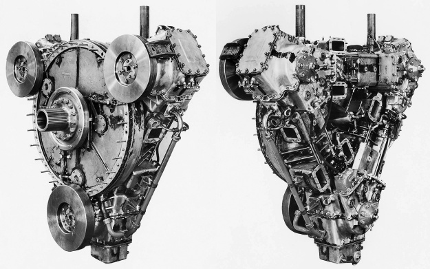
The Napier E130 three-cylinder test engine that validated the triangular engine arrangement. Each of the engine’s crankshafts had a flywheel on the drive end (left). The six intake chamber openings are visible on the free (non-drive) end (right). Note the vertical coolant pipes on top of the engine. (Napier/NPHT/IMechE images)

In 1944, the British Admiralty desired to increase the survivability of the Motor Torpedo Boat (MTB). One of the main issues was that MTBs used gasoline engines. Gasoline liquid is highly flammable, and gasoline vapor is highly explosive. MTB safety would be improved if a switch to diesel engines could be made. Diesel fuel has non-explosive characteristics and a much higher flashpoint than gasoline. However, at the time, there were no suitable diesel engines to power MTBs.

Around 1945, Napier and other companies submitted proposals to the Admiralty for a light-weight, powerful, and compact 18-cylinder diesel engine. Napier’s new engine carried the company designation E130, and the design was influenced by their experience with the Junkers Jumo diesel engines, their work on the Culverin and Cutlass, and analyses of other Jumo six-cylinder engines captured during World War II. However, there is no mention of the Junkers Jumo 223 contributing to Napier’s engine design. In early 1946, the Admiralty selected the Napier design and issued a developmental contract that covered the construction of one single-cylinder test engine, one three-cylinder test engine, and six prototype 18-cylinder engines.
Napier-Deltic-drive-end-section

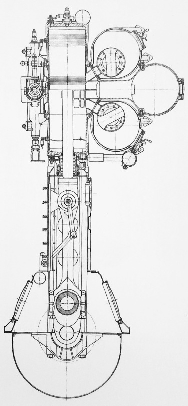
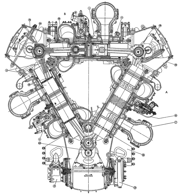
Section drawing from the drive end of a Deltic engine. The air chamber surrounds the intake end of the cylinder, and the exhaust manifolds are mounted to the outer sides of the engine. Note the rotation of the crankshafts. (Napier/NPHT/IMechE image)

Napier’s liquid-cooled, two-stroke engine used opposed-pistons, a design feature that eliminated many parts, required no cylinder head, improved thermal efficiency, and resulted in more power for a given size and weight. In an opposed-piston engine, each cylinder has two pistons that move toward each other to form a single combustion space near the center of the cylinder. Ports in the cylinder wall that are covered and uncovered by the pistons bring in air and allow exhaust gases to escape. The most unusual aspect of Napier’s design was that the engine was formed as an inverted triangle, with a crankshaft at each corner. Because of its triangular structure, the name Deltic was selected in reference to the Greek letter Delta, and the 18-cylinder engine was known as the Deltic D18 (or just 18). The triangular design resulted in a compact engine with a very rigid structure.

Design work on the Napier Deltic started under Ben Barlow, George Murray, and Ernest Chatterton, Chief Engineer of the Piston Engine Division at Napier. The project was initially overseen by Henry Nelson, with Herbert Sammons taking over in 1949. The Deltic engine formed an equilateral triangle with each of its three cylinder banks angled at 60 degrees. Cast aluminum crankcase housings were at each corner of the triangle, with the lower crankcase incorporating an oil sump and also serving as the engine’s base. Each cast aluminum cylinder bank was sandwiched between two crankcases via through bolts. The monobloc cylinder banks were identical, as were the upper two crankcases. However, various ancillary components were installed according to the casting’s position on the complete engine.
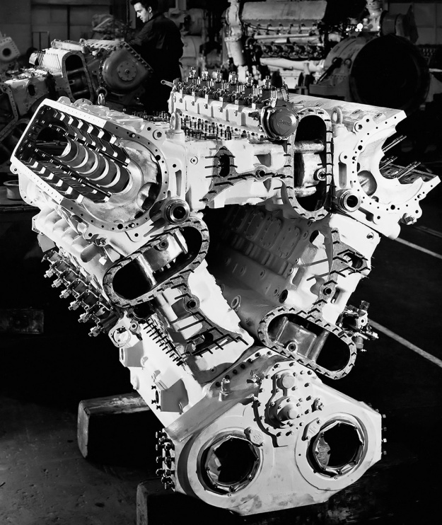
Napier-Deltic-18-Triangle-Case

The assembled cylinder banks and crankcases of an 18-cylinder Napier Deltic engine seen from the free end. Note the open space between the cylinder banks. The stadium (oval) ports are to the air chambers. The bushings visible in the upper crankcases, at the triangle’s corners, supported the shafts that drove the blower. (Napier/NPHT/IMechE image)

The forged-steel cylinder wet liners were open-ended and had a chrome-plated bore to reduce wear. Part of the bore was etched with small dimples to retain lubricating oil and reduce piston ring wear. The liner was approximately 32 in (813 mm) long and protruded some distance into the crankcases. The ends of the liner were notched to allow clearance for the swinging connecting rods. Near one end of the liner were 14 intake ports with a tangential entry to impart a swirling motion of the incoming air. The swirling air helped scavenge the cylinder through the nine exhaust ports near the other end of the liner. In each cylinder, one piston would cover and uncover the intake ports while the other piston would do the same for the exhaust ports. The exhaust ports were uncovered (opened) 34.5 degrees before the intake ports. Both sets of ports were uncovered (open) for 101.5 degrees, and the intake ports were uncovered (open) for 5.5 degrees after the exhaust ports were covered (closed). The placement of the intake and exhaust ports at opposite ends of the cylinder liner allowed for uniflow scavenging of the cylinder. The liners were shrink-fitted into the cylinder banks and secured by an annular nut on the intake side.

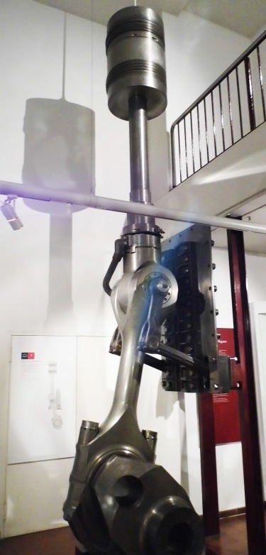
The two-piece pistons consisted of a cast aluminum outer body and a forged Y-alloy (nickel-aluminum alloy) inner member that held the wrist pin. The inner member was heat-shrunk to the outer piston body and secured by a large circlip. Oil flowed between the two pieces to cool the piston. Three compression rings were positioned just below the piston crown, and two oil scraper rings were located near the bottom of the piston skirt. The pistons were attached to fork-and-blade connecting rods, with the exhaust pistons mounted to the forked rods and the intake pistons mounted to the blade rods. The opposed pistons created a compression ratio of 17.5 to 1 (some sources say 15 to 1).
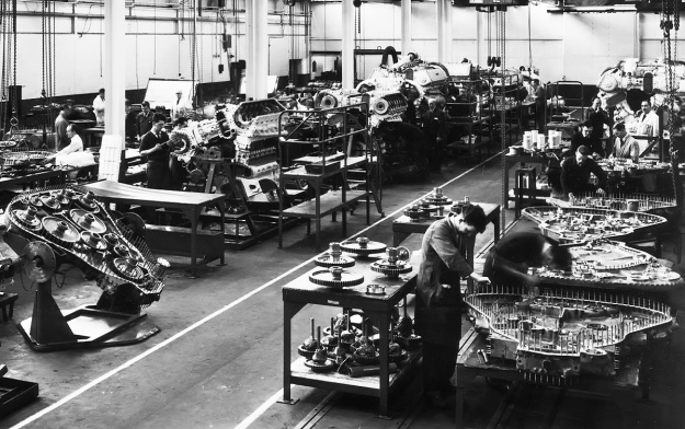
Napier-Deltic-assembly

Napier Deltic engine assembly, with phasing gear housings being built up in the lower right. At left is a completed phasing gear housing; note the two idler gears connecting the lower crankshaft to the central output shaft. Toward the center are Deltics in various stages of assembly. A completed engine without its blower installed is in the upper right. Note the opening in the center of the engine. (Napier/NPHT/IMechE image)

A two-piece phasing gear housing at the drive end of the engine contained the gears that connected the crankshafts to the main output shaft. The main output shaft was usually located at the center of the engine, but different phasing gear housings allowed for different output shaft locations. Each crankshaft was coupled to its drive gear via a short, flexible quill shaft. When viewed from the free (non-drive) end of the engine, the upper two crankshafts rotated clockwise and were connected to the main output shaft via one idler gear. The lower crankshaft rotated counterclockwise and was connected to the main output shaft via two idler gears. The idler gears could be repositioned to reverse the rotation of the output shaft. Each crankshaft was supported in its crankcase by seven main bearings, and each main bearing cap was secured by four studs and two transverse bolts. The crankshafts were phased so that the exhaust piston in each cylinder led the intake piston by 20 degrees. The reverse rotation of the lower crankshaft, and the crankshaft phasing was devised by Herbert Penwarden from the Admiralty Engineering Laboratory.

Via a quill shaft and bevel gears, each crankshaft also drove a camshaft for the fuel injection pumps. The camshaft was located in a housing bolted to the outer side of each cylinder bank, near its center. Each camshaft operated six fuel injection pumps, and each pump fed fuel to two injectors per cylinder. The timing of the pumps changed depending on engine RPM. The upper two crankshafts drove separate flexible drive shafts for the blower (weak supercharger). The driveshafts were positioned at the upper, inner corners of the engine triangle. They led to the opposite end of the engine and powered a single-stage, double-sided centrifugal blower. The impeller was 15.5 in (394 mm) in diameter and rotated at 5.72 times crankshaft speed, creating 7.8 psi of boost (.53 bar). The pressurized air from the blower was fed into a chamber that extended through each cylinder bank and that surrounded the intake ports in the cylinder liner. Exhaust gases were collected via a water-cooled manifold that attached to the outer side of each cylinder bank. The lower crankshaft drove a flexible drive shaft to power the engine’s two oil and two water pumps.

Napier-Deltic-T18-37K-sections-display

Basic sections of the Deltic (T18-37K) marine engine. From left to right are the blower section (turbo-blower in this case), D18-cylinder engine section, phasing gear housing, and the bi-directional gearbox. The Deltic was a powerful diesel engine for its size and weight. (Napier/NPHT/IMechE image)

When viewing the engine from the free end, the cylinder banks were designated as follows: left was Bank A; upper, horizontal was Bank B; and right was Bank C. The crankshafts were designated as follows: upper left was Crankshaft AB, upper right was Crankshaft BC, and lower was Crankshaft CA. The cylinder rows were numbered with Bank 1 at the free end, and subsequent banks were numbered consecutively with Bank 6 at the drive end. The Deltic D18’s firing order was Bank C cylinder 1 (C1), A6, B1, C5, A1, B5, C3, A5, B3, C4, A3, B4, C2, A4, B2, C6, A2, and B6.

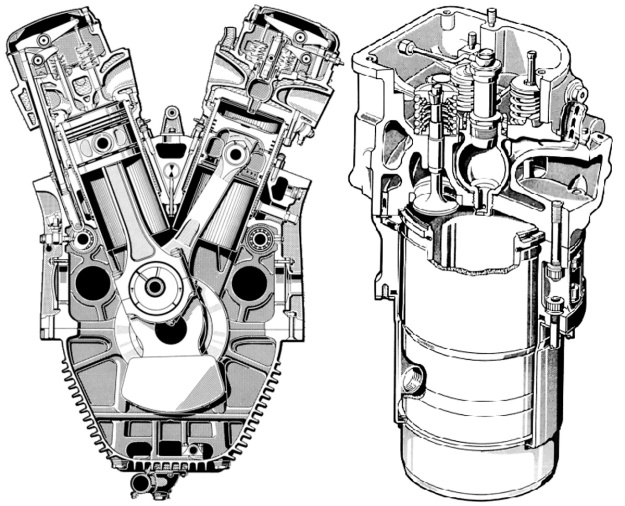
The Napier Deltic had a 5.125 in (130 mm) bore and a 7.25 in (184 mm) stroke (x2). This gave each cylinder a displacement of 299 cu in (4.9 L), and the 18-cylinder engine displaced 5,384 cu in (88.2 L). The bare engine (without the bi-directional marine gearbox) had a maximum, 15-minute output of 2,730 hp (2,036 kW) at 2,000 rpm with a specific fuel consumption (sfc) of .380 lb/hp/hr (231 g/kW/h). The Deltic’s continuous rating was 2,035 hp (1,517 kW) at 1,700 rpm with a sfc of .364 lb/hp/hr (221 g/kW/h). With the bi-directional gearbox, the engine produced 2,500 hp (1,864 kW) at 2,000 rpm with a sfc of .415 lb/hp/hr (252 g/kW/h) and 1,875 hp (1,398 kW) at 1,700 rpm with a sfc of .395 lb/hp/hr (240 g/kW/h). The Deltic D18 was 105 in (2.67 m) long, 71.25 in (1.81 m) wide, and 80 in (2.03 m) tall. The bi-directional gearbox added another 36 in (.91 m). The engine weighed 8,860 lb (4,018 kg) without the bi-directional gearbox and 10,500 lb (4,763 kg) with it.

The single-cylinder test engine was designed from October to December 1946, with the three-cylinder engine following from January to May 1947. Testing of these engines started as soon as construction was completed. The three-cylinder engine represented just one row of a Deltic engine, but it demonstrated the validity of the components used in the triangular arrangement.
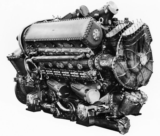
Napier-Deltic-D18-E130-Prototype

Free end of the 2,500 hp (1,864 kW) Deltic D18-1 (E130) prototype engine. Note the two intakes, one for each side of the double-sided blower. Each cylinder bank had two, large exhaust manifolds. The transverse bolts threaded into the main bearings can be seen on the side of the upper crankcase. (Napier/NPHT/IMechE image)

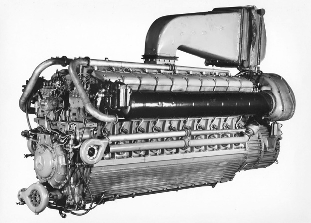
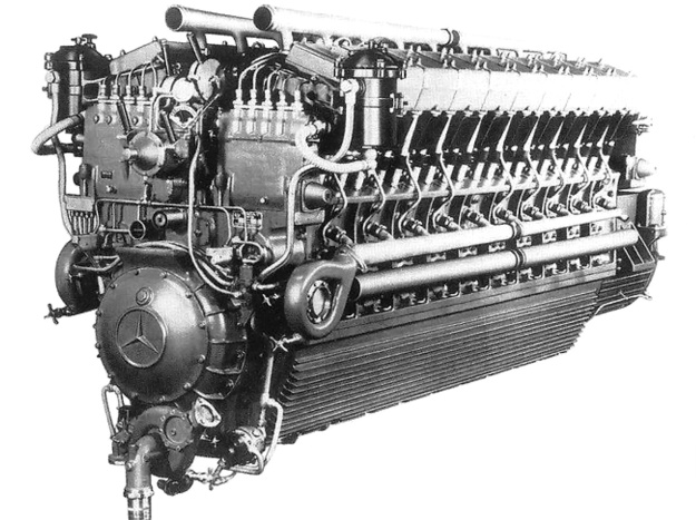
The first 18-cylinder Deltic Series I engine was assembled by March 1950. The engine was soon to be tested at Napier’s works in Acton, England; however, a cable broke as the engine was being mounted to the stand. It fell on the stand, damaging the engine and the test stand. Repairs were made, and engine began testing in April 1950. The 18-cylinder Deltic fired a cylinder every 20 degrees of crankshaft rotation, which resulted in smooth, nearly-constant output torque. Engine idle was around 600 rpm, and the Deltic demonstrated a gross mechanical efficiency of 85.5% at 2,000 rpm. In late 1951, two Deltics were installed in place of the three Mercedes-Benz MB 501 V-20 engines in a former German E-boat S-212 (redesignated Fast Patrol Boat P5212). By January 1952, the originally-contracted six Deltic D18 engines had been built. In 1953, an Admiralty 1,000-hr type test was completed and indicated the engine could run 2,000 hours between overhauls.

By 1954, Napier was offering a commercial version of the Deltic D18 Series I (E169). This was basically a de-rated engine. The commercial engine produced 1,900 hp (1,417 kW) at 1,500 rpm with a sfc of .363 lb/hp/hr (221 g/kW/h) and could operate for 5,000 hours between overhauls. In addition to a variety of marine applications, Deltic engines could also run power generation sets, water pumps, and be used to power traction motors for locomotives. Napier also built a nine-cylinder version with three banks of three cylinders. The Deltic 9 (E159/E165) displaced 2,692 cu in (44.1 L) and had a one-sided centrifugal blower but was otherwise of the same construction as the Deltic D18. It fired one cylinder for every 40 degrees of crankshaft rotation. Maximum output for the Deltic 9 was 1,250 hp (932 kW) at 2,000 rpm for the high-power version and 950 hp (708 kW) at 1,500 rpm for the commercial version. By late 1955, Deltic test and production engines had accumulated over 20,000 hours of operation.
Napier-Deltic-C18-5-Compound-Marine-Engine

The 5,500 hp (4,101 kW) compound Deltic C18 (E185) engine was the most powerful piston engine Napier ever built. Although it is covered, the intake can be seen in the upper part of the phasing gear housing. Exhaust was routed through the three-stage turbine, which powered the eight-stage compressor inside the engine’s triangle. (Napier/NPHT/IMechE image)

In 1956, Napier built a compound diesel engine known as the Deltic C18 (E185). Serious development of the C18 occurred after the Napier Nomad II compound diesel aircraft engine was cancelled in 1955. The Deltic C18 had an eight-stage (some sources say 12-stage, which was the same number of stages as used in the Nomad II) axial compressor positioned inside the engine triangle. The compressor was driven by a three-stage turbine, which was powered by the engine’s exhaust gases. The turbine was positioned in the normal blower position on the free end of the engine. A new phasing gear housing was constructed with an opening that allowed air into the center of the engine triangle and served as the inlet for the compressor. The Deltic C18 produced 5,500 hp (4,101 kW) at 2,000 rpm. The engine was 124 in (3.15 m) long, 65 in (1.65 m) wide, and 77 in (1.96 m) tall. The C18 weighed approximately 10,700 lb (4,853 kg). The engine was tested in 1957, but only one experimental C18 was built. While undergoing power tests, the engine was intentionally pushed beyond its limits until a connecting rod failed at 5,600 hp (4,176 kW). The rod came through the crankcase, but the damage was never repaired due to the Navy’s increased focus on gas turbine engines.

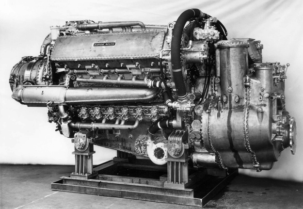
By 1956, Napier had introduced some minor changes as the Series II Deltic engines, but one major change was the addition of a turbo-blower. These engines were known as turbo-blown, and they were designated as the Deltic T18 (E171/E239). Exhaust gases were collected and fed into an axial-flow turbine mounted behind the blower. The turbine wheel was 18.04 in (458 mm) in diameter and helped turn the blower via a geared shaft. The turbine wheel turned at .756 times the speed of the blower impeller. The blower was still driven by the upper crankshafts, but it now turned at 8.266 times crankshaft speed. The turbo-blower created 19 psi (1.31 bar) of boost. The piston was redesigned and consisted of three-pieces: a Hidural 5 (copper alloy) crown that screwed onto an aluminum skirt to form the outer body, and a Y-alloy (nickel-aluminum alloy) inner member that held the wrist pin. A third scraper ring was added to the piston skirt. The compression ratio was increased to 17.9 to 1, and the engine used one fuel injector per cylinder. The Deltic T18 had an output of 3,100 hp (2,312 kW) at 2,100 rpm and 2,400 hp (1,641 kW) at 1,800 rpm. SFC was .414 lb/hp/hr (252 g/kW/h) and .404 lb/hp/hr (246 g/kW/h) respectively. The engine was 118 in (3.00 m) long, 75 in (1.91 m) wide, and 84 in (2.13 m) tall. The T18 weighed around 13,630 lb (6,183 kg) with the bi-directional gearbox and 11,050 lb (5,012 kg) without it. The turbo-blown nine-cylinder Deltic T9 (E172/E198) produced 1,100 hp (820 kW) at 1,600 rpm.

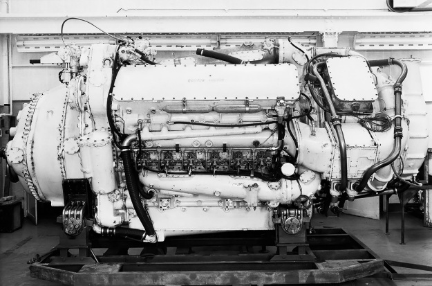
Napier-Deltic-T18-37K-Marine-Engine

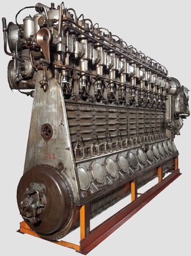
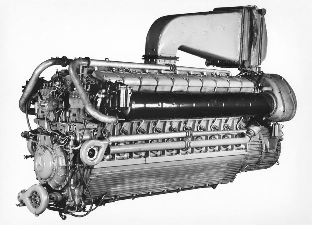
The 3,100 hp (2,312 kW) turbo-blown Deltic T18-37K (E239) engine was most widely used in Motor Torpedo Boats. Note the exhaust manifolds leading to the turbine with its large intake at the rear of the engine. The short duct connecting the blower to the upper cylinder bank is visible. (Napier/NPHT/IMechE image)

More changes were incorporated into the Series III engines, which also introduced charge-cooling with the Deltic CT18 (E263) in 1966. For the CT18, a single drive shaft passed through the center of the engine to deliver power from the phasing gear housing to the turbo-blower. The shaft turned at 5.16 times crankshaft speed, and both the blower impeller and turbine wheel were mounted to the drive shaft. The single-sided blower impeller was relocated to behind the turbine wheel. A water-filled aftercooler was mounted before each opening of the engine’s three air compartments. The aftercooler dropped the charge temperature from 259° F (126° C) to 144° F (62°C). Pistons were again redesigned, with the Hidural 5 (copper alloy) crown bolting to the aluminum skirt. For the Deltic CT18, power increased to 3,700 hp (2,759 kw) at 2,100 rpm with a sfc of .403 lb/hp/hr (245 g/kW/h) and 2,750 hp (2,051 kW) at 1,800 rpm with a sfc of .395 lb/hp/hr (240 g/kW/h). By 1968, further development had increased the output to 4,000 hp (2,983 kW) at 2,100 rpm with a sfc of .401 lb/hp/hr (244 g/kW/h) and 3,000 hp (2,237 kW) at 1,800 rpm with a sfc of .399 lb/hp/hr (243 g/kW/h). The CT18 weighed 15,382 lb (6,977 kg) with its bi-directional gearbox.

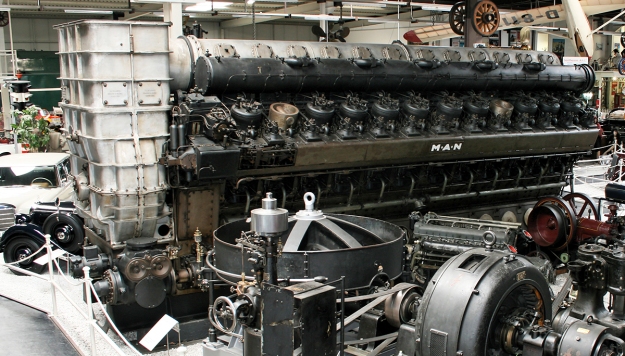
As Napier declined in the late 1960s, English Electric moved Deltic production to the newly acquired Paxman Engine Division. The General Electric Company (GEC, not related to the US company General Electric / GE) purchased English Electric in 1968. What was once Napier basically closed in 1969. In 1975, GEC reformed Paxman Engine Division as Paxman Diesels Limited. Paxman continued to support Deltic engines, developing the CT18 to 4,140 hp (3,087 kW) in 1978 and reworking the mechanically-blown Deltic 9 for production as the D9-59K (E280) in the early 1980s. The D9-59K was constructed almost entirely with non-ferrous (non-magnetic) parts for mine-sweeper duties. In 2000, MAN acquired what used to be Paxman, and Rolls-Royce was awarded a contract to support Deltic engines in 2001. The contract was carried through until 2012, but it is not clear if the contract was extended beyond that year.
Napier-Deltic-CT18-42K-Charge-Cooled-engine

A 3,700 hp (2,759 kw) charge-cooled and turbo-blown Deltic CT18-42K (E263) engine. The turbine is located between the engine and the blower. Note the large, square aftercooler in the air duct between the blower and the engine. (Napier/NPHT/IMechE image)

Deltic engines powered a number of various MTBs, including the Royal Navy’s Dark-class (18 produced). Two 3,100 hp (2,312 kW) Deltic C18 turbo-blown engines powered each Nasty-class / Tjeld-class fast patrol boat (total of 49 built), which were designed in 1959 and put in service in 1960. These boats served with the navies of Norway, the United States, Greece, Germany, and Turkey. The boats had a top speed of 52 mph (83 km/h), and some were in service until the 1990s. Deltic engines powered Ton-class minesweepers (over 100 built) as well as the pulse generators for other minesweepers. Deltics were still being installed in new military boats during the 1980s, with the 1,180 hp (880 kW) Deltic T9-powered Hunt-class minesweepers (13 built) still in service. A few commercial vessels were also powered by Deltic engines—the largest installation was four 1,850 hp (1,380 kW) engines for the 513.5-ft (156.5-m) ore carrier Bahama King in 1958.

In 1955, two 1,650 hp (1,230 kW) Deltic D18-12 (E158) engines were used in the English Electric DP1, a prototype diesel-electric locomotive. The engines powered six English Electric EE829-1A traction motors that gave the locomotive 50,000 lbf (222.4 kN) of tractive effort. The DP1 proved successful, resulting in 22 British Rail Class 55 locomotives powered by Deltic D18-25 (E169) engines being built in the early 1960s. Called Deltics, these locomotives could exceed 110 mph (177 km/h) and were in service until the early 1980s. One 1,100 hp (919 kW) Deltic T9-29 (E172) engine was used in each of the smaller British Rail Class 23 locomotives, known as Baby Deltics. The engine powered four English Electric traction motors that gave the locomotive 47,000 lbf (209.1 kN) of tractive effort. The Baby Deltics entered service in 1959, but they were not as successful as their bigger counterparts due to shorter runs and frequent stops. All Baby Deltics were withdrawn from service by 1971.
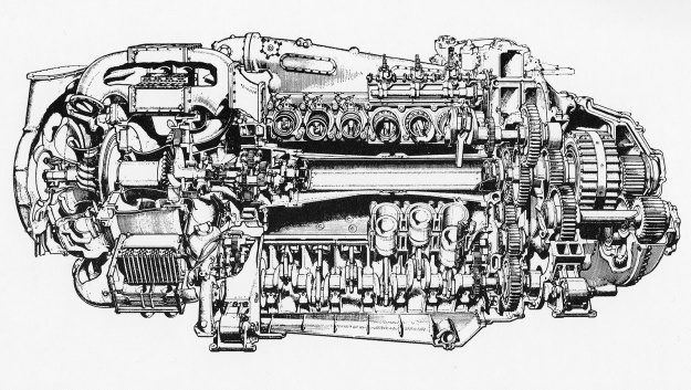
Napier-Deltic-CT18-Charge-Cooled-cutaway

Cutaway view of a Deltic CT-18 charge-cooled and turbo-blown engine. Note the shaft through the center of the engine that powered the turbo-blower from the phasing gear. (Napier/NPHT/IMechE image)

Other Deltic designs included a 735 hp (548 kW) inline six-cylinder (E164/E197) with one bank of six cylinders and a 1,420 hp (1,059 kW) 15-cylinder (E162) with three banks of five cylinders, but these engines were not built. A 24-cylinder square engine (E260) with four crankshafts and four banks of six cylinders was also designed for an output of 5,400 hp (4,027 kW). The square engine design had much more in common with the Deltic than the Jumo 223, but it was not constructed. Including the nine-cylinder version, over 600 Deltic engines were made. A number of Deltic engines survive. Some are still operational in preserved boats or locomotives, allowing the unusual roar of the triangular two-stroke Deltic to still be heard. Others engines are in various museums, and a few are privately owned.

Note: In some cases, the Napier E number is one example of the type, with additional E numbers existing for similar engines with different configurations (marine vs rail applications). Around 100 E numbers were assigned to various Deltic designs.
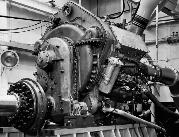
Napier-Deltic-T9-33-Locomotive-Rraction-Engine

A 1,250 hp (932 kW) turbo-blown nine-cylinder Deltic T9-33 (E198) under test at Napier’s factory in Acton. The engine was similar to those used in the Baby Deltic Locomotives. Note the low position of the output shaft. (Napier/NPHT/IMechE image)

Sources:
– “The Napier Deltic Diesel Engine” by Ernest Chatterton, SAE Transactions Vol 64 (1956)
Opposed Piston Engines by Jean-Pierre Pirault and Martin Flint (2010)
Course Notes on the Deltic Engine Type T18-37K by D. Napier & Son Ltd. (December 1967)
– “Development of the Napier Deltic Charge Cooled Engine” by R. P. Taylor and C. H. Davison, Proceedings of the Institution of Mechanical Engineers Vol 183 (1968–69)
By Precision Into Power by Alan Vessey (2007)
Napier Powered by Alan Vessey (1997)
https://www.ptfnasty.com/ptfDeltic.html
http://www.npht.org/deltic/4579702653
Fairbanks Morse Diamond stress test

Fairbanks Morse Diamond Opposed-Piston Marine Engine

By William Pearce

In the early 1930s, Fairbanks Morse & Company (FM) took an interest in two-stroke, opposed-piston, diesel engines, and they acquired a license to produce a design originally developed by the German firm Junkers. In an opposed-piston engine, each cylinder has two pistons that move toward each other to form a single combustion space near the center of the cylinder. Ports in the cylinder wall bring in air and allow exhaust gases to escape. The opposed-piston design offers some advantages over conventional engines by having fewer parts, no cylinder head, improved thermal efficiency, and more power for a given size and weight.

Fairbanks Morse 38E 5.25

The Fairbanks Morse 38E5-1/4 had characteristics common to other 38-series opposed-piston engines and was a basis for the 24-cylinder Diamond engine. (Fairbanks Morse image)

FM used the information acquired from Junkers to develop its own line of opposed-piston diesel engines. One of the first opposed-piston engines produced by FM was the Model 38, which was a two-stroke vertical engine with two crankshafts linked initially by a gear train, which was soon replaced by a drive chain. In its 38A8 form, the engine had eight cylinders with an 8 in (203 mm) bore and a 10 in (254 mm) stroke (x2). The 38A8 displaced 8,042 cu in (131.8 L) and produced 1,200 hp (895 kW) at 720 rpm. In December 1934, the United States Navy ordered eight 38A8 engines—four each for the USS Plunger (SS-179) and USS Pollack (SS-180) Porpoise-class submarines. Problems with the 38A8s led to a redesign, ultimately creating the 38D8 engine.

In 1937, FM upgraded the 38D8 to produce more power. The drive chain linking the two crankshafts was replaced with a vertical shaft and bevel gears. The bore was increased by .125 in (3 mm) to 8.125 in (206 mm), and cylinders were added to create 9- and 10-cylinder engines. The new engine was designated 38D8-1/8. With the larger bore and 10 cylinders, the engine displaced 10,370 cu in (169.9 L) and produced 1,600 hp (1,193 kW) at 720 rpm. Approximately 1,650 38D8-1/8 engines were built during World War II. The engine was eventually offered with 4, 5, 6, 8, 9, 10, and 12 cylinders and with or without turbocharging. Although changes have been incorporated over the years, the FM OP 38D8-1/8 remains in production today.

In 1939, FM developed a scaled-down version of the 38D to be used as an auxiliary power unit. This engine was designated 38E5-1/4, and it had a 5.25 in (133 mm) bore and a 7.25 in (184 mm) stroke (x 2). The engine was available with three, five, or seven cylinders. The 7-cylinder 38E5-1/4 displaced 2,197 cu in (36.0 L) and produced 467 hp (348 kW) at 1,200 rpm. Around 630 38E5-1/4 engines were built during World War II.

Fairbanks Morse Diamond sectional

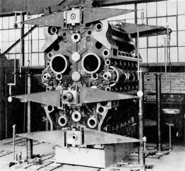
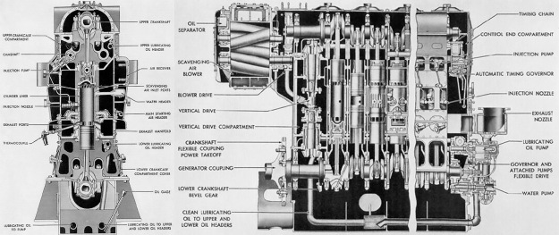
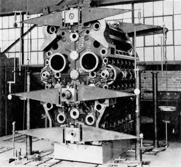
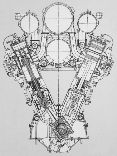
Sectional drawing of the Fairbanks Morse Diamond engine shows the arrangement of its four crankshafts and opposed-piston cylinders. The output shaft is drawn with a six-hole flange and is just below the center of the engine. (Fairbanks Morse image)

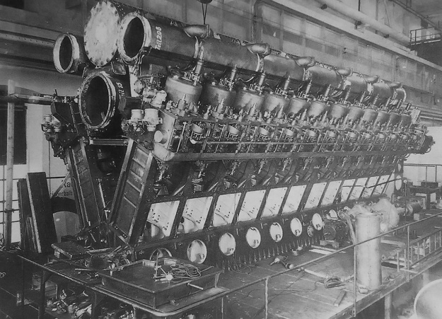
Based on the development of the Model 38-series, the Navy approached FM in early 1940 with a request to design and build a 3,000 hp (2,237 kW) opposed-piston engine for submarine use. With the prospect of war looming on the horizon, FM quickly went to work on the new engine design and assigned Robert Beadle as the program’s head engineer. The engine borrowed the basic cylinder design from the 38E5-1/4, but the engine was of a diamond configuration with a crankshaft at each corner. This gave the engine four banks of six opposed-piston cylinders resulting in a total of 24 cylinders.

The FM Diamond engine was of welded steel construction, with the crankcase and four cylinder banks forming a single unit. The lower and upper bank angles were 60 degrees. The left and right bank angles were 120 degrees. A cover concealed each crankshaft, and crankshaft removal allowed access to the cylinder liners. Each forged steel crankshaft was supported by seven main bearings.

The fork-and-blade connecting rods were made from steel forgings and then polished for added strength. The rods were drilled to deliver oil from the crankshaft to the wrist pin and to the underside of the piston crown for cooling. The pistons had a concave crown and formed a somewhat hemispherical combustion space when the two pistons came together. The two-piece pistons were made of cast steel with an aluminum wrist pin carrier.

The cylinder liners were made of forged steel and had a chrome-plated bore. A water jacket was pressed on each liner’s center section, where combustion occurred. Intake and exhaust ports were cast into the cylinder liners, and movement of the pistons covered and uncovered these ports. The upper and lower crankshafts were connected to the “exhaust” pistons that controlled the exhaust ports, and the left and right crankshafts operated the “intake” pistons controlling the intake ports. The crankshafts were phased so that the exhaust pistons (upper and lower crankshafts) led the intake pistons (left and right crankshafts) by about 15 degrees. This allowed for good cylinder scavenging, with the exhaust ports being uncovered (open) before the intake ports and with the intake ports remaining uncovered (open) for a short time after the exhaust ports had been covered (closed).

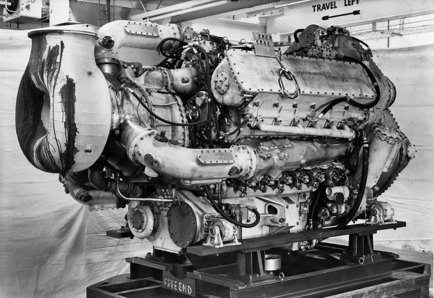
Fairbanks Morse Diamond stress test

The welded crankcase of the Diamond engine undergoing stress tests before final assembly. The crankshafts and pistons are installed, and the output shaft is visible just below the engine’s center. Note the mounting pads at the top of the engine for the two centrifugal blowers. The blowers fed air into the center of the engine via the two large holes. (Fairbanks Morse image)

The upper crankshaft drove two gear-driven centrifugal blowers (weak superchargers) mounted to the drive end of the engine. The blowers forced air into a central chest inside of the engine diamond. Four compartments, one for each bank, surrounded the intake end of the cylinders and supplied air from the chest. The intake ports in the cylinder liner were tangentially cast so that the incoming air initiated a swirling motion as it entered the cylinder. This swirl helped scavenge the cylinder of exhaust gases and mix the fuel once it was injected. The exhaust end of each cylinder was surrounded by an open passageway that led outside of the engine. A water-cooled exhaust manifold made of welded steel was attached to the side of the engine and collected the exhaust gases.

Each of the left and right crankshafts drove an upper and lower camshaft. The camshafts actuated individual fuel injector pumps for the single fuel injector in each cylinder. The fuel injector was located in the center of the cylinder liner. Fuel was injected into the cylinder at approximately 3,000 psi (207 bar). All of the crankshafts were geared to a single output power shaft, located 13.75 in (349 mm) below the engine’s absolute center. The left, right, and lower crankshafts were each connected to the output shaft via one idler gear. The upper crankshaft was geared to the output shaft through three idler gears. The gears used herringbone teeth. Pressurized air fed through internal piping was used to start the engine.

In designing the engine, FM engineers spent over 6,000 man-hours on torsional vibration calculations alone. The FM Diamond engine was completed in 1942. It had a 5.25 in (133 mm) bore and a 7.25 in (184 mm) stroke (x 2). The engine’s total displacement was 7,533 cu in (123.4 L). The engine was 120 in (3.05 m) tall and 72 in (1.83 m) wide when bare, or 141.5 in (8.73 m) tall and 79.25 in (24.16 m) wide when mounted to its steel stand. Its length was approximately 90 in (27.43 m).

During testing, the Diamond engine produced 3,000 hp (2,237 kW) at 1,500 rpm with 6.88 psi (.47 bar) of scavenging pressure. At this power, the specific fuel consumption was .420 lb/hp/hr (255 g/kW/h). However, the engine experienced constant issues with excessive wear and carbon build-up in the intake and exhaust ports. The program was cancelled at the end of World War II. At the time of cancellation, the experimental Diamond engine had accumulated 2,032 hours of test running.

Fairbanks Morse Diamond test stand

The engine undergoing bench tests. Note the two centrifugal blowers providing air for scavenging and combustion. (Fairbanks Morse image)

Sources:
– “Development of Diamond Opposed-Piston Diesel Engine” by R. H. Beadle (discussion of “The Napier Deltic Diesel Engine”) SAE Transactions Vol 64 (1956)
Opposed Piston Engines by Jean-Pierre Pirault and Martin Flint (2010)
Diesels for the First Stealth Weapon: Submarine Power 1902–1945 by Lyle Cummins (2007)
Submarine Main Propulsion Diesels: NavPers 16161 (June 1946)
http://www.dieselduck.info/machine/01%20prime%20movers/fairbanks_morse/fairbanks_morse.htm

Isotta Fraschini Asso 750 front

Isotta Fraschini W-18 Aircraft and Marine Engines

By William Pearce

In late 1924, the Italian firm Isotta Fraschini responded to a Ministero dell’Aeronautica (Italian Air Ministry) request for a 500 hp (373 kW) aircraft engine by designing the liquid-cooled, V-12 Asso 500. Designed by Giustino Cattaneo, the Asso 500 proved successful and was used by Cattaneo as the basis for a line of Asso (Ace) engines developed in 1927. Ranging from a 250 hp (186 kW) inline-six to a 750 hp (559 kW) W-18, the initial Asso engines shared common designs and common parts wherever possible.

Isotta Fraschini Asso 750 front

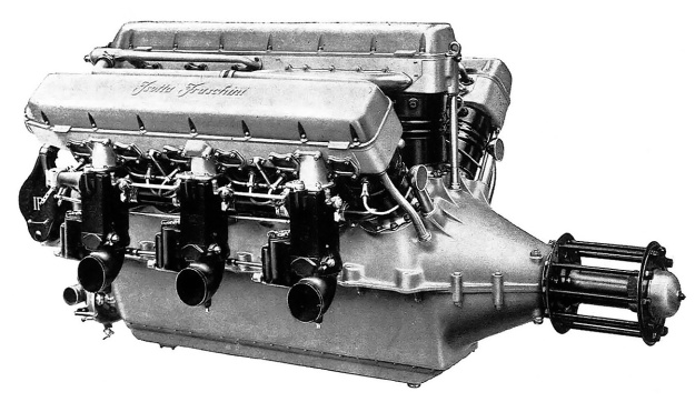
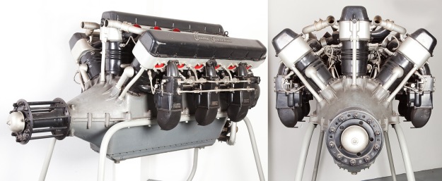
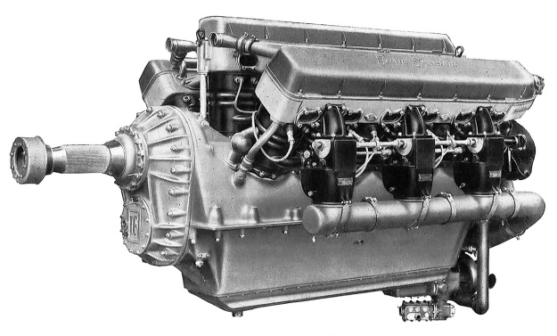
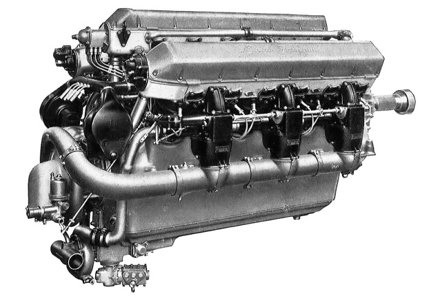
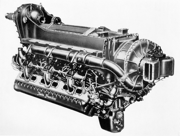
The direct drive Isotta Fraschini Asso 750 was the first in a series of 18-cylinder engines that would ultimately be switched to marine use and stay in some form of production for over 90 years.

The Isotta Fraschini Asso 750 W-18 engine consisted of three six-cylinder banks mounted to a two-piece crankcase. The center cylinder bank was in the vertical position, and the two other cylinder banks were spaced at 40 degrees from the center bank. The cylinder bank spacing reduced the 18-cylinder engine’s frontal area to just slightly more than a V-12.

The Asso 750’s crankcase was split horizontally at the crankshaft and was cast from Elektron, a magnesium alloy. A shallow pan covered the bottom of the crankcase. The six-throw crankshaft was supported by eight main bearings. On each crankshaft throw was a master rod that serviced the center cylinder bank. Articulating rods for the other two cylinder banks were mounted on each side of the master rod. A double row ball bearing acted as a thrust bearing on the propeller shaft and enabled the engine to be installed as either a pusher or tractor.

The individual cylinders were forged from carbon steel and had a steel water jacket that was welded on. The cylinders had a closed top with openings for the valves. The monobloc cylinder head was mounted to the top of the cylinders, with one cylinder head serving each bank of cylinders. The cylinder compression ratio was 5.7 to 1. The cylinder head was made from cast aluminum and held the two intake and two exhaust valves for each cylinder. The valves were actuated by dual overhead camshafts, with one camshaft controlling the intake valves and the other camshaft controlling the exhaust valves (except for the center bank). A single lobe on the camshaft acted on a rocker and opened the two corresponding valves for that cylinder. The camshafts for each cylinder bank were driven at the rear of the cylinder head. One camshaft of the cylinder bank was driven via beveled gears by a vertical drive shaft, and the second camshaft was geared to the other driven camshaft. The valve cover casting was made from Elektron.

Isotta Fraschini Asso 750 RC35 crankcase

The cylinder row, upper crankcase, and cylinder head (inverted) of an Asso 750 RC35 with gear reduction. The direct drive Asso 750 was similar except for the shape of the front (right side) of the crankcase. Note the closed top cylinders. The small holes between the studs in the cylinder top were water passageways that communicated with ports on the cylinder head.

Three carburetors were mounted to the outer side of each outer cylinder bank. The intake and exhaust ports of the outer cylinder banks were on the same side. The intake and exhaust ports of the center cylinder bank were rather unusual. When viewed from the rear, the exhaust ports for the rear three cylinders of the center bank were on the right, and the intake ports were on the left. The front three cylinders were the opposite, with their exhaust ports on the left and their intake ports on the right. This configuration gave the cylinders for the center bank crossflow heads, but it also meant that each camshaft controlled half of the intake valves and half of the exhaust valves. A manifold attached to the inner side of the left cylinder bank collected the air/fuel mixture that had flowed through passageways in the left cylinder head and delivered the charge to the rear three cylinders of the center bank. The right cylinder bank had the same provisions but delivered the mixture to the front three cylinders of the center bank. Presumably, the 40-degree cylinder bank angle did not allow enough room to accommodate carburetors for the middle cylinder bank.

The two spark plugs in each cylinder were fired by two magnetos positioned at the rear of the engine and driven by the camshaft drive. From the rear of the engine, the firing order was 1 Left, 6 Center, 1 Right, 5L, 2C, 5R, 3L, 4C, 3R, 6L, 1C, 6R, 2L, 5C, 2R, 4L, 3C, and 4R. A water pump positioned below the magnetos circulated water into a manifold along the base of each cylinder bank. The manifold distributed water into the water jacket for each individual cylinder. The water flowed up through the water jacket and into the cylinder head. Another manifold took the water from each cylinder head to the radiator for cooling. Starting the Asso 750 was achieved with an air starter.

Motore Isotta Fraschini Asso 750

Two views of the direct drive Asso 750 displayed at the Museo nazionale della scienza e della tecnologia Leonardo da Vinci in Milan. Note the three exhaust stacks visible on the center cylinder bank. The front image of the engine illustrates the lack of space between the cylinder banks, which were set at 40 degrees. (Alessandro Nassiri images via Wikimedia Commons)

The Isotta Fraschini Asso 750 had a bore of 5.51 in (140 mm), a stroke of 6.69 in (170 mm), and a total displacement of 2,875 cu in (47.1 L). The original, direct drive Asso 750 produced 750 hp (599 kW) at 1,600 rpm, and weighed 1,279 lb (580 kg). An improved version of the Asso 750 was soon built that produced 830 hp (619 kW) at 1,700 rpm and 900 hp (671 kW) at 1,900 rpm. This engine weighed 1,389 lb (630 kg). The direct drive Asso 750 was 81 in (2.06 m) long, 40 in (1.02 m) wide, and 42 in (1.07 m) tall.

A version of the Asso 750 with a spur gear reduction for the propeller was developed and was sometimes referred to as the Asso 850 R. Available gear reductions were .667 and .581, and the gear reduction resulted in the crankshaft having only seven main bearings. The Asso 850 R produced 850 hp (634 kW) at 1,950 rpm, and weighed 1,455 lb (660 kg). This engine was also further refined and given the more permanent designation of Asso 750 R. The 750 R had a .658 gear reduction. The engine produced 850 hp (634 kW) at 1,800 rpm and 930 hp (694 kW) at 1,900 rpm. The Asso 750 R was 83 in (2.12 m) long and weighed 1,603 lb (727 kg).

Isotta Fraschini Asso 750 rc35 front

Front view of the Asso 750 RC35. The gear reduction required new upper and lower crankcase halves and a new crankshaft, but the other components were interchangeable with the direct drive engine.

Around 1933 the Asso 750 R engine was updated to incorporate a supercharger. The new engine was designated Asso 750 RC35. The “R” in the engine’s designation meant that it had gear reduction (Riduttore de giri); the “C” meant that it was supercharged (Compressore); and the “35” stood for the engine’s critical altitude in hectometers (as in 3,500 meters). The engine’s water pump was moved to a new mount that extended below the oil pan. The supercharger was mounted between the water pump and the magnetos, which were moved to a slightly higher location. The supercharger was meant to maintain sea level power up to a higher altitude, and it provided .29 psi (.02 bar) of boost up to 11,483 ft (3,500 m). The Asso 750 RC35 produced 870 hp (649 kW) at 1,850 rpm at 11,483 ft (3,500 m). The engine was 87 in (2.20 m) long, 41 in (1.03 m) wide, 48 in (1.21 m) tall, and weighed 1,724 lb (782 kg).

In 1928, Isotta Fraschini designed a larger, more powerful engine that had both its bore and stroke increased by .39 in (10 mm) over that of the Asso 750. The larger engine was developed especially for the Macchi M.67 Schneider Trophy racer. The M.67’s engine was initially designated Asso 750 M (for Macchi) but was also commonly referred to as the Asso 2-800. The “2” designation was most likely applied because the engine was a “second generation” and differed greatly from the original Asso 750 design.

Isotta Fraschini Asso 750 rc35 rear

The single-speed supercharger on the Asso 750 RC35 is illustrated in this rear view. Note the relocated and new mounting point for the water pump. The supercharger forced-fed air to the engine’s six carburetors.

The Asso 2-800 had a bore of 5.91 in (150 mm), a stroke of 7.09 in (180 mm), and a total displacement of 3,434 cu in (57.3 L). The engine used new crossflow cylinder heads and a new crankcase. The cylinder heads had intake ports on one side and exhaust ports on the other. Air intakes for the engine were positioned behind the M.67’s spinner, with one intake on the left side for the left cylinder bank and two intakes on the right side for the center and right cylinder banks. Ducts delivered the air to special carburetors positioned between the cylinder banks. The modified engine also had a higher compression ratio and used special fuels. Under perfect conditions, the special Asso 2-800 engine produced up to 1,800 hp (1,342 kW), but it was rarely able to achieve that output. An output of 1,400 hp (1,044 kW) was more typical and still impressive. At speed, the Asso 2-800 in the M.67 reportedly made a roar like no other engine.

Isotta Fraschini made a commercial version of the larger engine, designated Asso 1000. With the same bore, stroke, and displacement as the Asso 2-800, the Asso 1000 is often cited as the engine powering the M.67. However, the Asso 1000 retained the same configuration and architecture as the Asso 750, except the Asso 1000 had a compression ratio of 5.3 to 1. Development of the Asso 1000 trailed slightly behind that of the Asso 750.

The direct drive Isotta Fraschini Asso 1000 produced 1,000 hp (746 kW) at 1,600 rpm and 1,100 hp (820 kW) at 1,800 rpm. The engine was 86 in (2.19 m) long, 42 in (1.06 m) wide, and 44 in (1.12 m) tall. The Asso 1000 weighed 1,764 lb (800 kg). Like with the original Asso 750, a gear reduction version was designed. This engine was sometimes designated as the Asso 1200 R. The gear reduction speeds available were .667 and .581. The Asso 1200 R produced 1,200 hp (895 kW) at 1,950 rpm and weighed 2,116 lb (960 kg).

Isotta Fraschini Asso 1000

The Isotta Fraschini Asso 1000 was very similar to the Asso 750. Note the intake manifolds between the cylinder banks, each taking the air/fuel mixture from one of the outer banks and feeding half of the center bank.

The Asso 750 and Asso 1000 engines were used in a variety of aircraft, but most of the aircraft were either prototypes or had a low production count. For the Asso 750, its most famous applications were the single engine Caproni Ca.111 reconnaissance aircraft (over 150 built) and the twin engine Savoia-Marchetti S.55 double-hulled flying boat. Over 200 S.55s were built, but only the S.55X variant was powered by the Asso 750. Twenty-five S.55X aircraft were built, and in 1933, 24 S.55X aircraft made a historic formation flight from Orbetello, Italy to Chicago, Illinois. The Asso 750 powered many aircraft to numerous payload and distance records. Six direct-drive Asso 1000 engines were used to power the Caproni Ca.90 bomber, which was the world’s largest landplane when it first flew in October 1929. The Ca.90 set six payload records on 22 February 1930.

Although not a complete success in aircraft, the Asso 1000 found its way into marine use as the Isotta Fraschini ASM 180, 181, 183 and 184 engines. ASM was originally written as “As M” and stood for Asso Marini (Ace Marine). The marine engines had water-cooled exhaust pipes and a reversing gearbox coupled to the propeller shaft. The Isotta Fraschini marine engines were used in torpedo boats before, during, and after World War II by Italy, Finland, Sweden, and Britain. Some of the engines and boats remained in service into the mid-1960s.

Isotta Fraschini ASM 184

The Isotta Fraschini ASM 184 engine with its large, water-cooled exhaust manifolds and drive gearbox. Note that the center bank only has its rear (left) cylinders feeding into the visible exhaust manifold. One of the two centrifugal superchargers can be seen at the rear of the engine. The engine is on display at the Museo Nicolis in Villafranca di Verona. (Stefano Pasini image)

The ASM 180 and 181 were developed around 1933, and produced 900 hp (671 kW) at 1,800 rpm. Refinement of the ASM 181 led to the ASM 183, which produced 1,150 hp (858 kW) at 2,000 rpm. Development of the ASM 184 started around 1940; it was a version of the ASM 183 that featured twin centrifugal superchargers mounted to the rear of the engine. The ASM 184 engine produced 1,500 hp (1,119 kW) at 2,000 rpm. Around 1950, production of the ASM 184 was continued by Costruzione Revisione Motori (CRM) as the CRM 184. In the mid-1950s, the engine was modified with fuel injection into the supercharger compressors and became the CRM 185. The CRM 185 produced 1,800 hp (1,342 kW) at 2,200 rpm.

CRM continued development of the W-18 platform and created a diesel version of the engine. Designated 18 D, the engine retained the same bore, stroke, and basic configuration as the Asso 1000 and earlier ASM engines. However, the 18 D was made of cast iron, had revised cylinder heads, and had a compression ratio of 14 to 1. The revised cylinder head was much taller and incorporated extra space between the valve springs and the valve heads. The valve stems were elongated, and a pre-combustion chamber was positioned between the valve stems and occupied the extra space in the head. Some versions of the engine have a fuel injection pump consisting of three six-cylinder distributors driven from the rear of the engine, while other versions have a common rail fuel system.

CRM 18 D engines

Four CRM 18 D engines, which can trace their heritage back to the Asso 1000. The three engines on the left use mechanical fuel injection with three distribution pumps. The engine on the right has a common fuel rail. Note the three turbochargers at the front of each engine. (CRM Motori image)

The exhaust gases for each bank were collected and fed through a turbocharger at the front of the engine (some models had just two turbochargers). Pressurized air from the turbochargers passed through an aftercooler and was then fed into two induction manifolds. Each of the manifolds had three outlets. The front and rear outlets were connected to the outer cylinder bank, and the middle outlet was connected to the center bank. For the center bank, induction air for the rear three cylinders was provided by the left manifold, and the front three cylinder received their air from the right manifold.

Various versions of the 18 D were designed, the most powerful being the 18 D BR3-B. The BR3-B had a maximum output of 2,367 hp (1,765 kW) at 2,300 rpm and a continuous output of 2,052 hp (1,530 kW) at 2,180 rpm. The engine had a specific fuel consumption of .365 lb/hp/hr (222 g/kW/h). The BR3-B was 96 in (2.45 m) long, 54 in (1.37 m) wide, 57 in (1.44 m) tall, and weighed 4,740 lb (2,150 kg) without the drive gearbox. CRM, now known as CRM Motori Marini, continues to market 18 D engines.

Isotta Fraschini Asso L180

Other than having a W-18 layout, the Isotta Fraschini L.180 did not share much in common with the Asso 750 or 1000. However, the two-outlet supercharger suggests a similar induction system to the earlier engines. Note the gear reduction’s hollow propeller shaft and the mounts for a cannon atop the engine.

In the late 1930s, Isotta Fraschini revived the W-18 layout with an entirely new aircraft engine known as the Asso L.180 (or military designation L.180 IRCC45). The Asso L.180 was an inverted W-18 (sometimes referred to as an M-18) that featured supercharging and a propeller gear reduction. The engine’s layout and construction were similar to that of the earlier W-18 engines. One source states the cylinder banks were spaced at 45 degrees. With nine power pulses for each crankshaft revolution, this is off from the ideal of having cylinders fire at 40-degree intervals (like the earlier W-18 engines) and may be a misprint. The crankshaft was supported by seven main bearings in a one-piece aluminum crankcase. The spur gear reduction turned at .66 crankshaft speed and had a hollow propeller shaft to allow an engine-mounted cannon to fire through the propeller hub. The single-speed supercharger turned at 10 times crankshaft speed.

The Isotta Fraschini L.180 had a 5.75 in (146 mm) bore and a 6.30 in (160 mm) stroke. The engine displaced 2,942 cu in (48.2 L) and had a compression ratio of 6.4 to 1. The L.180 had a takeoff rating of 1,500 hp (1,119 kW) at 2,360 rpm, a maximum output of 1,690 hp (1,260 kW) at 2,475 rpm at 14,764 ft (4,500 m), and a cruising output of 1,000 hp (746 kW) at 1,900 rpm at 14,764 ft (4,500 m). It is doubtful that the L.180 proceeded much beyond the mockup phase.

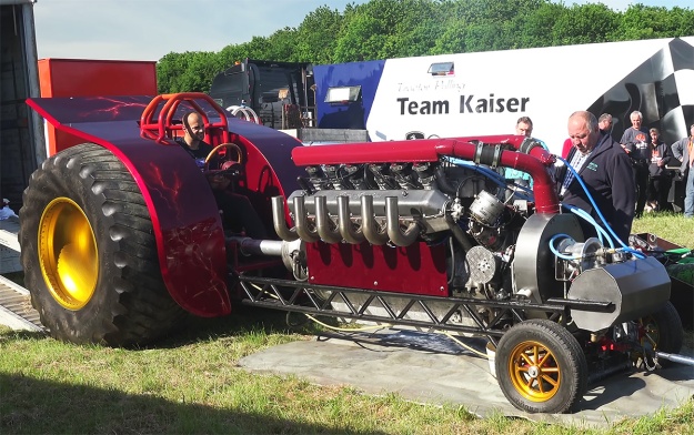
A number of Isotta Fraschini aircraft and marine engines are preserved in various museums and private collections. Some marine engines are still in operation, and the German tractor pulling group Team Twister uses a modified Isotta Fraschini W-18 engine in its Dabelju tractor.

Dabelju IF W-18 57L

The modified Isotta Fraschini W-18 in Team Twister’s Dabelju. The engine’s heads have been modified to have individual intake and exhaust ports. These crossflow heads are similar in concept to the heads used on the Macchi M.67’s engine. (screenshot of Johannes Meuleners Youtube video)

Sources:
Isotta Fraschini Aviation (undated catalog, circa 1930)
Isotta Fraschini Aviation (1929)
Isotta Fraschini Aviazione (undated catalog, circa 1931)
Istruzioni per l’uso del motore Isotta-Fraschini Tipo Asso 750 (1931)
Istruzioni per l’uso del motore Isotta-Fraschini Tipo Asso 750 R (1934)
Istruzioni per l’uso del motore Isotta-Fraschini Tipo Asso 750 RC 35 (1936)
Istruzioni per l’uso del motore Isotta-Fraschini Tipo Asso 1000 (1929)
Aeronuatica Militare Museo Storico Catalogo Motori by Oscar Marchi (1980)
Aircraft Engines of the World 1941 by Paul H. Wilkinson (1941)
Jane’s All the World’s Aircraft 1931 by C. G. Grey (1931)
https://www.t38.se/marinens-motortyper-i-mtb/
http://www.crmmotori.it/interna.asp?tema=16

cummins 1952 28 start

Cummins Diesel Indy 500 Racers

By William Pearce

Clessie Lyle Cummins was a self-taught engineer. In 1911, he served on the pit crew for Ray Harroun’s #32 Marmon Wasp racer, which won the inaugural Indianapolis 500 race. Clessie went on to start the Cummins Engine Company in 1919 and specialized in diesel engines. The Cummins company struggled in its early years. Initially, Cummins engines found success powering yachts, but the company made efforts to break into the automotive field.

cummins 1931 record dc

Clessie Cummins in Washington D.C. on tour after setting the diesel speed record at 100.755 mph (162.150 km/h) on 7 February 1931 in Daytona Beach, Florida. The car was slightly modified and entered in the 1931 Indianapolis 500 race. (Indiana Public Media image via flickr.com)

The Great Depression took its toll on Cummins and also affected auto racing. To increase race participation, Eddie Rickenbacker, then-owner of the Indianapolis Speedway and American Automobile Association Contest Board president, relaxed the racing rules to allow stock-block engines up to 366 cu in (6.0 L) in 1930. Cummins saw an opportunity to help fill the racing field and gain publicity in the Indianapolis 500 by fielding a diesel-powered racer in the 1931 race. Rickenbacker agreed to the plan and offered Cummins a provisional spot provided the racer could top 80 mph (129 km/h). However, the Cummins entry would not be entitled to any winnings, because of its guaranteed entry into the field.

Cummins contracted Augie Duesenberg to modify a Duesenberg Model A chassis and install a 4-cylinder Cummins Model U engine. The Model U was a marine engine with a 4.5 in (114 mm) bore, a 6.0 in (152 mm) stroke, and a displacement of 382 cu in (6.3 L). To make the engine conform to the displacement limit, the bore of the race engine was decreased by .125 in (3 mm), resulting in a bore of 4.375 in (111 mm). This resulted in a displacement of 361 cu in (5.9L). The engine had been modified with aluminum pistons and two intake valves but retained a single exhaust valve. The race engine produced 85 hp (63 kW) at 1,500 rpm and weighed about 1,600 lb (726 kg).

cummins 1931 8 indy

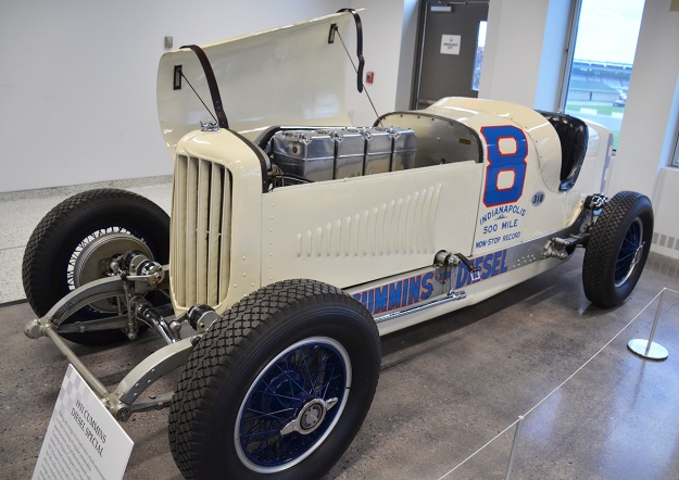
Clessie Cummins stands behind the Cummins Diesel Special #8 entered in the 1931 Indy 500. Dave Evans and Thane Houser are in the cockpit. Note the racer’s height. (IMS image)

To test the powertrain, Clessie drove the car to Daytona Beach, Florida and set a diesel flying-mile (1.6-km) speed record at 100.755 mph (162.150 km/h) on 7 February 1931. The racer was then driven to Washington D.C. and back to the Cummins factory, where it was modified in accordance with the Indy 500 rules. Its completed weight was a hefty 3,389 lb (1,537 kg).

For the Indy 500, the car was named the Cummins Diesel Special and given race #8. Dave Evans was the driver with Thane Houser as the riding mechanic / co-driver. The Cummins Diesel Special was regularly driven the 45 miles (72 km) from the Cummins factory in Columbus, Indiana to the Indianapolis Motor Speedway. The Cummins racer qualified at 96.871 mph (155.899 km/h), which was the 43rd fastest car. Since Rickenbacker had guaranteed a spot in the 40-car field, the Cummins Diesel Special was the slowest car in the 1931 Indianapolis 500. However, the Cummins team had a plan to pick up a few spots during the race.

cummins 1931 8 display

The restored #8 displayed in the Indianapolis Motors Speedway Museum. Note the engine’s four individual cylinders. (Doctorindy image via Wikimedia Commons)

On race day, 30 May 1931, the Cummins Diesel Special was driven from the factory to the raceway. The racer proved to be slow during the 500-mile (805-km) competition, but the fuel-efficient engine enabled the Cummins Diesel Special to run the entire race without stopping, the first and only racer to accomplish such a feat during the Indy 500. In those days, the race continued after the first-place car finished until each car that could finish had completed the 200 laps. The Cummins Diesel Special completed its 200th lap and finished the race 38 minutes after the race leader, which was enough to secure a 13th place finish. The diesel-powered racer averaged 86.170 mph (138.677 km/h) over the 500-mile (805-km) distance, and the amount of fuel used reportedly cost $1.40 ($23 in 2018 USD).

In 1932, Clessie Cummins and William G. Irwin (Cummins’ main financial backer) took the racer on a 5,000-mile (8,047-km) tour of Europe. This trip resulted in some modifications to the racer, such as the addition of a windshield and headlights. The Duesenberg-built Cummins Diesel Special was preserved by Cummins and restored to its Indy-race configuration. The car is often displayed in various museums and run on rare occasion at special events.

cummins 1934 6 indy

Dave Evans and Jigger Johnson in the four-stroke #6 at Indy in 1934. The Roots supercharger can just be seen at the front of the car. (IMS image)

The Cummins Team returned in 1934 to race in the Indy 500. Cummins fielded two Duesenberg-chassis cars for the race, each powered by an experimental, supercharged, aluminum, inline-four engine. The engine had a 4.875 in (124 mm) bore and stroke and displaced 364 cu in (6.0L). The difference between the cars was primarily a difference in engines, with one car using a four-stroke engine and the other car using a two-stroke engine. The Indy 500 race served as a test to compare the two different combustion cycle engines. The Roots-type supercharger was driven from the engine and installed at the front of the car. The supercharger in the four-stroke car took about 7 hp (5 kW) to run, compared with 37 hp (28 kW) for the two-stroke car, which also used the supercharger for cylinder scavenging. The four-stroke engine had one intake valve and one exhaust valve. The two-stroke engine had two exhaust valves and intake ports in the cylinder that were uncovered by the piston. Each engine produced approximately 135 hp (101 kW) at 2,500 rpm. The engines each weighed about 1,000 lb (454 kg), and each car weighed around 3,200 lb (1,451 kg).

cummins 1934 6 engine

The #6 car with the Roots supercharger passing induction air through the radiator and to the engine. (IMS image)

The four-stroke car, race #6, was driven by Dave Evans with John ‘Jigger’ Johnson as the riding mechanic. It qualified in 22nd place at 102.414 mph (164.819 km/h). During the race, #6 made its first pitstop after 200 miles (322 km). Unfortunately, engine torque damaged the transmission as the racer quickly accelerated to reenter the track. This forced Evans and Johnson to retire from the race, and #6 was awarded 19th place. The engine in #6 had operated flawlessly during the race. The car has been preserved by Cummins and is occasionally displayed for special events.

cummins 1934 6 display

The restored #6 car displayed in the Cummins Museum at the Company’s corporate headquarters in Columbus, Indiana. (Ricky Berkey image)

cummins 1934 5 daytona clessie

Clessie Cummins stands by the two-stroke #5 racer at Indy in 1934 with Stubby Stubblefield and Bert Lustig in the cockpit. The Roots supercharger can be seen through the car’s grille. The racer’s 12th place finish is the best for a diesel-powered car in the Indy 500. (Indiana Public Media image via flickr.com)

The two-stroke car, race #5, was driven by Stubby (Wilburn Hartwell) Stubblefield with Bert Lustig as the riding mechanic. The car qualified 29th at 105.921 mph (170.463 km/h). Although the two-stroke engine was temperamental, #5 went the distance and finished the 500-mile (805-km) race in 12th place, averaging 88.566 mph (142.533 km/h). Evans took over driving duties from Stubblefield around mid-race. Race #5 was the last car to complete the 200 laps—finishing the race trailing smoke and overheating. After the racer was shut down, the pistons seized in the cylinders. Some sources indicate that Clessie was so displeased with the two-stroke engine that it was tossed into a river as the team made its way back to Columbus. Because of the issues with the two-stroke engine, Cummins subsequently abandoned two-stroke development and focused on four-stroke engines.

cummins 1934 5 daytona

After Indy, a four-stroke, six-cylinder engine was installed in the #5 racer. Wild Bill Cummings set diesel speed records on Daytona Beach Florida in 1935 and is seen behind the wheel. The front of the car was stretched to accommodate the longer engine. Note the six-to-one exhaust manifold. (Cummins image)

Race #5 was later modified (lengthened) to accommodate a four-stroke, six-cylinder engine. Wild Bill Cummings used the updated #5 to set a flying-mile (1.6 km) diesel speed record of 133.023 mph (214.080 km/h) on 1 March 1935. The following day, Cummings increased the record speed to 137.195 mph (220.794 km/h). Cummings in Race #5 also set 5 km (3.1 mi) and 5 mi (8.0 km) records of 126.99 mph (204.37 km/h) and 112.07 mph (180.36 km/h) respectively. However, the event was not sanctioned, and none of these records were internationally recognized. Race #5 was preserved by Cummins in its record-setting form and is occasionally displayed in various museums.

Cummins 1934 5 Amelia Island

The restored #5 in its Daytona configuration with a four-stroke, six-cylinder engine. The car was displayed for a time at the Auburn-Cord-Duesenberg Museum on account of its Duesenberg chassis. As seen above, #5 is at the Amelia Island Concours d’Elegance in April 2019. (The Southern Concours / John E. Adams image)

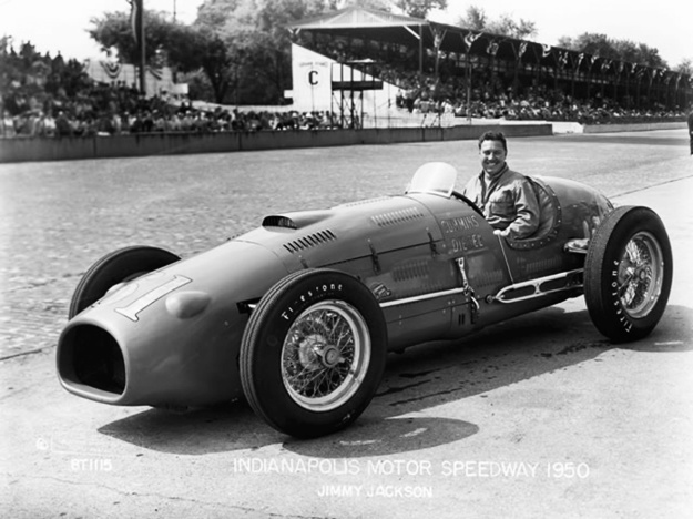
It was not until 1950 that Cummins returned to the Indy 500. The car was called the Cummins Diesel Special (just like the 1931 entry) and wore race #61. Because of its green color, driver Jimmy Jackson referred to the car as the Green Hornet. The racer consisted of a modified Kurtis Kraft chassis powered by a supercharged inline-six engine based on the Cummins JBS-600 truck engine. The car used disc brakes, which was a first at Indy.

cummins 1950 61 indy

Jimmy Jackson sits in the 1950 Cummins Diesel Special #61 at Indy. Although much more refined compared to the earlier racers, #61 was still a heavy brute compared to the rest of the field. Induction air was brought in via the front tunnel. The scoop on the engine cowling provided clearance for the cylinder head and airflow to help cool the engine, but overheating was still a problem. (IMS image)

The Roots-type supercharger was crankshaft-driven and mounted in front of the engine. The special engine had four-valves per cylinder and used an aluminum crankcase, cylinder block, and head. Two injectors delivered fuel into each cylinder, and the engine used an early design of what would become Cummins’ PT (Pressure-Timed) fuel injection. The engine had a 4.125 in (105 mm) bore and a 5.0 in (127 mm) stroke. It displaced 401 cu in (6.6 L) and produced 320 hp (239 kW) at 4,000 rpm. With the ram-air effect of the racer at speed providing additional boost, the engine’s output increased to 340 hp (254 kW) at 4,000 rpm. The engine weighed 860 lb (390 kg).

cummins 1950 61 engine

The uncowled #61 with Jackson in the cockpit. Note the crossflow head with the intake manifold on one side and the exhaust manifold on the other. The earlier Indy racers had the intake and exhaust manifolds on the same side (passenger) of the engine. The car’s independent front suspension was a first at Indy. (Motor Trend image)

Despite some difficulty, the diesel-powered Green Hornet eventually qualified for the Indy 500 at 129.208 mph (207.940 km/h), the slowest qualifying speed of the grid. During the race, the car was retired on lap 52, while in 29th place, because of issues with the engine’s vibration damper and supercharger drive. Repaired, and at the Bonneville Salt Flats on 11 September 1950, Jackson and the Green Hornet set six International diesel speed records: 163.82 mph (263.64 km/h) over 1 km (.6 mi), 165.23 mph (265.91 km/h) over 1 mile (1.6 km), 164.25 mph (264.33 km/h) over 5 km (3.1 mi), 161.92 mph (260.59 km/h) over 5 mi (8.0 km), 147.63 mph (237.59 km/h) over 10 km (6.2 mi), and 148.14 mph (238.41 km/h) over 10 mi (16 km). The previous diesel records up to 5 km (3.1 mi) were set by George Eyston and the Flying Spray in April 1936. The previous 5 km (3.1 mi) and 5 mi (8.0 km) records were those set by Wild Bill Cummings and Race #5 in March 1935. The Green Hornet was preserved by Cummins and is often displayed in various museums. On rare occasions, the car is run at special events.

cummins 1950 61 display

The 1950 racer was nicknamed Green Hornet on account of its paint. After Indy, #61 and Jackson set six diesel speed records at the Bonneville Salt Flats in Utah. The Green Hornet is pictured as displayed in the Indianapolis Motors Speedway Museum. (AutoDesign image)

In 1951, Cummins decided to make a serious attempt for the 1952 Indy 500. Clessie’s brother Don Cummins headed the team, with Nev Reiners as the chief engineer. Also on the team were Thane Houser (riding mechanic / co-driver for the 1931 Indy effort), Bill Doup, Mike Fellows, Art Eckleman, and Joe Miller. The Cummins Team worked directly with Frank Kurtis of Kurtis Kraft to design a low-slung chassis, and every opportunity was taken to exploit the chassis-engine combination.

cummins 1952 28 indy

Freddie Agabashian and crew with the 1952 Cummins Diesel Special #28 at Indy. The engine installed on its side made the car a low and sleek racer. Compare #28’s height with that of the earlier racers. (IMS image)

Powering the new racer was a further development of the JBS-600-based engine used in the Green Hornet. Since the new engine was turbocharged, it is often referred to as a modified JT-600. The engine consisted of a magnesium crankcase with an aluminum cylinder bank and head. Concepts from Cummins’ NHH-series engines (inline-six laid on its side) were applied to the race engine, and it was installed in the racer’s chassis laid over at an 85-degree angle—nearly on its side. This resulted in a very low engine cowling about 23 in (.58 m) above the ground. The turbocharger was installed in front of the engine on the right side of the car and provided up to 20 psi (1.38 bar) of boost. Like with the Green Hornet, a precursor to the Cummins’ PT fuel injection system was employed. The engine had a 4.125 in (105 mm) bore, a 5.0 in (127 mm) stroke, and a displacement of 401 cu in (6.6 L). The power produced was 380 hp (283 kW) at 4,000 rpm and 430 hp (321 kW) at 4,500 rpm. The engine weighed around 750 lb (340 kg).

The crankshaft, transmission, and driveline were on the left side of the car, putting 150 lb (68 kg) of weight bias on the left side of the car for better handling around the oval track. The cockpit was offset to the right, and the driver’s position was very low, only 4 in (102 mm) off the ground. The racer’s configuration resulted in a very low center of gravity, but the car was quite heavy at around 3,100 lb (1,406 kg). The turbocharger was a first at Indy, as was the offset drivetrain and the car’s independent front suspension. The aerodynamics of the chassis and bodywork were fine-tuned in a wind tunnel, which was reportedly another Indy first.

cummins 1952 28 no body

With the body removed, the compact nature of #28’s chassis is revealed. The turbocharger can just be seen between the front tires. On the left side of the car, note the underside of the crankcase and the driveline extending to the rear. (Cummins image)

The car was completed in late 1951, and testing began in November. Again christened as the Cummins Diesel Special, the car was given race #28 and was driven by Freddie Agabashian. Early testing indicated a very fast car, and Agabashian was careful not to reveal the racer’s full potential during practice sessions at Indy. Agabashian would not run full power for complete laps because there was some concern that the car would be banned had its true, competitive speed been reached. Fifteen minutes before the end of Pole Day qualifying, Agabashian took #28 out and set a one-lap record at 139.104 mph (223.866 km/h) and a
four-lap record at 138.010 mph (222.106 km/h). Agabashian and #28 had qualified in 1st place in a diesel. Agabashian had pushed the racer so hard that he tore the tread off some of the tires. The qualifying record was short-lived, as two cars later qualified with faster speeds, but it was still a major accomplishment for the Cummins Team.

On 30 May 1952, the Indy 500 was run. Agabashian in #28 found the diesel slower to accelerate than the other cars. Another problem cropped up with a buildup of tire rubber debris clogging the turbocharger intake. This issue ultimately caused the turbocharger to fail and forced #28 to retire on lap 71. At that point, Agabashian was in 5th place and had averaged 131.5 mph (211.6 km/h). The race was eventually won at a 130.843 mph (210.571 km/h) average, indicating #28 was keeping pace. Race #28 was credited with a 27th place finish. In short order, rules were changed, and the Cummins Diesel Special was the last diesel-engine racer to compete in the Indy 500.

cummins 1952 28 start

Agabashian and #28 set off from the pits at Indy for a practice run. Unlike racers of today, the smoke at the back of the car is diesel smoke exhaust and not tire smoke. Note the indentation ahead of the front tire. The body was so wide that body indentations were needed for full lock tire clearance. (Cummins image)

Race #28 was returned to the Cummins factory in Columbus, Indiana where it was preserved. A restoration in 1968 revealed that the crankshaft had cracked and would have failed completely had the turbocharger issues not brought a halt to #28’s race. The racer was occasionally run for special events until 1999. In 2016, the Cummins Diesel Special underwent a restoration and was run for the first time since 1999. The racer is often displayed at the Cummins Museum and run on rare occasion at special events.

In each of its four outings at Indy, Cummins took advantage of rules that enabled the displacement of diesels to be up to twice that of spark-ignition engines. While this did offer an advantage for diesels, nearly everything else about the engine was a disadvantage compared to the standard racers. Cummins used the Indy 500 to showcase its diesel engines, test new technology, and make a statement about diesel power.

cummins 1952 28 goodwood

After its 2016 restoration, #28 participated in the 2017 Goodwood Festival of Speed in Chichester, UK. Bruce Watson, a retired Cummins Engineer, is driving the racer and also led the car’s restoration. (Steve Siler / Car and Driver image)

A sponsorship agreement between Cummins and the Indianapolis Motor Speedway will provide for all five diesel Indy cars to make a parade lap before the 2019 Indy 500. The event, which coincides with Cummins’ 100-year anniversary, will be the first time that the five cars have run together.

Cummins Diesel Indy Cars 2019

All five of the Cummins Diesel Indy Cars on display in May 2019 prior to the Indy 500 race. (Cummins image)

Sources:
– “Cummins at the Brickyard” by Karl Ludvigsen, Car Life (July 1969)
– “Diesels at Speed” by Griffith Borgeson, Motor Trend (December 1950)
– “The Triumph of the Diesel” Popular Mechanics (July 1934)
http://www.trucktrend.com/cool-trucks/0808dp-cummins-diesel-race-car/
http://www.trucktrend.com/news/1605-cummins-wakes-1952-diesel-special-indy-car-after-years-of-slumber/
http://triplettracehistory.blogspot.com/2016/01/the-1931-cummins-diesel-photo-by-author.html
https://www.allpar.com/corporate/bios/cummins.html
https://stevemckelvie.wordpress.com/2011/06/05/the-cummins-diesel-special-at-the-1952-indianapolis-500/
https://www.thetruthaboutcars.com/2015/10/clessie-cummins-made-diesels-king-road-almost-indy-part-one/
https://www.thetruthaboutcars.com/2015/10/clessie-cummins-made-diesels-king-road-almost-indy-part-two/
https://www.cummins.com/company/history/indianapolis-500
https://www.caranddriver.com/features/when-cummins-diesels-assaulted-indy-feature
https://www.conceptcarz.com/vehicle/z15198/duesenberg-cummins-diesel-indy-racer.aspx
https://www.hemmings.com/blog/index.php/2011/08/02/diesels-at-daytona/
https://cumminsengines.com/No-28-cummins-diesel-special-to-run-with-moto
https://www.hotrodhotline.com/feature/heroes/landspeedracing/2009/09newsletter122/

SGP Sla 16 X-16 front

SGP Sla 16 (Porsche Type 203) X-16 Tank Engine

By William Pearce

In 1943, Simmering-Graz-Pauker (SGP) in Vienna, Austria was tasked by the Heereswaffenamt (HWA, German Army Weapons Agency) to develop a new main tank engine for the Heer (German Army). The requested engine was an air-cooled diesel that would only require minor modifications to be interchangeable with the existing engine installed in various German tanks. The existing engine was the liquid-cooled Maybach HL230 V-12 that produced 690 hp at 3,000 rpm and displaced 1,409 cu in (23.1 L). However, reliability issues with the HL230 limited the engine to 2,500 rpm and 600 hp (447 kW). The demand for an air-cooled diesel was dictated by Adolf Hitler, and SGP was to work closely with Porsche GmbH to develop the new engine.

SGP Sla 16 X-16 front

Front view of the basic Simmering-Graz-Pauker Sla 16 engine without the airbox, turbochargers, or cooling fans. The intake manifolds and some baffling can be seen in the 45-degee Vee formed by the cylinders. Note that the intake ports are on the top of the cylinders.

Led by Ferdinand Porsche, the Porsche design and consulting firm had experience with air-cooled engines and took on the brunt of the preliminary design work for the new engine. Ferdinand Porsche had been discussing tanks and diesel tank engines with Hitler since 1942. Designed by Porsche’s Paul Netzker, the new engine was an X-16 layout consisting of four banks of four cylinders. The cylinder banks were spaced 135 degrees apart on the top and bottom and 45 degrees apart on the sides. The engine was issued Porsche designation Type 203 and SGP designation Sla 16 (which will be used for the remainder of this article).

The Simmering-Graz-Pauker Sla 16 was made of a sheet steel crankcase and used a single crankshaft with four master connecting rods. Three articulating connecting rods attached to each master rod. The cylinders were comprised of a substantially finned aluminum cylinder head screwed onto a finned, steel cylinder barrel. At the front of each cylinder bank was an injection pump that fed fuel to that bank’s cylinders. The fuel injector was positioned in the cylinder head and angled toward the 135-degree side of the cylinder. At the base of each cylinder bank was a camshaft positioned on the 135-degree side. The four camshafts were driven from the rear of the engine and operated the two valves per cylinder via pushrods and rockers. The intake and exhaust ports were located on the 45-degree side of the cylinders, with the intake port on the top of the cylinder.

SGP Sla 16 X-16 section

Transverse cross section of the Sla 16 illustrates the engine’s X configuration and the drive for the cooling fans. Note the master and articulated connecting rods and the four exhaust manifolds in the left side of the drawing.

Induction air was drawn in through a large filter placed above the engine. The air then flowed through twin turbochargers located at the engine’s rear. Two separate intake manifolds branched out from each turbocharger, with one manifold supplying the upper cylinder bank and the other manifold supplying the lower cylinder bank. The exhaust from two cylinders was paired in a single manifold so that each side of the engine had four exhaust manifolds leading to the turbocharger. The turbochargers were made by Brown Boveri and spun at a maximum of 28,000 rpm. The boost from the turbochargers was conservative at 7.3 psi (.5 bar).

To cool the engine, a fan was placed above and outside each of the two upper cylinder banks. The fans extracted warm air out from between the tight, 45-degree cylinder bank sections, which were closely baffled. As a result, cool air was drawn in through the cylinders’ cooling fins and into the 45-degree Vee. Each fan was driven via a beveled gear shaft that extended from the cooling fan to the rear of the engine. Here, an enclosed drive shaft with two universal joints and beveled gears took power from the crankshaft at the extreme rear of the engine and powered the shafts that led to the fans. The cooling fans were developed by FKFS (Forschungsinstitut für Kraftfahrwesen und Fahrzeugmotoren Stuttgart or Research Institute of Automotive Engineering and Vehicle Engines Stuttgart). The fans were 20.5 in (520 mm) in diameter and operated at 2.05 times crankshaft speed. Two oil coolers flanked each engine cooling fan.

SGP Sla 16 X-16 rear

Without all of the engine’s accessories, the drive for the cooling fans can be seen protruding from the back of the Sla 16 engine. The push rod tubes and fuel injectors are visible on the far cylinder bank. The four passageways in the rear baffle are for the exhaust manifolds.

Helical gears increased the speed of the Sla 16’s output shaft to 1.5 times crankshaft speed. The speed increase was needed because of the operating speed difference between the Sla 16 and the Maybach HL230. In order to be a direct replacement, the 2,000 rpm Sla 16 needed to have an output speed multiplier to match the 3,000 rpm HL230. Since the Sla 16’s crankshaft was in the middle of the engine’s X configuration, the step-up gears also lowered the output shaft to align with the existing transmission used with the V-12 HL230.

The Sla 16 had a 14.5 to 1 compression ratio, a 5.3 in (135 mm) bore, and a 6.3 in (160 mm) stroke. The engine’s total displacement was 2,236 cu in (36.6 L). The Sla 16 was forecasted to produce 750 hp (559 kW) at 2,000 rpm. With the cooling fans, the complete engine was approximately 5.5 ft (1.68 m) long, 8.2 ft (2.50 m) wide, and 3.8 ft (1.15 m) tall. The Sla 16 weighed 4,960 lb (2,250 kg).

By late 1943, a single-cylinder 140 cu in (2.3 L) test engine had been built and designated Type 192. The Type 192 engine passed a 48-hour test run on 6 November 1943. The single cylinder engine produced 47 hp (35 kW) at 2,100 rpm, which scaled to an output of 752 hp (561 kW) for the complete 16-cylinder engine. The listed output did not take into consideration the power needed to drive the cooling fans. With favorable results from the Type 192 tests, work moved forward on the full-size Sla 16 X-16 engine.

SGP Sla 16 X-16 fans rear

Rear view of the complete Sla 16. The airbox on the top of the engine fed air into the turbochargers via a bifurcated manifold. Note the oil coolers and cooling fans. The enclosed drive shafts for the cooling fans can been seen below the turbocharger exhaust outlets.

The first Sla 16 engine was tested in late 1944 and produced 770 hp (574 kW) at 2,200 rpm without the cooling fans. It took around 95 hp (71 kW) to drive the cooling fans, which reduced the engine’s output to 685 hp (511 kW). On 10 January 1945, two Sla 16 test engines had completed a combined 300 hours of test operation. Porsche’s involvement with the engine had essentially stopped by this time. Plans were made for Sla 16 production to start in June 1945 at the Steyr-Daimler-Puch factory in Austria. Steyr-Daimler-Puch was producing Daimler-Benz DB 603 engines (although the factory built DB 605s from October 1942 to October 1943), and production of the DB 603 would give way for the Sla 16. Some changes were incorporated into the Sla 16 production engines, such as the use of two fuel injection pumps rather than the four pumps used on the prototype engines. It is possible that the production engines carried the Porsche Type 220 designation. However, the Sla 16 engine never entered production because of the German surrender in May 1945.

A Sla 16 engine was reportedly installed in the chassis of the experimental Panzerjäger Tiger Ausf. B (Tank Hunter Tiger Variant B or Jagdtiger, Hunting Tiger) and underwent some feasibility tests. Initially, the lower cylinder banks ran hot, but modifications to the cooling fans and air baffles resolved the issue. In addition, a Panzerkampfwagen Tiger Ausf. B (Armored Fighting Vehicle Tiger Variant B), or Tiger II, was modified to accept a Sla 16 engine and waited for the engine’s installation. However, the installation was never completed. The engine was also proposed for the VK 45.02 P2 (Porsche Type 181C), which was never built. The majority of Sla 16 parts, tooling, and equipment were captured by the Soviet Union at the end of World War II.

SGP Sla 16 X-16 stand

The left image (engine inverted) shows the camshaft drives at the rear of the engine. In the center image (engine upright), the engine’s output can be seen below the crankshaft. The right image (engine almost inverted) displays the cylinder’s valves. The exhaust ports on the side of the cylinders are easily seen, while the intake ports on the top of the cylinders have been covered.

In late 1943, FKFS contemplated using the 140 cu in (2.3 L) cylinder from the Sla 16 as the starting point for a new tank engine to power the proposed Panzerkampfwagen Panther II. The FKFS engine consisted of two V-12 engines mounted 90-degrees apart on a common crankcase. The 24-cylinder engine would have displaced 3,354 cu in (55.0 L) and produced 1,100 hp (820 kW). Four engine-driven, FKFS cooling fans would have been installed, with two above each V-12 engine section. The FKFS 24-cylinder engine project did not progress beyond the drawing board, and the Panther II was never built.

A larger version of the X-16 engine was investigated under the Porsche Type 212 designation. This engine had a 5.9 in (150 mm) bore and a 6.7 in (170 mm) stroke. Total displacement of the Type 212 was 2,933 cu in (48 L), and the engine was forecasted to produce 1,500 hp (1,119 kW) at 2,500 rpm. A 183 cu in (3.0 L), single-cylinder test engine was evaluated as the Type 213, but it does not appear that the tests were completed or that a complete Type 212 engine was built. The Type 212 was proposed to power the Panzerkampfwagen VIII Maus (Porsche Type 205), but the engine was rejected by Albert Speer, the Minister of Armaments.

SGP Sla 16 X-16 test

The Sla 16 engine under test in late 1944 without cooling fans or turbochargers. However, the test equipment most likely provided forced induction.

Notes: Sources are split on the Porsche Type designation for the 750 hp (559 kW) Sla 16. Many refer to the engine as the Type 203, and just as many use Type 212. In addition, Type 180, 181, 192, and 220 are also used. Type 180 was a tank design (VK 45.02 P) that originally used Porsche’s Type 101 V-10 engine. Type 181 was the same tank reengined with the Sla 16 after the V-10 encountered problems. As mentioned in the article, Type 192 was a single-cylinder test engine for the Sla 16. Since Type 213 was a single-cylinder test engine for the larger X-16, it makes sense for the larger X-16 to be Type 212. This leaves Type 203 as the logical choice for the Sla 16. As stated in the article, Type 220 may have been the production version of the Sla 16.

Furthermore, a number of sources list the larger, 1,500 hp (1,119 kW) engine as an X-18. However, there can be no X-18 engine; to add up to a total of 18 cylinders, two banks would need to have five cylinders each, and two banks would need to have four cylinders each. Such an armament would be ill-advised. Most likely, “X-16” was either mistyped or misread as “X-18” on some scarce document captured at the end of World War II, and the misnomer stuck. However.

Lastly, the Porsche Type 181B (VK 45.02 P2) tank design was to be powered by two 16-cylinder engines. The 16-cylinder engine was an air-cooled diesel that produced 370 hp (276 kW) at 2,000 rpm. Reportedly, the design of this engine was a collaboration with Deutz. Some sources indicate the engine was a V-16, while others state it was an X-16. It is not clear whether the smaller 16-cylinder engine had anything in common with the Sla 16 or what its Type number was. The small 16-cylinder engine had a 4.3 in (110 mm) bore, a 5.1 in (130 mm) stroke, and a total displacement of 1,206 cu in (19.8 L). The small 16-cylinder engine was never built.

SGP Sla 16 X-16 general arrangement rear

General arrangement drawing of the Sla 16 engine.

Sources:
Professor Porsche’s Wars by Karl Ludvigsen (2014)
Der Panzer-Kampfwagen Tiger und seine Abarten by Walter J. Spielberger (1998)
AFV Weapons Profile: Elefant and Maus (+ E-100) by Walter J. Spielberger and John Milsom (October 1973)
Wunibald I. E. Kamm – Wegbereiter der modernen Kraftfahrtechnik by Jurgen Potthoff and Ingobert C. Schmid (2012)
Daimler-Benz in the Third Reich by Neil Gregor (1998)
https://vk.com/page-39215368_53036748
http://ftr.wot-news.com/2014/11/25/maus-engine-by-captiannemo/
http://www.alanhamby.com/maybach.shtml

MAN 6-cyl WWI

MAN Double-Acting Diesel Marine Engines

By William Pearce

Maschinenfabrik Augsburg-Nürnberg (MAN) was involved with diesel engines since their inception. From 1893 to 1897, MAN* worked with Rudolf Diesel to develop his combustion cycle and build the first diesel engines. When Diesel’s engine first ran in 1894, it produced around 3 hp (2 kW) at 88 rpm. Just 15 years later, MAN was contracted to develop a diesel engine capable of 12,000 hp (8,948 kW) at 120 rpm.

MAN 6-cyl WWI

The MAN six-cylinder, double-acting, two-stroke, 12,000 hp, diesel marine engine under construction. The three workers provide a good reference as to the engine’s size.

The remarkable rise of diesel power caught the eye of many militaries. Anton von Rieppel, general manager of MAN at Nürnberg (Nuremberg), felt that diesels had matured enough to power the latest battleships. In August 1909, Rieppel proposed a new engine to the Reichsmarine (Germany Navy). By late 1909, a development contract was issued to MAN for the construction of a 12,000 hp (8,948 kW), six-cylinder diesel engine. Six of the engines would be needed to produce the 70,000 hp (52,199 kW) required for the latest German battleships. Given the uncharted territory MAN was traversing, a three-cylinder engine would be built first to prove that a six-cylinder engine could meet the desired specifications. Other companies were also contracted to build competing engines.

MAN’s design was an inline, two-stroke engine that used double-acting cylinders. Each of the closed cylinders had a combustion chamber at its top and bottom. Originally, each combustion chamber had four intake valves, four fuel valves, and two safety valves that were also used for air-starting the engine. The safety valves were located at the center of the combustion chamber. The locations of the remaining valves were split between passageways that branched off from either side of the upper combustion chamber. With the exception of the safety valves, the valves for each side of each combustion chamber were actuated by a single underhead camshaft. This configuration had a total of 20 valves for each cylinder and four camshafts for the engine. The final (seventh) combustion chamber design retained the four intake valves but had only two fuel valves and one safety valve (located in the upper combustion chamber). The changes lowered the number of valves per cylinder to 15. Exhaust ports were located in the middle of the cylinder and were covered and uncovered by the piston.

MAN 6-cyl section

A drawing of the final cylinder design of the World War I engine. Fuel valves are on the left of the drawing, and intake valves are on the right. The exhaust manifold is positioned at the center of the cylinder. Note how the two piston halves are bolted together.

The double-headed piston was constructed of two parts. The lower part was connected to a non-articulating piston rod, and the upper part of the piston was bolted to the lower part. The piston rod was connected to the connecting rod via a cross head. The cross head slid in vertical channels on both sides of the inner crankcase. Oil was circulated through the piston to cool it. The oil flowed up through passageways in the piston rod and into the lower part of the piston. The oil then flowed to the upper part of the piston and down the center of the piston rod. The upper and lower combustion chamber sections were bolted to the center section of the cylinder, and the assembly was attached to the crankcase. A water jacket surrounded the cylinder. The center section of the cylinder and of the upper combustion chamber were made of cast iron. The crankcase, piston, lower combustion chamber, and many other components were made of cast steel. Each complete cylinder assembly was around 12 ft (3.5 m) tall, and the engine was over 24 ft 3 in (7.4 m) tall.

Each cylinder had a 33.4 in (850 mm) bore and a 41.3 in (1,050 mm) stroke. Since the piston was double-acting and there was a lower combustion chamber, each cylinder’s displacement was nearly doubled, as if it were two conventional cylinders. The upper combustion chamber displaced 36,359 cu in (595.8 L). However, the connecting rod passing through the lower combustion chamber took up around 3,021 cu in (49.5 L) of volume. Displacement for the lower combustion chamber was approximately 33,337 cu in (546.3 L). The cylinder’s total displacement was around 69,697 cu in (1,142 L). The three-cylinder test engine displaced 209,094 cu in (3,426 L), and the six-cylinder engine displaced 418,187 cu in (6,853 L). The engine drove three double-acting air pumps to scavenge the engine. Each air pump had a 52.0 in (1,320 mm) bore and a 31.5 in (800 mm) stroke.

The three-cylinder engine was first run on 12 March 1911. Severe delays occurred as technological issues were encountered. In January 1912, a failure caused the intake manifolds to explode, killing ten workers. By June 1913, the three-cylinder engine had met its requirement by producing 5,400 hp (4,027 kW) at 90% power. Construction of a six-cylinder engine followed.

The six-cylinder engine was first run on 23 February 1914. By September 1914, the engine was producing 10,000 hp (7,457 kW) at 130 rpm. By this time, World War I was underway; priorities shifted, and shortages were encountered. A single cylinder made a five-day run at over 2,000 hp (1,491 kW) in April 1915. On 24 March 1917, the six-cylinder engine produced 12,200 hp (9,098 kW) at 135 rpm for 12 hours. In April 1917, the engine passed its five-day acceptance test, running at 90% power and producing 10,800 hp (8,054 kW) at 130 rpm.

MAN M9Z 42-58

One of the MAN M9Z 42/58 engines built for installation in a Deutschland-class cruiser. At least 24 of the engines were made. The fuel injection pumps for each cylinder can be seen above and below the housing along the engine’s side.

By mid-1917, it was obvious that due to delays and the war, the engine would never be used, and the other five engines would never be built. MAN decided to test the engine to its limits. The engine test stand at MAN could not absorb the maximum anticipated power of the complete six-cylinder engine, so just one cylinder was run. On 16 October 1917, a single cylinder produced 3,570 hp (2,662 kW) at 145 rpm. If all six cylinders could match that performance, the complete engine would produce 21,420 hp (15,973 kW). The engine was later scrapped as a result of the Treaty of Versailles.

After World War I, Germany entered a period of economic ruin. It was not until 1926 that MAN designed the first engine in a new series of double-acting, two-stroke diesels. Overseen by engineer Gustav Pielstick, the new engines were similar in concept to the double-acting engine built during World War I, but they incorporated many new features. Pielstick had developed MAN submarine engines during World War I but did not work on the large double-acting engine.

MAN MZ42-58

Sectional drawings of a MAN M9Z 42/58 engine. The rotary exhaust valves are positioned in a runner between the cylinder and the exhaust manifold. Note the long through bolts that pass through the entire engine.

The main structure of the new engines was made of steel plates welded together. This construction kept the engine rigid, but made it lighter than using cast components. Pairs of very long through bolts were positioned between the cylinders. They held the center part of the cylinder, crankcase, and crankshaft together and allowed for the disassembly of individual cylinders without compromising the integrity of the overall engine. The double-headed pistons were again made in two parts. From the top, the piston rod passed through the lower part of the piston, which was threaded to a shoulder on the rod. The upper part of the piston was threaded to the top of the piston rod. The skirt of the upper part of the piston slid into the skirt of the lower part. A sealed gap between the skirts allowed for the differential expansion of the individual piston halves. The piston was oil-cooled, like the World War I engine. The lower part of the piston rod was threaded into the cross head. Unlike the World War I engine, the cross head of the new series slid in a mount attached only to one side of the crankcase.

The new engine had no valves in the cylinder. In the middle of the cylinder were two rows of intake ports. The top row serviced the upper combustion chamber, and the bottom row serviced the lower combustion chamber. Air was forced into the cylinder by an auxiliary “pumping” engine. Fuel entered the cylinder via a single injector in the upper combustion chamber and two injectors on each side of the piston rod in the lower combustion chamber. The injectors were water-cooled and provided fuel to each cylinder at 3,625–4,350 psi (250–300 bar). Mounted to the side of the engine was a camshaft that drove the fuel injection pumps. Each cylinder had an upper and lower injection pump that respectively provided fuel to the upper and lower combustion chambers. Both pumps for each cylinder were controlled by a single lobe on the camshaft.

MAN LZ 19-30 section

Sectional view of the MAN L11Z 19/30 shows that the rotary exhaust valves have been placed inside of the exhaust manifold to conserve space. Otherwise, the engine and cylinder are very similar to the larger engines.

Each combustion chamber had its own exhaust ports which led to separate manifolds for the upper and lower combustion chambers. The intake and exhaust ports were on the same side of each cylinder, and their relative positions allowed the cylinder to be loop scavenged. Rotary valves inside of the exhaust manifolds closed off the exhaust port before the piston and allowed the cylinder to be charged with incoming air. The valve itself was supported by a hollow tube through which water was circulated to keep the valve cool. Otherwise, the intake and exhaust ports were covered and uncovered by the piston. All the engines of the new series used the same basic cylinder design, but the engines differed in their bore, stroke, and number of cylinders.

After cylinder testing, the first complete engine built of this type was the D4Z 23/34. In MAN nomenclature, “4” represents the number of cylinders per bank and “23/34” the bore/stroke in cm. With its 9.1 in (230 mm) bore and 13.4 in (340 mm) stroke in a double-acting cylinder, the engine displaced around 6,591 cu in (108 L). The D4Z 23/34 produced 1,000 hp (746 kW) at 800 rpm. The D4Z 23/34 was run in 1927, and tests went well.

On 27 March 1928, the Reichsmarine contracted MAN to develop a larger engine for what would become the cruiser Leipzig. Four M7Z 30/34 engines powered the middle shaft in the Leipzig, while two other shafts were powered by steam turbines. The seven-cylinder M7Z 30/34 engine had a 11.8 in (300 mm) bore and a 13.4 in (340 mm) stroke. Each engine displaced around 19,624 cu in (321.6 L) and produced 3,100 hp (2,312 kW) at 800 rpm, giving a total of 12,400 hp (9,247 kW) for the four engines.

Compared to a steam turbine, the diesel engine took up less space, was simpler to operate, had nearly instant power, and could suffer damage without disastrous consequences. Shrapnel passing through a diesel engine would shut down the engine, most likely one of several. Shrapnel passing through a steam boiler would cause the boiler to explode, most likely killing some of the crew in the room.

MAN LZ 19-30

Front view of the MAN L11Z 19/30. The camshaft ran to the side of the cylinders and controlled the fuel injection pumps. The handle on the front of the camshaft was used to adjust the camshaft when the engine was run in reverse. (Hermann Historica image)

The Reichsmarine decided to use only diesel-power for the Deutschland-class Panzerschiffe (armored ships) cruisers: Deutschland (later renamed Lützow), Admiral Scheer, and Admiral Graf Spee. In these ships, four nine-cylinder engines powered each of two propeller shafts. Engines were ordered in October 1928 for the Deutschland, on 9 January 1930 for the Admiral Scheer, and on 14 March 1931 for the Admiral Graf Spee. The engine type for these ships was the M9Z 42/58. With a 16.5 in (420 mm) bore and a 22.8 in (580 mm) stroke, the nine-cylinder, double-acting engine displaced 84,359 cu in (1,382 L). Each engine produced 7,100 hp (2,494 kW) at 450 rpm and weighed around 110 tons (100 tonnes). Combined, the eight engines provided a total of 56,800 hp (42,356 kW).

The artillery training ship (Artillerieschulschiff) Bremse was ordered in 1931. Powering the ship were eight M8Z 30/44 engines—four engines on each of the two propeller shafts. The M8Z 30/44 was the same engine used in the Leipzig but with an additional cylinder. The eight-cylinder M8Z 30/44 engine had a 11.8 in (300 mm) bore and a 13.4 in (340 mm) stroke. It displaced 22,427 cu in (367.5 L) and produced 3,350 hp (2,498 kW) at 600 rpm, giving a total of 26,800 hp (19,985 kW) for the eight engines.

The light cruiser Nürnberg was ordered in 1933 and used a combination of diesel engines and steam turbines, like its sister ship, the Leipzig. Four M7Z 32/44 engines powered the ship’s center shaft. The engines were larger than the ones used on the Leipzig but appear to have the same rated output. The M7Z 32/44 engine had a 12.6 in (320 mm) bore and a 17.3 in (440 mm) stroke. The seven-cylinder engine displaced 28,894 cu in (473 L) and produced around 3,100 hp (2,312 kW) at 600 rpm, giving a total of 12,400 hp (9,247 kW) for the four engines.

MAN piston rods

The piston, piston rod, connecting rod, and crankshaft section for a M9Z 65/95. The piston halves were threaded onto the piston rod, which was threaded to the cross head. An oil line can be seen attached to the cross head. The assembly is displayed in the Deutsches Museum in Munich. (enwo image)

Around 1933, the Reichsmarine looked to steam turbines to fulfill their power needs, so the funding for MAN’s large diesel marine engines was severely cut. At the same time, a new engine was needed to power the latest German airships, the LZ 129 Hindenburg and LZ 130 Graf Zeppelin II. Pielstick adapted the basic design of the double-acting diesel to create a lighter, smaller engine, the L7Z 19/30. After the Daimler-Benz DB 602 engine was selected to power the airships, MAN added four cylinders to the L7Z engine to create the 11-cylinder L11Z 19/30 for marine use. The L11Z 19/30 used an engine-driven blower to provide intake air and cylinder scavenging. The engine had a 7.48 in (190 mm) bore, a 11.81 in (300 mm) stroke, and a total displacement of around 10,979 cu in (179.9 L). The L11Z 19/30 had a maximum output of 2,000 hp (1,491 kW) at 1,050 rpm and a continuous output of 1,400 hp (1,044 kW) at 900 rpm. The engine was approximately 157 in (4.0 m) long, 39 in (1.0 m) wide, and 98 in (2.5 m) tall. It weighed around 8,378 lb (3,800 kg) and was reversible. L11Z 19/30 engines were used in torpedo boats, with three engines installed in each Schnellboot S 14 to S 17 (S 14 was launched in January 1936) and four engines installed in the Versuchs Schnellboot VS 5 (launched in January 1941). The three L11Z 19/30 engines from S 15 survived. One engine is in the MAN Museum in Augsburg; one is in the Deutsches Museum in Munich, and one is in a private collection.

In 1935 and under Nazi leadership, the Reichsmarine was renamed Kriegsmarine. That same year, the Kriegsmarine initiated the design of new H-class battleships. The first of the ships would be powered by diesel engines. In 1938, the Kriegsmarine showed a renewed interest in large diesel marine engines, and MAN’s developmental funding was substantially increased. MAN developed the M9Z 65/95 engine for the H-class battleships in 1938. Four of these engines would power each of three shafts. The nine-cylinder engine had a 25.6 in (650 mm) bore, a 37.4 in (950 mm) stroke, and a total displacement of approximately 330,945 cu in (5,423 L). The M9Z 65/95 weighed around 248 tons (225 tonnes) and had a continuous output of 12,500 hp (9,321 kW) at 256 rpm and an emergency output of 13,750 hp (10,253 kW) at 265 rpm. The 12 engines gave a total of 150,000 hp (111,855 kW) for continuous operation and 165,000 hp (123,040 kW) for emergencies. In early 1939, 24 M9Z 65/95 engines were ordered by the Kriegsmarine, followed later in the year by another order for 24 engines. However, the orders were cancelled in late 1939, and only one test engine was built. This engine was tested in 1940 but was destroyed during an Allied air raid. A piston and rod assembly survived and is displayed in the Deutsches Museum in Munich. No H-class battleships were completed.

MAN V12Z 32-44 section

Sectional view of the MAN V12Z 32/44 engine illustrates a cylinder design similar to that used on the inline engines but with a completely different manifold arrangement. The large upper manifold was the intake, and the three other manifolds were for exhaust. Note the camshaft and fuel injection pumps on the outside of the cylinder banks.

By 1939, Pielstick used the basic cylinder design of previous engines to create larger and more powerful engines in a V configuration with 24 cylinders. The V-24 engines had a 45 degree bank angle and a new manifold arrangement, but the cylinder design and other components were similar to the previous inline engines. Positioned in the Vee of the engine was a lower exhaust manifold that collected the exhaust gases from the lower combustion chambers. Above this manifold was the intake manifold that serviced all the cylinders. Each cylinder bank had an upper exhaust manifold that collected the exhaust gases from the upper combustion chambers. These manifolds were positioned between the intake manifold and the respective cylinder bank. The fuel injection camshaft and pumps were located on the outer side of the cylinder banks. An engine-driven blower was positioned at the rear of the engine and fed air into the intake manifold.

The first V-24 was designated V12Z 42/58, and the engine was designed for the German O-class battlecruisers, with four engines powering each of two shafts. A third shaft was powered by a steam turbine. The V12Z 42/58 had a 16.5 in (420 mm) bore, a 22.8 in (580 mm) stroke, and displaced around 224,957 cu in (3,686 L). The 150.5-ton (136.5-tonne) engine produced 15,600 hp (11,633) at 450 rpm. The eight engines planned for use in the O-class would have produced a total of 124,800 hp (93,063 kW), but the O-class was cancelled, and no ships were built. One V12Z 42/58 engine was built and completed a 200-hour test run, generating a continuous 10,000 hp (7,457 kW) at 243 rpm.

A second, smaller V-24 engine was the V12Z 32/44 (sometimes called the V24Z 32/44). This engine was designed in 1940 for the Zerstörer 1942, of which one was built, the Z 51. Most sources state that the Z 51 was powered by six engines, with two engines powering each of three shafts. Other sources claim the center shaft had four engines and that the outer shafts had one engine each. The V12Z 32/44 had a 12.6 in (320 mm) bore and a 17.3 in (440 mm) stroke. The engine displaced around 99,066 cu in (1,623 L) and produced 10,000 hp (7,457 kW) at 600 rpm. A turbocharged version was planned that would increase output to 16,000 hp (11,931 kW). The V12Z 32/44 weighed 56.0 tons (50.8 tonnes), and the turbocharged version weighed 66 tons (60 tonnes). The Z 51 destroyer was nearly complete when it was sunk during an allied attack on 21 March 1945. Sources state that either four or six V12Z 32/44 engines were built. One engine was preserved and is on display in the Auto & Technik Museum in Sinsheim.

MAN V12Z 32-44 construction

The MAN V12Z 32/44 engine under construction. The blower was mounted to the rear of the engine. Note the many access panels incorporated into the engine’s crankcase.

In the early 1950s, MAN again offered their double-acting, two-stroke diesel engines. The largest of these post-war engines was the D8Z 70/120. With a 27.6 in (700 mm) bore and a 47.2 in (1,200 mm) stroke, the eight-cylinder engine displaced 430,953 cu in (7,062 L) and produced 8,000 hp (5,966 kW) at 120 rpm. More efficient engines that required less maintenance overtook the double-acting, two-stroke power plants. Today, MAN continues to build diesels for automotive, industrial, and marine use.

*Maschinenfabrik Augsburg AG worked with Rudolf Diesel. The company merged with Maschinenbau-AG Nürnberg in 1898 to become Vereinigten Maschinenfabrik Augsburg und Maschinenbaugesellschaft Nürnberg (United Machine Factory Augsburg and Machinery Construction Company Nuremberg). In 1908, the company was renamed Maschinenfabrik Augsburg-Nürnberg (MAN).

MAN V12Z 32-44

The 24-cylinder MAN V12Z 32/44 engine as displayed in the Auto & Technik Museum in Sinsheim. The cars behind the engine give an indication of the engine’s size. Note the large blower housing attached to the engine. Six of these engines were to power the Z 51 destroyer. (Technik Museum Sinsheim und Speyer image)

Sources:
– “Multicylinder Combustion Engine” US patent 1,836,498 by Gustav Pielstick (granted 15 December 1931)
– “Internal Combustion Engine” US patent 1,887,661 by Gustav Pielstick (granted 15 November 1932)
– “Fuel Valve” US patent 1,919,904 by Gustav Pielstick (granted 25 July 1933)
– “Piston for Double Acting Internal Combustion Engines” US patent 1,922,393 by Gustav Pielstick (granted 15 August 1933)
– “Internal Combustion Engine” US patent 1,962,523 by Gustav Pielstick (granted 12 June 1934)
– “Housing for a Vertical Combustion Power Engine” US patent 1,969,031 by Gustav Pielstick (granted 7 August 1934)
Diesel’s Engine by Lyle Cummins (1993)
Ungewöhnliche Motoren by Stefan Zima and Reinhold Ficht (2010)
Pocket Battleships of the Deutschland Class by Gerhard Koop and Klaus-Peter Schmolke (2014)
http://www.deutsches-museum.de/en/collections/machines/power-engines/combustion-engines/diesel-engines/large-diesel-engines/marine-diesel-engine-1938/
http://www.deutsches-museum.de/en/collections/machines/power-engines/combustion-engines/diesel-engines/large-diesel-engines/marine-engine-l11z-1930-1939/
http://www.hermann-historica-archiv.de/auktion/hhm61.pl?f=NR_LOT&c=6902&t=temartic_M_GB&db=kat61_m.txt

mercedes-benz-mb-518-v-20-rear

Mercedes-Benz 500 Series Diesel Marine Engines

By William Pearce

Daimler-Benz was formed in 1926 with the merger of Daimler Motoren Gesellschaft and Benz & Cie. Prior to their merger, both companies produced aircraft engines under the respective names Mercedes and Benz. After the merger, the Daimler-Benz name was used mostly for aircraft engines, and the Mercedes-Benz name was used mostly for automobile production. However, both names were regularly applied to marine engines. For clarity in this article, the name Daimler-Benz will refer to aircraft engines, and the name Mercedes-Benz will refer to marine engines.

mercedes-benz-mb-501-v-20-rear

The MB 501 shows the close family resemblance to the DB 602, but the engines had Vees of different angles and completely different valve trains. The tubes for the pushrods can be seen on the outer side of the cylinders. Note the two water pumps on the rear sides of the engine.

As Germany began its rearmament campaign in the 1930s, high-performance marine diesel engines were needed to power various motorboats. The Kriegsmarine (German Navy) turned to Mercedes-Benz to supply a series of high-speed diesel engines. These engines were part of the MB 500 series of engines that were based on the Daimler-Benz DB 602 (LOF-2) engine developed to power the LZ 129 Hindenburg and LZ 130 Graf Zeppelin II airships. The 500 series diesel engines were four-stroke, water-cooled, and utilized a “V” cylinder arrangement.

The first engine in the 500 series was the MB 500 V-12. The engine’s two cylinder banks were separated by 60 degrees. The MB 500 used individual steel cylinders that were attached to an aluminum alloy crankcase. About a third of the cylinder was above the crankcase, and the remaining two-thirds protruded into the crankcase. This arrangement helped eliminate lateral movement of the cylinders and decreased vibrations. The crankcase was made of two pieces and split horizontally through the crankshaft plane. The lower part of the crankcase was finned to increase its rigidity and help cool the engine oil.

mercedes-benz-mb-501-v-20-crackington

The crankcases of the wrecked MB 501 engines on Crackington Haven Beach have completely dissolved over the years from constant exposure to salt water. Only the engine’s steel components remain. Note the fork-and-blade connecting rods. The engine’s gear reduction can be seen on the left side of the image. (gsexr image via 350z-uk.com)

Each cylinder had two intake and two exhaust valves. The camshaft had two sets of intake and exhaust lobes per cylinder. One set was for normal operation, and the other set was for running the engine in reverse. The fore and aft movement of the camshaft to engage and disengage reverse operation was pneumatically controlled. Bosch fuel injection pumps were located at the rear of the engine and were geared to the camshaft. Each injection pump provided fuel to the cylinders at 1,600 psi (110.3 bar). Fuel was injected into the center of the pre-combustion chamber, which was in the center of the cylinder head and between the four valves. For low-speed operation, fuel was cut from one bank of cylinders.

The MB 500 had a compression ratio of 16.0 to 1. The engine used fork-and-blade connecting rods that rode on roller bearings fitted to the crankshaft. The camshaft also used roller bearings, but the crankshaft was supported by plain bearings. Speed reduction of the engine’s output shaft was achieved through the use of bevel planetary gears. Two water pumps mounted to the rear sides of the engine circulated water through the cylinder banks. Each pump provided cooling water to one cylinder bank. The pumps were driven by a cross shaft at the rear of the engine. The engine was started with compressed air.

mercedes-benz-mb-502-v-16

With the exception of the different intake manifolds, the MB 502 was nearly identical to the DB 602. Note the Mercedes-Benz emblem on the rear of the V-16 engine.

The MB 500 had a 6.89 in (175 mm) bore and a 9.06 in (230 mm) stroke. This cylinder size directly corresponded to the cylinder size used on the DB 602. The MB 500’s displacement was 4,051 cu in (66.39 L). The engine had a continuous output of 700 hp (522 kW) at 1,460 rpm and a maximum output of 950 hp (708 kW) at 1,630 rpm. Fuel consumption was .397 lb/hp/hr (241 g/kW/hr). The MB 500 was 9.6 ft (2.93 m) long, 3.2 ft (.98 m) wide, and 5.7 ft (1.73 m) tall. The engine weighed around 4,784 lb (2,170 kg). MB 500 engines were installed in Schnellboote that Germany built for Bulgaria. A Schnellboot, or S-boot, was a fast attack boat and was referred to as an E-boat (Enemy boat) by the Allies.

For more power, the MB 501 was built with two rows of ten cylinders, creating a V-20 engine. The MB 501 was similar to the MB 500, but it also had a number of differences. A 40 degree angle separated the cylinder banks, and a second set of fuel injection pumps was driven from the front of the engine. The MB 501 used two camshafts positioned in the upper crankcase, one on each side of the engine. Rollers on the lower end of the pushrods rode on the camshaft. Two pushrods for each cylinder extended up along the outer side of the cylinder bank to operate a set of duplex rocker arms for the two intake and two exhaust valves. The fork-and-blade connecting rods were attached to the crankshaft with plain bearings.

mercedes-benz-mb-507-v-12

The MB 507 was based on the DB 603 inverted V-12 aircraft engine. Although the engine’s architecture was similar, the MB 507 had a completely different crankcase and reduction gear than the DB 603, and it was not supercharged.

The MB 501’s bore and stroke were increased over the MB 500’s to 7.28 in (185 mm) and 9.84 in (250 mm) respectively. The engine displaced 8,202 cu in (134.40 L). The MB 501 had a continuous output of 1,500 hp (1,119 kW) at 1,480 rpm and a maximum output of 2,000 hp (1,491 kW) at 1,630 rpm. Fuel consumption was .397 lb/hp/hr (241 g/kW/hr). The engine was 12.7 ft (3.88 m) long, 5.2 ft (1.58 m) wide, 5.6 ft (1.71 m) tall, and had a weight of 9,303 lb (4,220 kg). Three MB 501 engines were installed in each 1937 class Schnellboot. Six engines were installed in each of the U-180 and U-190 submarines. However, the MB 501 engines proved unsuitable in the submarines, and they were soon replaced by MAN diesels. The remains of three MB 501 engines can be found on Crackington Haven Beach in southeast Britain. The engines belonged to Schnellboot S-89, which was surrendered to the British after World War II. S-89 slipped its tow on 5 October 1946 and was wrecked upon the shore.

The MB 502 was essentially a Daimler-Benz DB 602, except it had water jacketed intake manifolds that protruded above the engine’s Vee. The rest of the MB 502’s specifics mirrored those of the DB 602. The MB 502 was a 50 degree V-16 with a single camshaft located in the Vee of the engine. The engine had a 6.89 in (175 mm) bore and a 9.06 in (230 mm) stroke. The MB 502 displaced 5,401 cu in (88.51 L) and had a continuous output of 900 hp (671 kW) at 1,500 rpm and a maximum output of 1,320 hp (984 kW) at 1,650 rpm. The engine was 9.9 ft (3.02 m) long, 4.0 ft (1.22 m) wide, and 6.2 ft (1.90 m) tall. The MB 502 weighed 5,952 lb (2,700 kg) and had a fuel consumption at cruising power of 0.37 lb/hp/hr (225 g/kW/hr). Three MB 502 engines were installed in each 1939 class Schnellboot.

mercedes-benz-mb-511-v-20-aeronauticum

The MB 511 engine on display in the Aeronauticum museum in Germany. Note the finning on the lower half of the crankcase. On the front of the engine (left side of image) is the gear reduction with the supercharger above. The square connection above the engine is for the induction pipe. (Teta pk image via Wikimedia Commons)

The MB 507 was based on the Daimler-Benz DB 603 inverted V-12 aircraft engine, but some features from the DB 602 were incorporated. The normally aspirated MB 507 was an upright V-12 diesel engine that used monobloc cylinders and had a compression ratio of 17 to 1. A new finned crankcase was fitted that was similar to those used on other MB 500 series diesel engines. For the initial MB 507 engines, the bore was decreased from the 6.38 in (162 mm) used on the DB 603 to 6.22 in (158 mm). The stroke was unchanged at 7.09 in (180 mm). This gave the MB 507 a displacement of 2,584 cu in (42.35 L). The DB507 weighed 1,834 lb (850 kg). The engine had a continuous output of 700 hp (522 kW) and a maximum output of 850 hp (634 kW) at 2,300 rpm. An updated version of the engine, the MB 507 C, reverted back to the 6.38 in (162 mm) bore, which increased its displacement to 2,717 cu in (44.52 L). The MB 507 C produced 750 hp at 1,950 rpm and 1,000 hp at 2,400 rpm. The engine was 6.0 ft (1.83 m) long, 2.6 ft (.79 m) wide, 3.5 ft (1.06 m) tall, and had a weight of 1,742 lb (790 kg). Two MB 507 engines were used in a few LS boats (Leicht Schnellboot or Light Fast boat), and the engine was also installed in some land vehicles, such as the Karl-Gerät self-propelled mortar.

The MB 511 was a supercharged version of the MB 501 V-20 engine. The bore, stroke, and displacement were unchanged, but the compression ratio was decreased to 14 to 1. The supercharger was positioned at the front of the engine, above the gear reduction. With the supercharger, output increased to 1,875 hp (1,398 kW) at 1,480 rpm for continuous power and 2,500 hp (1,864 kW) at 1,630 rpm for maximum power. The MB 511 was 13.1 ft (4.00 m) long, 5.2 ft (1.58 m) wide, and 7.6 ft (2.33 m) tall. The engine weighed 10,406 lb (4,720 kg). Three MB 511 engines were installed in each 1939/1940 class Schnellboot. An MB 511 engine is on display in the Aeronauticum maritime aircraft museum in Nordholz (Wurster Nordseeküste), Germany. Also, the MB 511 engine was built by VEB Motorenwerk Ludwigsfelde as the 20 KVD 25 in East Germany in the 1950s. Two 20 KVD 25 engines were installed in an experimental torpedo boat.

mercedes-benz-mb-518-v-20-drawings

The sectional and cylinder drawing are for the MB 518 but were basically the same for the MB 501 and MB 511—all were 40 degree V-20 engines with individual cylinders. Note the pre-combustion chamber, valve train, and two camshafts.

The MB 512 was a supercharged version of the MB 502. Its compression was decreased to 14 to 1, but its output increased to 900 hp (1,398 kW) at 1,500 rpm for continuous power and 1,600 hp (1,864 kW) at 1,650 rpm for maximum power. The MB 512 was 10.0 ft (3.05 m) long, 4.2 ft (1.28 m) wide, and 6.3 ft (1.92 m) tall. The engine weighed 6,834 lb (3,100 kg). MB 512 engines replaced MB 502s in some Schnellboot installations.

The MB 517 diesel engine was a supercharged version of the MB 507. Returning to its DB 603 roots, the engine was inverted, but it retained the 6.22 in (158 mm) bore and 7.09 in (180 mm) stroke of the early MB 507. The supercharger boosted power from the 2,584 cu in (42.35 L) engine to 1,200 hp (895 kW) at 2,400 rpm. The MB 517 was installed in the Panzer VIII Maus V2 tank prototype.

mercedes-benz-mb-518-v-20-rear

The MB 518 was the last development of the V-20 engines. This image shows the large intercooler installed on the engine’s induction system.

The MB 518 was a continuation of the MB 511 and featured an intercooler. The large intercooler was positioned in the intake duct, above the engine and between the supercharger at the front of the engine and the intake manifolds in the engine’s Vee. The first MB 518s had a continuous output of 2,000 hp (1,696 kW) at 1,500 rpm and a maximum output of 3,000 hp (2,237 kW) at 1,720 rpm. After World War II, updated versions of the engine went into production starting in 1951. The MB 518 B had a continuous output of 2,275 hp (1,696 kW) and a maximum output of 3,000 hp (2,237 kW). The MB 518 C had a continuous output of 2,500 hp (1,864 kW) and a maximum output of 3,000 hp (2,237 kW). A turbocharger was added to create the MB 518 D. It had a continuous output of 2,900 hp (2,163 kW) and a maximum output of 3,500 hp (2,610 kW). The MB 518 engine was 14.8 ft (4.52 m) long, 5.2 ft (1.58 m) wide, and 8.0 ft (2.44 m) tall. The engine weighed around 11,332 lb (5,140 kg). MB 518 engines were used to power several different vessels for the German Navy and were also exported to 35 countries. Some of the engines are still in use today.

Schnellboot S-130, the only remaining German S-boot from World War II, was originally powered by three MB 511 engines. After the war, S-130 was reengined with two MB 518s, and one MB 511 was retained. S-130 is currently part of the Wheatcroft Collection and undergoing restoration. Four MB 518 C engines for the restoration were obtained from the Arthur of San Lorenzo, formerly known as the S39 Puma and originally built as a German Zobel Class fast patrol boat in the early 1960s.

mercedes-benz-mb-518-v-20-assembly

A number of MB 518 engines under construction show many different details. The lower crankcase half is on the floor, while the upper half is in the engine cradle; note the two camshaft tunnels. The crankshaft and its fork-and-blade connecting rods can be seen. Farther down the line is an engine with cylinder studs installed, and farther still is an engine with studs and pushrod tubes installed.

Sources:
http://alternathistory.com/dvigateli-nemetskikh-torpednykh-katerov-razrabatyvavshiesya-i-seriino-stroivshiesya-v-1920-1940-gody
https://de.wikipedia.org/wiki/Mercedes-Benz_MB_518
http://ftr.wot-news.com/2014/11/25/maus-engine-by-captiannemo/
https://ww2aircraft.net/forum/threads/opportunity-lost-db-16-cyl.21836/
http://www.german-navy.de/kriegsmarine/ships/fastattack/schnellboot1937/tech.html
http://www.german-navy.de/kriegsmarine/ships/fastattack/schnellboot1939/tech.html
http://www.german-navy.de/kriegsmarine/ships/fastattack/schnellboot1940/tech.html
http://www.wrecksite.eu/wreck.aspx?163703
http://www.shipspotting.com/gallery/photo.php?lid=1885985
http://s-boot.net/sboats-vm-forelle.html

daimler-benz-db602-zeppelin-museum

Daimler-Benz DB 602 (LOF-6) V-16 Diesel Airship Engine

By William Pearce

Around 1930, Daimler-Benz* developed the F-2 engine, initially intended for aviation use. The F-2 was a 60 degree, supercharged, V-12 engine with individual cylinders and overhead camshafts. The engine had a 6.50 in (165 mm) bore and an 8.27 in (210 mm) stroke. The F-2’s total displacement was 3,288 cu in (53.88 L), and it had a compression ratio of 6.0 to 1. The engine produced 800 hp (597 kW) at 1,500 rpm and 1,000 hp (746 kW) at 1,700 rpm. The engine was available with either direct drive or a .51 gear reduction, and weighed around 1,725 lb (782 kg). It is unlikely that the Daimler-Benz F-2 powered any aircraft, but it was used in a few speed boats.

The Daimler-Benz OF-2 diesel engine was very similar to the spark ignition F-2. Note the dual overhead camshafts in the Elektron housing above the individual cylinders. This was one of the OF-2’s features that was not incorporated into the LOF-6.

The Daimler-Benz OF-2 diesel engine was very similar to the spark ignition F-2. Note the dual overhead camshafts in the Elektron housing above the individual cylinders. This was one of the OF-2’s features that was not incorporated into the LOF-6.

In the early 1930s, Daimler-Benz used the F-2 to develop a diesel engine for airships. This diesel engine was designated OF-2 (O standing for Ölmotor, or oil engine), and it maintained the same basic V-12 configuration as the F-2. The individual cylinders were mounted on an Elektron (magnesium alloy) crankcase. Each cylinder had four valves that were actuated by dual overhead camshafts. The OF-2 had the same bore, stroke, and displacement as the F-2, but the OF-2’s compression ratio was increased to 15 to 1.

Fuel was injected into the cylinders at 1,330 psi (91.7 bar) via two, six-plunger injection pumps built by Bosch. The fuel was injected into a pre-combustion chamber located between the four valves in the cylinder head. This design had been used in automotive diesels built by Mercedes-Benz. Sources disagree on the gear reduction ratio, and it is possible that more than one ratio was offered. Listed ratios include .83, .67, and .58.

The Daimler-Benz OF-2 engine had a normal output of 700 hp (522 kW) at 1,675 rpm, a maximum output of 750 hp (559 kW) at 1,720 rpm, and it was capable of 800 hp (597 kW) at 1,790 rpm for very short periods of time. Fuel consumption at normal power was .392 lb/hp/hr (238 g/kW/hr). The engine was 74.0 in (1.88 m) long, 38.6 in (.98 m) wide, and 42.5 in (1.08 m) tall. The OF-2 weighed 2,061 lb (935 kg).

daimler-benz-lof-6-db602-diesel-rear

This view of a display-quality DB 602 engine shows the four Bosch fuel injection pumps at the rear of the engine. The individual valve covers for each cylinder can also be seen.

The OF-2 passed its type test in 1932. At the time, Germany was developing its latest line of airships, the LZ 129 Hindenburg and LZ 130 Graf Zeppelin II. These airships were larger than any previously built, and four OF-2 engines would not be able to provide sufficient power for either airship. As a result, Daimler-Benz began developing a new engine to power the airships in 1933. Daimler-Benz designated the new diesel engine LOF-6, but it was soon given the RLM (Reichsluftfahrtministerium or Germany Air Ministry) designation DB 602.

Designed by Arthur Berger, the Daimler-Benz DB 602 was built upon lessons learned from the OF-2, but it was a completely new engine. The simplest way to build a more powerful engine based on the OF-2 design was by adding two additional cylinders to each cylinder bank, which made the DB 602 a V-16 engine. The two banks of eight cylinders were positioned at 50 degrees. The 50 degree angle was selected over the 45 degree angle typically used for a V-16 engine. This gave the DB 602 an uneven firing order which helped avoid periodic vibrations.

The individual steel cylinders were mounted to the aluminum alloy crankcase. About a third of the cylinder was above the crankcase, and the remaining two-thirds protruded into the crankcase. This arrangement helped eliminate lateral movement of the cylinders and decreased vibrations. The crankcase was made of two pieces and split horizontally through the crankshaft plane. The lower part of the crankcase was finned to increase its rigidity and help cool the engine oil.

Daimler-Benz LOF-6 DB602 V-16 diesel engine

Originally called the LOF-6, the Daimler-Benz DB 602 was a large 16-cylinder diesel engine built to power the largest German airships. Note the three-pointed star emblems on the front valve covers. Propeller gear reduction was achieved through bevel planetary gears.

A single camshaft was located in the Vee of the engine. The camshaft had two sets of intake and exhaust lobes per cylinder. One set was for normal operation, and the other set was for running the engine in reverse. The fore and aft movement of the camshaft to engage and disengage reverse operation was pneumatically controlled. Separate pushrods for the intake and exhaust valves rode on the camshaft and acted on duplex rocker arms that actuated the valves. Each cylinder had two intake and two exhaust valves. Four Bosch fuel injection pumps were located at the rear of the engine and were geared to the camshaft. Each injection pump provided fuel at 1,600 psi (110.3 bar) to four cylinders. Fuel was injected into the center of the pre-combustion chamber, which was situated between the four valves. For slow idle (as low as 300 rpm), fuel was cut from one cylinder bank.

The DB 602 engine was not supercharged and had a .50 propeller gear reduction that used bevel planetary gears. The engine used fork-and-blade connecting rods that rode on roller bearings fitted to the crankshaft. The camshaft also used roller bearings, but the crankshaft was supported by plain bearings. Two water pumps were driven by a cross shaft at the rear of the engine. Each pump provided cooling water to one cylinder bank. The engine’s compression ratio was 16.0 to 1, and it was started with compressed air.

The DB 602 had a 6.89 in (175 mm) bore and a 9.06 in (230 mm) stroke, both larger than those of the OF-2. The engine displaced 5,401 cu in (88.51 L). Its maximum continuous output was 900 hp (671 kW) at 1,480 rpm, and it could produce 1,320 hp (984 kW) at 1,650 rpm for 5 minutes. The DB 602 was 105.9 in (2.69 m) long, 40.0 in (1.02 m) wide, and 53.0 in (1.35 m) tall. The engine weighed 4,409 lb (2,000 kg). Fuel consumption at cruising power was 0.37 lb/hp/hr (225 g/kW/hr).

lz-129-hindenburg

The ill-fated LZ 129 Hindenburg on a flight in 1936. The airship used four DB 602 engines housed in separate cars in a pusher configuration. Note the Olympic rings painted on the airship to celebrate the summer games that were held in Berlin.

Development of the DB 602 progressed well, and it completed two non-stop 150-hour endurance test runs. The runs proved the engine could operate for long periods at 900 hp (671 kW). Four engines were installed in both the LZ 129 Hindenburg and the LZ 130 Graf Zeppelin II. Each engine powered a two-stage compressor. Each compressor filled a 3,051 cu in (50 L) air tank to 850 psi (59 bar) that was used to start the engine and to manipulate the camshaft for engine reversing.

Plans for a water vapor recovery system that used the engines’ exhaust were never implemented, because the airships used hydrogen instead of the more expensive helium. The recovery system would have condensed vapor into water, and the collected water would have been used as ballast to help maintain the airship’s weight and enable the retention of helium. Without the system in place, expensive helium would have been vented to compensate for the airship steadily getting lighter as diesel fuel was consumed. With the United States unwilling to provide helium because of Germany’s aggression, the airships used inexpensive and volatile hydrogen, as it was readily available. The Hindenburg was launched on 4 March 1936, and the Graf Zeppelin II was launched on 14 September 1938.

Engines for the Hindenburg were mounted in a pusher configuration. In April 1936, the Hindenburg’s DB 602 engines experienced some mechanical issues on its first commercial passenger flight, which was to Rio de Janeiro, Brazil. The engines were rebuilt following the airship’s return to Germany, and no further issues were encountered. The Hindenburg tragically and famously burst into flames on 6 May 1937 while landing at Lakehurst, New Jersey.

daimler-benz-db602-musee-de-l-air-et-de-l-espace

Front view of the DB 602 engine in the Musée de l’Air et de l’Espace, in Le Bourget, France. Above the engine are the cooling water outlet pipes. In the Vee of the engine is the induction manifold, and the pushrod tubes for the front cylinders can be seen. Note the finning on the bottom half of the crankcase. (Stephen Shakland image via flickr.com)

The Graf Zeppelin II was still being built when the Hindenburg disaster occurred. Design changes were made to the Graf Zeppelin II that included mounting the DB 602 engines in a tractor configuration. The inability of Germany to obtain helium, the start of World War II, and the end of the airship era meant the Graf Zeppelin II would not be used for commercial travel. The airship was broken up in April 1940.

The DB 602 engine proved to be an outstanding and reliable power plant. However, its capabilities will forever be overshadowed by the Hindenburg disaster. Two DB 602 engines still exist and are on display; one is in the Zeppelin Museum in Friedrichshafen, Germany, and the other is in the Musée de l’Air et de l’Espace, in Le Bourget, France. Although the DB 602 was not used on a wide scale, it did serve as the basis for the Mercedes-Benz 500 series marine engines that powered a variety of fast attack boats (Schnellboot) during World War II.

*Daimler-Benz was formed in 1926 with the merger of Daimler Motoren Gesellschaft and Benz & Cie. Prior to their merger, both companies produced aircraft engines under the respective names Mercedes and Benz. After the merger, the Daimler-Benz name was used mostly for aircraft engines, and the Mercedes-Benz name was used mostly for automobiles. However, both names were occasionally applied to aircraft engines in the 1930s.

daimler-benz-db602-zeppelin-museum

Rear view of the DB 602 engine on display in the Zeppelin Museum in Friedrichshafen, Germany. A water pump on each side of the engine provided cooling water to a bank of cylinders. (Stahlkocher image via Wikimedia Commons)

Sources:
Aircraft Diesels by Paul H Wilkinson (1940)
Aerosphere 1939 by Glenn D. Angle (1940)
Diesel Engines by B. J. von Bongart (1938)
High Speed Diesel Engines by Arthur W. Judge (1941)
Diesel Aviation Engines by Paul H Wilkinson (1942)
– “The Hindenburg’s New Diesels” Flight (26 March 1936)
– “The L.Z.129’s Power Units” Flight (2 January 1936)
https://en.wikipedia.org/wiki/LZ_129_Hindenburg
https://en.wikipedia.org/wiki/LZ_130_Graf_Zeppelin_II

Zvezda M503 Rear

Yakovlev M-501 and Zvezda M503 and M504 Diesel Engines

By William Pearce

Just after World War II, OKB-500 (Opytno-Konstruktorskoye Byuro-500 or Experimental Design Bureau-500) in Tushino (now part of Moscow), Russia was tasked with building the M-224 engine. The M-224 was the Soviet version of the Junkers Jumo 224 diesel aircraft engine. Many German engineers had been extradited to work on the engine, but the head of OKB-500, Vladimir M. Yakovlev, favored another engine project, designated M-501.

Zvezda M503 front

Front view of a 42-cylinder Zvezda M503 on display at the Technik Museum in Speyer, Germany. Unfortunately, no photos of the Yakovlev M-501 have been found, but the M503 was very similar. Note the large, water-jacketed exhaust manifolds. The intake manifold is visible in the engine Vee closest to the camera. (Stahlkocher image via Wikimedia Commons)

Yakovlev and his team had started the M-501 design in 1946. Yakovlev felt the M-224 took resources away from his engine, and he was able to convince Soviet officials that the M-501 had greater potential. All development on the M-224 was stopped in mid-1948, and the resources were reallocated to the M-501 engine.

The Yakovlev M-501 was a large, water-cooled, diesel, four-stroke, aircraft engine. The 42-cylinder engine was an inline radial configuration consisting of seven cylinder banks positioned around an aluminum crankcase. The crankcase was made up of seven sections bolted together: a front section, five intermediate sections, and a rear accessory section. The crankshaft had six throws and was supported in the crankcase by seven main bearings of the roller type.

Each cylinder bank was made up of six cylinders and was attached to the crankcase by studs. The steel cylinder liners were pressed into the aluminum cylinder block. Each cylinder had two intake and two exhaust valves actuated via roller rockers by a single overhead camshaft. The camshaft for each cylinder bank was driven through bevel gears by a vertical shaft at the rear of the bank. All of the vertical shafts were driven by the crankshaft. The pistons for each row of cylinders were connected to the crankshaft by one master rod and six articulating rods.

Zvezda M503 Rear

Rear view of a M503 on display at Flugausstellung L.+P. Junior in Hermeskeil, Germany. The upper cylinder gives a good view of the exhaust (upper) and intake (lower) manifolds, and the engine’s intake screen can just be seen between the manifolds as they join the compounded turbosupercharger. The exhaust gases exited the top of the turbine housing. (Alf van Beem image via Wikimedia Commons)

Exhaust was taken from the left side of each cylinder bank and fed through a manifold positioned in the upper part of the Vee formed between the cylinder banks. The exhaust flowed through a turbosupercharger positioned at the extreme rear of the engine. Exhaust gases expelled from the turbosupercharger were used to provide 551 lbf (2.45 kN / 250 kg) of jet thrust.

The pressurized intake air from the turbosupercharger was fed into a supercharger positioned between the turbosupercharger and the engine. The single-speed supercharger was geared to the crankshaft via the engine’s accessory section. Air from the supercharger flowed into a separate intake manifold for each cylinder bank. The intake manifold was positioned in the lower part of the Vee, under the exhaust manifold, and connected to the right side of the cylinder bank.

The M-501 had a 6.30 in (160 mm) bore and a 6.69 in (170 mm) stroke. The engine displaced 8,760 cu in (143.6 L) and produced 4,750 hp (3,542 kW) without the turbosupercharger. With the turbosupercharger and the thrust it provided, the engine produced 6,205 hp (4,627 kW). The engine weighed 6,504 lb (2,950 kg) without the turbocharger and 7,496 lb (3,400 kg) with the turbocharger.

Zvezda M503 Bulgaria

This partially disassembled M503 at the Naval Museum in Varna, Bulgaria gives some insight to the inner workings of the engine. The turbine wheel can be seen on the far left. Immediately to the right is the air intake leading to the compressor wheel, which is just barely visible in its housing. From the compressor, the air was sent through the seven outlets to the cylinder banks. The exhaust pipe can just be seen inside the water-jacketed manifold on the upper cylinder bank. Note the studs used to hold the missing cylinder bank. (Михал Орела image via Wikimedia Commons)

By 1952, the M-501 had been completed and had achieved over 6,000 hp (4,474 kW) during tests. The program was cancelled in 1953, as jet and turbine engines were a better solution for large aircraft, and huge piston aircraft engines proved impractical. The M-501 was intended for the four-engine Tupolev 487 and Ilyushin IL-26 and was proposed for the six-engine Tupolev 489. None of these long-range strategic bombers progressed beyond the design phase.

The lack of aeronautical applications did not stop the M-501 engine. A marine version was developed and designated M-501M. The marine engine possessed the same basic characteristics as the aircraft engine, but the crankcase casting were made from steel rather than aluminum. The M-501M was also fitted with a power take off, reversing clutch, and water-jacketed exhaust manifolds.

The exact details of the M-501M’s history have not been found. It appears that Yakovlev was moved to Factory No. 174 (K.E. Voroshilov) to further develop the marine engine design. Factory No. 174 was founded in 1932 and was formerly part of Bolshevik Plant No. 232 (now the GOZ Obukhov Plant) in Leningrad (now St. Petersburg). Factory No. 174 had been involved with diesel marine engines since 1945, and Yakovlev’s move occurred around 1958. Early versions of the marine engine had numerous issues that resulted in frequent breakage. In the 1960s, the engine issues were resolved, and Factory No. 174 was renamed “Zvezda” after the engine’s layout. Many languages refer to radial engines as having a “star” configuration, and “zvezda” is “star” in Russian. Zvezda produced the refined and further developed 42-cylinder marine engine as the M503.

Zvezda M503 cross section

Sectional rear view of a 42-cylinder Zvezda M503. The cylinder banks were numbered clockwise starting with the lower left; bank three had the master connecting rod. Note the angle of the fuel injector in the cylinder and that the injector pumps were driven by the camshaft (as seen on the upper left bank).

The Zvezda M503 retained the M-501’s basic configuration. The engine had a compounded turbosupercharger system with the compressor wheel connected to the crankshaft via three fluid couplings. The compressor wheel shared the same shaft as the exhaust turbine wheel. At low rpm, the exhaust gases did not have the energy needed to power the turbine, so the compressor was powered by the crankshaft. At high rpm, the turbine would power the compressor and create 15.8 psi (1.09 bar) of boost. Excess power was fed back into the engine via the couplings connecting the compressor to the crankshaft. Air was drawn into the turbosupercharger via an inlet positioned between the compressor and turbine.

The M503’s bore, stroke, and displacement were the same as those of the M-501. Its compression ratio was 13 to 1. The M503’s maximum output was 3,943 hp (2,940 kW) at 2,200 rpm, and its maximum continuous output was 3,252 hp (2,425 kW) at the same rpm. The engine was 12.14 ft (3.70 m) long, 5.12 ft (1.56 m) in diameter, and had a dry weight of 12,015 lb (5,450 kg). The M503 had a fuel consumption of .372 lb/hp/h (226 g/kW/h) and a time between overhauls of 1,500 to 3,000 hours.

Zvezda M503 Dragon Fire

Dragon Fire’s heavily modified M503 engine under construction. Each cylinder bank is missing its fuel rail and three six-cylinder magnetos. The turbine wheel has been discarded. The large throttle body on the left has a single butterfly valve and leads to the supercharger compressor. Note that the cylinder barrels and head mounting studs are exposed and that each valve has its own port. (Sascha Mecking image via Building Dragon Fire Google Album Archive)

M503 engines were installed in Soviet Osa-class (Project 205) fast attack missile boats used by a number of countries. Each of these boats had three M503 engines installed. Engines were also installed in other ships. A heavily modified M503 engine is currently used in the German Tractor Pulling Team Dragon Fire. This engine has been converted to spark ignition and uses methanol fuel. Each cylinder has three spark plugs in custom-built cylinder heads. The engine also uses custom-built, exposed, cylinder barrels and a modified supercharger without the turbine. Dragon Fire’s engine produces around 10,000 hp (7,466 kW) at 2,500 rpm and weighs 7,055 lb (3,200 kg).

For more power, Zvezda built the M504 engine, which had seven banks of eight cylinders. Essentially, two additional cylinders were added to each bank of the M503 to create the 56-cylinder M504. The M504 did have a revised compounded turbosupercharging system; air was drawn in through ducts positioned between the engine and compressor. The intake and exhaust manifolds were also modified, and each intake manifold incorporated a built-in aftercooler. At full power, the turbosupercharger generated 20.1 psi (1.39 bar) of boost. The M504 engine displaced 11,681 cu in (191.4 L), produced a maximum output of 5,163 hp (3,850 kW) at 2,000 rpm, and produced a maximum continuous output of 4,928 hp (3,675 kW) at 2,000 rpm. The engine had a length of 14.44 ft (4.40 m), a diameter of 5.48 ft (1.67 m), and a weight of 15,983 lb (7,250 kg). The M504 had a fuel consumption of .368 lb/hp/h (224 g/kW/h) and a time between overhauls of 4,000 hours. The engine was also used in Osa-class missile boats and other ships.

Zvezda M504 56-cyl

The 56-cylinder Zvezda M504 engine’s architecture was very similar to that of the M503, but note the revised turbocharger arrangement. Wood covers have been inserted into the air intakes. Just to the right of the visible intakes are the aftercoolers incorporated into the intake manifolds.

In the 1970s, Zvezda developed a number of different 42- and 56-cylinder engines with the same 6.30 in (160 mm) bore, 6.69 in (170 mm) stroke, and basic configuration as the original Yakovlev M-501. Zvezda’s most powerful single engine was the 56-cylinder M517, which produced 6,370 hp (4,750 kW) at 2,000 rpm. The rest of the M517’s specifications are the same as those of the M504, except for fuel consumption and time between overhauls, which were .378 lb/hp/h (230 g/kW/h) and 2,500 hours.

Zvezda also coupled two 56-cylinder engines together front-to-front with a common gearbox in between to create the M507 (and others) engine. The engine sections could run independently of each other. The 112-cylinder M507 displaced 23,361 cu in (383 L), produced a maximum output of 10,453 hp (7,795 kW) at 2,000 rpm, and produced a maximum continuous output of 9,863 hp (7,355 kW) at the same rpm. The engine was 22.97 ft (7.00 m) long and weighed 37,699 lb (17,100 kg). The M507 had a fuel consumption of .378 lb/hp/h (230 g/kW/h) and a time between overhauls of 3,500 hours for the engines and 6,000 hours for the gearbox.

Zvezda engineer Boris Petrovich felt the 56-cylinder M504 engine could be developed to 7,000 hp (5,220 kW), and the M507 (two coupled M504s) could be developed to over 13,500 hp (10,067 kW). However, gas turbines were overtaking much of the diesel marine engine’s market share. Today, JSC (Joint Stock Company) Zvezda continues to produce, repair, and develop its line of M500 (or ChNSP 16/17) series inline radial engines as well as other engines for marine and industrial use.

Zvezda-M507-engine-korabel

The M507 was comprised of two M504 engines joined by a common gearbox. The engine sections had separate systems and were independent of each other. (www.korabel.ru image)

Sources:
Russian Piston Aero Engines by Vladimir Kotelnikov (2005)
Unflown Wings by Yefim Gordon and Sergey Komissarov (2013)
Ungewöhnliche Motoren by Stefan Zima and Reinhold Ficht (2010)
http://www.propulsionplant.ru/dvigateli/dizelnye-dvigateli/proizvodstvennoe-obedinenie-zvezda/dizeli-tipa-chn1617.html
https://de.wikipedia.org/wiki/Swesda_M503
http://www.zvezda.spb.ru
http://www.shipyard.lv/en/services/engineering/
http://lunohoda.net/forum/viewtopic.php?t=6067
http://www.competitiondiesel.com/forums/showthread.php?t=128242
https://en.wikipedia.org/wiki/Osa-class_missile_boat

Junkers-Jumo-224-side

Junkers Jumo 224 Aircraft Engine

By William Pearce

Under Junkers engineer Manfred Gerlach, development of the Junkers Motorenbau (Jumo) 224 two-stroke, opposed-piston, diesel aircraft engine began when the development of the Jumo 223 stopped in mid-1942. The Jumo 223 had encountered vibration issues as a result of its construction, and its maximum output of 2,500 hp (1,860 kW) fell short of what was then desired. More power was needed for the large, long-range aircraft on the drawing board.

Junkers Jumo 224

Front and side sectional views of the Junkers Jumo 224 engine. Note in the side view how the turbochargers feed the supercharger/blower mounted in the “square” of the engine. The front of the crankshafts engage gears for the propellers, supercharger, and fuel injection camshafts.

The Jumo 224 retained the same basic configuration as the Jumo 223, with four six-cylinder banks positioned 90 degrees to each other so that they formed a rhombus—a square balanced on one corner (◇). The pistons for two adjacent cylinder banks were attached to a crankshaft located at each corner of the rhombus. The complete engine had four crankshafts, 24 cylinders, and 48 pistons.

Like the Jumo 223, the Jumo 224 engine was constructed from two large and complex castings—one for the front of the engine and one for the rear. Each casting had four banks of three-cylinders. To enable the use of contra-rotating propellers, two gears were connected to the front of each crankshaft. The first gear was the bigger of the two and engaged a large central gear at the front and center of the engine. The outer propeller shaft was connected to the front of the central gear. Through an idler gear, the small gears on all the crankshafts drove a smaller central gear that was connected to the inner propeller shaft. However, the engine could be configured for use with a single propeller rotating in either direction. The central gears provided an engine speed reduction of .35.

Junkers Jumo 223 with prop

Although never completed, the  Jumo 224 would have closely resembled a larger version of the Jumo 223 shown above.

The upper and lower crankshafts also drove separate camshafts for the left and right rows of fuel injection pumps. These camshafts as well as the injection pumps were located near the upper and lower crankshafts. Through a series of step-up gears, the left and right crankshafts powered a drive shaft for the engine’s supercharger/blower, which was located in the rear “square” of the engine.

Exhaust gases from each cylinder bank were collected by a manifold that led to a turbocharger at the rear of the engine. Each of the four cylinder banks had its own turbocharger. After passing through the turbocharger, the air flowed into the supercharger where it was further pressurized, and then into the cylinders via a series of holes around the cylinder’s circumference. As the pistons moved toward each other, the intake holes were covered and the air was compressed. Diesel fuel was injected and ignited by the heat of compression. The expanding gases forced the pistons away from each other, uncovering the intake holes (for scavenging) and then the exhaust ports, which were located near the left and right crankshafts.

At its core, the Jumo 224 was four Jumo 207C inline, six-cylinder, opposed-piston engines combined in a compact package. Using the proven Jumo 207C as a starting point cut down the development time of the Jumo 224 engine. The Jumo 224 used the same bore and stroke as the Jumo 207C. While the Jumo 224 was being designed, a Jumo 207C was tested to its limits to better understand exactly what output could be expected from the Jumo 224. Tests conducted in late 1944 found that with a 200 rpm overspeed (3,200 rpm), intercooling, modified fuel injectors, and 80% methanol-water injection, the Jumo 207C was capable of a 10 minute output at 2,210 hp (1,645 kW)—twice its standard rating of 1,100 hp (820 kW).

Junkers Jumo 207C

The Junkers Jumo 207C had an integral blower and turbocharger. The engine served as the foundation for the Jumo 224; its cylinder dimensions and various components were used.

The Jumo 224 had a bore of 4.13 in (105 mm) and a stroke of 6.30 in (160 mm) x 2 (for the two pistons per cylinder). Total displacement was 4,058 cu in (66.50 L). Without turbochargers, the engine was 111.4 in (2.83 m) long, 66.9 in (1.70 m) wide, 73.6 in (1.87 m) tall, and weighed 5,732 lb (2,600 kg). The opposed pistons created a compression ratio of 17 to 1. The planned output of the Jumo 224 was initially 4,400 hp (3,280 kW) at 3,000 rpm. However, many different combinations of intercooling, multiple-stage turbocharging, turbocompounding, and using exhaust thrust for up to 400 hp (300 kW) of extra power were proposed that gave the engine a variety of different outputs at critical altitudes up to 49,210 ft (15,000 m). Specific fuel consumption was estimated as .380 lb/hp/hr (231 g/kW/hr), and the engine’s average piston speed was 3,150 fpm (16.0 m/s) at 3,000 rpm.

From mid-1942 on, design work on the complex Jumo 224 moved ahead but often at a very slow pace. Developmental work on the 24-cylinder Jumo 222 and turbojet Jumo 004 engines took up all of the engineers’ time and Junkers Company resources, leaving little of either for the Jumo 224. The RLM (Reichsluftfahrtministerium or German Ministry of Aviation) was interested in the Jumo 224 engine for the six-engine Blohm & Voss BV 238 long-range flying boat, the eight-engine Dornier Do 214 long-range flying boat, and other post-war commercial and military aircraft projects. Even so, the RLM was more interested in the other Jumo engines, and they were given priority over the Jumo 224.

junkers-jumo-224-gears

Gearing schematic of the Jumo 224 showing left and right propeller rotation. The drawing indicates the number of teeth (z) and their height (m) on each gear.

By October 1944, the Jumo 207D engine had proven itself reliable. This engine had a bore of 4.33 in (110mm)—.20 in (5 mm) more than the Jumo 207C. Thought was given to using Jumo 207D cylinders for the Jumo 224. This change would have increased the engine’s displacement by 396 cu in (6.5 L), resulting in a total displacement of 4,454 cu in (73.0 L). However, it is not clear if the larger bore was ever incorporated into the Jumo 224.

In November 1944 the RLM ordered the material for five Jumo 224 engines. At this stage in the war, with streams of Allied bombers overhead, it was nearly impossible for Junkers to find contractors able to produce the specialized components needed for the Jumo 224 engine. Even under ideal conditions, it would be years before the Jumo 224 engine would be ready for production. By the end of the war, the first Jumo 224 engine was around 70% complete. As Allied troops neared the Junkers factory in Dessau, Germany in late April 1945, almost all of the Jumo 224 plans, blueprints, and documents were destroyed to prevent the information from falling into the hands of the Allies.

After the Junkers plant was captured, the Jumo 207C that produced 2,210 hp was sent to the United States for study. The plant, Dessau, and all of eastern Germany was handed over to the Soviet Union. In March 1946, the Soviets expressed interest in the Jumo 224 (and 223) engine, and development continued in May 1946. Gerlach was still at the Junkers plant and continued to oversee the Jumo 224. However, building the engine in post-war, Soviet-occupied Germany proved to be more of a challenge than building the engine during the war. Jumo 224 development continued but at a very slow pace. In October 1946, Gerlach and a number of others were relocated to Tushino (now part of Moscow), Russia to continue work on the Jumo 224.

Junkers Jumo 224 installation

Installation drawing for the Jumo 224. Clearly seen are the four turbochargers and contra-rotating propellers. The inside cowling diameter is listed as 72.8 in (1.85 m).

Operating out of State Factory No. 500, the group was to continue development of the Jumo 224 engine, now designated M-224. The M-224 was turbocharged, 123.1 in (3.13 m) long, 66.9 in (1.70 m) wide, 74.7 in (1.90 m) tall, and weighed 6,063 lb (2,750 kg). Gerlach believed in the M-224 and did what he could to continue its development, but the Germans did not find themselves very welcome at the factory, and nearly everything they requested was slow in coming. To make matters worse, Jumo 224 parts and equipment that the Soviets had captured and sent from Dessau never arrived in Tushino.

Junkers Jumo 224 advert

Junkers post-World War II advertisement for the Jumo 224 stating the high performance diesel aircraft engine was for large, long-distance aircraft.

Factory No. 500 was headed by Vladimir M. Yakovlev (no relation to the aircraft designer), who was hard at work on his own large diesel aircraft engine—the 6,200 hp (4,620 kW), 8,760 cu in (143.6 L), 42-cylinder M-501. Yakovlev was critical of the work done on the M-224; he felt that the engine took resources away from the M-501. With little progress on the M-224, Yakovlev was able to convince Soviet officials that his engine had the greater potential, and all development on the M-224 was stopped in mid-1948.

No parts or mockups of the Jumo 224 / M-224 are known to exist. The Yakovlev M-501 engine was run in 1952. The engine was not produced for aircraft, but it was built in the 1970s as the Zvezda M503 marine engine and is still used today for tractor pulling.

Sources:
Junkers Flugtriebwerke by Reinhard Müller (2006)
Flugmotoren und Strahltriebwerke by Kyrill von Gersdorff, et. al. (2007)
Russian Piston Aero Engines by Vladimir Kotelnikov (2005)
Opposed Piston Engines by Jean-Pierre Pirault and Martin Flint (2010)
https://ru.wikipedia.org/wiki/%D0%9C-224