By William Pearce
In the 1930s, France constructed the Maginot Line, which was a series of fortifications and obstacles intended to protect the country against invasion from the east (Germany). The Maginot Line was to serve as an impenetrable wall of defense. Naturally, when one country develops a new defensive technology, other countries rush to develop a way to defeat that technology.
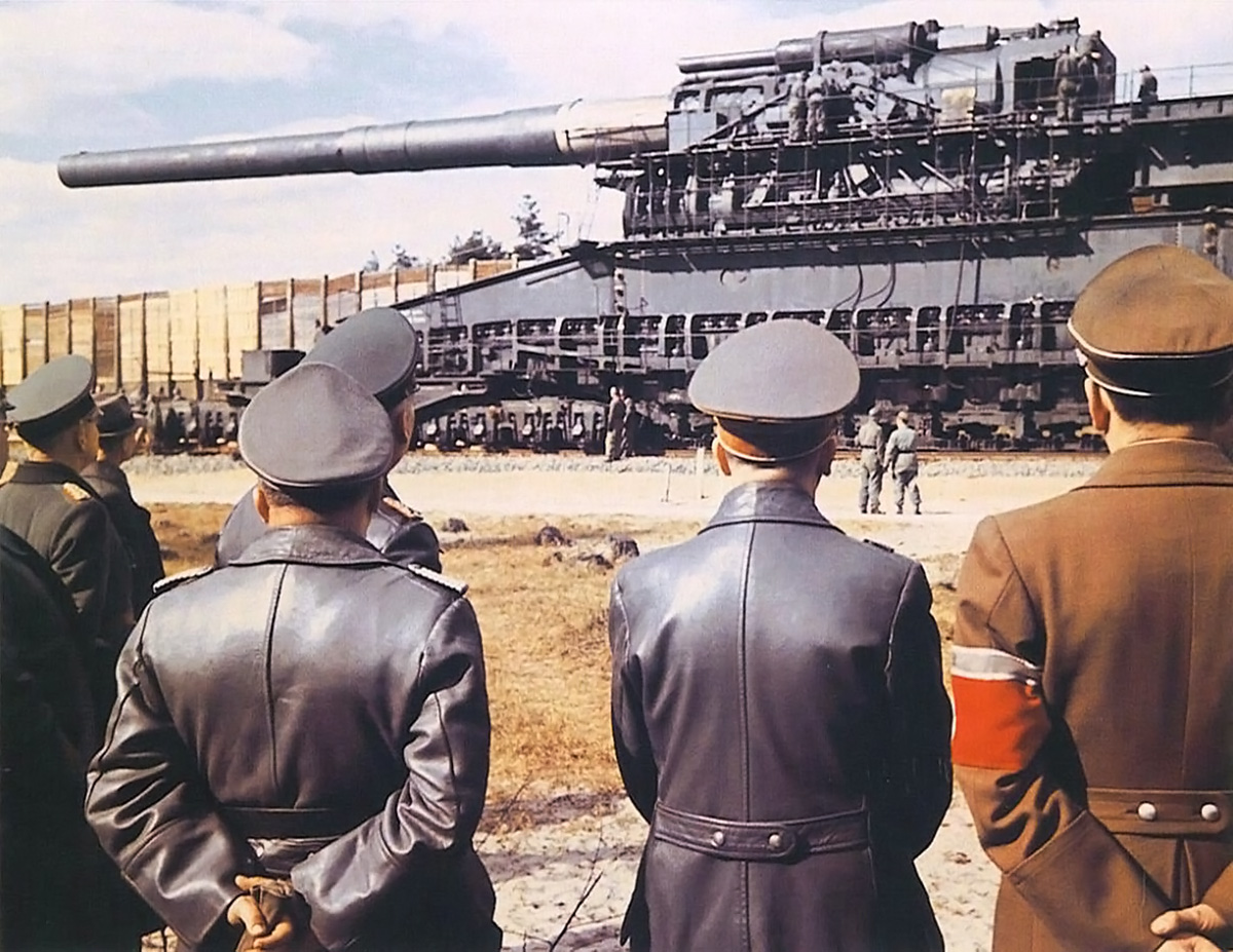
The Krupp 80 cm Kanone (E) Schwerer Gustav / Dora being readied for a test firing on 19 March 1943 at Rügenwalde, Germany. Albert Speer (right), Adolf Hitler (second from right), and a number of other officials observed the firing. Hitler referred to the impractical gun as “meine stählerne faust (my steel fist).”
After studying details of Maginot Line fortifications that were published in French newspapers, it became apparent to German Wehrmacht (combined armed forces) planners that they did not possess any weapon capable of penetrating the fortifications. In 1935, the Wehrmacht requested Friedrich Krupp AG (Krupp), a heavy industry conglomerate in Essen, Germany, to prepare ballistics reports for guns firing 27.6, 31.5, 33.5, and 39.4 in (70, 80, 85, and 100 cm) shells. The goal was to fire the gun outside of the enemy’s artillery range and be able to penetrate 23 ft (7 m) of reinforced concrete or 3 ft (1 m) of steel armor. The Krupp factory dutifully ran the calculations and supplied the requested information but took no further action.
In March 1936, Adolf Hitler visited the Krupp factory and asked Gustav Krupp (von Bohlen und Halbach), head of the Krupp organization, what type of weapon was needed to smash through the Maginot Line. Krupp, recalling the recent report, was able to answer Hitler’s question in some detail. Krupp explained that a 33.5 in (80 cm) railway gun could be constructed and would be able to defeat the Maginot Line. After Hitler’s visit, Krupp directed his design staff to begin the layout of such a weapon. Erich Müller was the head of the artillery development department at Krupp and began working on the gun’s design.
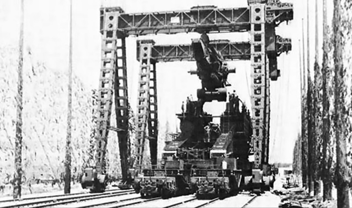
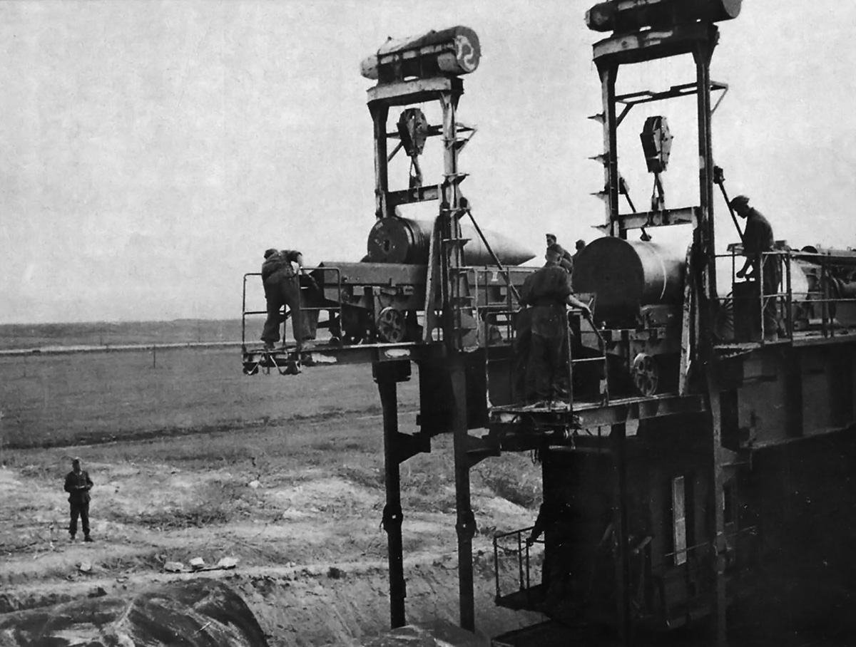
Nicknamed Dora by its crew, the massive gun was broken down into 25 pieces and transported by rail to its firing location. Two gantry cranes were used to reassemble the gun. Here, the cradle is being positioned into the carrier. Note the three normal railroad tracks and the special track for the cranes.
In early 1937, Krupp met with Hitler and presented him with the design for the 33.5 in (80 cm) railway gun. Hitler approved of what he saw, and the German Army High Command (Oberkommando des Heeres) commissioned Krupp to build three guns under the designation 80 cm Kanone (E). However, the guns quickly became known as Schwerer Gustav (Heavy Gustav), named after Gustav Krupp. Hitler wanted the first gun to be ready by March 1940.
The Schwerer Gustav was an absolutely huge weapon. The rifled barrel consisted of two halves, with the rear half covered by a jacket. The complete barrel was 106 ft 7 in (32.48 m) long, and its rifling was .39 in (10 mm) deep. Attached to the rear of the barrel was the cradle and breechblock. Mounted to the cradle were four hydraulic recoil absorbers. Trunnions held the gun’s cradle in two huge carriers and enabled the barrel to be elevated from 0 to 65 degrees. Each carrier was supported by four railroad trucks: two in the front and two in the rear. Each of the eight trucks was made up of five axles, giving the Schwerer Gustav a total of 80 wheels that were carried on two parallel sets of railroad tracks. The gun used a diesel-powered generator to provide power to run its systems. The Schwerer Gustav was 155 ft 2 in (47.30 m) long, 23 ft 4 in (7.10 m) wide, and 38 ft 1 in (11.60 m) tall. The barrel, cradle, and breech weighed 881,848 lb (400,000 kg), and the complete gun weighed 2,976,237 lb (1,350,000 kg).
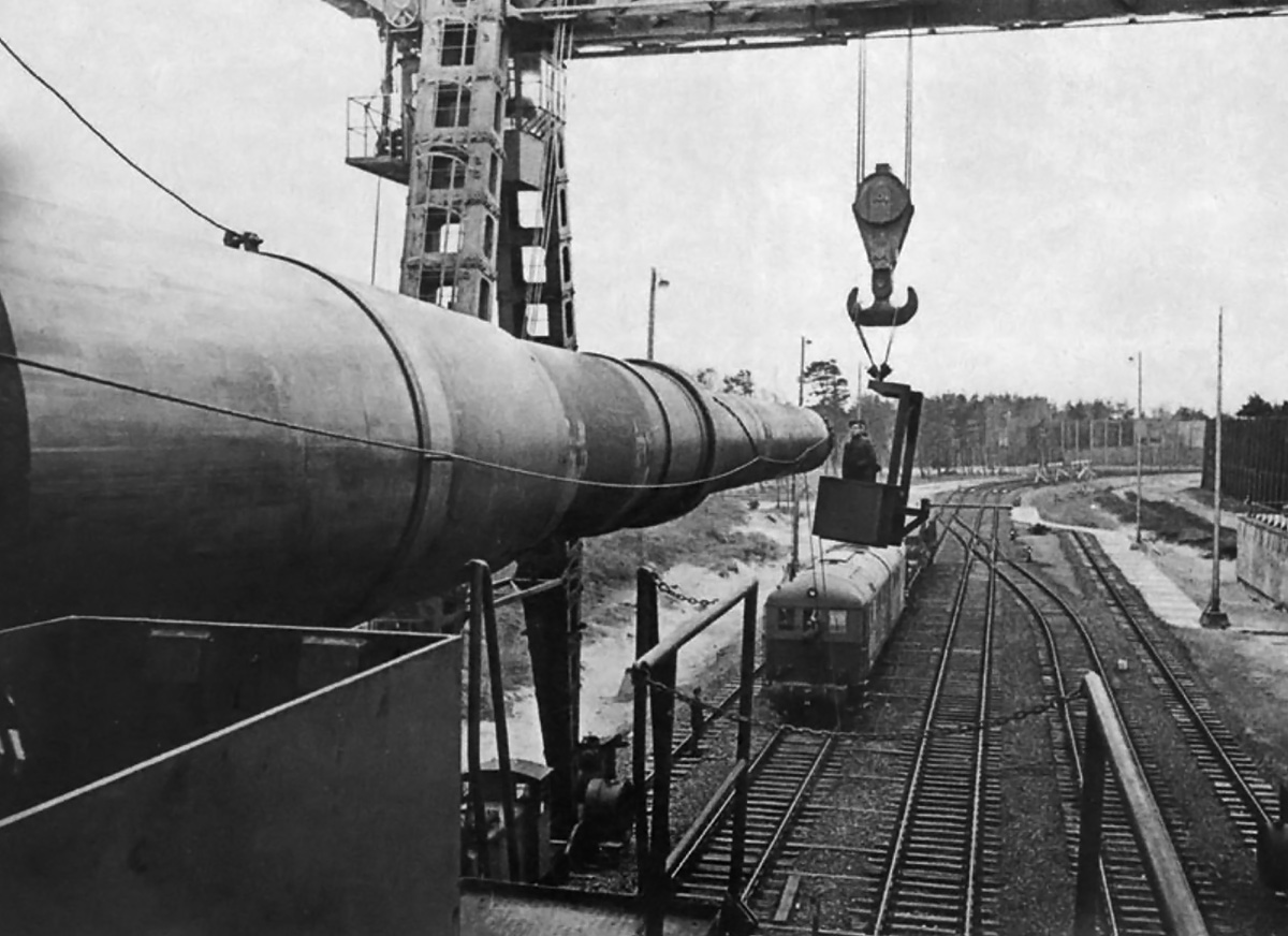
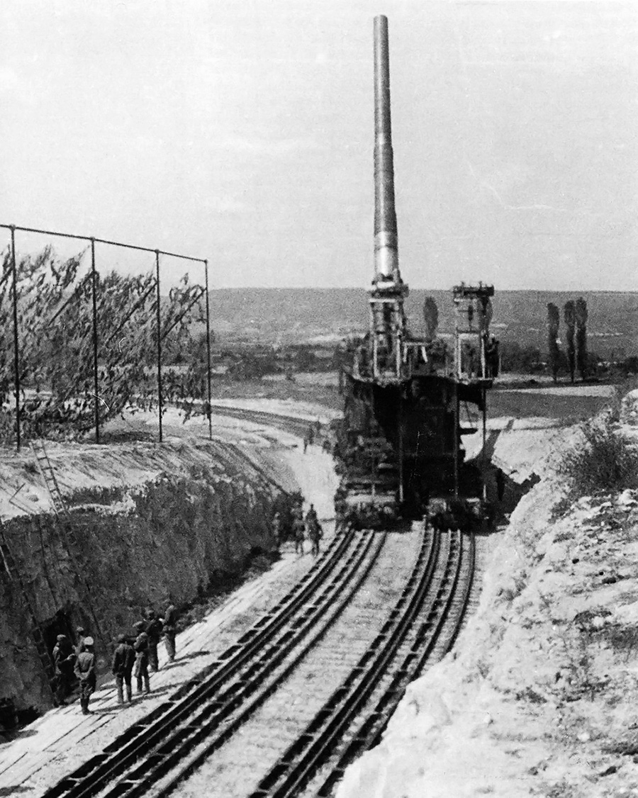
This image gives a good view of the tracks needed to assemble the Schwerer Gustav. One pair of D 311 locomotives is positioned in front of the gun.
In addition to needing parallel tracks, the Schwerer Gustav required its track to be curved up to 15 degrees. The gun had no built-in ability to traverse, so horizontal aiming (azimuth) was accomplished by moving the entire gun along the curved track. Extra bracing was added to the inside rail of both tracks along the shooting curve. This bracing helped prevent the tracks from being damaged due to the gun’s recoil. A massive effort was needed to transport and set up the Schwerer Gustav for firing.
The gun was broken down and transported on 25 freight cars, which did not include crew or supplies. Near where the gun was to be deployed, a spur line was laid from the main rail line. Three parallel tracks were then laid where the Schwerer Gustav was to be assembled. Two of the tracks supported the gun, and the third track allowed for parts and equipment to be brought in. A single rail was laid on both sides of the three parallel tracks. These widespread rails were for two gantry cranes to take parts from the third track and move them in position to assemble the Schwerer Gustav. Two parallel tracks extended from the assembly point to the firing position of the Schwerer Gustav. Dirt was piled up high on both sides of the double track to protect the gun from attack and allow it to be covered by camouflage netting. It took around 250 men 54 hours to assemble the Schwerer Gustav, and it took weeks for 2,000 to 4,500 men to lay the needed tracks and prepare the gun’s firing position. In addition, two Flak (Flugabwehrkanone or air defense cannon) battalions were needed to protect the gun from an aerial assault.
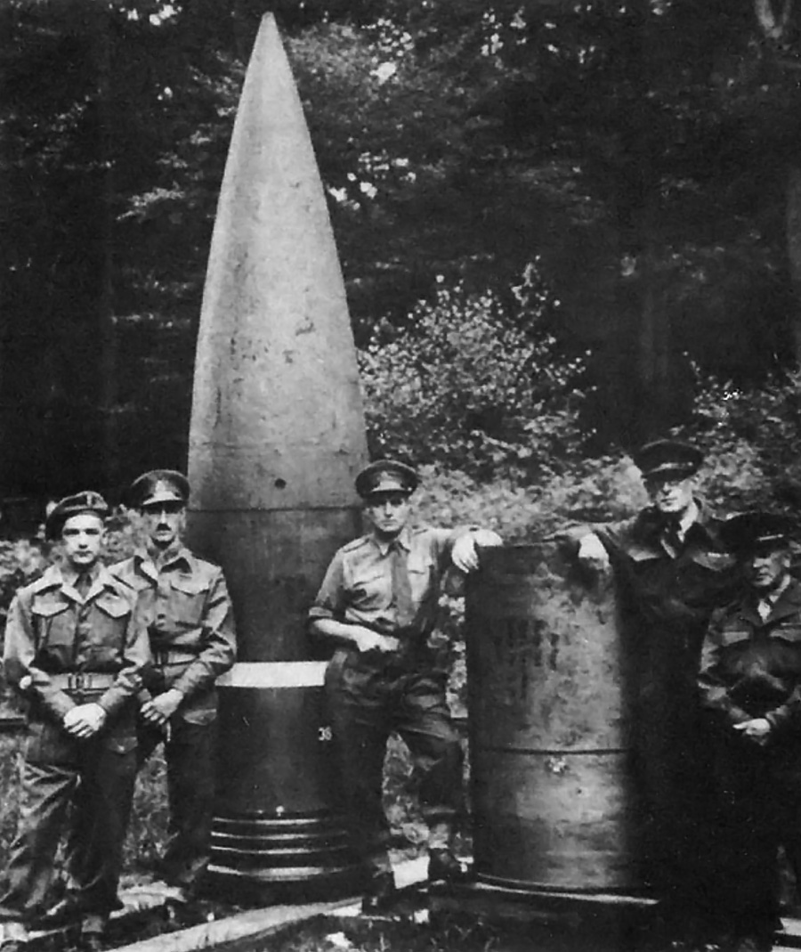
Allied soldiers pose in front of a captured projectile (left) and an obturation case (right). The projectile had a ballistic nose cone made of aluminum.
Krupp built special diesel-electric locomotives to move the Schwerer Gustav into firing position and to transport supplies. These locomotives were designated D 311, and two were paired together to act as a single unit, for a total of four engines to move the gun. Each locomotive was powered by a 940 hp (700 kW) six-cylinder MAN diesel engine. The engine ran a generator that provided power to traction motors mounted on the locomotive’s bogies. Ammunition was delivered via the twin rails behind the Schwerer Gustav. Hoists on the back of the gun would lift the ammunition to the firing deck. The shell was hoisted up one side of the gun, and the powder bags and a brass obturation case were hoisted up the other side. A hydraulic ram loaded the shell into the breach, followed by the powder bags and the case. Once loaded, the gun was raised into firing position. It took 20 to 45 minutes to load the gun and prepare it for firing. Only 14 to 16 shots could be fired each day.
Two types of shells were fired from the Schwerer Gustav: armor piercing (AP) and high explosive (HE). The AP rounds were 11 ft 10 in (3.6 m) long and were fired with 4,630 lb (2,100 kg) of propellant. The AP round was made of chrome-nickel steel. It weighed 15,653 lb (7,100 kg) and carried 551 lb (250 kg) of explosives. The AP shell had a muzzle velocity of 2,362 fps (720 m/s) and a maximum range of 23.6 miles (38 km). At maximum range, the AP projectile reached an altitude of around 39,370 ft (12 km) and was in the air for two minutes. The HE ammunition was around 13 ft 9 in (4.2 m) long and was fired with 4,938 lb (2,240 kg) of propellant. The HE rounds weighed 10,582 lb (4,800 kg) and carried 1,543 lb (700 kg) of explosives. The HE shell had a muzzle velocity of 2,690 fps (820 m/s) and a maximum range of 29.2 miles (47 km). Upon impact, the HE projectile created a crater some 33 ft (10 m) wide and deep. The muzzle velocity for both the AP and HE shells was over twice the speed of sound, and both were fitted with an aluminum alloy ballistic nose cone. Spotter aircraft were used to direct the gun’s fire and assess the results.
Construction of the Schwerer Gustav started in the spring of 1937, but forging the huge and complex barrel resulted in serious delays. By 1939, Alfried Krupp (von Bohlen und Halbach) began to take over company leadership from his father, whose health had begun to fail. In late 1939, testing started on sample components, and the gun’s AP projectile was able to successfully penetrate 23 ft (7 m) of concrete or 3 ft (1 m) of steel. It was obvious that the Schwerer Gustav would not be ready by the March 1940 deadline Hitler had requested.
Shells and propellant for the gun were delivered by rail and hoisted up to the firing deck. The shell is on the far side, and the case with powder bags is in front of it (to the right). It took 20 to 45 minutes to reload the gun and prepare it for firing.
In May 1940, Germany invaded Belgium and France. Since the Maginot Line ended at Belgium, rather than extending to the English Channel, Germany was able to simply go around the static fortifications and enter France. On 25 June 1940, France surrendered to Germany.
With the fall of France, the Schwerer Gustav was no longer needed, but discussions ensued regarding other fortifications that the gun could be used against. Many in the Wehrmacht felt the gun was impractical and not worth the resources its construction consumed, let alone the manpower needed to deploy the gun. However, the Schwerer Gustav had become one of Hitler’s personal projects, so its development continued. Alfried Krupp hosted Hitler for a test firing during the gun’s acceptance trials in early 1941 at Rügenwalde, Germany (now Darłowo, Poland). Further tests and development continued through 1941. Some sources indicate that 250 rounds were fired from the gun during its testing.
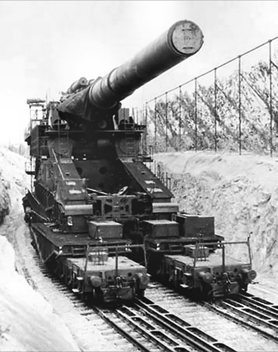
The gun was positioned on a shooting curve to allow for horizontal aiming. Rectangular braces were positioned on both sides of the inner rails to protect the tracks from the forces of firing the gun.
On 8 January 1942, Schwere Artillerie-Abteilung (E) 672 (Heavy Artillery Division E 672) was established with 1,420 men and with Oberst (Colonel) Robert Böhm as its commander. The unit was formed to deploy the Schwerer Gustav. As the artillerymen worked on the gun, they called it “Dora,” and the nickname stuck. From that time on, the gun was typically referred to as Dora, rather than Schwerer Gustav. The different names led to some confusion regarding how many guns were built and when they were used. German sources typically indicate that Dora was a nickname from the artillerymen and that only one gun was ever deployed. However, many English sources state that Gustav and Dora were the first and second guns built and that the Dora gun was named in honor of Erich Müller’s wife.
In February 1942, the division was sent to Bakhchisaray in the Crimean Peninsula, then part of the Soviet Union. The gun was to be used on the port city of Sevastopol, 18.6 miles (30 km) southwest of Bakhchisaray. Sevastopol had been under siege by German forces since November 1941. Five separate trains were used to transport the gun, the division, ammunition, supplies, and workshops to the deployment site. The Schwerer Gustav arrived in early March. In May, German troops and civilian workers laid a 1.2 mile (2 km) long access track to the firing site, followed by parallel tracks .75 miles (1.2 km) long for gun assembly and deployment. Once the track was ready, assembly of the gun commenced.
On 5 June 1942, the Schwerer Gustav fired its first round at Sevastopol, and 13 additional shots followed that day. On 6 June, the Schwerer Gustav achieved the highpoint of its career. An ammunition magazine at White Cliff suffered a direct hit from the Schwerer Gustav. The magazine was buried 98 ft (30 m) under Severnaya Bay and had 33 ft (10 m) of concrete protection. The AP round passed though the water, ground, and concrete before detonating the magazine. At least one ship was also sunk after being damaged by blast waves from the impact of nearby shells.
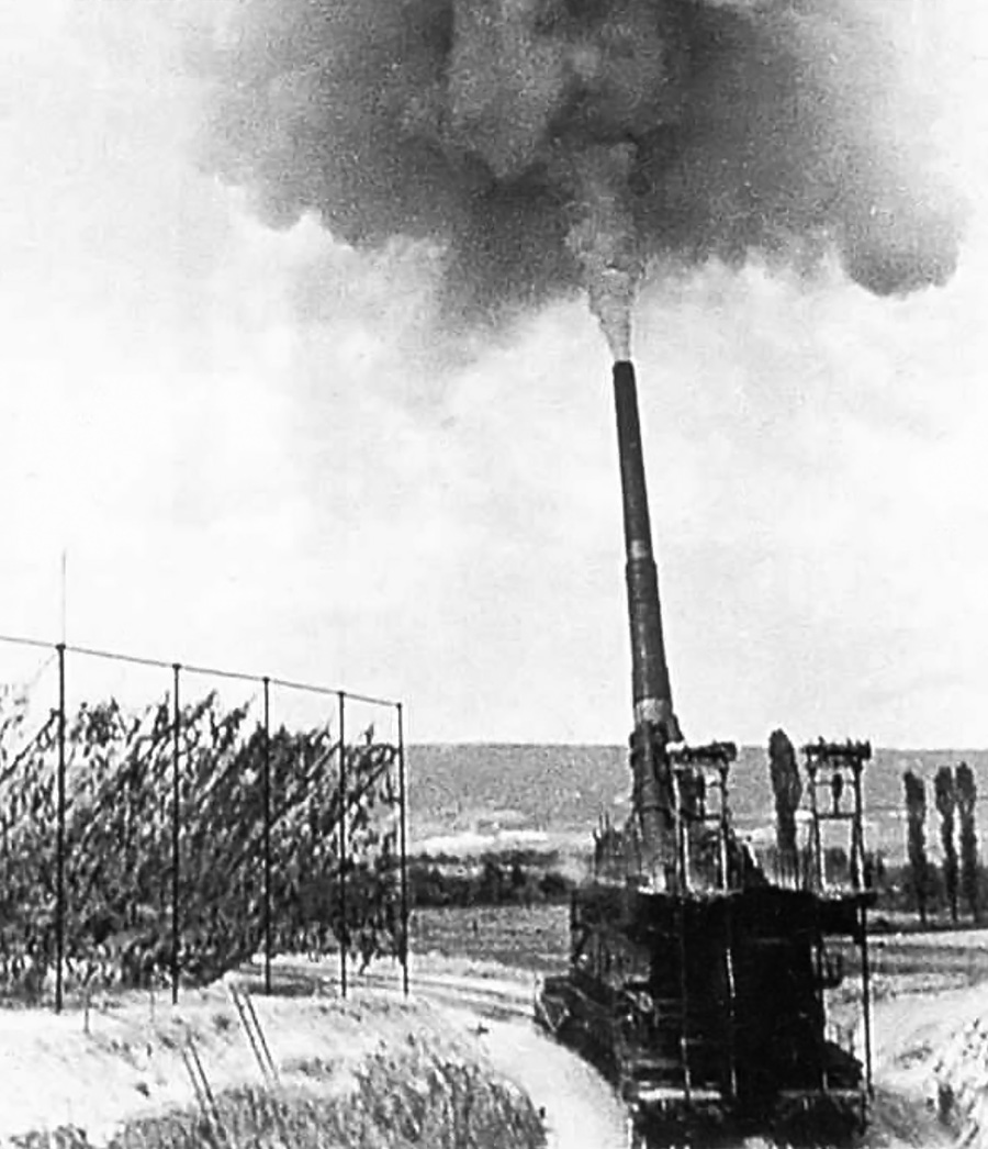
The Schwerer Gustav could fire a 15,653 lb (7,100 kg) AP shell 23.6 miles (38 km) or a 10,582 lb (4,800 kg) HE shell 29.2 miles (47 km). A spotter aircraft directed fire and assessed the results.
The gun was used on three additional days before its ammunition was exhausted. The Schwerer Gustav fired a total of 48 shells at the city, and its barrel had become worn. Some sources claim that the barrel had a 300-round life and was the same one that had fired the 250 test rounds. Other sources state the barrel was new and should have been able to fire 100 shots before it became worn, but signs of wear were seen after as few as 15 shots. Regardless, the Schwerer Gustav’s barrel was replaced with a spare, and the original barrel was transported back to Germany for repairs. Of the 48 rounds fired, only 10 fell within 197 ft (60 m) of their target, with the most off-target shot landing 2,428 ft (740 m) from its intended point of impact. However, each huge shell caused massive damage all around its impact site.
A few weeks after Sevastopol fell on 4 July 1942, Gustav Krupp gave the first Schwerer Gustav to Hitler as a personal gift and a sign of his support and allegiance to the Third Reich. The Krupp company would only accept payment for subsequent guns. The Schwerer Gustav was moved and redeployed for a planned offensive against Leningrad, which was also under siege. The gun had been assembled and placed in firing position, but its planned use was cancelled. The Schwerer Gustav was disassembled and taken back to Rügenwalde.
The gun was overhauled, and an improved, lined barrel was fitted. A test firing on 19 March 1943 at Rügenwalde was attended by Hitler, Albert Speer, Alfried Krupp, and a number of other officials. Two shots were fired, with the second shell impacting 29.2 miles (47 km) away. The Schwerer Gustav was then disassembled and placed in storage near Chemnitz, Germany in September 1943. The gun remained there until 14 April 1945, when it was destroyed by German troops one day before US soldiers captured the area. Parts of the Schwerer Gustav were recovered by the Soviets and supposedly transported to Russia. The second Schwerer Gustav was reportedly completed but never deployed. In March 1945, it was moved from Rügenwalde to Grafenwöhr, Germany, where it was destroyed on 19 April 1945.
While it was a powerful weapon, the Schwerer Gustav required a tremendous amount of resources for its construct and deployment. Its size and complexity severely limited where and when the gun could be deployed and also made it very susceptible to aerial attack.
Around November 1943, plans were initiated to use a cannon to shell Britain from across the English Channel. It was decided that the third Krupp 80 cm Kanone (E) would be built as the gun for this purpose. In order to send a shell 99 to 124 miles (160 to 200 km), a projectile 20.5 in (52 cm) in diameter and weighing 1,499 lb (680 kg) would be shot out of a barrel 157 ft (48 m) long. This gun was named Länger Gustav (Longer Gustav). The gun was damaged during a bombing raid while it was still under construction. Some components for the Länger Gustav were discovered at the Krupp factory in Essen by Allied troops in 1945.
In December 1942, Krupp proposed a self-propelled 80 cm Kanone (E) known as the Landkreuzer P. 1500 Monster. The P. 1500 used the same 31.5 in (80 cm) main gun as the Schwerer Gustav, but it also had two 5.9 in (15 cm) sFH 18.1 L/30 field guns and a number of 15 mm MG151/15 cannons. Powering the P. 1500 were four 2,170 hp (1,618 kW) nine-cylinder MAN M9V 40/46 diesel engines. The P. 1500 was 137 ft 10 in (42 m) long, 59 ft 1 in (18 m) wide, and 23 ft (7 m) tall. True to its name, the Monster weighed 3,306,930 lb (1,500,000 kg). Requiring a crew of over 100, the machine had an estimated top speed of 9.3 mph (15 km/h) and a range of 31 miles (50 km). The P. 1500 project was cancelled in 1943 by Albert Speer, the Minister for Armaments, before any serious work had been done.
After the war, Alfried Krupp and Erich Müller, the gun’s designer, were sentenced to 12 years in prison for crimes against humanity by participating in the plundering, devastation, and exploitation of occupied countries and by participating in the murder, extermination, enslavement, deportation, imprisonment, torture, and use for slave labor of German nationals, prisoners of war, and civilians who came under German control. Krupp was pardoned after three years, and Müller was released after four years.
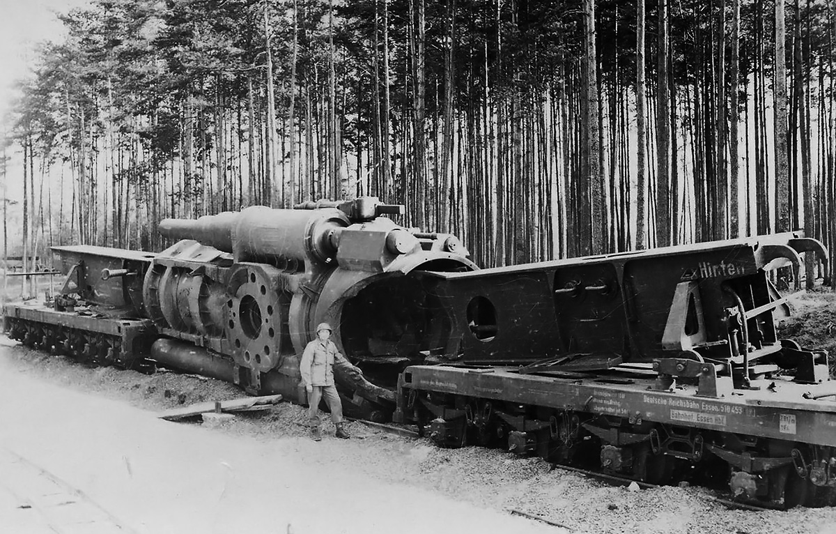
The first Schwerer Gustav gun was destroyed by German troops on 14 April 1945 to prevent its capture by US forces. Some sources state that the gun was recovered by the Soviets. A US soldier poses in front of the gun’s cradle. The girders attached to the cradle were used for transporting and mounting the cradle to the rest of the gun. The circular pad behind the soldier is a trunnion mount.
While the Schwerer Gustav was mechanically a well-engineered weapon, its requirements for use made it very impractical and nearly useless. The Maginot Line was easily bypassed, rather than penetrated, calling into question why the Schwerer Gustav was needed in the first place. However, Hitler liked the gun and called it his “steel fist.” It was the type of grandiose weapon that Hitler felt displayed the technological superiority of the Third Reich.
No large pieces of the Schwerer Gustav guns remain. However, a number of inert projectiles and cases are preserved in various museums. After the war, the D 331 locomotives were redesignated V 188 and used to haul freight for the West German Railway (Deutsche Bundesbahn).
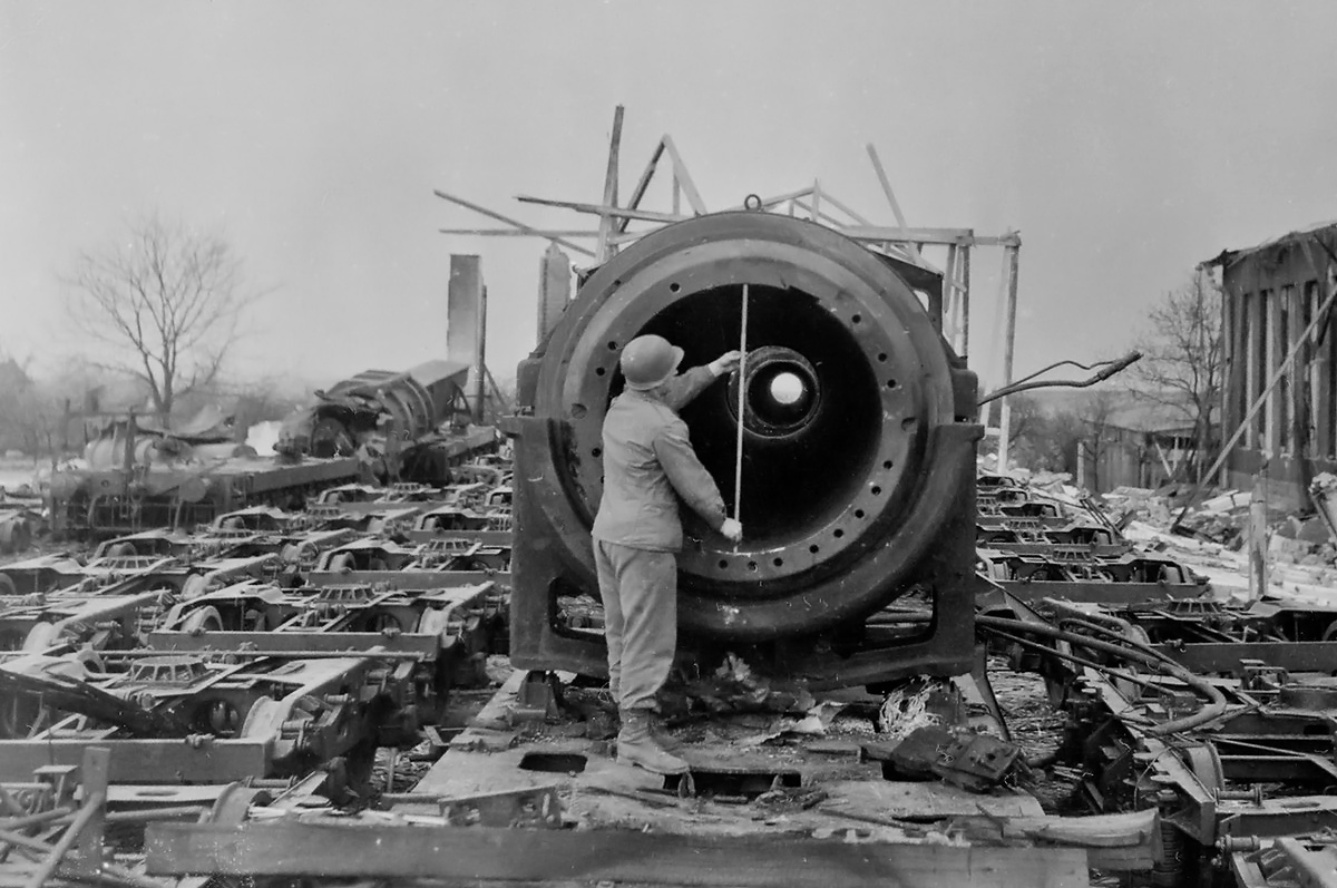
Germans destroyed part of the second Schwerer Gustav on 19 April 1945 to prevent its capture. A US soldier gives scale to the gun’s barrel. The second gun’s cradle, which was blown up, can be seen on the left.
Sources:
– http://de.wikipedia.org/wiki/80-cm-Kanone_(E)
– http://en.wikipedia.org/wiki/Schwerer_Gustav
– http://ww2db.com/weapon.php?q=89
– http://samilitaryhistory.org/vol124lw.html
– http://html2.free.fr/canons/dora.htm
– http://de.wikipedia.org/wiki/Wehrmachtslokomotive_D_311
– http://www.modellbahn.com/37283.V188.html
– http://www.e94114.de/V188.htm
– http://www.militaryfactory.com/armor/detail.asp?armor_id=480
– http://en.wikipedia.org/wiki/Landkreuzer_P._1500_Monster