Category Archives: Through World War I

Dubois Riout front wings down

DuBois-Riout Ornithopter

By William Pearce

When humans began to contemplate heavier-than-air flight, it was only natural to emulate birds. However, the complications of an ornithopter—using flapping wings to achieve flight—proved to be insurmountable. By 1900, most aviation pioneers focused their efforts on propellers and fixed wings; however, some persisted with the ornithopter.

Riout 1911 Patent

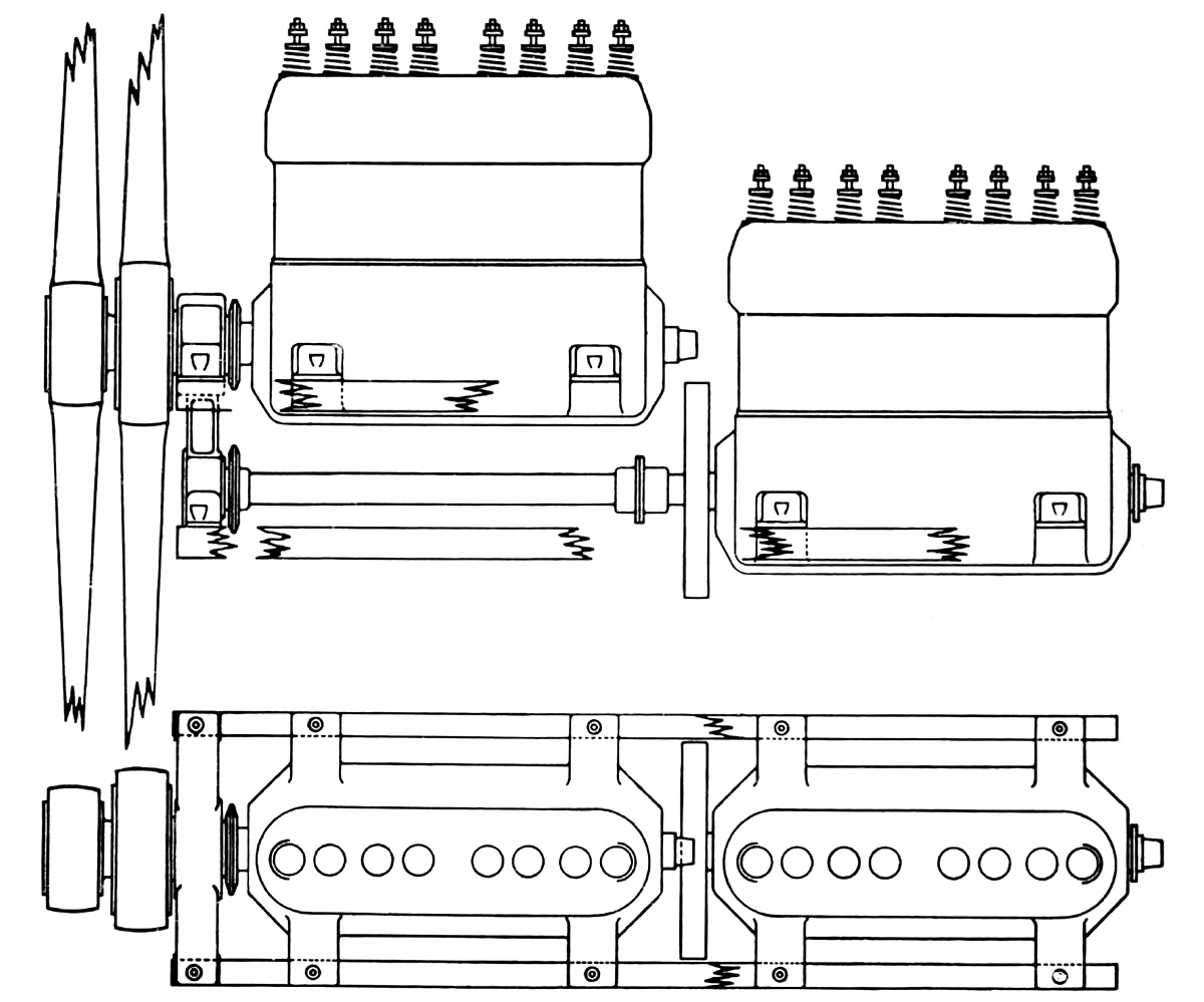
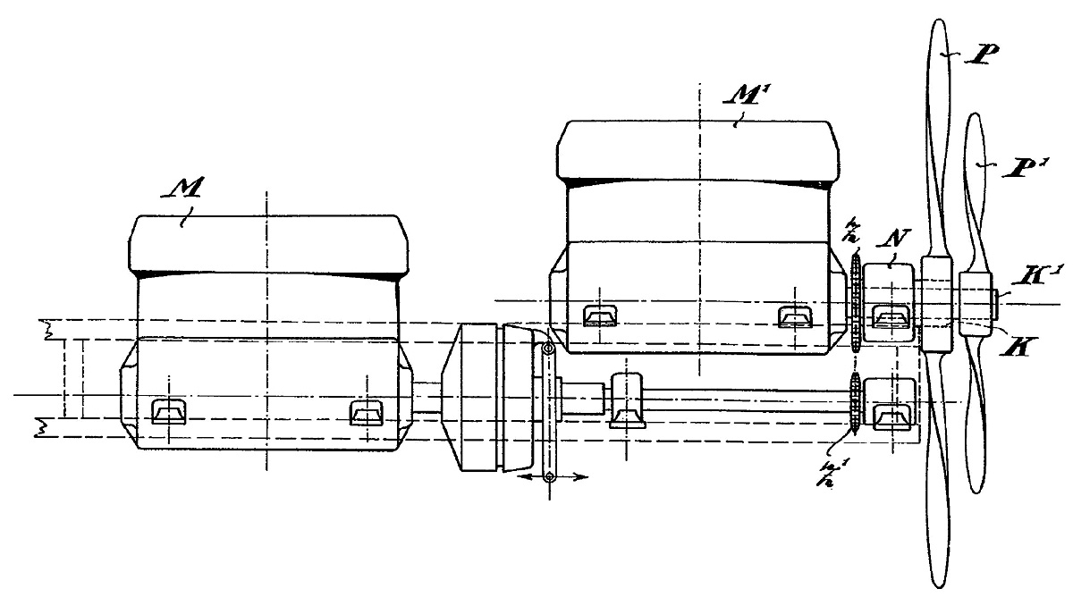
Drawings from René Riout’s US patent of 1911. Fig 1 shows the ornithopter design, which had a passing similarity to the aircraft built in 1913. Fig 2 and Fig 3 show the wing flapping mechanism. Fig 4 and Fig 5 show the wing in a gliding position. Fig 6 and Fig 7 show the wing warped for thrust.

In the early 1900s, French engineer René Louis Riout shifted his focus from automobiles to aviation. Initially, Riout designed models of gliders and propeller-driven aircraft, but his attention soon turned to ornithopters. By 1907, Riout was successfully flying his model ornithopter designs. In 1909, one of Riout’s models flew 164 ft (50 m) at an altitude of 10 ft (3 m). In 1910, his ornithopter model was flying 558 ft (170 m), and the distance expanded to 722 ft (220 m) in 1911.

In late 1910, Riout was granted French patent 419,140 for his flapping wing mechanism and ornithopter design. The same invention was patented in Great Britain (191117951) and the United States (1,009,692) in 1911. Riout’s patent described how power from an engine was geared at a reduced speed to a crankshaft. The crankshaft had two crankpins that were positioned 180 degrees apart. A connecting rod linked each crankpin to the pivoting mechanism of one wing. As the crankshaft turned and the crankpin moved to the horizontal position nearest the wing, the wing was moved to its highest position. As the crankpin moved to the horizontal position farthest from the wing, the wing moved to its lowest position. Thus, the up and down movement of the wing was controlled by the speed of the engine. The drive system incorporated a heavy flywheel to smooth out power pulses from the engine. For small aircraft, a heavy spring could be substituted for the flywheel.

Dubois Riout front

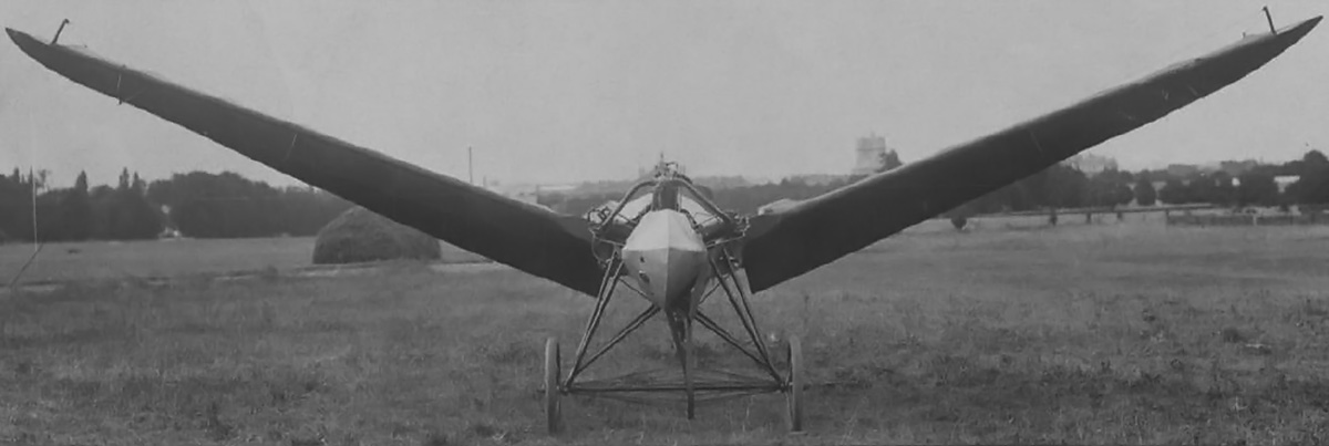
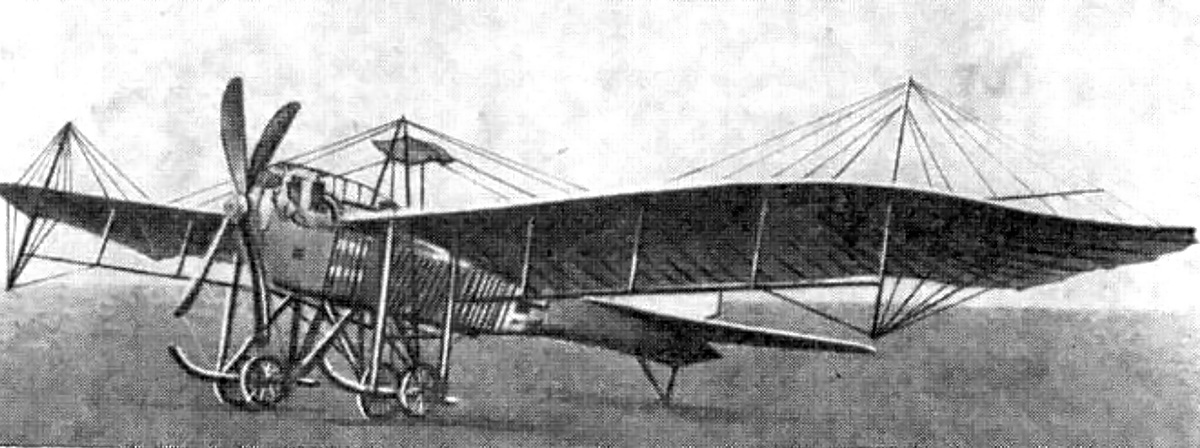
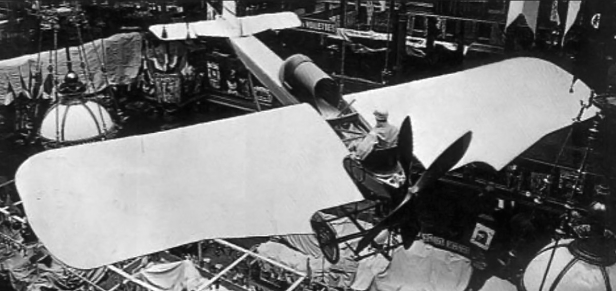
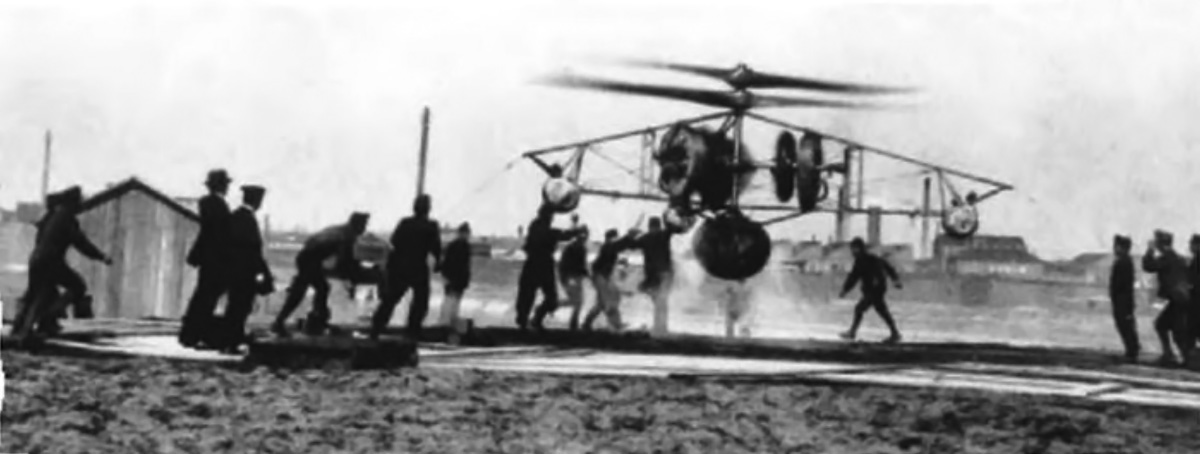
Front view of the DuBois-Riout ornithopter with the three-cylinder Viale engine. The engine cylinders can be seen protruding above the cowling. The wings are positioned around 20 degrees above horizontal. Note the quarter-turn belt drive for the wheel axle.

The patent details how the wings would warp as they moved. The upstroke was made in a neutral, gliding position. On the downstroke, the wing’s trailing edge would deflect up to provide thrust. Springs in the wing regulated the warp to match the power of the downstroke. A slow downstroke would result in the wing maintaining its glide form. The warp of the wing was greatest at the tip, tapering to very little warp at the root.

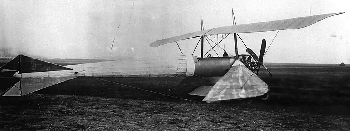
By 1913, Riout had partnered with Jean Marie DuBois, and a full-scale ornithopter was built. Exactly what role DuBois played in the creation of the ornithopter has not been found, but the resulting machine was known as the DuBois-Riout monoplane. The DuBois-Riout ornithopter had a slender, streamlined airframe that was made from tubular-steel and covered in fabric. A vertical stabilizer with a rudder protruded from below the fuselage. A horizontal stabilizer extended to the sides from the top of the fuselage and incorporated an elevator. The single-place cockpit was positioned between the ornithopter’s wings. The wings had a tubular-steel frame and were fabric-covered. The aircraft was supported by taildragger landing gear.

Dubois Riout front wings down

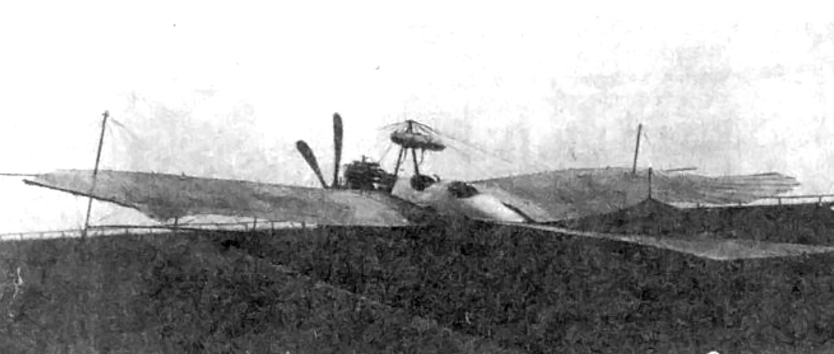
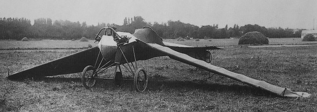
The ornithopter’s wings in the down position were about 20 degrees below horizontal, which was enough to make them contact the ground. This is why wing flapping would only be initiated after the aircraft was airborne, having been propelled to takeoff speed by the wheels. A shroud can be seen covering the top part of the drive belt.

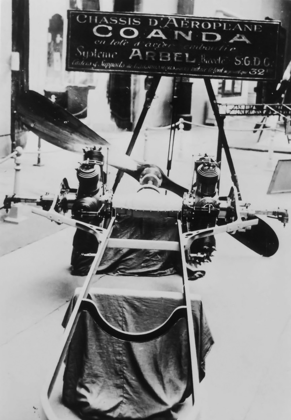
The ornithopter was powered by a three-cylinder Viale Type A engine. The three cylinders were spaced 65 degrees apart in a fan configuration. The air-cooled engine had a 4.13 in (105 mm) bore and a 5.12 in (130 mm) stroke. Its total displacement was 206 cu in (3.4 L), and it produced 35 hp (26 kW) at 1,500 rpm. The engine was positioned in the nose of the ornithopter and encased in a cowling, but its cylinders protruded into the air stream for cooling. The engine drove a crankshaft to flap the wings, just like the patent described.

A major problem facing ornithopter designs was how to start the takeoff roll and gain enough forward speed to achieve flight. Via a belt, the DuBois-Riout used engine power to drive the main wheels during the takeoff run. The drive pulley was positioned behind the engine, and the follower pulley was positioned on the main wheels’ axle and perpendicular to the drive pulley. The follower pulley was offset to the left so that its front edge was directly below the left side of the drive pulley. As the belt came off the rear of the follower, it traveled to the right to reconnect with the right side of the drive pulley. The belt twisting 90 degrees enabled the longitudinal rotation of the engine’s crankshaft to be converted to transverse rotation for the aircraft’s wheels. Once the ornithopter was up to speed, the machine was glided off the ground. Via clutches, engine power was transferred from the pulley to the flapping wings for sustained flight. The DuBois-Riout ornithopter had a 34 ft 5 in (10.5 m) wingspan and a predicted max speed of 84 mph (135 km/h). The machine weighed 794 lb (360 kg).

Dubois Riout side

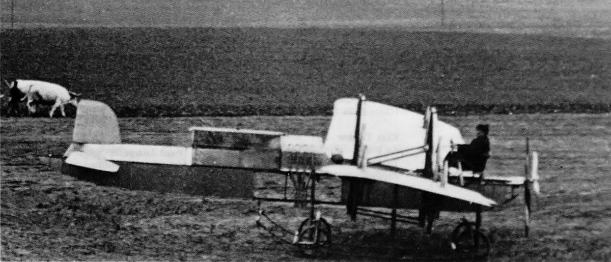
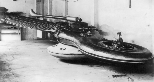
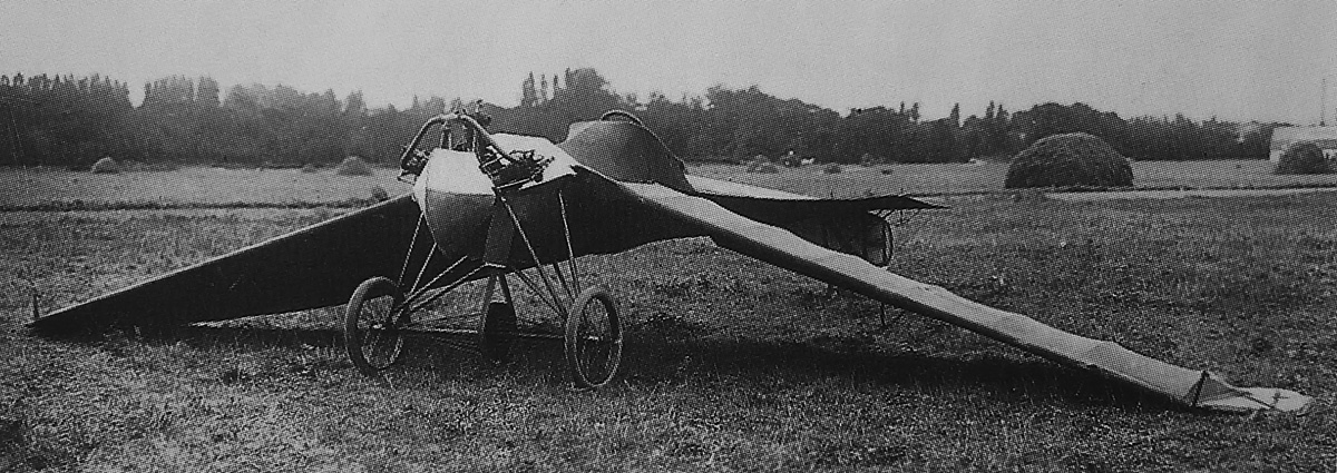
Side view of the DuBois-Riout ornithopter illustrates the vertical stabilizer under the fuselage and the elongated horizontal stabilizer. Note the large pulley on the wheel’s axle.

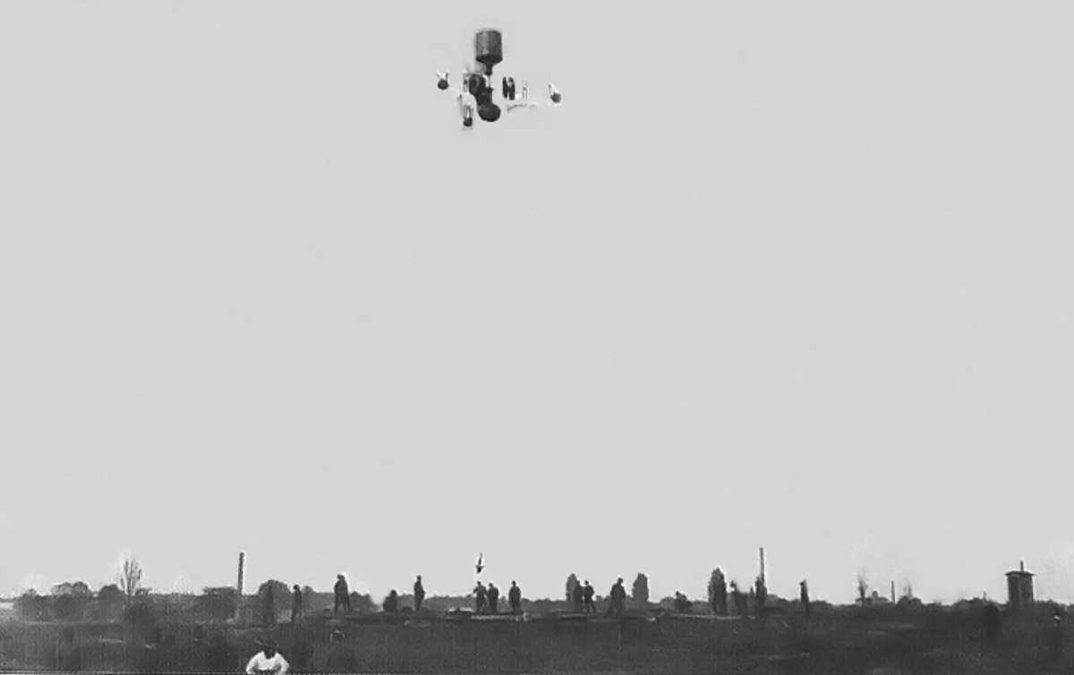
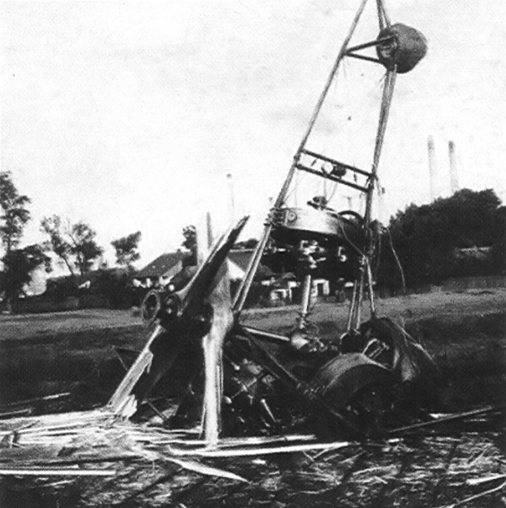
In late 1913 or early 1914, Riout initiated tests of the ornithopter but encountered issues with the engine. It is not clear if the engine was not running correctly or if more power was needed. Before the issues were resolved, Riout left to serve in World War I. In 1916, Riout was granted permission to restart tests on the ornithopter. A 50 hp (37 kW) Gnome-Rhône engine was acquired and installed in the aircraft. No information has been found as to what modifications were made to the ornithopter to handle the rotary engine or its gyroscopic torque. Reportedly, the ornithopter made it into the air but quickly came down hard and was wrecked. No one was injured in the mishap, but Riout needed to return to the war, and no further work was done on the ornithopter.

One might think that with the destruction of the DuBois-Riout machine and conventional aircraft proving their worth throughout World War I, Riout would move away from the ornithopter design. However, he persisted, but 20 years passed before his next ornithopter, the Riout 102T Alérion, was built.

Dubois Riout rear

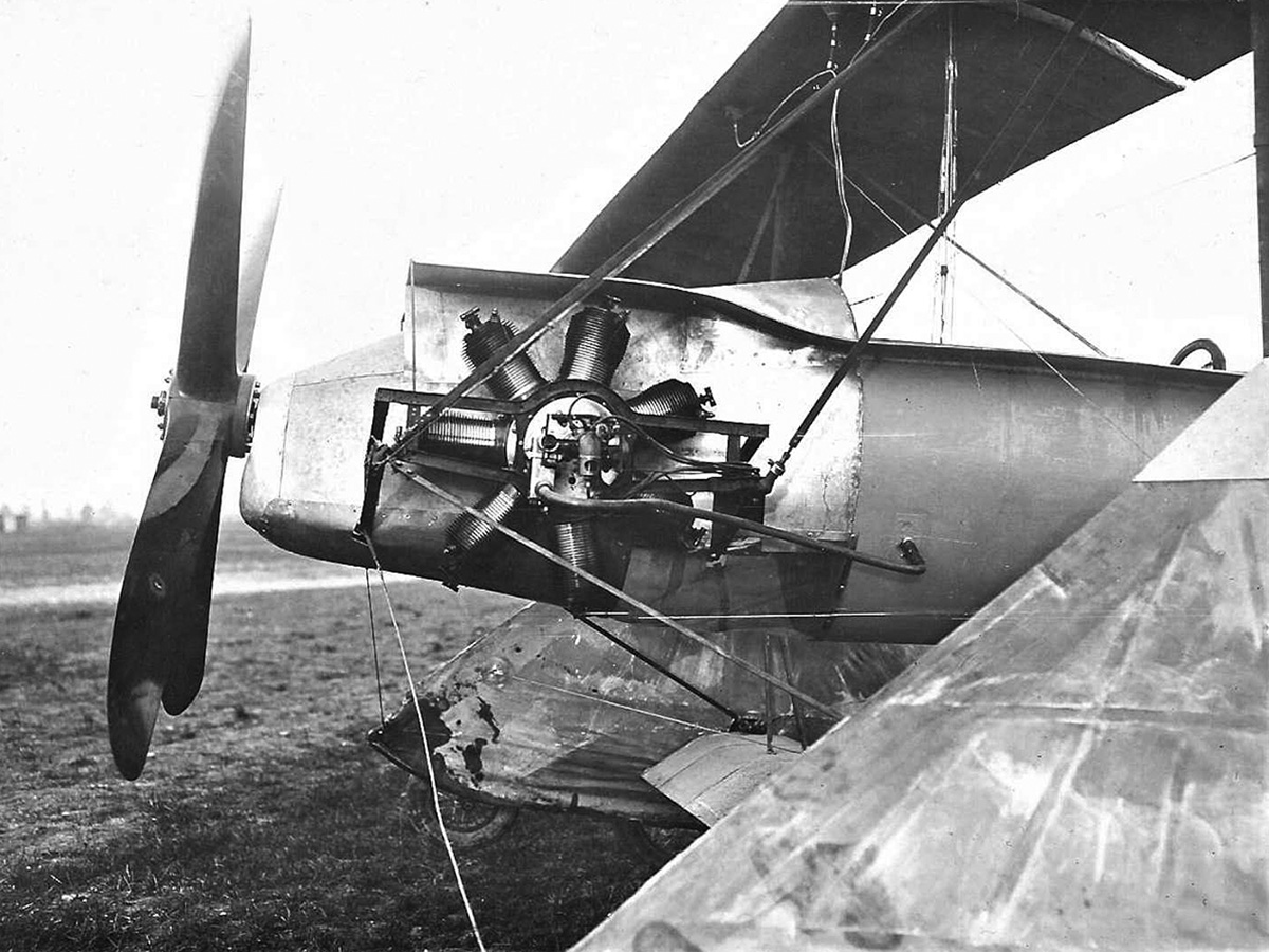
The ornithopter’s rudder can be seen in this rear view. Note the large control wheel in the cockpit and the fabric gap between the wings and fuselage.

Sources:
– “Flying Machine with Flapping Wings” US patent 1,009,692 by René Louis Riout (granted 21 November 1911)
– “French Monoplane with Flapping Wings” Popular Mechanics (February 1913)
French Aeroplanes Before the Great War by Leonard E. Opdycke (2004)
Rotary Wing Aircraft Handbooks and History Volume 11: Special Types of Rotary Wing Aircraft by Eugene K. Liberatore (1954)
– “Avion à ailes battantes Riout 102T” by Christian Ravel Le Trait D’Union No 225 (January-February 2006)

Rumpler Loutzkoy-Taube front ground

Rumpler-Loutzkoy-Taube Aircraft

By William Pearce

Boris Loutzkoy (also spelled Lutskoi, Luskoy, Lutsky, and probably other ways) was a Russian engineer who went to Germany to continue his education in the 1880s. Initially, his main interests were with internal combustion engines and automobiles, but it was not long before Loutzkoy turned his focus and engineering talents to aviation.

Rumpler Loutzkoy-Taube front ground

The tandem-engine Rumpler-Loutzkoy-Taube employed coaxial propellers that rotated the same direction. The second engine can just be seen behind the first engine and between the wings. Note the aircraft’s double main wheels.

By 1911, he had teamed up with Rumpler Flugzeugwerke in Berlin, Germany to test an innovative propulsion concept. Loutzkoy’s idea was to use two engines to power separate propellers on a common shaft. Since the propellers shared the same shaft, they were coaxial. However, they were not contra-rotating, because they rotated the same direction. The propellers in Loutzkoy’s system were of different sizes and turned at different speeds. Loutzkoy believed this power arrangement would improve the aircraft’s low- and high-speed performance, with the twin propellers achieving a level of efficiency beyond what could be obtained with a single propeller of any size. In addition, two engines with separate propellers would provide a level of reliability well beyond that of a single power plant. At the time, engines were notoriously unreliable.

To test his theories, Loutzkoy made many modifications to a Rumpler Taube aircraft. The Taube (Dove) was designed in 1909 by Igo Etrich of Austria-Hungary. The aircraft first flew in 1910 and proved to be very stable. A number of manufacturers purchased licenses to build copies, and Rumpler probably produced the most. The Taube was a monoplane with a mostly wooden frame. The front of the aircraft and back to the cockpit was covered in metal, but the rest of the aircraft was fabric-covered. The Taube used wing warping for roll control.

Rumpler Loutzkoy-Taube front

This drawing of the Loutzkoy-Taube illustrates the aircraft’s similarity to a standard Taube. The obvious differences include the double propellers and two main gear wheels.

The Loutzkoy-modified aircraft was named the Rumpler-Loutzkoy-Taube. Changes from a standard Taube included a slightly modified and strengthened airframe, strengthened landing gear (including double wheels), and a slightly larger wing. These changes were made to handle the extra weight and power of a second engine. The approximate dimensions of the Loutzkoy-Taube were a wingspan of 49 ft 10 in (14.3 m) and a length of 34 ft 1 in (10.4 m). The aircraft weighed around 1,764 lb (800 kg) empty. The Loutzkoy-Taube had a top speed of 93 mph (150 km/h), about 31 mph (50 km/h) more than a standard Rumpler Taube.

Powering the Loutzkoy-Taube were two Argus Type 4 engines. The Type 4 was an inline, four-cylinder, water-cooled engine with a 5.51 in (140 mm) bore and stroke. The engine displaced 526 cu in (8.62 L) and produced 100 hp (75 kW) at 1,300 rpm. The two engines drove separate propellers that were mounted on a common shaft: the front engine drove the front propeller, and the second engine drove the second propeller. Both sets of propellers had two blades.

Rumpler Loutzkoy-Taube engines

A basic drawing of the engine installation in the Loutzkoy-Taube.

The front engine was positioned in its normal location, in the nose of the aircraft. However, rather than having its propeller mounted directly to the engine, a short extension shaft was used. The second engine was mounted behind and below the front engine. Power from the second engine was transferred to the front of the aircraft via an extension shaft that ran under the front engine. A sprocket on the end of the extension shaft was connected via a chain to the second propeller, which was positioned between the first propeller and the front engine.

Although the propellers turned the same direction, the second propeller was a larger diameter, turned at a slower rpm, and had a coarser pitch. The first propeller was 8 ft 2 in (2.5 m) in diameter, direct drive, and turned about 1,300 rpm. The second propeller was 9 ft 10 in (3.0 m) in diameter, had a .615 reduction through the chain-drive, and turned around 800 rpm. The aircraft could be flown on either engine if a failure occurred, but the intention was to have both engines operating at all times.

Rumpler Loutzkoy-Taube patent

A drawing from Loutzkoy’s patent shows the basic engine layout that was used in the Loutzkoy-Taube aircraft and includes a change-over gearbox. The gearbox was meant to provide braking after touchdown by reversing the rotation of the second propeller. However, such a gearbox was never installed in the aircraft.

In his German patent no. 263,059 (granted 29 October 1911), Loutzkoy explained how a change-over gearbox could be used to reverse the rotation of the second propeller. This feature would be used for braking after the aircraft landed. In flight, shortly before landing, the second engine would be stopped and the change-over gearbox engaged. The second engine could then be started on touchdown. Its propeller rotating in the opposite direction would slow the aircraft down. Most aircraft at the time did not have any brakes, and using the propeller as a brake would become common with turboprops. However, the reversing propeller idea was never implemented on the Loutzkoy-Taube aircraft.

Rumpler Loutzkoy-Taube Argus engines

Detailed right and left views of the Loutzkoy-Taube’s twin-Argus engine installation. Note the size difference of the propellers. The extension shaft and chain drive from the second engine to the larger propeller can clearly be seen.

The Loutzkoy-Taube was first flown in early 1912, possibly in February, at Johannisthal airfield, near Berlin. With a combined rating of 200 hp (149 kW), the Loutzkoy-Taube was one of the most powerful and fastest aircraft of its time. A number of subsequent flights were made, and Hellmuth Hirth was the pilot for most of the Loutzkoy-Taube’s flights. The aircraft passed an inspection test for the Russian Army on 8 March 1912, achieving a speed of 81 mph (130 km/h). The Loutzkoy-Taube was displayed at the Berlin Airshow in April 1912. However, engine drive issues continued to plague the aircraft. By 1913, Loutzkoy had moved on to another aircraft project. Nothing more was heard of the twin-engine Loutzkoy-Taube and its coaxial propellers.

While it was not the first twin-engine aircraft to fly, the Loutzkoy-Taube was certainly the first aircraft to fly using coaxial, non-contra-rotating propellers. A very small number of aircraft have used this method of propulsion, as it really does not have many advantages over a single propeller and has disadvantages over contra-rotating propellers. Still, Loutzkoy’s ideas demonstrate innovation and creativity in the early days of aviation.

Rumpler Loutzkoy-Taube rear

This rear view of the Loutzkoy-Taube illustrates the aircraft’s similarity, with the exception of the double propellers, to a standard Taube. Note the fuel tanks attached to the cabane strut above the cockpit.

Sources:
– “The Loutzkoy 200-Horsepower Monoplane” Daily Consular and Trade Reports (29 May 1912)
– “Rumpler-Taube mit Zwei-Motoren-Anlage System Loutzkoy” Flugsport (13 March 1912)
– “Polytechnische Rundschau: Rumpler-Taube mit Motoranlage nach System Loutzkoy” Dinglers Polytechnisches Journal (16 March 1912)
– “Flugzeug mit zwei gleichachsig und unmittelbar hintereinander angeordnetem Propellern” German patent no. 263,059 by Boris Loutzkoy (granted 29 October 1911)
Rumpler: zehn jahre deutsche Flugtechnik (1919)
Typenhandbuch der deutschen Luftfahrttechnik by Bruno Lange (1986)
Argus – Flugmotoren und Mehr by Wulf Kisselmann (2012)
http://rusaviagold.narod.ru/HISTORY/lutskoi.htm
http://alternathistory.com/samoletostroitelnyi-zavod-rumpler-flugzeugwerke-i-ego-razvitie-v-1908-1913-e-gody
http://flyingmachines.ru/Site2/Crafts/Craft26875.htm

Deperdussin-de Feure store rear

Deperdussin-de Feure Model 2

By William Pearce

Georges de Feure (originally Georges Joseph van Sluijters) was born in Paris, France to a Dutch father and Belgian mother. De Feure was an artist and designer but turned his attention to aviation after Louis Blériot made his historic flight across the English Channel on 25 July 1909. Armand Deperdussin was born in Belgian but lived in Paris. Deperdussin had made a fortune importing silk for French stores. Like de Feure, Deperdussin had become interested in aviation after Blériot’s Channel crossing. In 1909, the two men joined forces to build aircraft; de Feure was the designer, and Deperdussin provided financial backing.

Deperdussin-de Feure store front

The Deperdussin-de Feure model 2 hangs in the Au Bon Marché department store in Paris. Note the number “2” on the aircraft’s nose and the single landing skid.

Many sources refer to the partnership as De Feure-Deperdussin (DFD) and call the aircraft DFD1 and DFD2. However, a French patent for the for the pair’s second aircraft cites the business as the Société A. Deperdussin et de Feure, or the A. Deperdussin and de Feure Company. This substantiates other sources that refer to the association as Deperdussin-de Feure, which will be the name used in this article. Subsequent patents listed Deperdussin and de Feure individually and include Louis Béchereau when applicable. Béchereau was an early French aeronautical engineer who was hired to assist with Deperdussin-de Feure aircraft design.

The first aircraft designed by Deperdussin-de Feure has been described as a pusher with an arrow-shaped wing. This aircraft was not built, but it did serve as the basis for the pair’s second aircraft. Deperdussin-de Feure applied for a patent on 19 November 1909 that described their second aircraft; they were granted French patent 409,715 on 24 February 1910.

Deperdussin-de Feure store rear

This rear view of the Deperdussin-de Feure suspended over the store’s toy department shows there is no engine installed in the aircraft, and the wing is absent of flight controls. Note the two wide, two-blade, contra-rotating propellers.

The Deperdussin-de Feure model 2 aircraft was a pusher design that had a rear main wing and a front canard. The tail-first aircraft was made up of a wooden framework covered with fabric. In the middle of the fuselage was a radiator to cool the water from the four-cylinder engine. The radiator consisted of numerous copper tubes that arched from one side of the aircraft to the other; the radiator was modified several times throughout the life of the aircraft.

The engine was enclosed in a metal cowling and sat just behind the radiator. Reportedly, the engine produced 65 hp (48 kW) at 2,300 rpm and weighed 165 lb (75 kg). The manufacturer of the engine is not known, and its specifics do not match any engine from the time period. However, the engine does resemble four-cylinder engines built by Panhard-Levassor around that time, although the Panhard-Levassor engines produced peak power at a lower rpm and were heavier.

Deperdussin-de Feure Avialogs

The completed Deperdussin-de Feure with revised wing at Chamdry, France. Note the various trusses above and below the wings and that a second landing skid has been added. The two two-blade, contra-rotating propellers are still present. (Image via Avialogs.com)

A propeller shaft extended from the engine, traveled under the pilot’s seat, and terminated at a gearbox in the rear of the aircraft. The gearbox transferred the engine’s power to a set of contra-rotating propellers. The patent noted that the contra-rotating propellers would cancel engine torque and increase the aircraft’s stability. The patent also stated that the pitch of the rear propeller was greater than that of the front propeller to make efficient use of the increased airflow generated by the first propeller. Originally, two two-blade propellers were installed, but these were later replaced by two four-blade propellers.

According to the patent, the curvature of the wings’ inner sections could be warped symmetrically by the pilot to increase lift or drag. The outer sections of the Deperdussin-de Feure’s wings could be warped asymmetrically for roll control. The aircraft’s canard featured an all-moving elevator with an all-moving rudder positioned above.

Deperdussin-de Feure cockpit

The extensive trusswork for the Deperdussin-de Feure’s wings is displayed in this photo. The inclined track for the wing can be seen in the middle of the photo, just behind the first truss. Note the two two-blade propellers.

While the patent drawing shows a passenger seat mounted between the pilot’s seat and the engine, it does not appear that such accommodations were ever installed. The pilot’s seat was essentially mounted on top of the fuselage. A wheel in front of the pilot controlled wingtip warping for roll control. Wheels mounted on either side of the pilot controlled the elevator and inner wing warping. The rudder was controlled by a foot-operated bar.

The aircraft was supported by four wheels attached near a skid under the aircraft. The front wheels were steerable, and when the aircraft landed, all the wheels would pivot upward, allowing the skid to contact the ground. The friction created by the skid would slow the Deperdussin-de Feure aircraft to a stop. Originally, the aircraft had one skid, but a second was added later.

Appearing mostly complete, the Deperdussin-de Feure aircraft was displayed at the Au Bon Marché department store in Paris starting 12 December for the 1909 Christmas season. However, the aircraft lacked its engine, and 26 ft (8 m) long fake wings were installed just for the display. The aircraft was suspended from the ceiling above the store’s toy department and had a mannequin in the pilot’s seat. The aircraft’s unfinished components and its location above the toy department gave rise to the belief that it was just an elaborate model, and in a sense it was.

Deperdussin-de Feure side Chambry

The Deperdussin-de Feure ready for a flight attempt. It is difficult to determine which propellers are installed on the aircraft in this photo.

After the display, the aircraft was moved to a hangar at the Chambry airport 95 mi (150 km) northeast of Paris in March 1910. The hangar had been specially built and was designed and equipped under the supervision of Louis Blériot. By this time, the aircraft’s engine was installed, and an additional landing skid was added. With a span over 39 ft (12 m), the Deperdussin-de Feure’s true wings were fitted along with their wooden support trusses. The many changes incorporated gave rise to the belief that this was a different aircraft than the one displayed in the department store, and in a sense it was.

With the design of the new wings and their support trusses, the idea of increasing the wings’ lift by altering the curvature of the inner wing sections was discarded. A new method to increase lift was devised that altered the position and angle of the entire wing. Outlined in French patent 413,071 (applied for on 26 February 1910 and issued on 18 May 1910), each wing was attached to the aircraft’s fuselage via an angled track. The trusses held the left and right wings together, and the track allowed the wings to shift position relative to the fuselage. As the wings moved fore or aft, so too would the aircraft’s center of gravity. The track was inclined toward the front of the aircraft. As the wings moved forward, their angle of attack would increase, altering their center of pressure. Exactly how the system was operated is not recorded, and one can only imagine how wings shifting in position and angle would affect an aircraft in flight, especially in the early days of aviation.

Deperdussin-de Feure side

The Deperdussin-de Feure aircraft has now been modified with a ventral rudder and two narrow, four-blade, contra-rotating propellers.

The Deperdussin-de Feure aircraft was made ready for flight, and claims were circulated through the press that it could carry 661 lb (300 kg), had a 4,920 ft (1,500 m) ceiling, and that the military was interested in the machine. Many bystanders from nearby Laon would come out to Chambry in the hope of seeing de Feure pilot the aircraft into the air. Unfortunately, they were rewarded with only small hops of no more than 1.6 ft (.5 m). Four-blade propellers and an auxiliary, all-moving rudder positioned below the pilot were installed sometime during this period. In addition, a conventional cored radiator was tried. Tests at Chambry continued into June 1910. The aircraft was then moved to the Rheims airport 30 mi (50 km) southeast of Chambry, but a successful flight was still not achieved.

Frustrated by the lack of success, Deperdussin and de Feure had gone their separate ways by the end of 1910. Deperdussin started another aircraft company with Béchereau as the head designer. The company became the Société Pour L’Aviation et ses Dérivés (Society for Aviation and its Derivatives), better known as SPAD, and created some of the best aircraft of World War I. De Feure returned to his roots of design and artistry. Although he did envision a few other aircraft, only those meant as theater sets and costumes were constructed.

Deperdussin-de Feure rear Chambry

This rear view of the Deperdussin-de Feure displays the aircraft’s wing trusses, propellers, flight controls, and all-moving ventral rudder.

Sources:
Nederlandse Vliegtuigen Deel 1 by Theo Wesselink (2014)
– “Aéroplane monoplane” French patent 409,715 by Société A. Deperdussin et de Feure (granted 24 February 1910)
– “Perfectionnements aux aéroplanes” French patent 413,071 by Armand-Jean-Auguste Deperdussin, Georges-Joseph de Feure, and Louis Béchereau (granted 18 May 1910)
French Aeroplanes Before the Great War by Leonard E. Opdycke (2004)
http://www.avialogs.com/index.php/avialogs/100-years-old-unpublished-deperdussin-photos-found-at-garage-sale.html
https://en.wikipedia.org/wiki/Georges_de_Feure
https://en.wikipedia.org/wiki/Armand_Deperdussin

Coanda 1911 Monoplane prop

Coandă 1911 Monoplane

By William Pearce

Romanian Henri Marie Coandă is perhaps best known for observing the way a stream of fluid (such as air) is attracted to and will flow over a nearby surface. This component of fluid dynamics became known as the Coandă Effect. Coandă recognized this phenomenon while testing his first aircraft, built in 1910. This aircraft had a unique propulsion system that Coandă called a turbo-propulseur, and it is recognized as the first “jet” aircraft. A four-cylinder, 50 hp Clerget engine was used to power a rotary compressor that provided thrust. While there is some debate about the validity of the aircraft’s first and only flight and its subsequent destruction, the aircraft was certainly built to be propelled by a jet of fast-flowing air.

Coanda 1911 Monoplane front

Henri Coandă’s 1911 monoplane at the Concours Militaire in Reims, France in October 1911. Note the tandem main gear wheels.

Coandă’s second aircraft was built in France and completed in 1911. It utilized some salvaged and spare parts from the 1910 aircraft. The 1911 aircraft was originally designed to use a turbo-propulseur, but it was finished with a conventional propeller. The aircraft’s engine arrangement, however, was not conventional.

The 1911 aircraft was a rather large monoplane with a parasol wing mounted above the cockpit. A small lifting surface with a nickel steel spar joined the two main landing gear which were each comprised of two tandem wheels. Each main gear wheel set was encased in a large fairing. A single vertical strut made of nickel steel extended above each gear fairing and supported the wing. The wings had a nickel steel spar and were covered by fabric. The aircraft’s roll control was achieved by wing warping. Coandă’s 1911 aircraft had a cruciform tail similar to that used on the 1910 aircraft. The fins of the tail formed an X, and each fin had a trailing control surface that acted as both a rudder and an elevator.

Coanda-1911-Monoplane

This photo shows a detailed view of the Gnome installation on Coandă’s 1911 aircraft. Note the various struts and braces used on the aircraft. The aluminum-covered front fuselage is easy distinguished from the plywood-covered cockpit section. The aircraft’s control wheel can just be seen at right.

A rectangular support structure was formed by the upper and lower spar and the vertical struts above the wheels. The fuselage was suspended in this support structure by a series of brace wires and small struts. Additional wire bracing and struts supported the rest of the aircraft’s structure. Except for where the engines were mounted, the fuselage had a circular cross section that narrowed to a point at the tail. The front of the fuselage was covered by aluminum sheeting, the cockpit section was covered by plywood sheeting, and the rear of the aircraft was fabric-covered.

Perhaps the most unusual feature of Coandă’s 1911 monoplane was its engine installation and propeller drive. At the front of the aircraft were two Gnome 7 Gamma rotary engines. The seven-cylinder engines had a 5.1 in (130 mm) bore, a 4.7 in (120 mm) stroke, and a total displacement of 680 cu in (11.1 L). The 7 Gamma produced 70 hp (52 kW) at 1,200 rpm and weighed 194 lb (88 kg).

Coanda 1911 Monoplane engines

This photo shows an engine and gearbox arrangement similar to that used on Coandă’s 1911 monoplane. It is not clear when this photo was taken, but it may have been at the Salon de l’Aeronautique in Paris, France held mid-December 1911 through early January 1912. (Harry Stine image via New Fluid Technology)

The engines were installed front-to-front with their crankshafts perpendicular to the aircraft’s fuselage. While the engines’ cylinders were exposed to the slipstream for cooling, the front of the engines were enclosed within the fuselage. Mounted between the engines was a gearbox that drove a propeller shaft. The propeller shaft extended to the front of the aircraft where it drove a four-blade propeller. The engines and gearbox were mounted to a steel frame. Coandă claimed that the aircraft could fly with just one engine operating.

Most likely, the engines turned in opposite directions relative to each other. While this arrangement would cancel out the gyroscopic effects of the rotary engines along the pitch axis, it would induce some tendency to roll, even if just slightly. Some sources indicate the engines were “handed” —they rotated the same direction relative to each other. In addition to the complications in making a rotary engine run “backward,” the “handed” engine configuration would create a noticeable pitch moment on the aircraft as the engines were throttled (blipped), but it would also alleviate any tendency for the aircraft to roll. However, an early sketch of the engine arrangement indicates “handed” engines were not installed, and that a simple beveled gear arrangement was used to transfer power from the engines to the propeller shaft. Additionally, the transfer gearbox did not appear to be of sufficient size to accommodate the differential gearing needed for a “handed” engine arrangement.

Coanda 1911 Monoplane side

Note the cruciform tail and its control surfaces in this photo of the Coandă 1911 monoplane. Also, the plywood-covered cockpit section can be easily distinguished from the fabric-covered rear fuselage.

The 1911 Coandă monoplane had a wingspan of 53 ft 6 in (16.3 m) and a length of 41 ft (12.5 m). The aircraft had an empty weight of 1,036 lb (470 kg) and a maximum weight of 2,756 lb (1,250 kg). Two fuel tanks of around 30 gallons (115 L) each were housed in the center section of the wing. Reportedly, the aircraft could accommodate a pilot and two passengers. The estimated speed of the 1911 monoplane was 81 mph (130 km/h).

Coandă’s 1911 monoplane was tested in the Concours Militaire (Military Competition), held in Reims, France in late October 1911. Georges de Boutiny flew the aircraft, but it reportedly did not meet performance expectations. Later, wing extensions were added to the wheel fairings, turning the aircraft into a sesquiplane. Along with additional wire bracing, a vertical strut connected the end of the wing extension to the upper wing.

Coanda 1911 Monoplane prop

Mechanic George Bonneuil checks a Gnome engine as pilot George de Boutiny looks on from the cockpit. (Harry Stine image via New Fluid Technology)

A Coandă aircraft catalog from 1911 offered both the monoplane and sesquiplane versions of the aircraft with either 50 hp (37 kW) Omega or 70 hp (52 kW) Gamma Gnome rotary engines. It appears that only the single prototype of the Coandă 1911 aircraft was built, and exactly what happened to it is not known. The 1911 aircraft faded into history, and Henri Coandă went on to build other aircraft and further explore fluid dynamics.

Note: Some claim that Coandă’s 1911 aircraft was the first twin-engine aircraft. However, at least four other twin-engine aircraft preceded it in flight: the Daimler Lutskoy No. 1 (flew 10 March 1910, or possibly earlier), Edward Andrew’s twin (flew early 1910), Roger Sommer’s twin (flew 27 September 1910), and the Queen Speed Monoplane (flew 10 July 1911).

Coanda 1911 Monoplane extensions

This photo shows Coandă’s 1911 aircraft with its wing extensions. The extensions effectively made the aircraft a sesquiplane. Additional struts and braces for the extensions can be seen. Note the three people in the cockpit and also the warp of the wing tip.

Sources:
Henri Coandă and His Technical Work During 1906-1918 by Dan Antoniu, et al (2010)
French Aeroplanes before the Great War by Leonard E. Opdycke (1999)
Romanian Aeronautical Constructors 1905-1974 by Gudju, Iacibescu, and Ionescu (1974)
Henri Coanda: The Facts by New Fluid Technology (4.3 MB pdf)
http://flyingmachines.ru/Site2/Crafts/Craft28597.htm
http://en.wikipedia.org/wiki/Coand%C4%83-1910
http://en.wikipedia.org/wiki/Henri_Coand%C4%83
http://www.secretprojects.co.uk/forum/index.php/topic,18780.15.html

PKZ 2 engines 3

Petróczy-Kármán-Žurovec PKZ 2 Helicopter

By William Pearce

In 1916, Major Stephan Petróczy von Petrócz of the Austro-Hungarian Army envisioned replacing hydrogen-filled observation balloons with tethered helicopters. These helicopters would have been used as static observation platforms. Compared to hydrogen balloons, the helicopters’ were much less likely to catch fire, presented a smaller target for the enemy, increased operational readiness, required fewer ground and support crew, and eliminated the need for hydrogen generating equipment.

PKZ 2 with basket 3

Follow-on to the PKZ 1, the Petróczy-Kármán-Žurovec PKZ 2 is shown here with the observation basket attached above the rotors. This image was taken after the PKZ 2 was modified in May 1918 and the 120 hp (89 kW) La Rhône engines are installed.

To achieve his goal, Petróczy, along with Oberleutnant Dr. Theodor von Kármán and Ingenieurleutnant Wilhelm Žurovec, conceived the Schraubenfesselflieger (S.F.F) mit Elektromotor (captive helicopter with electric motor). This machine is now commonly refered to as the Petróczy-Kármán-Žurovec 1 (PKZ 1) helicopter. Built in 1917 and primarily designed by von Kármán and Žurovec, the PKZ 1 consisted of a rectangular frame with an observation basket in the middle. On each side of the basket were two lift rotors. All four rotors were powered by a single 190 hp (142 kW) Austro-Daimler electric motor.

The PKZ 1 was flight tested and was able to lift three men to a tethered height of 20 in (50 cm).  However, the electric motor generated 50 hp (37 kW) less than anticipated, and on the fourth flight, the straining motor gave out. Because of the scarcity of high-grade electrical copper and quality insulation, Daimler was not able to repair the motor. In addition, the PKZ 2, which was originally known as the S.F.F. mit Benzinmotor (captive helicopter with petrol engine), was nearing completion. No further work was done on the PKZ 1.

PKZ 2 engines 3

PKZ 2 rotary engine arrangement with the 100 hp (75 kW) Gnomes installed.

The PKZ 2 helicopter (for which he received German patent 347,578) was designed solely by Wilhelm Žurovec. The PKZ 2 was privately funded by the Hungarian Bank and the iron foundry / steel fabrication firm of Dr. Lipták & Co AG, who built the machine. The PKZ 2 utilized two two-blade contra-rotating rotors to cancel out torque and provide lift. The rotors, made of high-quality mahogany, were 19 ft 8 in (6.0 m) in diameter and were rotated at 600 rpm by three 100 hp (75 kW) Gnome rotary engines. A removable observation basket sat atop the rotors.

The craft had three outrigger legs; each supported one engine. All engines were connected to the rotors via a common gearbox. The PKZ 2 was supported by a central air cushion and three additional air cushions; one on each outrigger leg. These air cushions were filled by an air pump driven from the rotor drive. Attached to each outrigger was a tethering cable that was connected to the ground and controlled by an electric winch. With one hour of fuel, The PKZ 2 weighed 2,645 lb (1,200 kg).

PKZ 2 Takeoff2

PKZ 2 shown just off the ground and without the observation basket on 5 April 1918, powered by the 100 hp (75 kW) Gnome engines.

Tethered and unmanned, the PKZ 2 was test flown on 2 April 1918. After several flights, including one that lasted about an hour, tests were suspended on 5 April because of insufficient power from the Gnome engines. The engines were replaced by 120 hp (89 kW) La Rhône engine (that were captured and rebuilt) and, with a few additional modifications, tethered and unmanned flight tests resumed on May 17th. With the new engines and calm winds, an altitude of 165 ft (50 m) was achieved, and the PKZ 2 could lift 330–440 lb (150–200 kg). The craft would lose lift at higher altitudes, but the PKZ 2 was kept under control as long as tension remained on the tethering cables.

PKZ 2 hover 2

PKZ 2 in a tethered high hover with power provided by the 120 hp (89 kW) La Rhône engines on 10 June 1918.

On 10 June 1918 the PKZ 2 was demonstrated for high ranking members of the military. A flight was made with the observation basket in place, but the engines were not running well and the craft became unstable. The basket was removed and another flight attempted. The wind had picked up, and as the PKZ 2 hovered at 40 ft (12 m) tethered to the ground, the craft began to rock. The overheating engines lost power, and the tether winch crew could no longer maintain control. The PKZ 2 crashed from a height of 6.5 ft (2.0 m), severely damaging the airframe and completely destroying the rotors.

Realizing the technical problems could not be overcome quickly, the government cancelled the project on 21 June 1918. However, Žurovec pressed on and began to design an individual cylinder water jacket to water-cool the rotary engines. The craft was being rebuilt to resume flight tests in November 1918 when the end of the war and revolution caused all development to cease. The PKZ 2 made over 15 tests flights, but it is doubtful any were manned.

PKZ 2 Crash 2

Remains of the PKZ 2 after it crashed on 10 June 1918.

Sources:
Austro-Hungarian Army Aircraft of World War One by Grosz, Haddow, and Schiemer (2002)
Recent Developments in European Helicopters NACA Technical Note No. 47 by von Kármán (1921) pdf
http://forumeerstewereldoorlog.nl/wiki/index.php/PKZ_2_Schraubenflieger
http://www.valka.cz/clanek_13499.html
– Comment by Kees Kort

Papin-Rouilly Gyroptere (Gyropter)

By William Pearce

The Papin-Rouilly Gyroptere as depicted on the cover of the September 1922 edition of Popular Science.

The Gyroptere was designed in France from 1911-1914 by Alphonse Papin and Didier Rouilly. Their monocopter was based on the sycamore seed; a single blade extends from the seed to spin the seed and slow its descent as it falls. Though unsuccessful, the machine was the first air-jet helicopter. Papin and Rouilly obtained French patents 440,593 and 440,594 for their invention and later obtained U.S. patent 1,133,660 in 1915 (filed in 1912).

Construction of Papin and Rouilly’s Gyroptere began in February 1914 and was completed in June of the same year. The prototype was named Chrysalis (Chrysalide). Constructed of molded wood, the Gyroptere was well built with compound curves and a smooth sweep of its single, long, airfoil-shaped blade. The fabric-covered blade was hollow and approximately 19.5 ft (5.9 m) long and 4.4 ft (1.33 m) wide, giving it an area of 130 sq ft (12 sq m). The blade was counterbalanced by an 80 hp (60 kW), nine-cylinder Le Rhone rotary engine. The pilot occupied a nacelle between the blade and engine. The bottom of the nacelle included a structure to support the machine while it was on the ground or act as a float when on water.

The Le Rhone engine was started with a pulley system. The engine, turning at 1,200 rpm, drove a fan that produced an output of just over 250 cu ft (7 cu m) of air per second. The air, along with the engine’s hot exhaust for thermal expansion, was directed through the length of the blade and exited the blade’s tip through a nozzle on the trailing edge at 330 ft/s (100 m/s). This jet of air would turn the blade, and the gyroscopic force of the motor would lift the blade into a positive angle of attack. The nacelle that carried the pilot was centered on the axis of rotation. The nacelle was mounted on ball-bearings and was centered against four horizontal rollers. The entire machine weighed 1,100 lb (500 kg), which was 220 lb (100 kg) more than originally planned.

This image offers a good view of the Gyroptere. The blade does not have its covering, the float and directional control tube can clearly be seen in the center nacelle, and the Le Rhone engine in its fan housing is on the right.

The pilot controlled the Gyroptere through the use of two foot pedals: one pedal opened a valve to admit air to the blade; and the second pedal allowed air into an L-shaped tube above the craft that served as a rudder for directional control. The L-shaped tube was directed by the pilot; its discharge provided forward thrust, steering, and stabilized the center drum to prevent it from spinning with the blade. A switch in the nacelle allowed the pilot to engaged or disengaged the engine.

This view highlights the air-jet nozzle on the trailing edge of the blade, which can be seen on the left.

The outbreak of World War I delayed testing until 31 March 1915. During tests on Lake Cercey (Reservoir de Cercey), near Pouilly-en-Auxois, France, the craft achieved a rotor speed of only 47 rpm, well below the 60 rpm calculated as necessary for liftoff. Even so, the machine was wildly out of balance, and the blade repeatedly contacted the water, damaging itself and shaking up the pilot. In addition, the Le Rhone engine used was not powerful enough; the Gyroptere had been designed to use a 100 hp (75 kW) engine which could not be obtained.

A military commission observing the test determined that such a machine could not aid the war effort and halted further evaluation. The Gyroptere remained at Lake Cercey until it was sold for scrap in 1919.

The completed Gyroptere awaiting tests on Lake Cercey on 31 March 1915.

Sources:
French Aircraft of the First World War by Davilla and Soltan (1997)
– “Helicopter” U.S. Patent 1,133,660 by Papin and Rouilly (1915) pdf
http://fr.wikipedia.org/wiki/Gyropt%C3%A8re
http://en.wikipedia.org/wiki/Monocopter
http://flyingmachines.ru/Site2/Crafts/Craft29386.htm
– “Will This ‘Whirling Leaf’ Flying Machine Solve Greatest Problem in Aviation?Popular Science (September 1922)