Category Archives: Rail

Rail-Zeppelin-rear-four-blade-21-10-1930

Rail Zeppelin Propeller-Driven Railcar (Schienenzeppelin)

By William Pearce

During World War I, German engineer Otto Steinitz had the idea of testing aircraft engines and propellers on railcars. Carl Geissen designed the engine mount, and testing was carried out on a special track at the German Aviation Research Institute (Deutschen Versuchsanstalt für Luftfahrt, DVL) in Berlin. The test car reached speeds of up to 97 mph (140 km/h). After the war, the propeller-driven railcar concept led Steinitz to design a special two-axle car with a mount for an aircraft engine at each end. An enclosed area between the engines housed the crew, passengers, and equipment. Known as the Dringos-Wagen, the machine made a 25-mile (40-km) test run from Grunewald to Beelitz on 11 May 1919. Loaded with approximately 40 people (possibly 35 passengers and five crew), the Dringos-Wagen experienced slow acceleration and a limited top speed of about 37 mph (60 km/h). Interest in Steinitz’s Dringos-Wagen declined after the test, but Geissen continued to design propeller-driven railcars for passenger service into the early 1920s.

Dringos-Wagen

The Dringos-Wagen testing the concept of a propeller-driven railcar in 1919. Note the radiators installed on the deck

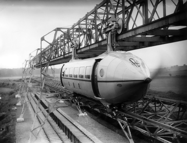
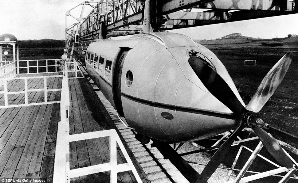
Also in the early 1920s, fellow German engineers Kurt Wiesinger and Franz Friedrich Kruckenberg had similar ideas of using propellers to improve and quicken rail traffic. Wiesinger envisioned propelling railcars along the tracks with propellers, while Kruckenberg was considering a streamlined, propeller-driven gondola suspended from a single overhead track as a Zeppelin-on-rails. Kruckenberg’s design was similar to George Bennie’s Railplane of the same period. The pair met in 1923 but soon had a falling out and went their separate ways.

Kruckenberg had studied shipbuilding at the Technical University in Danzig (now Gdańsk University of Technology). One of his professors, Johann Schütte, had partnered with industrialist Karl Lanz to form Luftschiffbau Schütte-Lanz (Airship Construction Schütte-Lanz) in April 1909. After his graduation in August 1909, Kruckenberg joined the firm as a developmental engineer. Kruckenberg was involved with both airship and aircraft constructions while working at Schütte-Lanz, and he was the firm’s chief designer and director of aircraft production during World War I.

After World War I, Kruckenberg left Schütte-Lanz and began to focus on ways to improve rail travel, which is when he met Wiesinger. In July 1924, Kruckenberg partnered with Curt Stedefeld, an associate from university who had also worked for Schütte-Lanz and had founded the Company for Traffic Engineering (Gesellschaft für Verkehrstechnik, GVT) to promote the overhead rail system. Despite a forecasted top speed of 224 mph (360 km/h), the German Ministry of Transportation (Reichsverkehrsministerium) and the German State Railroad Company (Deutschen Reichsbahn-Gesellschaft, DRG) were not willing to offer any financial support. The main objection was the cost of the overhead rail system, which required the support and construction of a completely new infrastructure.

DVL-Propellerwagen

The DVL’s Propellerwagen was strictly a test machine and not intended to transport passengers. However, the Propellerwagen provided important information on suspension and handling that was applied to the Rail Zeppelin.

In April 1928, Kruckenberg and Stedefeld founded the Railplane Company (Flugbahn-Gesellschaft, FG) in Heidelberg. The purpose of the new company was to build a propeller-driven railcar for experimentation on existing rail lines to validate the concepts of the overhead rail system. Once FG had demonstrated reliable performance on existing rails, it was hoped that the DRG would be willing to support the overhead rail system.

Around the same time, the DVL was interested in constructing a Propellerwagen to revive the testing of engines and propellers on railcars. Both FG and DVL had petitioned the DRG for the use of a straight, 5-mile (8-km) long, unused track between Langenhagen and Celle. The DRG proposed that the FG and the DVL work together to build a test rig that could be used to test engines and propellers and validate the concepts of propeller-driven railcars.

The DVL Propellerwagen test railcar was completely enclosed with an engine and propeller at each end. The narrow machine was tall with flat sides and had two axles. The rear engine drove its propeller directly via a long shaft, while the front engine drove an elevated propeller shaft via a wide belt. Both engines were six-cylinder, inline BMW IVs that produced 250 hp (186 kW) at 1,400 rpm. The test car weighed around 30,865 lb (14,000 kg) and had a top speed of 109 mph (175 km/h). After operating under its own power for the first time in April 1929, the test railcar eventually made 82 runs that totaled approximately 620 miles (1,000 km). While the DVL test machine did not help advance GVT/BG’s study of aerodynamics, it did provide important information about suspension, handling, and the operation of a propeller-driven railcar.

Rail-Zeppelin-no-body-30-08-1930

The bodyless Rail Zeppelin on 30 August 1930 illustrating the machine’s intricate frame. Note the numerous lightening holes in the truss frame. The engine-driven centrifugal fan drew in air via the circular opening (one on each side). The air was then forced through the large, square radiator in the lower rear of the railcar.

With information from the RVL tests in hand, Kruckenberg and his team compared diesel-electric drives against propeller drives for their railcar. They found that the diesel-electric would cost about 19 times more than the propeller drive and would weigh around 19,842 lb (9,000 kg), compared to 772 lb (350 kg) for the propeller and engine. In June 1929, the design of a streamlined, propeller-driven Railplane Express Car (Flugbahn-Schnellwagen) was laid out and designated Propeller Railcar A (Propellertriebwagen A). This machine was undoubtedly inspired to some degree by the earlier designs of Geissen and Wiesinger. Detailed design work was done in October 1929, and wind tunnel models were tested the following month. Due to its design, construction, and appearance, the streamlined, high-speed railcar became commonly known as the Rail Zeppelin (Schienenzeppelin).

The Rail Zeppelin consisted of a steel chassis with an aluminum truss frame. The engine supports and some other components were also made of steel. The aluminum frame was perforated with extensive lightening holes. The machine was supported on two axles and had a wheelbase of 64 ft 4 in (19.60 m). The axles used rubber ball dampeners for their suspension. Each of its four wheels were 39 in (1.0 m) in diameter. The inner flange of the wheels was made taller than normal to help prevent any possible derailments caused by the machine’s anticipated high speeds. Air-powered friction brakes were used to slow the Rail Zeppelin. An electric drive motor powered the front axle for moving the machine in a limited manner up to 12.4 miles (20 km) and at relatively slow speeds.

Rail-Zeppelin-front-left

The completed Rail Zeppelin displaying its streamlined form for press photographers. Note the two exhaust stacks at the rear of the machine and its long wheelbase.

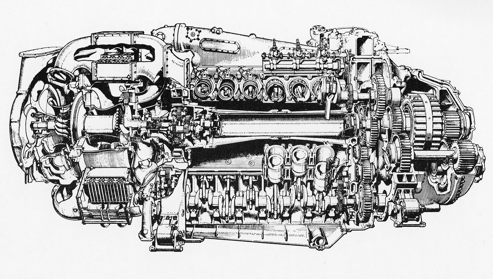
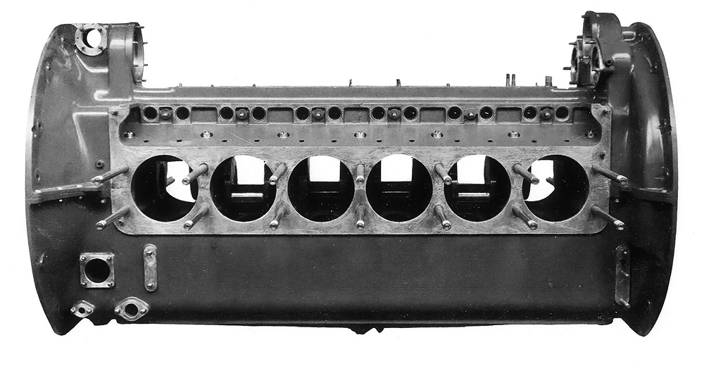
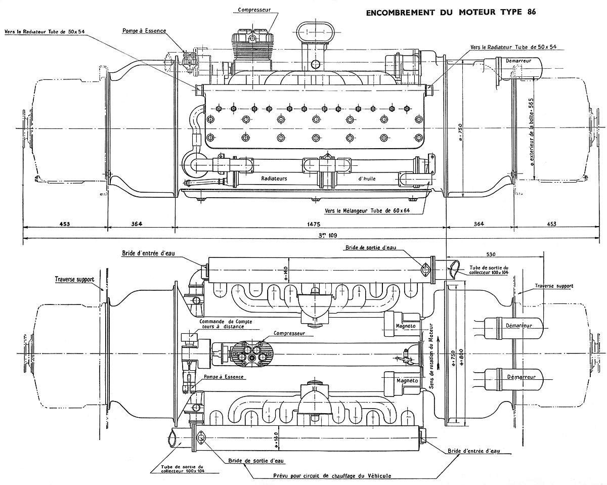
Above the rear axle was a single BMW VI liquid-cooled V-12 engine. The BMW VI had a 6.30 in (160 mm) bore and a 7.48 in (190 mm) stroke. The engine displaced 2,797 cu in (45.84 L) and produced 500 hp (373 kW) at 1,410 rpm and 600 hp (447 kW) at 1,540 rpm. The engine’s exhaust was expelled through two vertical stacks. The drive end of the engine pointed toward the rear of the Rail Zeppelin and was elevated seven degrees. A shaft, which was also angled at seven degrees, extended approximately 7 ft 7 in (2.3 m) back to the rear of the machine and turned a four-blade, fixed-pitch Heine propeller made from ash wood. The seven-degree angle on the propeller applied downward force on the Rail Zeppelin and directed the propwash up and away from people on rail platforms. The propeller was 9 ft 2 in (2.80 m) in diameter and was comprised of two stacked two-blade units.

Also attached to the drive end of the engine was a centrifugal fan that circulated cooling air through the engine compartment. Air was drawn in via vents on each side of the Rail Zeppelin and entered a duct at the center of the machine. The air then passed through radiators and was expelled out from the bottom of the Rail Zeppelin. The engine also powered the compressor for the air brakes and two generators for the electrical system. Storage batteries were located in the train’s nose.

The Rail Zeppelin was covered by a streamlined, aerodynamic body. The front, lower sides, and rear of the machine were covered by aluminum sheeting. Windows extended along the sides of the passenger compartment. Due to the expected speed of the Rail Zeppelin, none of the windows opened, and ventilation was provided by forced air. The top of the railcar was covered with fire-proof canvas.

Rail-Zeppelin-rear-four-blade-21-10-1930

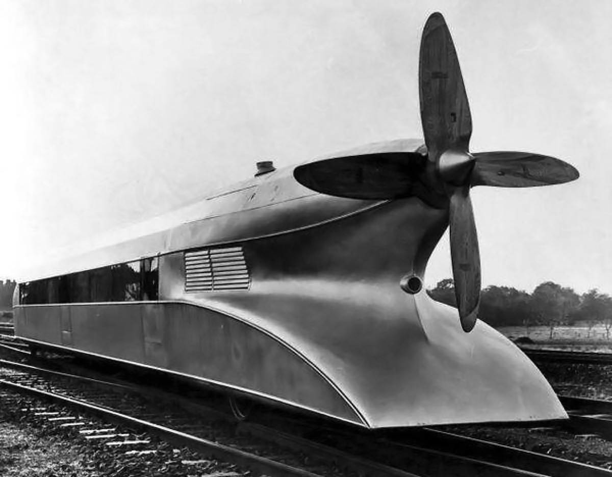
Rear view of the Rail Zeppelin with its four-blade propeller. The grate on the side was the cooling air intake. The circular housing under the propeller was for lights.

Two drivers sat side-by-side at the front of the train in a raised cockpit, which also had seats for two observers. Passenger compartment access doors were positioned at the front, middle, and rear on each side of the Rail Zeppelin. The 8 ft 2 in (2.5 m) wide and 52 ft 6 in (16 m) long passenger cabin was insulated and had wood paneling. As designed, the passenger compartment consisted of six sections, with each section accommodating four passengers, and a central aisle extended through each section. In addition to the 24-seat configuration, an alternative configuration with bench seating could accommodate 44 passengers. A lavatory was provided at the rear of the cabin. As built, only the forward three compartments were completed, and the rear three compartments held test equipment. The Rail Zeppelin was 84 ft 10 in (25.85 m) long, 8 ft 9 in (2.66 m) wide, and 9 ft 2 in (2.80 m) tall. The railcar weighed 40,962 lb (18,580 kg).

Construction of the Rail Zeppelin started in early 1930 at the DRG repair works in Leinhausen, near Hannover. Without its body, the railcar was mostly complete in August 1930 and moved under its own power with the electric motor. The body was added, and the Rail Zeppelin was completed in September. The first test with propeller power occurred on 25 September 1930. During the first high-speed test, the Rail Zeppelin reached 62 mph (100 km/h) after 66 seconds and 3,232 ft (985 m) of forward travel. The machine hit 93 mph (150 km/h) after two minutes, and the throttle was pulled back just past three minutes at 113 mph (182 km/h).

Rail-Zeppelin-two-blade-station

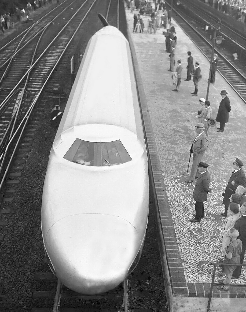
The Rail Zeppelin with its two-blade propeller sits at Spandau (Berlin) station after its run on 21 June 1931. The two-blade propeller improved the machine’s top speed but slowed acceleration.

The initial testing was done in secret and revealed that braking was an issue. Due to the Rail Zeppelin’s streamlining and relatively light weight, light breaking took a long distance, and heavy breaking had a tendency to lock the rear axle. In one instance, the brakes locked the rear axle at 112 mph (180 km/h), and it took 1.2 miles (2 km) for the railcar to come to a stop. A flat spot on the rear wheels about .14 in (3.5 mm) deep was discovered during a quick inspection, but the Rail Zeppelin was still operated up to 87 mph (140 km/h) on its return trip.

On 18 October 1930, the Rail Zeppelin was debuted to the press. Tests continued, some of which involved DRG officials. To test the concept of using a propeller with adjustable-pitch blades, a propeller with reversed pitch was installed, and the Rail Zeppelin was run backward at 37 mph (60 km/h). With the normal forward-thrust propeller reinstalled, propeller braking tests were conducted. The electric motor was used to reverse the train at 28 mph (45 km/h). Then the propeller was engaged, and it alone halted the Rail Zeppelin in 20 seconds. These tests indicated that a fully reversible pitch propeller would greatly enhance the Rail Zeppelin’s braking and improve its safety.

Rail-Zeppelin-top

This upper view of the Rail Zeppelin in Berlin illustrates the machine’s canvas covering over its upper body. Note the windshield wipers and the two-blade propeller.

Testing on the isolated track continued until May 1931, when the Rail Zeppelin was operated on the main line. However, no German insurance company would cover the propeller-driven train, and arrangements had to be made with Lloyd’s of London for coverage. The main line test was a 12.2-mile (19.7-km) stretch between Plockhorst and Lehrte. The Rail Zeppelin drew quite a crowd wherever it operated, necessitating a police presence to control the spectators. On 10 May, the machine covered the distance in 10 minutes and reached a top speed of 127 mph (205 km/h).

Testing over a longer distance was needed, so the 160-mile (257-km) route between Hamburg and Berlin was selected. The four-blade propeller was switched in favor of a two-blade unit that would provide a higher top speed at the cost of acceleration. The two-blade propeller was of the same construction as the previous propeller—fixed pitch, wood, and 9 ft 2 in (2.80 m) in diameter.

On 21 June 1931, the Rail Zeppelin left the Hamburg-Bergedorf station at 3:27 AM with a number of observers and crew on board. As the train traveled, its speed continued to increase. However, the track speed limit around many of the curves was 62 mph (100 km/h), which caused the Rail Zeppelin to slow often and accelerate on the straight stretches. Over the 7.5 miles (12-km) separating Karstädt and Dergenthin, the Rail Zeppelin averaged 143.0 mph (230.2 km/h)—a new speed record for passenger rail travel that would stand until 1954. The train arrived in Berlin at 5:05 AM with an average speed of 97.7 mph (157.3 km/h). Along the way, the Rail Zeppelin burned only 48.6 US gal (40.5 Imp gal / 184 L) of fuel, which averaged to 3.3 miles per US gal (1.4 km/L).

Rail-Zeppelin-four-blade-station

With its propeller spinning, the Rail Zeppelin awaits departure at a station. Although the propeller did not really extend beyond the railcar’s body, this view illustrates the rather disconcerting proposition of passengers coming into close proximity of the large propeller. Note the open middle access door.

After its record run, the Rail Zeppelin was put on display at the Rennbahn-Stadion (now Olympiastadion) railway station in Berlin until 25 June 1930. After the display, the train embarked on a short tour of Germany. The four-blade propeller was reinstalled for the tour, and the speed was kept down to conform with normal scheduled traffic on the line. Once again, the Rail Zeppelin drew large crowds wherever it went. The machine returned to Hannover on 28 June.

A new electromagnetic braking system was installed on the Rail Zeppelin and was tested in March 1932. The system was able to stop the train from 103 mph (165 km/h) in 2,067 ft (630 m). While this was a definite improvement, the distance was still longer than desired. Although the Rail Zeppelin had achieved some level of success, the practicality of such a machine was in question. The train’s long wheelbase caused issues on tight curves, and its ineffective brakes necessitated long stopping distances. The propeller-driven design did not allow coupling multiple units together, and the machine was unable to easily maneuver forward and back for short distances. The large propeller always presented a level of danger to anyone in close proximity to the Rail Zeppelin, and that included passengers waiting on rail platforms.

Rail-Zeppelin-Diesel-hydraulic

Image of the modified Rail Zeppelin with propeller removed and the engine installed in the nose. The nose and cockpit were revised for the installation of the engine and the hydraulic drive. Barely visible is the dual-axle front bogie.

Kruckenberg and his team took another look at the future of rail travel, and the propeller-driven railcar concept was discarded in favor of a diesel-hydraulic drive that was much lighter than diesel-electric. In May 1932, modifications were started on the Rail Zeppelin to convert the machine to the new power system. The BMW engine and propeller were removed from the rear, and the engine was temporarily installed in the nose of the train until the intended Maybach GO 5 was available. The GO 5 was a 2,588 cu in (42.4 L) diesel V-12 that produced 410 hp (305 kW) at 1,400 rpm. The engine’s exhaust was collected in a central duct that split the center of the cockpit’s windscreen. Via a Föttinger fluid coupling, the engine drove a double-axle bogie positioned under the cockpit. The bogie had a wheelbase of 6 ft 7 in (2.0 m). To accommodate the changes, the train’s nose was elongated, and its cockpit was raised. Its length was increased to 95 ft 2 in (29.0 m) and its weight increased to 62,832 lb (28,500 kg).

The revised Rail Zeppelin was completed in November 1932. The train was tested in early 1933 and reached 87 mph (140 km/h) in under two minutes after traveling 1.5 miles (2,426 m). It was also run at least to 99 mph (160 km/h). However, the DRG had become interested in other trains, namely those powered by diesel-electric engines. The Rail Zeppelin continued to be tested through 1934 and accumulated over 1,491 miles (2,400 km) with its new drive system. The GO 5 engine was finally installed in 1934, and the machine was sold to the DRG. It does not appear that much testing was done with the GO 5 engine. While Kruckenberg and his team continued to design more conventional locomotives throughout the 1930s, the Rail Zeppelin was placed into storage. In 1939, the Rail Zeppelin was scrapped so that its metal could be used to rebuild the German armed forces.

The Rail Zeppelin and its diesel-hydraulic drive served as the basis for the Kruckenberg-designed SVT 137 155, which could accommodate 100 passengers. A single example of the SVT 137 155 was completed in 1938, and the three-section express train set a conventional passenger train speed record on 23 June 1939 at 134 mph (215 km/h). The SVT 137 155 never entered regular service, and it was scrapped in 1967.

SVT-137-155

The SVT 137 155 built upon the Rail Zeppelin’s diesel-hydraulic experiments. Note the exhaust stack splitting the windscreen.

Sources:
Der Schienenzeppelin by Alfred Gottwaldt (2006)
BMW Aero Engines by Fred Jakobs, Robert Kroschel, and Christian Pierer (2009)
http://greyfalcon.us/FRANZ%20KRUCKENBERG%20SCHIENENZEPPELIN.htm
https://www.julianvonheyl.de/ingenieure/der_schienenzeppelin_von_franz_kruckenberg.shtml
https://interestingengineering.com/this-german-engineer-created-a-hybrid-of-a-train-and-a-zeppelin

PRR-T1-5526

Pennsylvania Railroad 4-4-4-4 T1 Locomotive

By William Pearce

In the late 1930s, Baldwin Locomotive Works (Baldwin) of Eddystone, Pennsylvania sought a partner to support the design of an experimental, rigid-frame, duplex, 4-4-4-4 locomotive. With this wheel arrangement, the engine would have a four-wheel leading truck, two independent sets of four-wheel drivers, and a four-wheel trailing truck. As a duplex engine, each of the four-wheel drivers would be powered by a pair of separate cylinders. Baldwin’s Chief Engineer Ralph P. Johnson believed the newly designed engine would be capable of improved efficiency that would rival diesel locomotives, which were just beginning to outperform steam. Compared to an articulated locomotive, a rigid-frame duplex arrangement created a comparatively light engine well-suited for high speeds. In addition, having four smaller cylinders with a reduced piston speed decreased wear and maintenance compared to two larger, harder-working cylinders as used in a standard locomotive layout, such as a 4-8-4. If not well-balanced, the reciprocating and revolving forces of the drive wheels on powerful two-cylinder locomotives could actually damage the track, an issue that was alleviated with a four-cylinder duplex.

PRR-T1-6110

The T1 prototype, engine No. 6110, shortly after its completion by Baldwin in April 1942. The taper for the pointed nose extended much farther back than on the production engines. The front of the locomotive was enclosed with skirting, and casings extended the length of the engine, covering the top of the drive wheels. Note the gold accents and lettering.

Baldwin had just collaborated with the Pennsylvania Railroad (PRR) in creating the S1, which was finished in January 1939. The S1 was an experimental, rigid-frame, duplex locomotive with a 6-4-4-6 wheel arrangement. Designed to haul a 1,200-ton (1,089-t) passenger train at 100 mph (161 km/h), the very long S1 was PRR’s experimental trial with a duplex locomotive, and the company was interested in Baldwin’s new design. On 26 June 1940, PRR ordered two prototypes of Baldwin’s engine, but specified that it needed to use poppet valves and that the second prototype would be fitted with a booster engine on its trailing truck. PRR designated the prototype engines as the T1 class, and gave them engine numbers 6110 and 6111. Incidentally, the T1 prototypes were ordered before the S1 had entered regular service.

Starting in 1938, PRR had been experimenting with poppet valves in an effort to improve efficiency and increase power compared to the typical piston spool valve. In a standard Walschaerts valve gear, a piston spool valve was mounted in a valve chest above the double-acting cylinder. The spool valve slid back and forth, allowing steam to enter one side of the double-acting cylinder while simultaneously opening the other side to exhaust the previous steam charge. The steam flowed from the center of the valve chest into the front of the cylinder, pushing the piston back to the rear of the cylinder. The valve then slid rearward to direct steam into the rear part of the cylinder and allow the front part of the cylinder to exhaust. Steam entering the rear part of the cylinder pushed the piston forward, returning it to its original position. The efficiency of the design was limited since the admission and exhaust were both controlled by the single piston spool valve.

Prr-T1-cab

A glimpse inside of the cab of No. 6110 reveals the complex and utilitarian controls of even the most advanced steam engine. Image the heat, wind, soot, vibration, and sound of the locomotive under full steam at 100 mph (161 km/h).

With the Type A poppet valve system made by Franklin Railway Services Inc (Franklin), separate intake (admission) and exhaust valves opened to respectively allow the fresh steam charge into the cylinder and expel the spent charge after it acted on the piston. The head of these valves resembled a spoked wheel, the “hub” of which was mounted to the valve stem. When closed, the upper and lower rims of the head sealed against two separate seats. When open, steam flowed around the head and also flowed nearly unobstructed through the “spoked wheel” center of the head. The poppet admission and exhaust valves on the locomotive were independently controlled, allowing for different timing of when the valves opened and different durations of how long the valves were open. This flexibility enabled the most efficient flow of steam throughout all the various speeds the engine was traveling. PRR had installed poppet valves on a 4-6-2 K4 (No. 5399) locomotive and recorded an increase in power while operating at 80 mph (129 km/h) and above of over 40 percent.

The PRR T1 was a duplex locomotive that utilized a 4-4-4-4 wheel arrangement and was designed to haul 880 trailing tons (798-t) at 100 mph (161 km/h). PRR envisioned using the engines to haul express passenger trains on the 713-mile (1,147-km) route between Harrisburg, Pennsylvania and Chicago, Illinois. PRR anticipated that the T1 would replace its aging fleet of K4 engines.

The T1 used a four-wheel leading truck with 36 in (.91 m) wheels positioned at the front of the engine under the smokebox. A set of four 80 in (2.03 m) drive wheels followed, trailed by another nearly-identical set of four drive wheels. A four-wheel trailing truck with 42 in (1.07 m) wheels was positioned at the rear of the engine under the cab. To aid traction, sand carried in sand boxes could be deposited on the rails just ahead of the front drive wheels of each set. The two trucks and two sets of drive wheels were mounted in roller bearings to a single-piece frame bed made of cast steel by General Steel Castings in St Louis, Missouri. The cylinders and their valve chests were integrally cast with the frame, which was over 60 ft (18.29 m) long.

PRR-T1-6111

The second T1 prototype, No. 6111, displaying its unique styling done by Raymond Loewy. This engine was equipped with a booster engine, which was not included on any of the production locomotives.

The T1 was made up of a 68 ft 2.5 in (20.79 m) long engine and a 53 ft 9.5 in (16.40 m) long tender that carried the locomotive’s coal and water. This gave the complete engine an overall length of 122 ft 10 in (37.43 m). The Class 180 P 76 tender was supported by two eight-wheel trucks with 36 in (.91 m) wheels. It carried 82,000 lb (37,195 kg) of coal in a front compartment and 19,500 gallons (73,816 L) of water in a rear compartment. When combined with the 497,200 lb (225,526 kg) engine, the 433,000 lb (196,406 kg) tender gave the T1 a total weight of 930,200 lb (421,932 kg). The locomotive was 15 ft 6 in (4.72 m) tall and 11 ft 1 in (3.38 m) wide.

An HT type mechanical stoker auger transported coal from the tender to the engine’s firebox. The firebox was 138 in (3.51 m) long and 96 in (2.44 m) wide. Coal was burned in the firebox at around 2,000 °F (1,093 °C). Heat from the firebox flowed through the boiler via 184 tubes that were 2.25 in (57.2 mm) in diameter and 69 flues that were 5.5 in (139.7 mm) in diameter. Each of the tubes and flues was 18 ft (5.50 m) long. The 253 tubes and flues would stretch for 4,554 ft (1,388 m) if laid end to end. The boiler was made from approximately 1 in (254 mm) thick nickel steel. After passing through the tubes, the soot, embers, smoke, and heat from the burning coal flowed into a smokebox at the front of the engine and was subsequently vented into the atmosphere via dual vertical stacks that were approximately 20 in (508 mm) in diameter. Spent steam from the cylinders was directed through the smokebox and helped create the draft that drew air into the firebox, through the tubes, and out the stacks.

PRR-T1-5518-org

Altoona-built No. 5518 looking fairly fresh from the factory with its original front and skirting. The styled skirting was a holdover from the prototypes and was later removed to facilitate maintenance.

The tubes, flues, and firebox of the T1 had a combined evaporative surface area of 4,218 sq ft (391.9 sq m). Heat radiating from these surfaces turned water in the boiler to steam and built up a working pressure of 300 psi (20.7 bar). With a temperature of over 420 °F (215 °C), the wet, saturated steam was collected from a steam dome above the boiler. The steam then flowed to the Type A superheater, which had a surface area of 1,430 sq ft (132.8 sq m). From the superheater, small superheater elements (tubes) took the wet steam back into the flues. The steam inside the superheater elements was heated well above its saturation value and converted to dry, superheated steam. The superheater elements delivered the dry steam to the steam chamber in the superheater.

Mounted horizontally in a steam chest above each end of each cylinder were two 5.0 in (127 mm) admission valves and two 6.0 (152 mm) in exhaust valves, giving the T1 32 valves in total. All the valves for each cylinder were controlled by an oscillating camshaft mounted transversely above the center of the cylinder. The camshaft lifted the admission valve 1.0 in (25 mm) and the exhaust valve 1.25 in (32 mm). The admission valves allowed steam to enter the front side of the double-acting cylinder and fill its 7,965 cu in (130.5 L) volume, pushing the 19.75 in (558.8 mm) diameter piston back 26 in (660.4 mm) to the rear of the cylinder. The exhaust valves at the front of the cylinder opened to let out the spent charge while the admission valves at the rear of the cylinder let in a fresh charge. The steam then pushed the piston forward to its original position. The cylinder had a smaller return volume of 7,557 cu in (123.8 L) because the 4.5 in (114 mm) diameter piston rod occupied some space. The piston rod extended straight back from the cylinder and was attached to the connecting rod via a crosshead. The connecting rod linked the piston rod to the rear driving wheel in the two-wheel set on each side of the engine. Here, the connecting rod was attached to the coupling rod, which connected the two driving-wheels together. The reciprocating parts for each four-wheel driving set were supported with roller bearings and weighed 1,992 lb (904 kg). An 88-point forced lubrication system was included to keep the locomotive’s moving parts in good working order.

PRR-T1-5518-steps

No, 5518 later in life than the above image. The skirting at the front of the engine has been removed, and stairs have replaced the foot and hand holds. The number plate keystone was moved from the front grille to under the headlight, and a new light was added to the grille. Note the shape of the valve chests above the cylinders. The two admission valves were positioned above, and were flanked by, the exhaust valves.

The T1 engine developed around 6,550 indicated hp (4,884 kW) at 85 mph (137 km/h), with a maximum recorded output of 6,665 hp (4,970 kW). The engine had a maximum tractive effort of some 64,650 lbf (287.58 kN) based on an 85 percent efficiency factor. Without any slip, each rotation of the drive wheels moved the engine 20 ft 11 in (6.38 m). At 100 mph (161 km/h), each drive wheel rotated 420 times a minute, and each double-acting piston made 840 strokes. This resulted in roughly 15,091 cu ft (427.33 cu m) of steam passing through the T1’s four cylinders every minute.

The Franklin booster engine fitted to engine No 6111, the second prototype, consisted of two steam-operated cylinders that powered the trailing truck’s rear wheels. The unit was mounted to the rear of the trailing truck and was typically used to help start the locomotive from a standstill, assist with low-speed operation, and provide additional power up grades. The booster engine added 11,200 lb (5,080 kg) to the locomotive’s weight but provided an additional 13,500 lbf (60.05 kN) of tractive effort.

The exterior of the T1 was styled by industrial designer Raymond Loewy. Cladding encased the locomotive and tapered to a wedge at the front of the engine. Casings that concealed the top of the driving wheels covered the sides of the engine. The locomotive was finished in a dark Brunswick green (Dark Green Locomotive Enamel) with gold accents and lettering. Engine No. 6110 was completed in April 1942 with 6111 following in May. The T1 prototypes underwent a series of tests, one of which measured the engine’s machine efficiency at 93 percent, and another indicating more than 6,000 hp (4,474 kW) for all speeds above 55 mph (89 km/h). After successfully passing the tests, PRR pressed the engines into service, but only on a limited basis. The engines had no trouble averaging more than 100 mph (161 km/h) over portions of their route between Harrisburg and Chicago. By April 1944, No. 6110 had accumulated 120,000 miles (193,121 km), but 6111 had traveled less. No. 6110 could produce 4,100 drawbar hp (3,057 kW) at 100 mph (161 km/h) and outperform a 5,400 total hp (4,027 kW) four-unit diesel at all speeds above 26 mph (42 km/h). However, that was just performance and did not consider maintenance or crew costs.

PRR-T1-5526

Just completed by Baldwin, No. 5526’s nearly black Brunswick green paint shines on a bright day in November 1945.

The PRR was sufficiently impressed by the T1’s performance that they ordered 50 examples in February 1945. Production was split evenly between Baldwin and PRR’s Juniata Locomotive Shops in Altoona, Pennsylvania. Engine number assignments were 5500–5524 for Altoona and 5525–5549 for Baldwin. The production version of the T1 had a flatter prow and shorter casings that exposed the drive wheels. As production continued, the casing was trimmed back farther, and the locomotive’s nose was made more utilitarian, with stairs replacing the hand and foot grips. The suspension was revised on the production T1s in an attempt to reduce the engine’s proclivity for wheel slip. At 502,200 lb (227,794 kg), the production T1 weighed an additional 5,000 lb (2,268 kg). Production T1s were not fitted with a booster engine, which cut 15 in (381 mm) off the engine’s length, reducing it to 66 ft 11.5 in (20.41 m). However, the tender gained 15 in (381 mm), making it 55 ft .5 in (16.78 m) long and leaving the T1’s overall length unchanged. Altoona was responsible for manufacturing all 50 tenders. The tender was modified as the Class 180 P 84, carrying an additional 3,200 lb (1,451 kg) of coal with a 300-gallon (1,136-L) reduction of water. The tender’s total weight increased by 9,500 lb (4,309 kg) to 442,500 lb (200,715 kg). Combined with the heavier engine, the production T1’s total weight was 944,700 lb (428,509 kg).

Altoona and Baldwin both finished their first production T1s in November 1945. Altoona completed eight of the engines by the end of the year, and Baldwin built five. The remaining 37 engines, 17 from Altoona and 20 from Baldwin, were delivered in 1946. The last Altoona-built T1, No. 5524, was completed in June 1946, and it ended up as the last steam locomotive built at the works. The last Baldwin T1 was delivered in August 1946. Each engine, without its tender, cost around $250,000.

When the T1 was running well, it was fast and smooth. The engine was a free steamer—it could run full throttle and maintain boiler pressure, but it also ran dirty. In service, the locomotive quickly covered itself with soot and grime. The T1 had no issues operating above 100 mph (161 km/h), and one engine pulled 1,150 tons (1,043-t) at that speed. However, with the T1 now in service, its tendency toward wheel slip became more of an issue. Wheel slip was encountered with the prototypes, but the situation was apparently much worse with numerous T1 engines in service. More than likely, the prototypes were carefully operated by more-experienced crews, which minimized any tendency for wheel slip. However, wheel slip was a regular occurrence with the production engines operated in normal service by crews transitioning from the forgiving K4. Some T1s were modified to deposit sand in front of all drive wheels in an effort to minimize wheel slip. Skilled engineers avoided slip with the application of sand and smooth, careful throttle movements until the locomotive was above 25 mph (40 km/h).

PRR-T1-5526-BLW

Another image of No, 5526 in front of the Baldwin works. Compared to the prototype T1s, the nose of the production engines was more blunt with less taper, and much of the side casing was omitted.

The worst wheel slip was encountered at speed when the engine would pass over some type of irregularity on the track, including moisture. The front set of drivers would slip, then catch. As soon as they caught, the rear set would slip, and then catch. This would create an imbalance and cause the front drivers to slip again, repeating the whole process. At 80 mph (129 km/h), the slip was very unsettling, and the crew had to cut power and reduce speed to stop the oscillating front-rear driver slippage. Suspension changes helped tame the T1’s wheel slip at higher speeds.

The wheel slip could also damage or break the engine’s poppet valves. Maintenance and repair of the valves and their control and drive boxes proved to be very difficult. Much of the drive system was inaccessible unless the engine was over a maintenance pit. Beyond the wheel slip, the valves began to fail in an unpredictable manner. Franklin had guaranteed the valves for continuous operation at 100 mph (161 km/h) and short bursts up to 125 mph (201 km/h). After inspecting every valve and scrutinizing numerous maintenance records, Franklin was no closer to discovering what was causing the failures. However, the majority of the valve failures occurred over a high-speed section of rail between Crestline, Ohio and Fort Wayne, Indiana. Franklin sent an observer to secretly ride the route for a month and document the train’s activity. The observer’s log detailed some remarkable findings; the T1s were often operated in excess of 130 mph (209 km/h) to make up time. One train was clocked at 142 mph (229 km/h) over several miles. Even if this one calculation was done in error, the numerous times the T1 was calculated at over 130 mph (209 km/h) could not all be mistakes. The speedometer in the cab of the locomotive stopped at 120 mph (193 km/h).

PRR-T1-5533

Baldwin-built No. 5533 was delivered in January 1946. As seen in this manufacturer photo, it lacks the polish applied to No. 5526 two months previous. Note that the front cylinder’s piston rod was much longer than that of the rear cylinder.

Franklin management decided the best course of action was to not inform PRR that their engineers were regularly overspeeding the trains and operating them beyond the guaranteed limits of the valves. Rather, the company decided to find a better metal that would allow the valves to endure the higher speeds and would also make the valve immune to damage from wheel slip. Franklin management felt that a more material would better serve any railroad interested in utilizing poppet valves. Although various materials were evaluated and numerous valve redesigns were considered, no solution was found. The Franklin poppet valves were simply prone to failure above 130 mph (209 km/h).

In fall 1946, T1 engine Nos. 5511 and 5539 were loaned to the Chesapeake & Ohio Railway (C&O) for trials. While C&O ultimately did not purchase any of the engines, they noted that the T1 handled well, particularly at higher speeds, and was able to make up time between stops. Most interesting, C&O did not feel that the T1 had any excessive tendency toward wheel slip.

In 1947, engine No. 6111 had its cylinders lined, which reduced the bore by 1.0 in (25 mm) to 18.75 in (476 mm). The modification was done to reduce the engine’s tractive effort and subsequently reduce wheel slippage. Seven or eight additional T1s were later modified with the cylinder liners. Also in 1947, PRR reported a net loss for the 1946 year, which was the first time in the company’s history that it did not turn a profit.

PRR-T1-5534

No. 5534 seen early in its career with the original front. However, the engine has a good layer of soot and dirt. Note that the tender is not marked.

In early 1948, PRR was actively converting its locomotive fleet to diesel power. In July 1948, T1 No. 5550 was fitted with Franklin Type B rotary cam valves. This change was done solely as an experiment to test the Type B unit, which was simpler and easier to maintain than the original Type A oscillating cam system. This experiment was not meant to solve the issues of valves breaking, and no other T1s were modified with the Type B unit.

In July 1949, engine No. 5547 had its Franklin Type A oscillating cam poppet valves replaced with a conventional Walschaerts valve gear. The engine was subsequently reclassified as T1a, but it was too little, too late for the T1 and PRR’s steam engines. By the end of 1949, most of the T1s had been withdrawn from service, with all of them being dropped from PRR’s roster by the end of 1953. Scrapping of the engines began in 1951, with the last T1 going under the torch in 1956. While the T1 was in standard service, engines regularly racked up over 8,000 miles (12,875 km) per month. However, steam locomotives could not match the reliability of diesel engines or their comparatively low maintenance and crew costs.

In 2013, the Pennsylvania Railroad T1 Steam Locomotive Trust (T1 Trust) was founded to build a new PRR T1 locomotive, No. 5550. Since its inception up to mid-2020, the T1 Trust has acquired or completed 34 percent of the new engine and its tender and has numerous other parts and components on order. It is the intention of the T1 Trust to complete No. 5550 by 2030 and to make the engine available for special excursion service. The T1 Trust also hopes to use No. 5550 for an attempt to break the world land speed record for a steam locomotive, which was set by the British LNER (London and North Eastern Railway) Class A4 4468 Mallard at 125.88 mph (202.58 km/h) on 3 July 1938.

PRR-T1-5528

An incredibly dirty engine No. 5528 sits unused in a railyard covered with soot and grime. The T1 was known to run dirty, but this engine appears to be neglected. Note the rolling stock positioned on the track immediately before the T1 and that wedges are jammed behind the engine’s rear set of drive wheels. Being cut up for scrap was the unglamorous end for all 52 T1 locomotives.

Sources:
Loco Profile 24: Pennsylvania Duplexii by Brian Reed (June 1972)
Pennsy Power: Steam and Electric Locomotives of the Pennsylvania Railroad, 1900-1957 by Alvin F. Staufer (1962)
American Steam Locomotives: Design and Development, 1880–1960 by William L. Withuhn (2019)
https://prrt1steamlocomotivetrust.org/
http://www.steamlocomotive.com/locobase.php?country=USA&wheel=Duplex&railroad=prr
https://revivaler.com/pennsylvania-railroad-t1-t1a-duplex/
https://newbuildsteam.com/2017/05/13/qa-t1-5550/

Napier-Deltic-T18-37K-Marine-Engine

Napier Deltic Opposed-Piston Diesel Engine

By William Pearce

In 1933, the British engineering firm D. Napier & Son (Napier) acquired licenses to produce the Junkers Jumo 204 and 205 aircraft engines. Napier sought to diversify and expand its aircraft engine business, and the company felt the two-stroke, opposed-piston, diesel engines would usher in an era of safe and fuel-efficient air travel. Napier made some modifications to the Jumo engines, but the internal components were mostly unchanged. The Jumo 204 was built as the Napier Culverin (E102), and the Jumo 205 was planned as the Napier Cutlass (E103). The Culverin was first run on 24 September 1934, but the engine garnered little interest and no orders. By 1936, after only seven Culverins were made and no Cutlasses, Napier halted further work on opposed-piston diesel aircraft engines. English Electric took over Napier in November 1942.

Napier-Deltic-E130-Three-cylinder-test-engine

The Napier E130 three-cylinder test engine that validated the triangular engine arrangement. Each of the engine’s crankshafts had a flywheel on the drive end (left). The six intake chamber openings are visible on the free (non-drive) end (right). Note the vertical coolant pipes on top of the engine. (Napier/NPHT/IMechE images)

In 1944, the British Admiralty desired to increase the survivability of the Motor Torpedo Boat (MTB). One of the main issues was that MTBs used gasoline engines. Gasoline liquid is highly flammable, and gasoline vapor is highly explosive. MTB safety would be improved if a switch to diesel engines could be made. Diesel fuel has non-explosive characteristics and a much higher flashpoint than gasoline. However, at the time, there were no suitable diesel engines to power MTBs.

Around 1945, Napier and other companies submitted proposals to the Admiralty for a light-weight, powerful, and compact 18-cylinder diesel engine. Napier’s new engine carried the company designation E130, and the design was influenced by their experience with the Junkers Jumo diesel engines, their work on the Culverin and Cutlass, and analyses of other Jumo six-cylinder engines captured during World War II. However, there is no mention of the Junkers Jumo 223 contributing to Napier’s engine design. In early 1946, the Admiralty selected the Napier design and issued a developmental contract that covered the construction of one single-cylinder test engine, one three-cylinder test engine, and six prototype 18-cylinder engines.

Napier-Deltic-drive-end-section

Section drawing from the drive end of a Deltic engine. The air chamber surrounds the intake end of the cylinder, and the exhaust manifolds are mounted to the outer sides of the engine. Note the rotation of the crankshafts. (Napier/NPHT/IMechE image)

Napier’s liquid-cooled, two-stroke engine used opposed-pistons, a design feature that eliminated many parts, required no cylinder head, improved thermal efficiency, and resulted in more power for a given size and weight. In an opposed-piston engine, each cylinder has two pistons that move toward each other to form a single combustion space near the center of the cylinder. Ports in the cylinder wall that are covered and uncovered by the pistons bring in air and allow exhaust gases to escape. The most unusual aspect of Napier’s design was that the engine was formed as an inverted triangle, with a crankshaft at each corner. Because of its triangular structure, the name Deltic was selected in reference to the Greek letter Delta, and the 18-cylinder engine was known as the Deltic D18 (or just 18). The triangular design resulted in a compact engine with a very rigid structure.

Design work on the Napier Deltic started under Ben Barlow, George Murray, and Ernest Chatterton, Chief Engineer of the Piston Engine Division at Napier. The project was initially overseen by Henry Nelson, with Herbert Sammons taking over in 1949. The Deltic engine formed an equilateral triangle with each of its three cylinder banks angled at 60 degrees. Cast aluminum crankcase housings were at each corner of the triangle, with the lower crankcase incorporating an oil sump and also serving as the engine’s base. Each cast aluminum cylinder bank was sandwiched between two crankcases via through bolts. The monobloc cylinder banks were identical, as were the upper two crankcases. However, various ancillary components were installed according to the casting’s position on the complete engine.

Napier-Deltic-18-Triangle-Case

The assembled cylinder banks and crankcases of an 18-cylinder Napier Deltic engine seen from the free end. Note the open space between the cylinder banks. The stadium (oval) ports are to the air chambers. The bushings visible in the upper crankcases, at the triangle’s corners, supported the shafts that drove the blower. (Napier/NPHT/IMechE image)

The forged-steel cylinder wet liners were open-ended and had a chrome-plated bore to reduce wear. Part of the bore was etched with small dimples to retain lubricating oil and reduce piston ring wear. The liner was approximately 32 in (813 mm) long and protruded some distance into the crankcases. The ends of the liner were notched to allow clearance for the swinging connecting rods. Near one end of the liner were 14 intake ports with a tangential entry to impart a swirling motion of the incoming air. The swirling air helped scavenge the cylinder through the nine exhaust ports near the other end of the liner. In each cylinder, one piston would cover and uncover the intake ports while the other piston would do the same for the exhaust ports. The exhaust ports were uncovered (opened) 34.5 degrees before the intake ports. Both sets of ports were uncovered (open) for 101.5 degrees, and the intake ports were uncovered (open) for 5.5 degrees after the exhaust ports were covered (closed). The placement of the intake and exhaust ports at opposite ends of the cylinder liner allowed for uniflow scavenging of the cylinder. The liners were shrink-fitted into the cylinder banks and secured by an annular nut on the intake side.

The two-piece pistons consisted of a cast aluminum outer body and a forged Y-alloy (nickel-aluminum alloy) inner member that held the wrist pin. The inner member was heat-shrunk to the outer piston body and secured by a large circlip. Oil flowed between the two pieces to cool the piston. Three compression rings were positioned just below the piston crown, and two oil scraper rings were located near the bottom of the piston skirt. The pistons were attached to fork-and-blade connecting rods, with the exhaust pistons mounted to the forked rods and the intake pistons mounted to the blade rods. The opposed pistons created a compression ratio of 17.5 to 1 (some sources say 15 to 1).

Napier-Deltic-assembly

Napier Deltic engine assembly, with phasing gear housings being built up in the lower right. At left is a completed phasing gear housing; note the two idler gears connecting the lower crankshaft to the central output shaft. Toward the center are Deltics in various stages of assembly. A completed engine without its blower installed is in the upper right. Note the opening in the center of the engine. (Napier/NPHT/IMechE image)

A two-piece phasing gear housing at the drive end of the engine contained the gears that connected the crankshafts to the main output shaft. The main output shaft was usually located at the center of the engine, but different phasing gear housings allowed for different output shaft locations. Each crankshaft was coupled to its drive gear via a short, flexible quill shaft. When viewed from the free (non-drive) end of the engine, the upper two crankshafts rotated clockwise and were connected to the main output shaft via one idler gear. The lower crankshaft rotated counterclockwise and was connected to the main output shaft via two idler gears. The idler gears could be repositioned to reverse the rotation of the output shaft. Each crankshaft was supported in its crankcase by seven main bearings, and each main bearing cap was secured by four studs and two transverse bolts. The crankshafts were phased so that the exhaust piston in each cylinder led the intake piston by 20 degrees. The reverse rotation of the lower crankshaft, and the crankshaft phasing was devised by Herbert Penwarden from the Admiralty Engineering Laboratory.

Via a quill shaft and bevel gears, each crankshaft also drove a camshaft for the fuel injection pumps. The camshaft was located in a housing bolted to the outer side of each cylinder bank, near its center. Each camshaft operated six fuel injection pumps, and each pump fed fuel to two injectors per cylinder. The timing of the pumps changed depending on engine RPM. The upper two crankshafts drove separate flexible drive shafts for the blower (weak supercharger). The driveshafts were positioned at the upper, inner corners of the engine triangle. They led to the opposite end of the engine and powered a single-stage, double-sided centrifugal blower. The impeller was 15.5 in (394 mm) in diameter and rotated at 5.72 times crankshaft speed, creating 7.8 psi of boost (.53 bar). The pressurized air from the blower was fed into a chamber that extended through each cylinder bank and that surrounded the intake ports in the cylinder liner. Exhaust gases were collected via a water-cooled manifold that attached to the outer side of each cylinder bank. The lower crankshaft drove a flexible drive shaft to power the engine’s two oil and two water pumps.

Napier-Deltic-T18-37K-sections-display

Basic sections of the Deltic (T18-37K) marine engine. From left to right are the blower section (turbo-blower in this case), D18-cylinder engine section, phasing gear housing, and the bi-directional gearbox. The Deltic was a powerful diesel engine for its size and weight. (Napier/NPHT/IMechE image)

When viewing the engine from the free end, the cylinder banks were designated as follows: left was Bank A; upper, horizontal was Bank B; and right was Bank C. The crankshafts were designated as follows: upper left was Crankshaft AB, upper right was Crankshaft BC, and lower was Crankshaft CA. The cylinder rows were numbered with Bank 1 at the free end, and subsequent banks were numbered consecutively with Bank 6 at the drive end. The Deltic D18’s firing order was Bank C cylinder 1 (C1), A6, B1, C5, A1, B5, C3, A5, B3, C4, A3, B4, C2, A4, B2, C6, A2, and B6.

The Napier Deltic had a 5.125 in (130 mm) bore and a 7.25 in (184 mm) stroke (x2). This gave each cylinder a displacement of 299 cu in (4.9 L), and the 18-cylinder engine displaced 5,384 cu in (88.2 L). The bare engine (without the bi-directional marine gearbox) had a maximum, 15-minute output of 2,730 hp (2,036 kW) at 2,000 rpm with a specific fuel consumption (sfc) of .380 lb/hp/hr (231 g/kW/h). The Deltic’s continuous rating was 2,035 hp (1,517 kW) at 1,700 rpm with a sfc of .364 lb/hp/hr (221 g/kW/h). With the bi-directional gearbox, the engine produced 2,500 hp (1,864 kW) at 2,000 rpm with a sfc of .415 lb/hp/hr (252 g/kW/h) and 1,875 hp (1,398 kW) at 1,700 rpm with a sfc of .395 lb/hp/hr (240 g/kW/h). The Deltic D18 was 105 in (2.67 m) long, 71.25 in (1.81 m) wide, and 80 in (2.03 m) tall. The bi-directional gearbox added another 36 in (.91 m). The engine weighed 8,860 lb (4,018 kg) without the bi-directional gearbox and 10,500 lb (4,763 kg) with it.

The single-cylinder test engine was designed from October to December 1946, with the three-cylinder engine following from January to May 1947. Testing of these engines started as soon as construction was completed. The three-cylinder engine represented just one row of a Deltic engine, but it demonstrated the validity of the components used in the triangular arrangement.

Napier-Deltic-D18-E130-Prototype

Free end of the 2,500 hp (1,864 kW) Deltic D18-1 (E130) prototype engine. Note the two intakes, one for each side of the double-sided blower. Each cylinder bank had two, large exhaust manifolds. The transverse bolts threaded into the main bearings can be seen on the side of the upper crankcase. (Napier/NPHT/IMechE image)

The first 18-cylinder Deltic Series I engine was assembled by March 1950. The engine was soon to be tested at Napier’s works in Acton, England; however, a cable broke as the engine was being mounted to the stand. It fell on the stand, damaging the engine and the test stand. Repairs were made, and engine began testing in April 1950. The 18-cylinder Deltic fired a cylinder every 20 degrees of crankshaft rotation, which resulted in smooth, nearly-constant output torque. Engine idle was around 600 rpm, and the Deltic demonstrated a gross mechanical efficiency of 85.5% at 2,000 rpm. In late 1951, two Deltics were installed in place of the three Mercedes-Benz MB 501 V-20 engines in a former German E-boat S-212 (redesignated Fast Patrol Boat P5212). By January 1952, the originally-contracted six Deltic D18 engines had been built. In 1953, an Admiralty 1,000-hr type test was completed and indicated the engine could run 2,000 hours between overhauls.

By 1954, Napier was offering a commercial version of the Deltic D18 Series I (E169). This was basically a de-rated engine. The commercial engine produced 1,900 hp (1,417 kW) at 1,500 rpm with a sfc of .363 lb/hp/hr (221 g/kW/h) and could operate for 5,000 hours between overhauls. In addition to a variety of marine applications, Deltic engines could also run power generation sets, water pumps, and be used to power traction motors for locomotives. Napier also built a nine-cylinder version with three banks of three cylinders. The Deltic 9 (E159/E165) displaced 2,692 cu in (44.1 L) and had a one-sided centrifugal blower but was otherwise of the same construction as the Deltic D18. It fired one cylinder for every 40 degrees of crankshaft rotation. Maximum output for the Deltic 9 was 1,250 hp (932 kW) at 2,000 rpm for the high-power version and 950 hp (708 kW) at 1,500 rpm for the commercial version. By late 1955, Deltic test and production engines had accumulated over 20,000 hours of operation.

Napier-Deltic-C18-5-Compound-Marine-Engine

The 5,500 hp (4,101 kW) compound Deltic C18 (E185) engine was the most powerful piston engine Napier ever built. Although it is covered, the intake can be seen in the upper part of the phasing gear housing. Exhaust was routed through the three-stage turbine, which powered the eight-stage compressor inside the engine’s triangle. (Napier/NPHT/IMechE image)

In 1956, Napier built a compound diesel engine known as the Deltic C18 (E185). Serious development of the C18 occurred after the Napier Nomad II compound diesel aircraft engine was cancelled in 1955. The Deltic C18 had an eight-stage (some sources say 12-stage, which was the same number of stages as used in the Nomad II) axial compressor positioned inside the engine triangle. The compressor was driven by a three-stage turbine, which was powered by the engine’s exhaust gases. The turbine was positioned in the normal blower position on the free end of the engine. A new phasing gear housing was constructed with an opening that allowed air into the center of the engine triangle and served as the inlet for the compressor. The Deltic C18 produced 5,500 hp (4,101 kW) at 2,000 rpm. The engine was 124 in (3.15 m) long, 65 in (1.65 m) wide, and 77 in (1.96 m) tall. The C18 weighed approximately 10,700 lb (4,853 kg). The engine was tested in 1957, but only one experimental C18 was built. While undergoing power tests, the engine was intentionally pushed beyond its limits until a connecting rod failed at 5,600 hp (4,176 kW). The rod came through the crankcase, but the damage was never repaired due to the Navy’s increased focus on gas turbine engines.

By 1956, Napier had introduced some minor changes as the Series II Deltic engines, but one major change was the addition of a turbo-blower. These engines were known as turbo-blown, and they were designated as the Deltic T18 (E171/E239). Exhaust gases were collected and fed into an axial-flow turbine mounted behind the blower. The turbine wheel was 18.04 in (458 mm) in diameter and helped turn the blower via a geared shaft. The turbine wheel turned at .756 times the speed of the blower impeller. The blower was still driven by the upper crankshafts, but it now turned at 8.266 times crankshaft speed. The turbo-blower created 19 psi (1.31 bar) of boost. The piston was redesigned and consisted of three-pieces: a Hidural 5 (copper alloy) crown that screwed onto an aluminum skirt to form the outer body, and a Y-alloy (nickel-aluminum alloy) inner member that held the wrist pin. A third scraper ring was added to the piston skirt. The compression ratio was increased to 17.9 to 1, and the engine used one fuel injector per cylinder. The Deltic T18 had an output of 3,100 hp (2,312 kW) at 2,100 rpm and 2,400 hp (1,641 kW) at 1,800 rpm. SFC was .414 lb/hp/hr (252 g/kW/h) and .404 lb/hp/hr (246 g/kW/h) respectively. The engine was 118 in (3.00 m) long, 75 in (1.91 m) wide, and 84 in (2.13 m) tall. The T18 weighed around 13,630 lb (6,183 kg) with the bi-directional gearbox and 11,050 lb (5,012 kg) without it. The turbo-blown nine-cylinder Deltic T9 (E172/E198) produced 1,100 hp (820 kW) at 1,600 rpm.

Napier-Deltic-T18-37K-Marine-Engine

The 3,100 hp (2,312 kW) turbo-blown Deltic T18-37K (E239) engine was most widely used in Motor Torpedo Boats. Note the exhaust manifolds leading to the turbine with its large intake at the rear of the engine. The short duct connecting the blower to the upper cylinder bank is visible. (Napier/NPHT/IMechE image)

More changes were incorporated into the Series III engines, which also introduced charge-cooling with the Deltic CT18 (E263) in 1966. For the CT18, a single drive shaft passed through the center of the engine to deliver power from the phasing gear housing to the turbo-blower. The shaft turned at 5.16 times crankshaft speed, and both the blower impeller and turbine wheel were mounted to the drive shaft. The single-sided blower impeller was relocated to behind the turbine wheel. A water-filled aftercooler was mounted before each opening of the engine’s three air compartments. The aftercooler dropped the charge temperature from 259° F (126° C) to 144° F (62°C). Pistons were again redesigned, with the Hidural 5 (copper alloy) crown bolting to the aluminum skirt. For the Deltic CT18, power increased to 3,700 hp (2,759 kw) at 2,100 rpm with a sfc of .403 lb/hp/hr (245 g/kW/h) and 2,750 hp (2,051 kW) at 1,800 rpm with a sfc of .395 lb/hp/hr (240 g/kW/h). By 1968, further development had increased the output to 4,000 hp (2,983 kW) at 2,100 rpm with a sfc of .401 lb/hp/hr (244 g/kW/h) and 3,000 hp (2,237 kW) at 1,800 rpm with a sfc of .399 lb/hp/hr (243 g/kW/h). The CT18 weighed 15,382 lb (6,977 kg) with its bi-directional gearbox.

As Napier declined in the late 1960s, English Electric moved Deltic production to the newly acquired Paxman Engine Division. The General Electric Company (GEC, not related to the US company General Electric / GE) purchased English Electric in 1968. What was once Napier basically closed in 1969. In 1975, GEC reformed Paxman Engine Division as Paxman Diesels Limited. Paxman continued to support Deltic engines, developing the CT18 to 4,140 hp (3,087 kW) in 1978 and reworking the mechanically-blown Deltic 9 for production as the D9-59K (E280) in the early 1980s. The D9-59K was constructed almost entirely with non-ferrous (non-magnetic) parts for mine-sweeper duties. In 2000, MAN acquired what used to be Paxman, and Rolls-Royce was awarded a contract to support Deltic engines in 2001. The contract was carried through until 2012, but it is not clear if the contract was extended beyond that year.

Napier-Deltic-CT18-42K-Charge-Cooled-engine

A 3,700 hp (2,759 kw) charge-cooled and turbo-blown Deltic CT18-42K (E263) engine. The turbine is located between the engine and the blower. Note the large, square aftercooler in the air duct between the blower and the engine. (Napier/NPHT/IMechE image)

Deltic engines powered a number of various MTBs, including the Royal Navy’s Dark-class (18 produced). Two 3,100 hp (2,312 kW) Deltic C18 turbo-blown engines powered each Nasty-class / Tjeld-class fast patrol boat (total of 49 built), which were designed in 1959 and put in service in 1960. These boats served with the navies of Norway, the United States, Greece, Germany, and Turkey. The boats had a top speed of 52 mph (83 km/h), and some were in service until the 1990s. Deltic engines powered Ton-class minesweepers (over 100 built) as well as the pulse generators for other minesweepers. Deltics were still being installed in new military boats during the 1980s, with the 1,180 hp (880 kW) Deltic T9-powered Hunt-class minesweepers (13 built) still in service. A few commercial vessels were also powered by Deltic engines—the largest installation was four 1,850 hp (1,380 kW) engines for the 513.5-ft (156.5-m) ore carrier Bahama King in 1958.

In 1955, two 1,650 hp (1,230 kW) Deltic D18-12 (E158) engines were used in the English Electric DP1, a prototype diesel-electric locomotive. The engines powered six English Electric EE829-1A traction motors that gave the locomotive 50,000 lbf (222.4 kN) of tractive effort. The DP1 proved successful, resulting in 22 British Rail Class 55 locomotives powered by Deltic D18-25 (E169) engines being built in the early 1960s. Called Deltics, these locomotives could exceed 110 mph (177 km/h) and were in service until the early 1980s. One 1,100 hp (919 kW) Deltic T9-29 (E172) engine was used in each of the smaller British Rail Class 23 locomotives, known as Baby Deltics. The engine powered four English Electric traction motors that gave the locomotive 47,000 lbf (209.1 kN) of tractive effort. The Baby Deltics entered service in 1959, but they were not as successful as their bigger counterparts due to shorter runs and frequent stops. All Baby Deltics were withdrawn from service by 1971.

Napier-Deltic-CT18-Charge-Cooled-cutaway

Cutaway view of a Deltic CT-18 charge-cooled and turbo-blown engine. Note the shaft through the center of the engine that powered the turbo-blower from the phasing gear. (Napier/NPHT/IMechE image)

Other Deltic designs included a 735 hp (548 kW) inline six-cylinder (E164/E197) with one bank of six cylinders and a 1,420 hp (1,059 kW) 15-cylinder (E162) with three banks of five cylinders, but these engines were not built. A 24-cylinder square engine (E260) with four crankshafts and four banks of six cylinders was also designed for an output of 5,400 hp (4,027 kW). The square engine design had much more in common with the Deltic than the Jumo 223, but it was not constructed. Including the nine-cylinder version, over 600 Deltic engines were made. A number of Deltic engines survive. Some are still operational in preserved boats or locomotives, allowing the unusual roar of the triangular two-stroke Deltic to still be heard. Others engines are in various museums, and a few are privately owned.

Note: In some cases, the Napier E number is one example of the type, with additional E numbers existing for similar engines with different configurations (marine vs rail applications). Around 100 E numbers were assigned to various Deltic designs.

Napier-Deltic-T9-33-Locomotive-Rraction-Engine

A 1,250 hp (932 kW) turbo-blown nine-cylinder Deltic T9-33 (E198) under test at Napier’s factory in Acton. The engine was similar to those used in the Baby Deltic Locomotives. Note the low position of the output shaft. (Napier/NPHT/IMechE image)

Sources:
– “The Napier Deltic Diesel Engine” by Ernest Chatterton, SAE Transactions Vol 64 (1956)
Opposed Piston Engines by Jean-Pierre Pirault and Martin Flint (2010)
Course Notes on the Deltic Engine Type T18-37K by D. Napier & Son Ltd. (December 1967)
– “Development of the Napier Deltic Charge Cooled Engine” by R. P. Taylor and C. H. Davison, Proceedings of the Institution of Mechanical Engineers Vol 183 (1968–69)
By Precision Into Power by Alan Vessey (2007)
Napier Powered by Alan Vessey (1997)
https://www.ptfnasty.com/ptfDeltic.html
http://www.npht.org/deltic/4579702653

Pennsylvania Railroad 6-4-4-6 S1 Locomotive

By William Pearce

PRR S1 6100 top

The Pennsylvania Railroad S1 engine 6100 in February 1939, shortly after completion. The S1 was the longest and heaviest rigid frame reciprocating steam passenger locomotive ever built. Note the dual stacks protruding slightly above the engine’s streamlined claddin

The Pennsylvania Railroad (PRR) was founded in 1846 and headquartered in Philadelphia, Pennsylvania. In the first half of the 20th century, PRR was the largest railroad by traffic and revenue in the United States. At one time, PRR was the largest publicly traded corporation in the world, with a budget larger than that of the U.S. government and a workforce of approximately 250,000 people.

In 1937, PRR sought to design a coal-burning steam locomotive that would pull heavy passenger trains for long runs at better than 60 mph (97 km/h). Accomplishing such tasks typically required the use of two engines pulling a single train (double-heading). PRR also hoped that the performance of the new engine would match that of the new electric locomotives just then coming into service. The new steam locomotive would serve as an experimental prototype for the railroad as it worked to modernize its fleet. The new locomotive was designated as the S1 class, and PRR collaborated with the American Locomotive Company, the Baldwin Locomotive Works, and the Lima Locomotive Works in designing and building the engine. The S1 was built in PRR’s Altoona Works in Altoona, Pennsylvania during 1938. The S1 was given the Altoona serial number 4341 and the PRR number 6100.

The PRR S1 was a unique duplex locomotive that utilized a 6-4-4-6 wheel arrangement. A six-wheel leading truck with 36 in (.91 m) wheels was positioned at the front of the engine. A set of four 84 in (2.13 m) drive wheels followed, trailed by another identical set of four drive wheels. A six-wheel trailing truck with 42 in (1.07 m) wheels was positioned at the rear of the engine. What made the S1 a duplex locomotive was its use of two separate pairs of cylinders mounted to a rigid frame. Each cylinder pair drove a set of four drive wheels. The two trucks and four pairs of drive wheels were mounted to a single-piece frame bed made of cast steel by General Steel Castings in St Louis, Missouri. The cylinders and their valve chests were integrally cast with the frame. The frame was 77 ft 9.5 in (23.7 m) long, weighed 97,620 lb (44,280 kg), and was the largest locomotive bed casting ever made. However, the use of a long rigid frame meant that the engine would not be able to operate on tracks with significant curves.

PRR S1 6100 construction

The S1 under construction with its large firebox and boiler being attached to the engine’s huge cast steel frame. While mostly concealed, the single-piece frame can be seen supporting the leading and trailing truck

With an overall length of 140 ft 2.5 in (42.7 m), the S1 was the longest rigid frame reciprocating steam passenger locomotive ever built, a fact that earned it the nickname The Big Engine. The S1 was made up of an 81 ft 1.75 in (24.7 m) long engine and a 59 ft .75 in (18.0 m) long tender that carried the locomotive’s coal and water. The engine weighed 608,170 lb (275,862 kg), and its weight was distributed with 135,100 lb (61,280 kg) on the leading truck, 191,630 lb (86,922 kg) on the trailing truck (326,730 lb / 148,202 kg total on the trucks), and 281,440 lb (127,659 kg) on the driving wheels. This distribution meant that less than half (46.28%) of the engine’s weight was on the driving wheels, a configuration that often led to wheel slip.

The tender was supported by two eight-wheel trucks with 36 in (.91 m) wheels. It carried 53,000 lb (24,040 kg) of coal in a front compartment and 24,230 gallons (91,720 L) of water in a rear compartment. When combined with the engine, the 451,840 lb (204,951 kg) tender gave the S1 a total weight of 1,060,010 lb (480,813 kg). The locomotive was 15 ft 6 in (4.7 m) tall and 10 ft 7 in (3.2 m) wide.

PRR S1 6100 NY Fair

The S1 atop its special display stand at the 1939 New York World’s Fair. The stand enabled the engine to operate daily at up to 60 mph (97 km/h). Note that the tender is painted as “American Railroads.”

An HT type mechanical stoker auger transported coal from the tender to the engine’s firebox. The firebox was 198 in (5.03 m) long and 96 in (2.44 m) wide. Coal was burned in the firebox at around 2,000 °F (1,093 °C). Heat from the firebox flowed through the boiler via 219 tubes that were 2.25 in (57.2 mm) in diameter and 69 flues that were 5.5 in (139.7 mm) in diameter. Each of the tubes and flues was 22 ft (6.7 m) long. The 288 tubes and flues would stretch for 6,336 ft (1,931 m) if laid end to end. The boiler was made from approximately 1 in (254 mm) thick nickel steel. After passing through the tubes, the soot, embers, smoke, and heat from the burning coal flowed into a smokebox at the front of the engine and was subsequently vented into the atmosphere via dual vertical stacks. Spent steam from the cylinders was directed through the smokebox and helped create the draft that drew air into the firebox, through the tubes, and out the stacks. The stacks were approximately 21 in (533 mm) in diameter and protruded 4.875 in (124 mm) above the top of the engine.

The tubes, flues, and firebox of the S1 had a combined evaporative surface area of 5,661 sq ft (525.9 sq m). Heat radiating from these surfaces turned water in the boiler to steam and built up a working pressure of 300 psi (20.7 bar). With a temperature of over 420 °F (215 °C), the wet, saturated steam was collected from slots along the top of a pipe inside the boiler shell. The steam then flowed to the modified Type A superheater, which had a surface area of 2,085 sq ft (193.7 sq m). From the superheater, 69 small superheater elements (tubes) took the wet steam back into the flues. The steam inside the superheater elements was heated well above its saturation value and converted to dry, superheated steam. The superheater elements delivered the dry steam to the steam chamber in the superheater.

PRR S1 6100 Raymond Loewy

Raymond Lowey proudly poses with the S1 at the 1939 New York World’s Fair. The engine is mounted on its display stand, and a roller can be seen under the front drive wheel.

The flow of steam in and out of each of the engine’s four cylinders was controlled by a Walschaerts valve gear. A 12 in (305 mm) diameter piston spool valve was mounted in a valve chest above each cylinder. The steam-distribution valve slid back and forth 7.5 inches (191 mm) to allow steam to enter one side of the double-acting cylinder while simultaneously opening the other side to exhaust the previous steam charge. The steam flowed from the center of the valve chest into the front of the cylinder and filled its 9,883 cu in (162 L) volume, pushing the 22 in (558.8 mm) diameter piston back 26 in (660.4 mm) to the rear of the cylinder. The valve then slid rearward to direct steam into the rear part of the cylinder and allow the front part of the cylinder to exhaust. Steam entering the rear part of the cylinder pushed the piston forward to its original position. The cylinder had a smaller return volume of approximately 9,321 cu in (153 L) on account of the 5.25 in (133 mm) diameter piston rod taking up some room. The piston rod extended straight back from the cylinder and was attached to the connecting rod via a crosshead. The connecting rod linked the piston rod to the rear driving wheel in the two-wheel set on each side of the engine. Here, the connecting rod was attached to the coupling rod, which connected the two driving-wheel sets together. The reciprocating parts for each of the four two-wheel driving sets weighed 1,010 lb (458 kg). To aid traction, sand could be deposited on the rails in front of all four front drive wheels and in front of the last pair of rear drive wheels. Two sand boxes were positioned on each side of the engine.

The S1 was designed to haul a 1,200-ton (1,089-t) passenger train at 100 mph (161 km/h). The engine developed around 6,500 indicated hp (4,847 kW) at 100 mph (161 km/h) and had a maximum tractive effort of some 76,400 lbf (339.8 kN) based on an 85% efficiency factor. Without any slip, each rotation of the drive wheels moved the engine 22 ft (6.7 m). At 100 mph (161 km/h), each drive wheel rotated 400 times a minute, and each double-acting piston made 800 strokes. This resulted in roughly 17,781 cu ft (503.5 cu m) of steam passing through the S1’s four cylinders every minute.

PRR S1 6100 Englewood snow

Early in its life, the S1 heads east from Englewood Union Station as the “Manhattan Limited.” The nameplate at the front of the engine says “Manhattan.” Note that all of the engine’s skirting and paneling is in place.

The S1 was encased in Art Deco-styled cladding designed by Raymond Loewy. The streamlined cladding consisted of aluminum panels that covered the boiler and extended to a bullet-shaped nose at the front of the engine. Skirt panels covered the lower part of the engine and partially concealed the running gear. The cladding was adorned with chrome handrails and trim accents. The S1’s low-profile stacks were concealed in a fairing atop the engine. Loewy had worked with PRR when he designed the streamlined cladding for the K4 engine 3768 in 1936. Additional K4 engines were streamlined, but not to the extent of 3768. Loewy’s S1 styling was a direct development of his work on engine 3768. It is often claimed that Loewy was awarded US patent 2,128,490 for his S1 design, but this patent was applied for on 17 July 1936 and actually details his work on the K4 engine 3768.

Completed on 31 January 1939, the S1 cost PRR approximately $669,780 USD to build, which is equivalent to $11,912,085 USD in 2018. After undergoing some initial testing, the S1 was showcased at the 1939 World’s Fair held at Flushing Meadows Corona Park on Long Island, New York from 30 April 1939 to 27 October 1940. The entire railroad display was sponsored by 27 railroads from the eastern United States. Still numbered as 6100, the S1 was branded “American Railroads” rather than the “Pennsylvania” it wore later in life. The S1 sat atop a special stand that enabled the locomotive to be operated at speed under its own power. In the stand, the engine’s drive wheels powered generators. Electricity created by the generators was used to power motors that turned the 12 wheels of the leading and trailing trucks and the 16 wheels on the tender. The drive system in the stand was configured so that all wheels turned at the same rpm. While the display was open during the 16-month fair, the S1 was operated daily from 12:00 PM to 8:00 PM at 60 mph (97 km/h). By the end of the fair, the S1 had traveled some 50,000 miles (81,467 km) without moving from the stand.

PRR S1 6100 NYC

The S1 moves east from Englewood Union Station as the “Trailblazer.” In service, the S1 began to lose some of its skirting and paneling, like the piece at the front of the engine. The panels were removed for access and often never replaced. A New York Central J-3a 4-6-4 Hudson occupies another track.

After the fair, the S1 was finally pressed into service for the PRR in December 1940. While the S1 made for an impressive sight on its special display stand, operating the engine on standard track presented some difficulties. The wide, long, and heavy rigid locomotive could not operate on tracks with tight turns or obstructions, which included most of PRR’s system. PRR sent the S1 to operate on a 283-mile (455-km) straight route of the main line from Chicago, Illinois to Crestline, Ohio. Special facilities were built in Crestline to house and maintain the S1. Even so, the locomotive occasionally derailed during turning operations on a special section of wye track.

In the early 1940s, the S1 was operated in profitable service pulling one of the longest passenger trains for PRR—a 2,000-ton (1,814-t) train consisting of 22 cars. The S1 was popular with crews because of its speed, power, and smooth ride. However, the majority of the S1’s weight rested on the leading and trailing trucks rather than on the engine’s eight drive wheels. Frequent wheel slip was an issue—the engineer needed to be careful opening the throttle, and the duplex engine arrangement made it difficult to quickly detect when the drive wheels were slipping. Wheel slip at speed would quickly damage drive components. Some of the S1’s aerodynamic skirting was removed to ease inspection and maintenance. The discarded skirting also allowed better access to the engine’s 350 grease fittings that needed daily servicing. On a standard 283-mile (455-km) run between Chicago and Crestline, the S1 consumed 48,000 lb (21,772 kg) of coal and 36,000 gallons (136,275 L) of water.

PRR S1 6100 no skirts

All of the skirting has been removed from the S1’s drive wheels and trailing truck. While the S1 proved to be quite capable of pulling passenger trains at high speeds, it was too big for most tracks and suffered from wheel slip.

In service, the S1 would regularly top 100 mph (161 km/h). On a test run with 12 loaded cars, Charlie Wappes, assistant road foreman of PRR’s Fort Wayne division, observed the S1’s speedometer needle pegged at the gauge’s 110 mph (177 km/h) maximum. Wappes pulled out his stopwatch and timed the train from the Wanatah, Indiana station to the Hanna, Indiana station. The S1 covered the 6.3-mile (10.1-km) distance in 170 seconds, a time that averages to 133.4 mph (214.7 km/h). Other second-hand reports indicate the S1 traveling over 140 mph (225 km/h) on multiple occasions, and an inconceivable top speed of 156 mph (251 km/h) was claimed on a run between Fort Wayne, Indiana to Chicago, Illinois. PRR was reportedly fined for this speed, as the track’s limit was 80 mph (129 km/h). The official (and still current) speed record for a steam locomotive was set by the British LNER (London and North Eastern Railway) Class A4 4468 Mallard at 125.88 mph (202.58 km/h) on 3 July 1938. While it seems possible that the S1 may have been able to break the record, the S1 never made any official speed record attempts, and there is no official documentation that corroborates these high-speed claims.

The S1 was purely an experimental engine, and its operation was very limited. The locomotive was too long for almost all railway turntables, and its long rigid frame could not take the curves into most railyards. But, the S1’s wheel slip trouble, caused by the majority of the engine’s weight resting on the trucks rather than the drive wheels, was perhaps the engine’s biggest issue. After just a few years of operation, the sole S1 was removed from service. Some sources indicate the S1’s last run was in December 1945, while other sources give the date as May 1946. Regardless, the impressive, powerful, and ultimately unsuccessful S1 engine 6100 was scrapped in 1949. However, some of the lessons learned from the S1 were applied to the last steam locomotives built by the PRR, the 4-4-4-4 engines of the T1 class.

PRR S1 6100 color

The S1 under power late in its life with all of its skirting removed. In addition, the trim is gone from the front of the engine, and the tender has been repainted without any striping. Note the separate cylinders connected to the drive wheels.

Sources:
Loco Profile 24: Pennsylvania Duplexii by Brian Reed (June 1972)
Pennsy Power (I) by Alvin F. Staufer (1962)
– “High-Capacity Locomotive for Fast Service” Railway Age Vol. 106, No. 25 (24 June 1939)
– “Riding the Gargantua of the Rails” by Roderick M. Grant, Popular Mechanics (December 1941)
https://en.wikipedia.org/wiki/Pennsylvania_Railroad_class_S1
https://en.wikipedia.org/wiki/Pennsylvania_Railroad
http://www.steamlocomotive.com/locobase.php?country=USA&wheel=Duplex&railroad=prr
http://www.crestlineprr.com/duplexexperimentals.html
http://www.dieselpunks.org/profiles/blogs/sunday-streamline-14-the-big
http://streamlinermemories.info/?p=5258

Schwerer Gustav firing test

Krupp 80 cm Kanone Schwerer Gustav (Dora) Railway Gun

By William Pearce

In the 1930s, France constructed the Maginot Line, which was a series of fortifications and obstacles intended to protect the country against invasion from the east (Germany). The Maginot Line was to serve as an impenetrable wall of defense. Naturally, when one country develops a new defensive technology, other countries rush to develop a way to defeat that technology.

Schwerer Gustav firing test

The Krupp 80 cm Kanone (E) Schwerer Gustav / Dora being readied for a test firing on 19 March 1943 at Rügenwalde, Germany. Albert Speer (right), Adolf Hitler (second from right), and a number of other officials observed the firing. Hitler referred to the impractical gun as “meine stählerne faust (my steel fist).”

After studying details of Maginot Line fortifications that were published in French newspapers, it became apparent to German Wehrmacht (combined armed forces) planners that they did not possess any weapon capable of penetrating the fortifications. In 1935, the Wehrmacht requested Friedrich Krupp AG (Krupp), a heavy industry conglomerate in Essen, Germany, to prepare ballistics reports for guns firing 27.6, 31.5, 33.5, and 39.4 in (70, 80, 85, and 100 cm) shells. The goal was to fire the gun outside of the enemy’s artillery range and be able to penetrate 23 ft (7 m) of reinforced concrete or 3 ft (1 m) of steel armor. The Krupp factory dutifully ran the calculations and supplied the requested information but took no further action.

In March 1936, Adolf Hitler visited the Krupp factory and asked Gustav Krupp (von Bohlen und Halbach), head of the Krupp organization, what type of weapon was needed to smash through the Maginot Line. Krupp, recalling the recent report, was able to answer Hitler’s question in some detail. Krupp explained that a 33.5 in (80 cm) railway gun could be constructed and would be able to defeat the Maginot Line. After Hitler’s visit, Krupp directed his design staff to begin the layout of such a weapon. Erich Müller was the head of the artillery development department at Krupp and began working on the gun’s design.

Schwerer Gustav cradle assymbly

Nicknamed Dora by its crew, the massive gun was broken down into 25 pieces and transported by rail to its firing location. Two gantry cranes were used to reassemble the gun. Here, the cradle is being positioned into the carrier. Note the three normal railroad tracks and the special track for the cranes.

In early 1937, Krupp met with Hitler and presented him with the design for the 33.5 in (80 cm) railway gun. Hitler approved of what he saw, and the German Army High Command (Oberkommando des Heeres) commissioned Krupp to build three guns under the designation 80 cm Kanone (E). However, the guns quickly became known as Schwerer Gustav (Heavy Gustav), named after Gustav Krupp. Hitler wanted the first gun to be ready by March 1940.

The Schwerer Gustav was an absolutely huge weapon. The rifled barrel consisted of two halves, with the rear half covered by a jacket. The complete barrel was 106 ft 7 in (32.48 m) long, and its rifling was .39 in (10 mm) deep. Attached to the rear of the barrel was the cradle and breechblock. Mounted to the cradle were four hydraulic recoil absorbers. Trunnions held the gun’s cradle in two huge carriers and enabled the barrel to be elevated from 0 to 65 degrees. Each carrier was supported by four railroad trucks: two in the front and two in the rear. Each of the eight trucks was made up of five axles, giving the Schwerer Gustav a total of 80 wheels that were carried on two parallel sets of railroad tracks. The gun used a diesel-powered generator to provide power to run its systems. The Schwerer Gustav was 155 ft 2 in (47.30 m) long, 23 ft 4 in (7.10 m) wide, and 38 ft 1 in (11.60 m) tall. The barrel, cradle, and breech weighed 881,848 lb (400,000 kg), and the complete gun weighed 2,976,237 lb (1,350,000 kg).

Schwerer Gustav assymbly tracks

This image gives a good view of the tracks needed to assemble the Schwerer Gustav. One pair of D 311 locomotives is positioned in front of the gun.

In addition to needing parallel tracks, the Schwerer Gustav required its track to be curved up to 15 degrees. The gun had no built-in ability to traverse, so horizontal aiming (azimuth) was accomplished by moving the entire gun along the curved track. Extra bracing was added to the inside rail of both tracks along the shooting curve. This bracing helped prevent the tracks from being damaged due to the gun’s recoil. A massive effort was needed to transport and set up the Schwerer Gustav for firing.

The gun was broken down and transported on 25 freight cars, which did not include crew or supplies. Near where the gun was to be deployed, a spur line was laid from the main rail line. Three parallel tracks were then laid where the Schwerer Gustav was to be assembled. Two of the tracks supported the gun, and the third track allowed for parts and equipment to be brought in. A single rail was laid on both sides of the three parallel tracks. These widespread rails were for two gantry cranes to take parts from the third track and move them in position to assemble the Schwerer Gustav. Two parallel tracks extended from the assembly point to the firing position of the Schwerer Gustav. Dirt was piled up high on both sides of the double track to protect the gun from attack and allow it to be covered by camouflage netting. It took around 250 men 54 hours to assemble the Schwerer Gustav, and it took weeks for 2,000 to 4,500 men to lay the needed tracks and prepare the gun’s firing position. In addition, two Flak (Flugabwehrkanone or air defense cannon) battalions were needed to protect the gun from an aerial assault.

Schwerer Gustav captured shell

Allied soldiers pose in front of a captured projectile (left) and an obturation case (right). The projectile had a ballistic nose cone made of aluminum.

Krupp built special diesel-electric locomotives to move the Schwerer Gustav into firing position and to transport supplies. These locomotives were designated D 311, and two were paired together to act as a single unit, for a total of four engines to move the gun. Each locomotive was powered by a 940 hp (700 kW) six-cylinder MAN diesel engine. The engine ran a generator that provided power to traction motors mounted on the locomotive’s bogies. Ammunition was delivered via the twin rails behind the Schwerer Gustav. Hoists on the back of the gun would lift the ammunition to the firing deck. The shell was hoisted up one side of the gun, and the powder bags and a brass obturation case were hoisted up the other side. A hydraulic ram loaded the shell into the breach, followed by the powder bags and the case. Once loaded, the gun was raised into firing position. It took 20 to 45 minutes to load the gun and prepare it for firing. Only 14 to 16 shots could be fired each day.

Two types of shells were fired from the Schwerer Gustav: armor piercing (AP) and high explosive (HE). The AP rounds were 11 ft 10 in (3.6 m) long and were fired with 4,630 lb (2,100 kg) of propellant. The AP round was made of chrome-nickel steel. It weighed 15,653 lb (7,100 kg) and carried 551 lb (250 kg) of explosives. The AP shell had a muzzle velocity of 2,362 fps (720 m/s) and a maximum range of 23.6 miles (38 km). At maximum range, the AP projectile reached an altitude of around 39,370 ft (12 km) and was in the air for two minutes. The HE ammunition was around 13 ft 9 in (4.2 m) long and was fired with 4,938 lb (2,240 kg) of propellant. The HE rounds weighed 10,582 lb (4,800 kg) and carried 1,543 lb (700 kg) of explosives. The HE shell had a muzzle velocity of 2,690 fps (820 m/s) and a maximum range of 29.2 miles (47 km). Upon impact, the HE projectile created a crater some 33 ft (10 m) wide and deep. The muzzle velocity for both the AP and HE shells was over twice the speed of sound, and both were fitted with an aluminum alloy ballistic nose cone. Spotter aircraft were used to direct the gun’s fire and assess the results.

Construction of the Schwerer Gustav started in the spring of 1937, but forging the huge and complex barrel resulted in serious delays. By 1939, Alfried Krupp (von Bohlen und Halbach) began to take over company leadership from his father, whose health had begun to fail. In late 1939, testing started on sample components, and the gun’s AP projectile was able to successfully penetrate 23 ft (7 m) of concrete or 3 ft (1 m) of steel. It was obvious that the Schwerer Gustav would not be ready by the March 1940 deadline Hitler had requested.

Schwerer Gustav hoists

Shells and propellant for the gun were delivered by rail and hoisted up to the firing deck. The shell is on the far side, and the case with powder bags is in front of it (to the right). It took 20 to 45 minutes to reload the gun and prepare it for firing.

In May 1940, Germany invaded Belgium and France. Since the Maginot Line ended at Belgium, rather than extending to the English Channel, Germany was able to simply go around the static fortifications and enter France. On 25 June 1940, France surrendered to Germany.

With the fall of France, the Schwerer Gustav was no longer needed, but discussions ensued regarding other fortifications that the gun could be used against. Many in the Wehrmacht felt the gun was impractical and not worth the resources its construction consumed, let alone the manpower needed to deploy the gun. However, the Schwerer Gustav had become one of Hitler’s personal projects, so its development continued. Alfried Krupp hosted Hitler for a test firing during the gun’s acceptance trials in early 1941 at Rügenwalde, Germany (now Darłowo, Poland). Further tests and development continued through 1941. Some sources indicate that 250 rounds were fired from the gun during its testing.

Schwerer Gustav firing position

The gun was positioned on a shooting curve to allow for horizontal aiming. Rectangular braces were positioned on both sides of the inner rails to protect the tracks from the forces of firing the gun.

On 8 January 1942, Schwere Artillerie-Abteilung (E) 672 (Heavy Artillery Division E 672) was established with 1,420 men and with Oberst (Colonel) Robert Böhm as its commander. The unit was formed to deploy the Schwerer Gustav. As the artillerymen worked on the gun, they called it “Dora,” and the nickname stuck. From that time on, the gun was typically referred to as Dora, rather than Schwerer Gustav. The different names led to some confusion regarding how many guns were built and when they were used. German sources typically indicate that Dora was a nickname from the artillerymen and that only one gun was ever deployed. However, many English sources state that Gustav and Dora were the first and second guns built and that the Dora gun was named in honor of Erich Müller’s wife.

In February 1942, the division was sent to Bakhchisaray in the Crimean Peninsula, then part of the Soviet Union. The gun was to be used on the port city of Sevastopol, 18.6 miles (30 km) southwest of Bakhchisaray. Sevastopol had been under siege by German forces since November 1941. Five separate trains were used to transport the gun, the division, ammunition, supplies, and workshops to the deployment site. The Schwerer Gustav arrived in early March. In May, German troops and civilian workers laid a 1.2 mile (2 km) long access track to the firing site, followed by parallel tracks .75 miles (1.2 km) long for gun assembly and deployment. Once the track was ready, assembly of the gun commenced.

On 5 June 1942, the Schwerer Gustav fired its first round at Sevastopol, and 13 additional shots followed that day. On 6 June, the Schwerer Gustav achieved the highpoint of its career. An ammunition magazine at White Cliff suffered a direct hit from the Schwerer Gustav. The magazine was buried 98 ft (30 m) under Severnaya Bay and had 33 ft (10 m) of concrete protection. The AP round passed though the water, ground, and concrete before detonating the magazine. At least one ship was also sunk after being damaged by blast waves from the impact of nearby shells.

Schwerer Gustav firing

The Schwerer Gustav could fire a 15,653 lb (7,100 kg) AP shell 23.6 miles (38 km) or a 10,582 lb (4,800 kg) HE shell 29.2 miles (47 km). A spotter aircraft directed fire and assessed the results.

The gun was used on three additional days before its ammunition was exhausted. The Schwerer Gustav fired a total of 48 shells at the city, and its barrel had become worn. Some sources claim that the barrel had a 300-round life and was the same one that had fired the 250 test rounds. Other sources state the barrel was new and should have been able to fire 100 shots before it became worn, but signs of wear were seen after as few as 15 shots. Regardless, the Schwerer Gustav’s barrel was replaced with a spare, and the original barrel was transported back to Germany for repairs. Of the 48 rounds fired, only 10 fell within 197 ft (60 m) of their target, with the most off-target shot landing 2,428 ft (740 m) from its intended point of impact. However, each huge shell caused massive damage all around its impact site.

A few weeks after Sevastopol fell on 4 July 1942, Gustav Krupp gave the first Schwerer Gustav to Hitler as a personal gift and a sign of his support and allegiance to the Third Reich. The Krupp company would only accept payment for subsequent guns. The Schwerer Gustav was moved and redeployed for a planned offensive against Leningrad, which was also under siege. The gun had been assembled and placed in firing position, but its planned use was cancelled. The Schwerer Gustav was disassembled and taken back to Rügenwalde.

The gun was overhauled, and an improved, lined barrel was fitted. A test firing on 19 March 1943 at Rügenwalde was attended by Hitler, Albert Speer, Alfried Krupp, and a number of other officials. Two shots were fired, with the second shell impacting 29.2 miles (47 km) away. The Schwerer Gustav was then disassembled and placed in storage near Chemnitz, Germany in September 1943. The gun remained there until 14 April 1945, when it was destroyed by German troops one day before US soldiers captured the area. Parts of the Schwerer Gustav were recovered by the Soviets and supposedly transported to Russia. The second Schwerer Gustav was reportedly completed but never deployed. In March 1945, it was moved from Rügenwalde to Grafenwöhr, Germany, where it was destroyed on 19 April 1945.

Schwerer Gustav shooting curve

While it was a powerful weapon, the Schwerer Gustav required a tremendous amount of resources for its construct and deployment. Its size and complexity severely limited where and when the gun could be deployed and also made it very susceptible to aerial attack.

Around November 1943, plans were initiated to use a cannon to shell Britain from across the English Channel. It was decided that the third Krupp 80 cm Kanone (E) would be built as the gun for this purpose. In order to send a shell 99 to 124 miles (160 to 200 km), a projectile 20.5 in (52 cm) in diameter and weighing 1,499 lb (680 kg) would be shot out of a barrel 157 ft (48 m) long. This gun was named Länger Gustav (Longer Gustav). The gun was damaged during a bombing raid while it was still under construction. Some components for the Länger Gustav were discovered at the Krupp factory in Essen by Allied troops in 1945.

In December 1942, Krupp proposed a self-propelled 80 cm Kanone (E) known as the Landkreuzer P. 1500 Monster. The P. 1500 used the same 31.5 in (80 cm) main gun as the Schwerer Gustav, but it also had two 5.9 in (15 cm) sFH 18.1 L/30 field guns and a number of 15 mm MG151/15 cannons. Powering the P. 1500 were four 2,170 hp (1,618 kW) nine-cylinder MAN M9V 40/46 diesel engines. The P. 1500 was 137 ft 10 in (42 m) long, 59 ft 1 in (18 m) wide, and 23 ft (7 m) tall. True to its name, the Monster weighed 3,306,930 lb (1,500,000 kg). Requiring a crew of over 100, the machine had an estimated top speed of 9.3 mph (15 km/h) and a range of 31 miles (50 km). The P. 1500 project was cancelled in 1943 by Albert Speer, the Minister for Armaments, before any serious work had been done.

After the war, Alfried Krupp and Erich Müller, the gun’s designer, were sentenced to 12 years in prison for crimes against humanity by participating in the plundering, devastation, and exploitation of occupied countries and by participating in the murder, extermination, enslavement, deportation, imprisonment, torture, and use for slave labor of German nationals, prisoners of war, and civilians who came under German control. Krupp was pardoned after three years, and Müller was released after four years.

Schwerer Gustav 1 destruction

The first Schwerer Gustav gun was destroyed by German troops on 14 April 1945 to prevent its capture by US forces. Some sources state that the gun was recovered by the Soviets. A US soldier poses in front of the gun’s cradle. The girders attached to the cradle were used for transporting and mounting the cradle to the rest of the gun. The circular pad behind the soldier is a trunnion mount.

While the Schwerer Gustav was mechanically a well-engineered weapon, its requirements for use made it very impractical and nearly useless. The Maginot Line was easily bypassed, rather than penetrated, calling into question why the Schwerer Gustav was needed in the first place. However, Hitler liked the gun and called it his “steel fist.” It was the type of grandiose weapon that Hitler felt displayed the technological superiority of the Third Reich.

No large pieces of the Schwerer Gustav guns remain. However, a number of inert projectiles and cases are preserved in various museums. After the war, the D 331 locomotives were redesignated V 188 and used to haul freight for the West German Railway (Deutsche Bundesbahn).

Schwerer Gustav 2 destruction

Germans destroyed part of the second Schwerer Gustav on 19 April 1945 to prevent its capture. A US soldier gives scale to the gun’s barrel. The second gun’s cradle, which was blown up, can be seen on the left.

Sources:
http://de.wikipedia.org/wiki/80-cm-Kanone_(E)
http://en.wikipedia.org/wiki/Schwerer_Gustav
http://ww2db.com/weapon.php?q=89
http://samilitaryhistory.org/vol124lw.html
http://html2.free.fr/canons/dora.htm
http://de.wikipedia.org/wiki/Wehrmachtslokomotive_D_311
http://www.modellbahn.com/37283.V188.html
http://www.e94114.de/V188.htm
http://www.militaryfactory.com/armor/detail.asp?armor_id=480
http://en.wikipedia.org/wiki/Landkreuzer_P._1500_Monster

big-boy-4002

Union Pacific 4-8-8-4 Big Boy Locomotive

By William Pearce

For some time, locomotives of the Union Pacific Railroad (UP) had struggled to climb the Wasatch mountains between Ogden, Utah and Green River, Wyoming. This 176-mile (283-km) stretch of track started out at 4,300 ft (1,310 m) above sea level in Ogden, climbed the Wasatch Range to 7,300 ft (2,225 m) at the Aspen Tunnel, and then dropped to 6,100 ft (1,859 m) at Green River. Occasionally, up to three helper engines were used to assist heavily loaded trains over the Wasatch mountains.

big-boy-4012

Union Pacific Big Boy 4012 hauling a load of freight through Green River, Wyoming in November 1941. This may have been the recently delivered engine’s first trip west. (Otto Perry image via Denver Public Library)

In 1940, UP was enjoying a period of expansion, and its president, William Jeffers, was interested in a new locomotive that could conquer the Wasatch Range pulling 3,600 tons (3,266 t) unassisted. At the same time, World War II was on the horizon, and the United Sates had begun to increase its production of war material. This put even more traffic on the heavily-traveled Oden-Green River route. Headed by Otto Jabelmann, UP’s Department of Research and Mechanical Standards (DoRMS) in Omaha, Nebraska calculated that 135,000 lbf (600.5 kN) of tractive effort was needed for the engine to achieve its design goal. DoRMS quickly designed the new, massive locomotive and worked closely with the American Locomotive Company (ALCO), the company that agreed to build the engine. The engines were assigned numbers in the 4000-class, and there were plans to name the new series “Wasatch.” However, a worker wrote “Big Boy” in chalk on the front of the first engine while it was being built, and the name stuck. With its tender, the Big Boy was one of the largest and heaviest steam locomotives ever built.

The Big Boy’s design was based closely on the UP’s 4-6-6-4 Challenger that went into service in 1936. However, the Big Boy was larger and heavier than the Challenger and necessitated that UP make many changes to the track between Ogden and Green River. Heavier rail was laid in many places, and curves were realigned and adjusted to maintain a constant curvature. At stations, larger turntables were installed to accommodate the Big Boy’s length. The Big Boy was essentially the largest thing that could normally operate on an existing standard gauge railroad.

big-boy-4002

The crew standing next to newly-completed Big Boy 4002 gives scale to every part of the engine: the cylinders, wheels, boiler, etc. The railing on the front of the -1 class engines was originally coolers for the air pump. The -2 class used a standard Wilson aftercooler, as the custom set up on the Class -1 would often crack. As the coolers failed on the -1 class, they were removed and replaced by Wilson units. (Union Pacific image)

The Big Boy utilized a 4-8-8-4 wheel arrangement and was the only locomotive to do so. At the front of the engine was a four-wheel leading truck that had 36 in (.91 m) wheels. This was followed by eight 68 in (1.73 m) drive wheels, with a single piston driving a set of four wheels on each side of the engine. Another set of eight drive wheels followed that were identical to the first. Finally, under the cab was a four-wheel trailing truck with 42 in (1.07 m) wheels. The leading truck and first eight drive wheels were attached to a separate frame than the second set of drive wheels and trailing truck. Between the two sets of drive wheels was a tongue and groove pivot point that allowed the front frame to articulate independently of the rear frame. Mounted to the rear frame was the boiler, firebox, and cab. The articulated locomotive was pioneered by Swiss engineer Anatole Mallet and could handle tighter curves than a standard rigid locomotive. In the case of a long locomotive like the Big Boy, articulation allowed the engine to operate on tracks with curves as sharp as 20 degrees.

ALCO built the Big Boys in Schenectady, New York, and two versions of the engine were made. Starting in 1941, 20 of the 4-8-8-4-1 class engines were made and numbered 4000–4019. In 1944, five of the 4-8-8-4-2 class engines were made and numbered 4020–4024. The difference between the two versions was mainly a different superheater that necessitated changes to the tubing arrangement in the boiler and increased water storage capacity in the tender. These changes were made for maintenance reasons and also due to material shortages during World War II. The first engine, 4000, was delivered to UP in Omaha on 5 September 1941.

big-boy-firebox-and-boiler

The Big Boy’s firebox (left), boiler (middle), and smokebox (right) were all mounted as a single unit and can been seen here, ready to be lowered onto the engine’s frame. The steel that formed the boiler was 1.375 in (35 mm) thick. The two humps above the boiler are the sandboxes. Between the sandboxes is the steam dome, its exposed studs waiting for the cover plate. Exiting the lower part of the smokebox is a duct to feed steam from the superheater to the cylinders. (ALCO image)

All Big Boys were 132 ft 10 in (40.5 m) long and made up of an 85 ft 9.5 in (26.2 m) long engine and a 47 ft .5 in (14.3 m) long tender that carried the locomotive’s coal and water. The locomotive was 16 ft 2.5 in (4.9 m) tall, and its whistle was mounted horizontally so as to not increase the engine’s height. Various ladders and handholds were recessed into the engine and tender to keep the locomotive’s width at a maximum of 11 ft 6 in (3.5 m). The loaded weight of the -1 class was 762,000 lb (345,638 kg) for the engine and 427,500 lb (193,911 kg) for the tender, which gave a total weight of 1,189,500 lb (539,549 kg). The -2 class was heavier at 772,250 lb (350,276 kg) for the engine, 436,500 lb (197,993 kg) for the tender, and a total weight of 1,208,750 lb (548,280 kg). The two sets of eight driving wheels supported 540,000 lb (244,940 kg) on the -1 class and 545,200 lb (247,299 kg) on the -2 class. The maximum weight permitted on each of the engine’s 12 axles was 67,800 lb (30,754 kg).

The centipede-style tender was supported by 14 wheels, each 42 in (1.07 m) tall. The first four wheels made up the leading truck, and the 10 trailing wheels were mounted directly to the tender. The tender originally carried 56,000 lb (25,401 kg) of coal in a front compartment. In the late 1940s, 10 in (254 mm) tall steel sideboards were added to the top of the coal compartment. The sideboards enabled an additional 8,000 lb (3,629 kg) of coal to be loaded, increasing the tender’s capacity to 64,000 lb (29,030 kg). A rear compartment held 24,000 gallons (90,850 L) of water for the -1 class and 25,000 gallons (94,635 L) of water for the -2 class. At full steam, a Big Boy engine would consume the tender’s coal and water supply in two hours, but a proper facility could replenish the coal and water in eight minutes.

big-boy-4023-tender

This image of engine 4023’s tender helps illustrate why the type is known as a centipede tender. Visible on this side are the five wheels mounted to the tender and the two installed in the leading truck. The diagonal row of rivets indicates the partition between the water tank in the rear of the tender and the coal bunker in the front. Note the recessed ladder on the left and the 10 in (254 mm) sideboards atop the tender on the right. (Larry Pieniazek image via Wikimedia Commons)

A large, mechanical stoker auger transported coal from the supply in the tender to the engine’s firebox; no regular fireman could keep up with the Big Boy’s prodigious need for fuel. The firebox was 235 in (5.97 m) long and 96 in (2.44 m) wide and burned coal at around 2,000 °F (1,093 °C). Heat from the firebox flowed through the boiler via a series of tubes, each 22 ft (6.7 m) long. The -1 class engine had 259 tubes: 75 2.25 in (57.2 mm) tubes and 184 4.0 in (101.6 mm) flues. With its altered boiler, the -2 class engine had 285 tubes: 212 2.25 in (57.2 mm) tubes and 73 5.5 in (139.7 mm) flues. If laid end-to-end, the tubes and flues would stretch 5,698 feet (1,737 m) for the -1 class and 6,270 feet (1,911 m) for the -2 class. After passing through the tubes, the soot, embers, smoke, and heat from the burning coal flowed into a smokebox at the front of the engine and then out into the atmosphere via dual stacks. Spent steam from the cylinders was directed through the smokebox and helped create the draft that drew air into the firebox, through the tubes, and out the stacks.

The hot tubes, flues, and firebox provided the surface area to turn water in the boiler to steam. The -1 class had 5,889 sq ft (547.1 sq m) of evaporative surface area, and the -2 class had 5,755 sq ft (534.6 sq m). The water in the boiler was heated until 300 psi (20.7 bar) of steam had been generated. With a temperature of over 420 °F (215 °C), the wet, saturated steam was collected in a steam dome positioned above the boiler. The steam flowed from the dome to the saturated steam chamber in the superheater. Small superheater elements (tubes) took the wet steam back into the flues where it was heated well above its saturation value and converted to dry, superheated steam. The superheater elements delivered the dry steam to the superheated steam chamber in the superheater. Combined, the superheater elements stretched for over a mile (1.6 km). The -1 class had a Type E superheater with a surface area of 2,466 sq ft (299.1 sq m). The -2 class had a Type A superheater with a surface area of 2,043 sq ft (189.8 sq m). The Type A required less maintenance than the Type E and provided more than enough steam for the engine, and this is why the older Type A superheater was used. From the superheater, steam was piped to the Big Boy’s two sets of two cylinders.

big-boy-4014-smokebox

The smokebox of engine 4014 as it undergoes restoration. The workers inside give some perspective to the immense size of the Big Boy. The large vertical ducts are the engine’s dual stacks. The large pipes behind the stacks and leading down the side of the smokebox take steam from the superheater to the cylinders. The vertical tubes are the superheater elements, and just beyond them are the horizontal tubes and flues that extend through the boiler to the firebox. (Union Pacific image via video screenshot)

The Walschaerts valve gear controlled the flow of steam in and out of the cylinders. A piston spool valve mounted in a valve chest above each cylinder slid back and forth. It directed steam from the center of the valve chest to enter one side of the double-acting cylinder while simultaneously opening the other side of the cylinder, expelling the previous steam charge. The steam flowed into the front of the cylinder and filled its 14,176 cu in (232 L) volume, pushing the 23.75 in (603.3 mm) diameter piston back 32 in (812.8 mm) to the rear end of the cylinder. The steam-distribution valve then slid rearward to open the front part of the cylinder, exhausting the spent steam to the smokebox. Simultaneously, fresh steam was directed into the rear part of the cylinder, pushing the piston back to its original position. Although the cylinder was uniform in size, the cylinder’s return volume was only 13,345 cu in (219 L) on account of the 5.75 in (146 mm) diameter, hollow piston rod taking up some room. The piston rod was attached to the connecting rod via a crosshead. The connecting rod extended back to the third driving wheel in the four-wheel set. Here, the connecting rod was attached to the coupling rod, which was connected to all four driving wheels. To aid traction, sand could be deposited on the rails in front of each drive wheel. The Big Boy had two sandboxes mounted on top of the boiler and each held 4,000 lb (1,814 kg) of sand.

The Big Boy was designed for a top speed of 80 mph (129 km/h), but its highest speed reported was a test at 72 mph (116 km/h). It is unlikely the engine was ever operated in service much beyond 50 mph (80 km/h). Of course, hauling the heaviest loads up the steepest grades reduced the engine’s speed to around 12 mph (19 km/h), the speed at which its tractive effort was at a maximum of some 135,375 lbf (602.2 kN). The 80 mph (129 km/h) speed design ensured that parts were built to withstand stresses well beyond what was needed to haul freight at 40 mph (64 km/h).

big-boy-4017-drive-wheels

The front drive wheels on engine 4017. The black box on the right is the cylinder, with the piston rod extending out to the left. A crosshead joins the piston rod with the connecting rod. The connecting rod extends back and attaches to the third drive wheel, and a coupling rod connects all the drive wheels together. (National Railroad Museum image)

At 41 mph (66 km/h), the Big Boy produced some 6,290 hp (4,690 kW) at the drawbar, which would be around 7,157 hp (5,337 kW) produced at the cylinders. Without any slip, each rotation of the drive wheels moved the engine 17.8 ft (5.4 m). At 41 mph (66 km/h), each drive wheel rotated 202 times a minute, and each double-acting piston made 404 strokes. This resulted in roughly 12,869 cu ft (364.4 cu m) of steam passing through the Big Boy’s cylinders every minute.

Four seats were provided in the Big Boy’s cab, although the engine only required a crew of three: an Engineer, a Fireman, and a Brakeman. If needed, the cab could accommodate six occupants with two additional makeshift seats. Each of the 20 -1 class engines cost $265,174 in 1941, and each of the five -2 class engines cost $319,600 in 1944. The equivalent cost for each engine would be over $4,335,000 in 2016.

big-boy-4017

Smoke and steam billow out of Big Boy engine 4017 as it starts off from Rawlins, Wyoming. Even though it is a -1 class, the cooler has been removed from the railing on the front of the engine. (Stan Kistler image)

On engine 4000’s first test run east from Ogden, a train of 3,500 tons (3,175 t) was coupled to the locomotive. This was just below the Big Boy’s rating of 3,600 tons (3,266 t). Although the trip over the Wasatch Range was considered a success, the engine performed slightly below expectations. A quick recheck of the manifest revealed that engine 4000 had actually pulled 3,800 tons (3,447 t)—200 tons (181 t) over its rating. With the true weight realized, the Big Boy’s performance was deemed an unequivocal success.

All Big Boy locomotives were pressed into service as soon as they could be delivered. Originally cleared to pull 3,200 tons (2,903 t) up the 1.14% grade between Ogden and Green River, the engines were eventually allowed to haul 4,450 tons (4,037 t) as experience was gained. On a .82% grade, the engines were cleared to haul 5,360 tons (4,863 t). Theoretically, the Big Boy could pull a train 5.5 miles (8.9 km) long on flat ground from a standing start. In practice, the engine routinely pulled over 100 cars.

During World War II, the Big Boys spent most of their time moving freight between Ogden and Green River. On a typical run from Oden to Evanston, Wyoming, with a stop in Echo, Utah, a Big Boy would take about four hours to cover the 76-mile (122-km), uphill route and climb some 2,500 ft (762 m). Engine 4016 made the trip in 3 hours and 50 minutes while hauling 71 cars, for a weight of 3,883 tons (3,523 t). The Big Boy consumed 74,700 lb (33,883 kg) of coal and 34,800 gallons (131,732 L) of water. This averages to 19,487 lb (8,839 kg) of coal and 9,078 gallons (34,364 L) of water used per hour, or 996 lb of coal and 464 gallons of water per mile (280 kg and 1,089 L per km). Under full steam, the Big Boy was said to consume 22,000 lb (9,979 kg) of coal and 12,000 gallons (45,425 L) of water per hour.

big-boy-4013-and-4004-doubleheading

To expedite service, especially with heavy trains, even the Big Boy used helper engines or was doubleheaded. Here, engines 4013 and 4004 team up to doublehead a train over Sherman Hill on the way from Laramie to Cheyenne in August 1958. (Otto Perry image via Denver Public Library)

After World War II, Big Boys were occasionally used for trips to southern Utah and did make regular trips into Wyoming, going as far as Cheyenne, 483 miles (777 km) from Ogden. The Cheyenne trips required conquering the 1.55% grade up Sherman Hill and passing through the Hermosa Tunnel at around 8,000 ft (2,438 m). In the 1950s, their service expanded on occasion as far east as North Platte, Nebraska and as far south as Denver, Colorado. Although the engines were cleared for other routes, like Ogden to Los Angles, they never made the journey in regular service. The ever-increasing tonnage needing to move on the rails resulted in even the Big Boys using helper engines to speed up travel over the steep mountain passes. Rarely, two Big Boy engines would be linked to doublehead a train quickly over the mountain.

The Big Boy engines proved very reliable in service, but they did require a significant amount of maintenance. UP considered purchasing additional engines, and other railroads thought about buying Big Boys, but resources were somewhat limited during World War II. After the war, diesel locomotives were proving themselves as the prime mover of the future. Still, Big Boys soldiered on and were one of the last steam locomotives in regular service.

big-boy-4021

Well-worn engine 4021 hauls freight through Wyoming in June 1956. The Big Boys were one of the last steam engines in regular service. (Chris Zygmunt Collection image)

The last Big Boy was removed from revenue service on 2 July 1959. The engines were kept in storage until August 1961, when the first were retired. The last Big Boy was retired in July 1962. At the time of their retirement, each of the -1 class Big Boys had accumulated over 1,000,000 miles (1,610,000 km)—the equivalent of traveling from the Earth to the Moon and back twice. Engine 4006 had the most miles, at 1,064,625 (1,713,348 km). Each of the -2 class engines had traveled over 800,000 miles (1,290,000 km)—the equivalent of circling the Earth 32 times. At 855,163 miles (1,376,252 km), engine 4021 had the highest mileage of the -2 class. All total, the Big Boys accumulated 25,008,054 miles (40,246,574 km); this is about the distance from Earth to Venus when the planets are at their closest point.

Although the Big Boy was very impressive, there were other locomotives that were larger, heavier, and more powerful, but probably none that were all three. What makes the Big Boy unique is that even with its massive size and colossal power, it was in regular service for nearly 20 years—it was not an experimental train, and it was not limited to a small section of track. The Big Boy was also not a Mallet-type locomotive. Although it was articulated, the Big Boy was not a compound steam engine, which is the second hallmark of a true Mallet.

Seventeen of the Big Boy engines were scrapped, while the remaining eight were put on display in various museums. As of 2016, seven of the Big Boys are still on display. The remaining engine, 4014, was reacquired by UP in 2013 and underwent a five-year restoration at their facility in Cheyenne, Wyoming. The restoration included converting the engine from coal fired to oil fired and was completed in time for the 150th anniversary celebration of the completion of the transcontinental railroad in Ogden, Utah. In May 2019, Big Boy 4014 once again took to the rails—a living tribute to ALCO, UP, the era of steam, and all the men and women who made it possible. 4014 will be used for special excursion service; its days as a workhorse ended some 50 years ago.

big-boy-4014-boiler-stripped

Big Boy 4014 sits in Cheyenne undergoing restoration. The cab has been removed, and the locomotive has been stripped down to the boiler. (Union Pacific image)

Sources:
Big Boy by William W. Kratville (1972)
– “Big Boy: On the Road to Restoration” Trains Magazine Special (2014)
Last of the Giants (Part 1 and Part 2) by Union Pacific
https://www.steamlocomotive.com/locobase.php?country=USA&wheel=4-8-8-4&railroad=up
http://www.steamlocomotive.com/locobase.php?country=USA&wheel=4-8-8-4
http://www.trainorders.com/discussion/read.php?10,2474974
https://www.up.com/aboutup/special_trains/steam/locomotives/4014/about_4014.shtml
https://en.wikipedia.org/wiki/Union_Pacific_Big_Boy
http://www.american-rails.com/big-boy.html
http://www.northeast.railfan.net/bigboy.html
http://www.trainweb.org/brettrw/maps/evanstonsub/evanstonsubmap.html

NYC M-497 tow

New York Central M-497 Black Beetle

By William Pearce

As the popularity of personal automobiles increased, passenger train travel decreased. In the United States, the decline quickened in the 1960s as the Interstate Highway System came on line and jet engines made air travel affordable. Railroad companies realized their long haul passenger service could not compete with the more modern forms of transportation but felt they could develop a better service in the short haul and mid-haul markets to win back customers.

NYC M-497 tow

New York Central’s M-497 Black Beetle tested the feasibility of using jet engines to propel a train at high speed on a conventional track. M-497 is seen here with a support car and engine. Note the red pitot tube just under the lights on the front of the train.

In 1965, James Wright, director of the New York Central (NYC) Railroad’s Technical Research Center, thought of an experiment to drastically increase a train’s speed in the shortest amount of time and with minimal changes to the train and track. Simply put, Wright’s idea was to use a jet engine to propel the train to much higher speeds. Wright discussed his proposal with the president of NYC, Alfred Perlman, but the talks died off.

Around a year later, in early June 1966, Wright received a call from Perlman authorizing the jet engine experiment and requesting that it be completed in 30 days. The project was a daunting one; not only was a train needed that could be modified for jet propulsion, but the team also had to find jet engines and a section of track suitable for high-speed tests. The rush was on to turn a visionary idea into a tangible reality.

NYC M-497 crew

The completed jet-powered M-497 and some of the crew that worked tirelessly at the Collinwood Technical Center to create the locomotive.

For the experiment, the NYC decided to use a Budd Company Rail Diesel Car-3 (RDC-3). The RDC-3 was a self-propelled commuter railcar powered by two 275 hp (205 kW) Detroit Diesel six-cylinder engines. The RDC-3 accommodated 48 passengers, was 85 ft (25.9 m) long, and had a top speed of 85 mph (137 km/h). The RDC-3 chosen was No. M-497, which NYC had purchased 13 years earlier, in 1953. M-497 was the first of three RDC-3s that the NYC owned. For $5,000, the NYC was able to obtain from Davis-Monthan Air Force Base in Arizona a surplus jet pod from a Convair B-36 Peacemaker. The pod contained two General Electric J47-GE-19 jet engines capable of 5,200 lb (23.1 kN) thrust each.

M-497 and the J47 jet engines were relocated to NYC’s Collinwood Technical Center near Cleveland, Ohio. Under Donald Wetzel, the Assistant to the Director of Technical Research, modifications were made to combine the jet engine pod and railcar. Ruth Wetzel, Don’s wife and a commercial artist, drew up the basic sketches for the jet engine placement as well as an aerodynamic fairing for the front (B end) of the blunt-nosed RDC. She also outlined the paint scheme for the completed M-497. The fairing combined with the paint scheme ultimately earned M-497 its Black Beetle nickname.

NYC M-497 rear

This picture of the rear of M-497 shows the covered door and the fairings that extended down from the sides of the train. These changes to the Budd RDC-3 railcar improved its aerodynamics.

The engine pod was mounted above the front of the railcar at a five degree nose-down angle. The pod’s installation on the train was inverted as compared to the B-36, so the engines were rotated 180 degrees in their housings. The J-47 engines were converted to run on diesel fuel, and additional fuel tanks were installed in the mail section of the RDC. Some seats were removed from the front of the RDC to allow for the jet engine mounting structure. The drive shafts from the original diesel engines were disconnected, and M-497 was outfitted for the tests with more than 50 instruments in its baggage area. After scale models were verified in a wind tunnel, the aerodynamic fairing was built up over the front of the RDC. The fairing added 5 ft 7 in (1.7 m) to M-497’s length, making the modified train 90 ft 7 in (27.6 m) long. Based on wind tunnel tests, the back (A end) of the car was also slightly modified (the door was faired over), and the car’s sides were extended down to further improve its aerodynamics.

Wetzel was selected as M-497’s engineer because of his experience with the project. He also had experience with jet engines from his service in the military. M-497 was taken to a stretch of track between Toledo, Ohio and Butler, Indianan that had been specially prepared (rails welded together) for high-speed runs. This location offered a 68.5 mile (111 km) section of straight, multiple track. Initial tests revealed that the hot exhaust from the jet engines passed over the roof radiators for the diesel engines, which were used to power the brakes and accessories of the RDC. The lack of cooling air caused the engines to get too hot, and they shut down automatically. The auto-shut-down feature was disabled for subsequent runs; although the engines ran hot, the runs were short and the engines were not producing much power, so they were not in danger of being damaged. No other serious issues were encountered, and the high-speed tests proceeded.

NYC M-497 front

Never intended to be put in service or production, the J47 jet engines propelled M-497 to a record speed of 183.85 mph (295.88 km/h).

For the high-speed runs, a Beechcraft Model 18 flew ahead of M-497 to make sure the track was clear. On the second run on 23 July 1966, with Wetzel, Wright, Perlman, and other engineers on board, M-497 raced eastward on the track from Butler, Indiana. Wetzel had been asked to run around 180 mph (290 km/h), but as he approached the speed trap at milepost 352 (near Bryan, Ohio), he saw M-497 was traveling at 196 mph (315 km/h). He reduced power, and M-497 was recorded at 183.85* mph (295.88 km/h). This was and still is the fastest speed a train has traveled on open track in the United States. M-497 finished the run near Stryker, Ohio, some 21 miles (34 km) from the start. As a precaution, railroad ties were placed across the track near Toledo, Ohio to derail M-497 in case it ran away.

Additional tests were conducted the next day, but they never approached the speed from the previous day. One of the J47 engines refused to light. M-497 accelerated on one engine until the dead engine could be air-started.

After a short time in the limelight, M-497 was returned to its standard RDC-3 configuration and pressed back into normal service. The NYC’s M-497 had shown that high-speed rail service was possible on a conventional track, and that was the true goal of the experiment. The train’s configuration was not practical, as the jet engines required a vertical clearance in excess of what was standard at the time. In addition, the jet-powered M-497 did not have a reverse and needed another engine to pull it back to the starting point after a run. Of course, these problems could have been overcome with a specially designed engine, but it was already the sunset of rail travel in the United States.

NYC M-497 run

The jet-propelled M-497 at speed on the track between Butler, Indiana and Stryker, Ohio.

NYC, which had been in business since 1853, merged with the Pennsylvania Railroad in 1968 and formed the Penn Central Transportation Company (PC). In 1970, PC became the largest company to file for bankruptcy protection. PC stumbled on until 1976 when it was finally broken up. M-497 outlasted both NYC and PC. Although given a new number with each new owner, the RDC-3 once known as M-497 and the fastest train in the United States was in service until 1977 and was finally scrapped in 1984. A plaque commemorating the record run was dedicated in Bryan, Ohio on 14 November 2003.

*Some modern sources list the speed as 183.681 mph (295.606 km/h), but this does not appear to be correct. Contemporary information and the plaque dedicated in 2003 record the speed as 183.85 mph (295.88 km/h).

Below is a video made by General Electric commemorating Don Wetzel and the M-497’s speed run.


Sources:
Flight of the M-497 by Hank Morris with Don Wetzel (2007/2012)
http://www.gereports.com/post/77176433669/the-jet-train-roars-back-don-wetzel-talks-about
http://www.gereports.com/post/91355522740/building-a-jet-propelled-train-was-not-rocket
http://www.american-rails.com/m-497.html
http://en.wikipedia.org/wiki/Budd_Rail_Diesel_Car
http://en.wikipedia.org/wiki/New_York_Central_Railroad
http://en.wikipedia.org/wiki/Penn_Central_Transportation_Company

Bennie Railplane test

Bennie Railplane

By William Pearce

George Bennie was born near Glasgow, Scotland in 1892 (some say 1891). From a young age, he became interested in rail travel. By the age of 34, he had patented his idea for a new form of public rail transportation. He envisioned a combination airplane and locomotive—an aircraft that flew on rails. This vehicle would be capable of high speeds and would operate independently of standard rail transportation.

Bennie Railplane poster

A poster forecasting the George Bennie Railplane (G•B•R) line.

In his System of Aerial Transport patent from 1923, Bennie describes a vehicle suspended between two rails positioned above the ground. A single bogie attached the vehicle to the upper rail. This rail would support the vehicle while it was at rest and at slow speeds. The lower rail would stabilize the vehicle via a set of guide wheels at each end of the carriage and would also prevent the body from swinging out as it traveled around curves.

A propeller was situated at each end of the vehicle. In the patent, only one of the fixed pitch propellers would be used to pull the vehicle along the track. The propeller at the opposite end would be used for breaking or pulling the vehicle in the opposite direction. The propellers could be driven by internal combustion engines or by electric motors powered via an electrified rail. As the vehicle’s speed increased, lifting planes positioned on the roof would support some of the craft’s weight, increasing its efficiency by decreasing the friction from the rails.

Bennie Railplane test

The Railplane moves away for the platform along the short test line.

Working with consultant engineer Hugh Fraser, Bennie’s vision became a reality in 1929. A test track for the George Bennie Railplane System of Transport, also known as the Railplane Line, was built in Milngavie, near Glasgow. The test track was about 425 ft (130 m) long and was built over a section of the London and North Eastern Railway (LNER) line. The elevated track was built by Teesside Bridge and Engineering Company. It had a 16 ft (4.9 m) vertical clearance above the railway (standard bridge clearance at the time), and each of its five spans was 80 ft (24.4 m) long. The elevated track would allow the Railplane to traverse geography not traditionally covered by a standard railroad track. In addition, utilities such as telephone and electricity could be incorporated into the elevated track.

The Railplane test car differed from the original patent in a number of ways. No lifting planes were incorporated into the Railplane, and it was suspended from the upper rail by two bogies. The bogies had laminated springs to dampen the ride. The two-blade, 9 ft (2.7 m) propellers worked together to send the Railplane along the line. Electric motors were used and they received their power through the rail. The motors provided a continuous 60 hp (44.7 kW) at 1,200 rpm but could be operated at 240 hp (179 kW) for up to 30 seconds. For braking, the propellers’ rotation could be reversed and the bogies had provisions to grip the rails.

Bennie Railplane

The Bennie Railplane on its elevated track as seen from the ground. The two-blade propellers can be see on both ends of the Railplane.

The Railplane test car was built by William Beardmore & Company Ltd. It was skinned in aluminum over an aluminum frame with a steel keel. The Railplane was 52 ft (15.8 m) long, 8 ft (2.4 m) in diameter, and weighed 12,000 lb (5,443 kg) complete. Two sliding doors with stained glass windows allowed passengers to enter and exit the Railplane. The plush interior of its 24 seat passenger area was outfitted by Waring & Gillow.

On 8 July 1930, the Railplane Line was officially opened to the press and invited members of the public. Although the rail and subsequent ride were short, they did illustrate the service a full Railplane Line would provide. It was noted that the Railplane was very smooth in both acceleration and ride. Bennie estimated the top speed of the Railplane as 120 mph (193 km/h). However, higher speeds could be obtained with increased power to the propellers.

Bennie Railplane interior

The plush interior of the Railplane which accommodated at least 24 passengers.

Other power arrangements were proposed. The Railplane’s electric motors could be powered by an onboard internal combustion engine connected to a generator. Alternatively, internal combustion engines could be directly connected to the propellers. Bennie also designed a way to couple multiple Railplanes together via their propeller hubs. It appears this system incorporated a four-blade propeller with an extended hub. A single engineer in the lead Railplane would control all of the propellers.

A Railplane Line was seen as a way to ease congestion by operating above and much faster than freight trains. Although there was considerable interest and various Railplane Line proposals, no main financial backers were found, and none of the proposals moved forward. By 1937, Bennie was bankrupt and the Railplane was abandoned. The Bennie Railplane track and carriage remained in place until 1956, when it was disassembled and scrapped.

Bennie Railplane four blade

The Railplane outfitted with a four-blade propeller and a special hub to couple to another Railplane.

In the intervening years, Bennie continued with the Railplane concept. In 1946, the George Bennie Airspeed Railway Ltd was founded, followed by the George Bennie Airspeed Railway (Iraq) Ltd in 1951. As with the original Bennie Railplane Line, these endeavors failed to move forward. George Bennie passed away in 1957, never having achieved his goal of creating a high speed public rail system.

Below is a video of the Bennie Railplane in action uploaded to YouTube by British Pathé.


Sources:
– “System of Aerial Transport” US patent 1,459,495 by George Bennie (granted 19 June 1923)
http://mikes.railhistory.railfan.net/r069.html
http://www.secretscotland.org.uk/index.php/Secrets/BennieRailplane
http://www.gearwheelsmag.co.uk/archive/the_bennie_railplane_feature_13.htm
http://www.dewi.ca/trains/bennie/index.html
http://www.dailymail.co.uk/sciencetech/article-2154361/The-REAL-flying-Scotsman-120mph-propeller-driven-Railplane-left-inventor-dreamed-revolutionising-commuting-1930s-Britain-penniless.html
http://www.edlc.co.uk/heritage/local_history/local_history___heritage/local_heroes/george_bennie___railplan.aspx

Hispano-Suiza Type 86 engine

Hispano-Suiza Type 86 Railcar Engine

By William Pearce

In the mid-1930s, Hispano-Suiza developed the Type 86 engine specifically for use in railcars. A railcar is a self-propelled railroad coach meant to carry passengers or cargo on routes that are not profitable enough to operate a regular locomotive pulling non-powered railroad cars.

Hispano-Suiza Type 86 engine

The Hispano-Suiza Type 86 railcar engine. From left to right across the top of the engine are the fuel pump, air compressor, carburetor (another on the opposite side), two magnetos with a speed governor, and two starters above the housing on the right. The oil cooler is positioned under the cylinder head.

Hispano-Suiza became involved in powering railcars with the adaptation of its six-cylinder automotive Type 56 engine of 487 cu in (8.0 L) and 46 hp (34 kW). In 1931, the V-12 Type 68 auto engine was bored out and modified for use in French “Micheline” (rubber-tired) railcars. This engine displaced 690 cu in (11.3 L) and produced 250 hp (186 kW). Unlike the previous Hispano-Suiza engines, the Type 86 engine was specifically designed for use in railcars.

The Type 86 was a horizontal (flat) 12-cylinder engine. The engine was designed to keep its height to a minimum so that it could be mounted transversely in place of one of the railcar’s bogies. The railcar’s drive wheels were connected by hydraulic couplings to gearboxes on both ends of the engine. This installation maximized the usable space in the railcar while lowering its center of gravity. Engine accessories, such as the compressor, carburetors, magnetos, and starters, were placed on top of the engine for ease of access and maintenance.

Hispano-Suiza Type 86 crankcase.

The two-piece aluminum crankcase for the Type 86 engine. Note the 14 long studs used to secure each cylinder bank to the engine.

With a 5.91 in (150 mm) bore and a 6.69 in (170 mm) stroke, the Type 86 displaced 2,200 cu in (36.05 L). The forged and hardened aluminum alloy flat top pistons had three compression rings and one scraper ring. Floating piston pins attached the pistons to tubular fork-and-blade connecting rods. The blade rod and its big-end cap meshed together through a tongue and grove design. Two tapered pins secured the blade rod around the crankshaft. The fork rod had a conventional big-end cap securing it around the crankshaft. Reportedly, these connecting rods and their bearings were the same as those used on some versions of the Hispano-Suiza 12Y V-12 aircraft engine. Although the Type 86 had the same bore and stroke as the 12Y, no other components were interchangeable.

The forged, chrome-nickel steel crankshaft was supported in the crankcase with seven main bearings and weighed 243 lb (110 kg). The single camshaft was positioned on top of the aluminum crankcase and was also supported by seven bearings. The camshaft was driven by the crankshaft via a helical spur gear at one end of the engine. This gear also drove the fuel pump and an air compressor for powering brakes and other accessories. At the other end of the engine, the camshaft drove two 12-cylinder magnetos and an engine speed governor.

Hispano-Suiza Type 86 crank and rods

The crankshaft and fork-and-blade connecting rods for the Type 86 engine. Note the blade rod with a tongue and groove design on the big end.

Each cylinder bank was attached to the crankcase by 14 long studs. Six open cylinder liners made of nitrided steel were installed in each aluminum cylinder bank. A single-piece, aluminum head (flathead) was attached to each cylinder bank by 50 bolts, in addition to the 14 long studs. The engine’s compression ratio was 5.85 to 1.

The intake and exhaust side valves were positioned parallel to and directly above the cylinder barrel. The valves opened into a small combustion space adjacent to the cylinder. The intake port and combustion chamber made the incoming air/fuel charge turbulent to allow for better mixing of gases. The chrome silicon valves were sodium-cooled and used three valve springs each. The valve seats were faced with Stellite for wear resistance. The valves were actuated by roller lifters. Two spark plugs were positioned in the cylinder head and directly above the valves. This position allowed the spark plugs to be easily accessed for maintenance.

Hispano-Suiza Type 86 head and cyl bank

At top is a complete cylinder bank assembly for the Type 86 engine. The middle image shows the same assembly as it would bolt on to the crankcase. At bottom is the flathead. Note the recessed space that formed the combustion chamber and allowed clearance for the side valves .

The Type 86 engine had pressure lubrication to all turning parts. Oil was drawn from the crankcase and sent though the engine via a pump located in the center of the crankcase. Two additional sump pumps drew oil from both ends of the crankcase. These pumps fed oil through oil coolers on both sides of the engine. The cooled oil was returned near the main pump in the crankcase.

A centrifugal water pump on each side of the engine drew cooling water from the radiator and through the oil cooler. After the water passed though the pump, it then flowed through the cylinder head and into the cylinder block via drilled passageways. The heated water would exit the top of the cylinder head via ports on both sides of the head and flow back to the radiator, positioned on the railcar.

Each side of the engine had one downdraft carburetor attached to an intake manifold located above the cylinder bank. Horizontal carburetors were proposed to reduce the engine’s height, but it is not known if they were ever used. The engine’s speed governor limited the engine to 2,500 rpm by regulating the butterflies of the carburetors. The exhaust manifold was also positioned above the cylinder bank, and its configuration varied depending on the engine’s installation.

Hispano-Suiza Type 86 intake and water pump

The downdraft carburetor, manifold, and water pump (not to scale) used on the Type 86 engine.

For starting the engine, the Type 86 used two 24 volt electric starters with a maximum speed of 3,500 rpm. The starters were geared to the engine at a reduction of 37 to 1 so that they would turn the engine over at less than 95 rpm. Although one starter could start the engine when it was warm, the starters acted in unison, and both were needed to start the engine when cold, turning the engine at 80 rpm.

Internal splines in each end of the crankshaft received a coupler used to connect the engine to a gearbox. The couplers used hydraulic clutches, and one of the two couplers had a ring gear for starting the engine. The couplers were not mechanically locked at full load, which ensured smooth transmission of power to the gearboxes. Each gearbox used electromagnetic gear selection for its planetary gear reduction. At one engine revolution, the four gear reduction speeds were 0.237, 0.389, 0.610, and 1.0.

Hispano-Suiza Type 86 cam piston and lifter

While not to scale, the camshaft, piston, and roller lifter for the Type 86 engine can be seen in the above image. Note the adjustment rod on the roller lifter to provide proper valve clearance.

With interruptions only for routine maintenance, the Type 86 was designed to provide continuous service for about a year, traveling 310–375 mi (500–600 km) per day. That service life worked out to around 125,000 mi (200,000 km) before an overhaul was scheduled. The power section of the engine was 58.1 in (1.475 m) long but grew to 122.4 in (3.109 m) with the couplers and gearboxes. The engine was 40.3 in (1.024 m) wide and 39.1 in (.993 m) tall. The Type 86 produced a continuous 550 hp (410 kW) at its normal operating speed of 2,000 rpm. But the engine could produce 650 hp (485 kW) at 2,000 rpm and 750 hp (560 kW) at 2,200 rpm.

A smaller engine called the Type 87 was also planned. This engine’s bore was reduced by 1.18 in (30 mm) to 4.72 in (120 mm). As a result, its total displacement was reduced by 792 cu in (12.98 L) to 1,408 cu in (23.07 L). It was believed this engine would develop 330 hp (246 kW). However, in the late 1930s, French industries were focused on rearming the French military, and few resources were available for other projects. Hispano-Suiza directed its attention to manufacturing aircraft engines, and development of the railcar engines was stopped.

Hispano-Suiza Type 86 GA

Side and top view drawings of the Hispano-Suiza Type 86 engine.

Sources:
Notice Descriptive du Moteur Hispano Suiza Type 86 by Hispano-Suiza (~1936)
Hispano Suiza in Aeronautics by Manuel Lage (2004)