Monthly Archives: May 2020

Kyushu-J7W1-Shinden-left-rear

Kyushu J7W1 Shinden Interceptor Fighter

By William Pearce

Masayoshi Tsuruno (also spelled Masaoki) was a member of the Imperial Japanese Navy’s (IJN) Aviation Research Department. Around 1940, Tsuruno first began to investigate designs of a pusher aircraft with a canard layout. Tsuruno’s research led him to believe that such a configuration would enable an aircraft to achieve a very high level of performance. In addition, the basic configuration could be easily adapted to turbojet power if such an engine became available.

Kyushu-J7W1-Shinden-left-rear

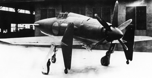
Kyushu J7W1 Shinden was an unorthodox fighter designed to intercept US bombers at high speed and high altitude. Although just two were completed, it was the only canard aircraft ordered into production during World War II. Exhaust from two cylinders flowed out the two ejector slits atop the engine cowling.

In early 1943, the IJN issued 18-Shi Otsu specification calling for a land-based fighter capable of intercepting enemy bombers. The aircraft should achieve 460 mph (740 km/h) at 28,543 ft (8,700 m), reach 26,247 ft (8,000 m) in 10.5 minutes, have a service ceiling of 39,370 ft (12,000 m), and carry four 30 mm cannons. Tsuruno worked up a design for such an aircraft and submitted it to the IJN. The IJN liked the design but was hesitant to move forward with the radical, untested configuration. Tsuruno was able to work with the First Naval Air Technical Depot (Dai-Ichi Kaigun Koku Gijitsusho) at Yokosuka to develop a proof of concept, designated MXY6.

The Yokosuka MXY6 was a glider of all wooden construction possessing a canard layout with fixed tricycle landing gear. The aircraft featured a foreplane with elevators mounted to its nose for pitch control. The swept wings were mounted to the rear fuselage, and each wing had a vertical stabilizer with a rudder mounted near its mid-point. Three of the gliders were built by Chigasaki Industry Ltd (Chigasaki Seizo KK). Piloted by Tsuruno, the MXY6’s first flight was made in January 1944. Later, one of the gliders was fitted with a 22 hp (16 kW) Nippon Hainenki Semi 11 [Ha-90] engine turning a wooden, fixed-pitch, two-blade propeller. The engine was not intended make the MXY6 fully operational under its own power, but it would enable the aircraft to sustain flight and prolong its glide. The MXY6’s flight tests indicated that Tsuruno’s design was sound. The aircraft handled well at low speeds and resisted stalling. Based on the positive preliminary tests of the MXY6, the IJN decided to proceed with Tsuruno’s 18-Shi Otsu design in February 1944. The aircraft would be built by the Kyushu Airplane Company (Kyushu Hikoki KK), and it was designated J7W1 Shinden (Magnificent Lightning).

Yokosuka_MXY6_Glider

One of the Yokosuka MXY6 gliders that survived to the end of the war and was found by US forces. The glider validated the basic configuration that was later applied to the J7W1.

Kyushu Airplane Company was founded in October 1943 as a subsidiary of the Watanabe Iron Works Ltd (Watanabe Tekkosho KK). Kyushu was selected as the manufacturer because it had both workers and production facilities that were available. Kyushu had no experience designing high-performance fighter aircraft, but the company would be aided by Tsuruno and the First Naval Air Technical Depot. An official order for the J7W1 was issued in June 1944, with the prototype’s first flight expected in January 1945.

The Kyushu J7W1 Shinden used the same layout as the MXY6, having a canard configuration with a swept, rear-mounted wing and tricycle undercarriage. The aircraft consisted of an aluminum airframe covered by aluminum panels, forming a monocoque structure. Depending on location, the panels were either flush riveted or spot welded in place. The control surfaces were skinned with aluminum. The foreplane had two spars and was mounted to the extreme nose of the aircraft at a one-degree angle of incidence. A leading-edge slat was deployed with the flaps. On the foreplane’s trailing edge was a two-section flap. The first section acted as a traditional flap that extended 26 degrees. The second section on the trailing edge acted as an elevator.

Mounted in the fuselage between the foreplanes were four 30 mm Type 5 cannons, each with 60 rounds per gun. Each cannon was 7 ft 2 in (2.19 m) long and weighed 154 lb (70 kg). The cannons were slightly staggered to allow for clearance of their respective feed belts and keep the fuselage as narrow as possible. A compartment under the cannons collected the spent shell casings because of concerns that they would strike the propeller if they were ejected from the aircraft. Two 7.9 mm machine guns with 75 rounds per gun were planned for the very front of the nose and could be used for either training or target ranging. As ranging guns, they would help ensure that the cannon shells hit the intended target and not waste the limited ammunition supply. No armament was fitted to the prototype, and ballast weight was used to simulate the cannons.

Kyushu-J7W1-Shinden-left

The wheels under the vertical stabilizers were added after the aircraft’s first flight attempt ended with bent propeller blades. Note the long landing gear’s relatively short wheel base.

Behind the cannons was the single-seat cockpit, which was covered by a rearward-sliding glazed canopy. The pilot was protected by 2.76 in (70 mm) of armored glass in the front windscreen and a .63 in (16 mm) bulkhead by the cannons. Passageways ran on both sides of the aircraft between the cockpit and outer skin. Flight controls, hydraulic lines, and wiring ran in these passageways, which were accessible via removable outer skin panels. Under and slightly behind the cockpit was a 106-gallon (400-L) self-sealing fuel tank made of .87 in (22 mm) thick rubber.

Directly behind the cockpit was a 44-gallon (165-L) oil tank, followed by a Mitsubishi [Ha-43] 42 (IJN designation MK9D) engine. The [Ha-43] was a two-row, 18-cylinder, air-cooled engine. The [Ha-43] 42 had two-stage supercharging, with the first stage made up by a pair of transversely-mounted centrifugal impellers, one on each side of the engine. The shaft of these impellers was joined to the engine by a continuously variable coupling. The output from each of the first stage impellers joined together as they fed the second stage, two-speed supercharger mounted to the rear of the engine and geared to the crankshaft. As installed in the J7W1, the engine produced 2,030 hp (1,514 kW) at 2,900 rpm with 9.7 psi (.67 bar) of boost for takeoff. Military power at 2,800 rpm and 5.8 psi (.40 bar) of boost was 1,850 hp (1,380 kW) at 6,562 ft (2,000 m) in low gear and 1,660 hp (1,238 kW) at 27,559 ft (8,400 m) in high gear.

Kyushu-J7W1-Shinden-front

The prototype was unarmed, but four 30 mm cannons, each capable of firing 500 rounds per minute, were to be mounted in the nose. The projectile from each 30 mm shell weighed 12.3 oz / 5,401 grains (350 g).

The engine was mounted in the center of the fuselage and atop the wingbox. An extension shaft approximately 29.5 in (750 mm) long extended back from the engine to a remote propeller reduction gear box. The extension shaft passed through an extended housing that was mounted between the engine and the propeller gear reduction. The gear reduction turned the propeller at .412 times crankshaft speed and also drove a 12-blade cooling fan that was 2 ft 11 in (900 mm) in diameter. A screen was placed in front of the fan to prevent any debris from exiting the rear of the aircraft and hitting either the fan or propeller. Mounted to the propeller shaft was a 11 ft 2 in (3.40 m) diameter, metal, six-blade, constant-speed, VDM (Vereinigte Deutsche Metallwerke)-type propeller built by Sumitomo Metal Industries Ltd, Propeller Division (Sumitomo Kinzoku Kogyo KK, Puropera Seizosho). The propeller had approximately 29 in (740 mm) of ground clearance with the aircraft resting on all of its landing gear. If bailing out of the aircraft was needed, the pilot could detonate an explosive cord that would sever the propeller and gear reduction.

Cooling air for the [Ha-43] engine was taken in via an oblique inlet mounted on each side of the fuselage just behind the cockpit. Flaps at the inlet’s opening were raised to decrease the flow of cooling air to the engine. Cooling air entered the inlets, passed through the fins on the engine’s cylinders, traveled along the outside of the extension shaft housing, passed through the cooling fan, and exited around the spinner or an outlet under the rear of the aircraft. Two intakes, one on each side of the aircraft, were mounted to the cooling inlet. These intakes ducted induction air through the cooling air duct and directly into the transversely mounted superchargers.

Kyushu-J7W1-Shinden-Ha-43-42-engine

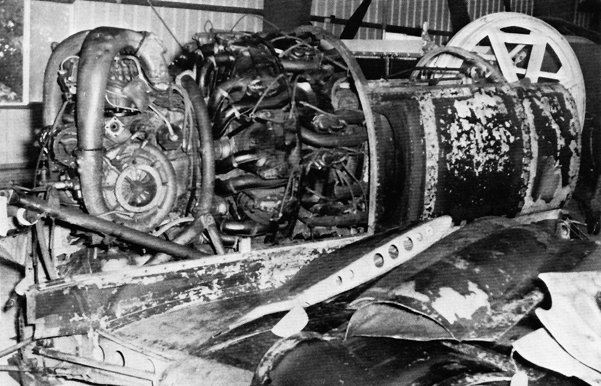
The Mitsubishi [Ha-43] 42 engine installed in the J7W1 as seen post-war. The front of the aircraft is on the left. One of the two transversely-mounted, first-stage superchargers can be seen left of the engine. The oil cooler duct is in place and blocking the view of the extension shaft to the right of the engine. On the wing is the middle panel of the supercharger’s inlet scoop.

On each side of the fuselage directly behind the induction scoop was an inlet for an oil cooler. For each of the two oil coolers, after air passed through the cooler, it was mixed with the exhaust of four cylinders and ejected out a slit on the side of the fuselage just before the spinner. The ejector exhaust was used to help draw air through the oil coolers. The same philosophy applied to the exhaust from six cylinders on the bottom of the engine. These were ducted into an augmenter that helped draw cooling air through the cowling and out an outlet under the spinner. The exhaust from the remaining four cylinders, which were located on the top of the engine, exited via two outlets arranged atop the cowling to generate thrust.

The leading edge of the J7W1’s wing was swept back 20 degrees, and the trailing edge was swept back six degrees. The wings were mounted with no incidence angle. The inner wing from the wingbox to the rudder had 2.5 degrees of dihedral, and the outer wing from the rudder to the tip had zero dihedral. The structure of each wing was formed with three spars. The front spar ran along the wing’s leading edge. The center, main spar was swept back 14.5 degrees and ran in front of the main landing gear wells. A rear spar was swept forward 3.5 degrees and ran from the wingbox to just behind the main gear mount. A vertical stabilizer extended above and below the rear spar. The vertical stabilizer was mounted at approximately the midpoint of each wing and extended past the wing’s trailing edge. Initially, nothing was mounted under the vertical stabilizers, but a wheel was later added under each stabilizer to prevent propeller ground strikes. A rudder ran the entire 7 ft 3 in (2.20 m) height of each vertical stabilizer. Each wing housed a 53-gallon (200-L) fuel tank and a 20-gallon (75-L) anti-detonation fluid (water/methanol) tank for injection into the engine. Split flaps were positioned along the trailing edge of the wing between the vertical stabilizer and the fuselage. The flaps on the main wing extended 20 degrees. Two hardpoints under each outer wing could accommodate 66 or 132 lb (30 or 60 kg) bombs.

Kyushu-J7W1-Shinden-rear

Rear view of the J7W1 showing its six-blade propeller and the engine’s 12-blade cooling fan in the rear of the cowling. The exhaust augmenter outlet can be seen on the bottom of the cowling. Note the rudders extending the entire height of the vertical stabilizers.

When deployed, the legs of the main gear were angled forward more than the nose gear. This effectively extended the nose gear and caused the aircraft to sit five-degrees nose-high while on the ground. This stance minimized the rotation needed to achieve liftoff, which is very important in the pusher aircraft. The main gear was mounted forward of the vertical stabilizers. The swiveling but non-steerable nose gear retracted forward, and the main gear retracted inward. Gear retraction and extension were powered hydraulically. At approximately 5 ft 11 in (1.8 m) long, the landing gear was quite tall to allow clearance for the propeller. The gear had a fairly wide track of 15 ft (4.56 m), but the wheelbase was short at only 10 ft 2 in (3.11 m). The short wheelbase combined with the tall gear legs and the aircraft’s high center of gravity could have given the J7W1 undesirable ground handling characteristics.

The J7W1 had a 36 ft 5 in (11.11 m) wingspan, was 32 ft (9.76 m) long, and was 12 ft 10 in (3.92 m) tall. The aircraft had a top speed of 466 mph (750 km/h) at 28,543 ft (8,700 m), a cruising speed of 276 mph (444 km/h), and a stalling speed of 107 mph (172 km/h). The J7W1 could climb to 26,247 ft (8,000 m) in 10 minutes and 40 seconds and had a 39,370 ft (12,000 m) service ceiling. The aircraft had an empty weight of 7,639 lb (3,465 kg), a normal weight of 10,864 lb (4,928 kg), and a maximum weight of 11,526 lb (5,228 kg). Cruising at 9,843 ft (3,000 m) gave the J7W1 a 528-mile (850-km) range. The aircraft was stressed for a maximum speed of 575 mph (926 km/h) and 7 Gs.

Kyushu-J7W1-Shinden-front-left

The various ducts on the side of the J7W1 are illustrated in this image. The flaps to reduce cooling air can be seen just before the oblique inlet on the side of the aircraft. The smaller scoop that fed air into the supercharger is mounted to the outside of the cooling air inlet. The oil cooler inlet can be seen just behind the tapered fairing for the induction scoop.

While the prototype was still under construction, the IJN ordered the J7W1 into production in May 1944 to counter the imminent threat of American bombing raids with the Boeing B-29 Superfortress. Ultimately, the production schedule called for Kyushu to produce 30 aircraft per month, and the Nakajima Aircraft Company, Ltd (Nakajima Hikoki KK) would build 120 units per month. In June 1944, the United States Army Air Force began conducting bombing raids against Japan using the B-29. To intercept these bombers and disrupt these raids were the exact purposes for which the J7W1 was designed. In September 1944, a mockup of the J7W1 was inspected by the IJN, and wind tunnel tests of a scale model had yielded positive results.

The J7W1 was built at Kyushu’s Zasshonokuma Plant, near Fukuoka city. The airframe was nearing completion in January 1945, when the first flight was originally scheduled to be conducted. Bombing raids delayed delivery of the [Ha-43] 42 engine, which finally arrived in April. The J7W1 was finally completed on 10 June and was subsequently disassembled and moved to Mushiroda Airfield (now Fukuoka Airport) in Fukuoka city on 15 June. Reassembled, the aircraft was inspected on 19 June, but bombing raids caused some delays. Ground tests were soon conducted and indicated a tendency for the engine to overheat due to a lack of cooling airflow. Tsuruno attempted the first flight in July, but as the J7W1 began to take flight, the engine’s torque induced a roll to the right. The aircraft’s nose went high and caused the propeller tips to strike the ground, bending the tips back.

Kyushu-J7W1-Shinden-repair-right-side

Following World War II, the J7W1 was repaired and then painted before the aircraft was shipped to the United States. The new panels are easily seen in this image prior to the aircraft being repainted. Note that there is no cockpit glass.

The J7W1 was repaired, and the second prototype’s propeller was installed. A tailwheel from a Kyushu K11W Shiragiku (White Chrysanthemum) trainer was added under each vertical stabilizer so that during an over-rotation, a propeller strike would not occur again. Yoshitaka Miyaishi took over the flight tests and started over with ground runs to assess the aircraft’s handling. The J7W1 made its first flight on 3 August 1945. Liftoff occurred at 126 mph (204 km/h), and the aircraft was not flown above 1,312 ft (400 m). The speed did not exceed 161 mph (259 km/h), and the flight lasted under 15 minutes, with the aircraft landing at 115 mph (185 km/h). The J7W1’s tendency to roll to the right persisted and needed much left aileron input to correct, but the aircraft behaved reasonably well otherwise. Two further flights were made on 6 and 8 August, each about 15 minutes in length. The aircraft’s basic handling was evaluated, and the landing gear was never retracted during the tests. The roll to the right was made worse with the flaps deployed and the engine producing more torque to maintain airspeed. The J7W1 exhibited a tendency for its nose to pitch down, which was countered by a steady pull on the control stick. The engine, extension shaft, and remote gear reduction caused some vibration issues.

Modifications were contemplated to neutralize the engine’s torque reaction and correct the aircraft’s handling. A proposition was made to increase the foreplane’s angle of incidence to three degrees and change the main wing’s flap deployment to 30 degrees. In addition, the oil cooler needed to be improved. It was decided that speed tests would be initiated on the aircraft’s next flight, scheduled for 17 August. However, all work was stopped with the Japanese surrender on 15 August, and much of the aircraft’s documentation was burned on 16 August.

Kyushu-J7W1-Shinden-display

The J7W1 on display in Japan after it was repaired and painted. The inlet for the right oil cooler can be seen just behind the induction scoop, and the oil cooler’s exit can be seen right before the propeller. Note that the flaps are partially deployed.

At the end of the war, the second J7W1 was nearly complete and waiting on its [Ha-43] 42 engine, and the third aircraft was under construction. No other examples were completed to any meaningful level. The third J7W1 was planned to have the three-degree foreplane angle of incidence and a [Ha-43] 43 engine that produced an additional 130 hp (97 kW) for takeoff. This engine would have a single impeller for its first-stage, continuously-variable supercharger. The intake for the engine was moved to the inside of the J7W1’s cooling air inlets. The fourth and later aircraft would incorporate the changes from the third and also have a four-blade propeller 11 ft 6 in or 11 ft 10 in (3.5 m or 3.6 m) in diameter. The four-blade propeller had wider blades, was easier to manufacture, and was intended to cure some of the J7W1’s tendency to roll to the right. Beginning with the eighth aircraft, a 2,250 hp (1678 kW) [Ha-43] 51 engine would be installed. The [Ha-43] 51 had a single-stage, three-speed, mechanical supercharger instead of two-stage supercharging with a continuously-variable first stage.

The second and third J7W1 were both destroyed following the Japanese surrender. The first prototype, with around 45 minutes of flight time, was captured by US Marines and found to have all of the cockpit glass removed and some body panels damaged, possibly from a typhoon. For many years, it was thought that the first prototype was destroyed and that the second aircraft was captured by US forces, but this was later found to be incorrect. Under US orders, the aircraft was repaired and repainted while still in Japan. Most pictures of the J7W1 are immediately after the repairs have been made or shortly after it was painted. In almost all of the pictures, the cockpit glass is missing. In October 1945, the J7W1 was disassembled and shipped to the United States.

Kyushu-J7W1-Shinden-Tsuruno

Six US Servicemen and four Japanese dignitaries pose next to the J7W1. Masayoshi Tsuruno, the aircraft’s designer, is the fourth from the left. The men give a good indication of the aircraft’s tall stance and overall size.

The surviving J7W1 was assigned ‘Foreign Evaluation’ FE-326 (later T2-326), and attempts were made to bring the aircraft to a flightworthy status. It is believed that most of this work, including new cockpit glass and installing several American flight instruments, was conducted in mid-1946 at Middletown Air Depot (now Harrisburg International Airport) in Pennsylvania. In September 1946, the aircraft was moved to the Orchard Field Airport (now O’Hare Airport) Special Depot in Park Ridge, Illinois. Instructions indicated that the J7W1 could be made airworthy if an overhauled engine was found, but this never occurred and the aircraft was not flown in the United States. The J7W1 was transferred to the Smithsonian National Air and Space Museum in 1960. The aircraft is preserved in a disassembled and unrestored state, with the [Ha-43] 42 engine still installed in the fuselage. Amazingly, video of the aircraft’s aborted first flight attempt and eventual first flight can be found on YouTube.

Around 2016, a full-size model of the J7W1 was built by Hitoshi Sakamoto. The model was on special display at the Yoichi Space Museum in Hokkaido, but it is not known if it is still there.

A turbojet version of the aircraft had been considered from the start, but a suitable powerplant had not been built in Japan by the close of the war. Designated J7W2 Shinden-Kai, the jet aircraft most likely would have had shorter landing gear, with additional fuel tanks in the wings occupying the space formerly used by the longer gear. There is no indication that the J7W2 had progressed beyond the preliminary design phase before the war’s end.

Kyushu-J7W1-Shinden-NASM

Today, J7W1 is disassembled but fairly complete. However, the years of storage have led to many bent and dented parts. The aircraft was long stored in the Smithsonian National Air and Space Museum’s Paul E. Garber facility, but the cockpit and foreplanes are on display at the Steven F. Udvar-Hazy Center in Chantilly, Virginia. (NASM image)

Sources:
Zoukei-mura Concept Note SWS No. 1 J7W1 Imperial Japanese Navy Fighter Aircraft Shin Den by Hideyuki Shigete (2010)
Japanese Secret Projects by Edwin M. Dyer III (2009)
Japanese Aircraft of the Pacific War by René J. Francillon (1979/2000)
– “Kyushu Airplane Company” The United States Strategic Bombing Survey, Corporation Report No. XV (February 1947)
Encyclopedia of Japanese Aircraft 1900–1945 Vol. 4: Kawasaki by Tadashi Nozawa (1966)
The XPlanes of Imperial Japanese Army & Navy 1924–45 by Shigeru Nohara (1999)
War Prizes by Phil Butler (1994/1998)
https://www.secretprojects.co.uk/threads/kyushu-J7W1-shinden-J7W2-shinden-kai.16914/
https://airandspace.si.edu/collection-objects/kyushu-j7w1-shinden-magnificent-lightning

McDonnell-XP-67-top

McDonnell Aircraft Corporation XP-67 Fighter

By William Pearce

On 20 February 1940, the Army Air Corps (AAC) issued Request for Data R40-C that sought designs of new fighter aircraft capable of 450 mph (724 km/h), with 525 mph (845 km/h) listed as desirable. The AAC encouraged aircraft manufacturers to propose unconventional designs. The McDonnell Aircraft Corporation proposed four variants of its highly-streamlined Model 1 (often called Model I), the company’s first design. Each of the four Model 1 variants were powered by a different engine, and all the engines produced over 2,000 hp (1,491 kW). The Model 1’s engine was buried in the fuselage and drove wing-mounted pusher propellers via extensions shafts and right-angle gear boxes. Although not selected for R40-C, the AAC did purchase engineering data and a wind tunnel model of the design powered by an Allison V-4320 engine.

McDonnell-Model-2-original

The McDonnell Model 2 as originally proposed was similar to the Model 1 but with Continental XI-1430 engines mounted under the wings. This configuration was found to create excessive drag.

McDonnell worked with the AAC to refine the Model 1 design and submitted the Model 2 (often called Model II) on 30 June 1940. The Model 2 had a crew of two, and two wing-mounted Continental XI-1430 engines replaced the single engine in the fuselage. The aircraft retained the basic shape of the Model 1’s fuselage and wings, but the engines were initially mounted directly under the wings in a tractor configuration. The engine mounting was changed as a result of wind tunnel tests. The new configuration was to mount the engine forward of the wing with a nacelle that housed a turbosupercharger extending back past the wing’s trailing edge. The nacelle was mounted mid-wing, and this design minimized drag. To further reduce drag, the Model 2 design was modified to incorporate fairings that blended the fuselage and engine nacelles to the wings. In addition, the design had the pilot as the sole occupant. The single-seat, blended design was called the Model 2A (often called Model IIA), and it was submitted to the AAC on 24 April 1941.

On 5 May 1941, McDonnell submitted preliminary specifications of the Model 2A to the AAC. Under these specifications, the aircraft had a wingspan of 55 ft (16.8 m), a length of 42 ft 3 in (12.9 m), and a height of 14 ft 9 in (4.5 m). The Model 2A had a calculated speed of 500 mph (805 km/h) at 35,000 ft (10,668 km), 472 mph (760 km/h) at 25,000 ft (7,620 m), and 384 mph (618 km) at 5,000 ft (1,524 m). The aircraft would climb to 25,000 ft (7,620 m) in 9 minutes and have a service ceiling of 41,500 ft (12,649 m). At a cruising speed of 316 mph (509 km/h), maximum range was 2,400 miles (3,862 km) with 760 gallons (2,877 L) of internal fuel. The Model 2A had an empty weight of 13,953 lb (6,329 kg), a gross weight of 18,600 lb (8,437 kg), and a maximum weight of 21,480 lb (9,743 kg).

McDonnell-Model-2-revised

The Model 2 was revised with the engines mounted forward of the wings with streamlined nacelles mounted mid-wing. This produced a more attractive aircraft, very similar to the Model 1. However, the relation to the XP-67 is clear.

McDonnell continued to work with the AAC to refine the design of the Model 2A. On 30 September 1941, the Army Air Force (AAF—the AAC was renamed in June 1941) issued a contract to McDonnell to build two prototypes of the Model 2A interceptor pursuit fighter as the XP-67. The aircraft was assigned Materiel Experimental code MX-127. The first aircraft was scheduled to be delivered on 29 April 1943, with the second example delivered six months later on 29 October 1943. The XP-67 had a fairly conventional layout for a single-seat, twin-engine aircraft with tricycle undercarriage. What was not conventional was the extensive blending of the fuselage and engines nacelles to the aircraft’s wings to maintain true airfoil sections throughout the entire aircraft. The end result was a streamlined appearance.

The XP-67 was constructed of an aluminum frame with aluminum skin that formed a monocoque structure. All control surfaces consisted of a fabric covered aluminum frame, although aluminum skinning was later proposed for production aircraft. Effort was expended to keep the XP-67’s surface smooth and make everything flush. Initially, a door on the left side of the pressurized cockpit was to allow access. However, pressurization was dropped on the prototype, and a glazed, rearward-sliding canopy was used.

The wings had two spars, a dihedral of five degrees, and consisted of inner and outer wing sections. The outer wing section extended from the engine nacelle and was removable. Split flaps were located between the nacelle and fuselage. A small split flap existed on the outer side of the engine nacelle. The outer wing section’s trailing edge was occupied by an aileron. The ailerons drooped 15 degrees with deployment of the flaps, which had a maximum deployment of 45 degrees. However, it does not appear that the drooping ailerons were ever installed on the prototype. No hardpoints existed under the wings for bombs or drop tanks.

McDonnell-Model-2A-drawing

The Model 2A as originally proposed in May 1941 was essentially the latest Model 2 design but with large fairings that blended the fuselage and engine nacelles to the wing. This design was contracted as the XP-67.

Mounted to each wing was a liquid-cooled, Continental XI-1430 inverted V-12 engine. Initially, clockwise-rotating (right-handed) XI-1430-1 engines were to be used. In June 1942, the engines were switched to an XI-1430-17 installed on the right wing (clockwise, right-handed rotation) and an XI-1430-19 installed on the left wing (counterclockwise, left-handed rotation). Each engine of the first prototype turned a cuffed, four-blade Curtiss Electric constant-speed propeller that was 10 ft 6 in (3.2 m) in diameter. However, the cuffs were installed after the first aircraft was completed. In April 1943, McDonnell proposed installing Curtiss Electric contra-rotating propellers on the second XP-67 prototype, noting that such a change would increase the aircraft’s speed by 7–10 mph (11–16 km/h) and climb rate by 400 fpm (2.0 m/s).

The engine nacelle extended back from each engine and housed a General Electric D-23 turbosupercharger. Engine exhaust was directed straight back from the nacelle to gain some thrust. Initially, it was proposed that each engine would have a coolant radiator located in the fuselage. This was changed to each engine having two coolant radiators housed in the engine nacelle and located directly under the rear of the engine. The engine nacelles were blended into the wing, and several intakes were incorporated into the wing’s leading edge. For both engine nacelles, the intakes closest to the nacelle passed air to a cooling jacket around the exhaust manifold. The center intake directed air through the two coolant radiators per engine and to the turbosupercharger. The intakes farthest from the engine each led to an oil cooler.

An oil tank in each wing held 26 gallons (98 L) for each engine. The aircraft’s normal fuel load was 282 gallons (1,067 L), but 478 gallons (1,809 L) of additional fuel could be housed in the aircraft’s four fuel tanks located in the fuselage and wing. This brought the XP-67’s total fuel capacity to 760 gallons (2,877 L). The aircraft’s tricycle landing gear was hydraulically-powered and fully retractable. The nose wheel was swiveled, but was not steerable, and folded back into the fuselage. The main gear was mounted just inboard of the engine nacelles and folded inward. In early 1942, the AAF requested that the main gear fold into the engine nacelle, necessitating a complete redesign of the nacelles to accommodate the rearward retracting main wheels. The horizontal stabilizer had 9.55 degrees of dihedral and was mid-mounted to the aircraft’s vertical stabilizer. Like the outer wing panels, the tail was detachable for transporting the aircraft by ground. The XP-67 airframe was stressed for +8 and -4 Gs and had a diving limit of 604 mph (972 km/h) indicated.

McDonnell-XP-67-nacelle-LMAL

An XI-1430-17 with a GE D-23 turbosupercharger installed in the McDonnell XP-67 wing section for tests at the Langley Memorial Aeronautical Laboratory in September 1943. The tests were conducted to evaluate the cooling ducts of the XP-67’s radical blended design. The top image illustrates the unusual ducting of the XP-67’s nacelles, which were duplicated on the opposite side. Closest to the spinner is the exhaust manifold cooling air duct. The large middle duct was for the coolant radiator and engine intake. The outer duct was for the oil cooler. The bottom image shows the turbosupercharger, which was installed so that the exhaust provided additional thrust. Note the radiator cooling air exit duct on the landing gear door and the cuffed propellers. (LMAL images)

The XP-67’s armament changed as the aircraft was developed. Initially, the aircraft would have four 20 mm cannons with 166 rounds per gun and six .50-cal machine guns with 500 rounds per gun. The cannons would be installed on the sides of the cockpit, just behind the pilot. The machine guns were to be installed just behind the cannons. On 5 August 1941, the AAF requested that two 37 mm cannons be installed in place of two 20 mm cannons. By 16 August, the armament was revised again to six 37 mm cannons with 45 rounds per gun and no other guns. The 37 mm cannons were installed in the blended-wing’s leading edge between the cockpit and engine nacelle. The three cannons on each side of the fuselage were outside of the propeller arc. On 20 October, it was suggested that the aircraft’s design should incorporate provisions to replace four of the 37 mm cannons with four 20 mm cannons. On 8 November, it was decided that the first aircraft would have six 37 mm cannons, and the second aircraft would have two 37 mm and four 20 mm cannons.

Extensive wind tunnel tests were conducted on various XP-67 models throughout 1942 and 1943. These tests led to many minor changes in the aircraft. Much of this testing was focused on the extensive fairing used to blend the wing and fuselage. The cooling system was also carefully scrutinized with many minor changes taking place to the cooling ducts. A full-size mockup of the XP-67 was inspected in mid-April 1942, which led to more changes. The most significant changes were lengthening the aircraft’s nose by 15 in (381 mm) and changing the flight control actuation system from push-pull rods to cables. In May, a fuselage section was built to test fire the 37 mm cannons. The tests proved satisfactory, but McDonnell redesigned the 37 mm cannon installation in October, necessitating another mockup and more tests. The new 37mm cannon installation mockup successfully passed its tests in March 1944, but the armament was never installed in the prototype. On 17 June 1942, the decision was made to finish the prototype without a pressurized cockpit. In April 1943, there were discussions of cancelling the XP-67, but the aircraft was seen as a good way to test the experimental wing blending, cannon armament, and XI-1430 engines.

McDonnell-XP-67-construction

The McDonnell XP-67 nearly complete in mid-November 1943. Even though the nacelle’s duct design was found to be insufficient in the wind tunnel tests, the aircraft was not modified with a new design until later. Note the covered ports for 37 mm cannons on each side of the cockpit and that the propellers do not have their cuffs installed.

McDonnell had built a full-scale XP-67 engine nacelle for testing the XI-1430 engine installation. Tests were conducted by McDonnell starting in May 1943. After accumulating almost 27 hours of operation, the rig was sent to the National Advisory Committee for Aeronautics (NACA) at the Langley Memorial Aeronautical Laboratory (LMAL, now Langley Research Center) in Virginia. The NACA added about 17.5 hours to the engine conducting tests in August and September to analyze the installation’s effectiveness for cooling the coolant, oil, and intercooler. The tests indicated that the cooling system was insufficient. The nacelle with revised ducts was then shipped to Wright Field in Dayton, Ohio in October 1943. Wright field added another 6.5 hours to the engine, bringing the total to 51 hours. The new ducts proved satisfactory, reducing the drag of the ducts by 25 percent and improving cooling by 200 percent. However, excessive vibrations occurred between the engine and its mounting structure, necessitating a more rigid mount. McDonnell was allowed to proceeded with testing the first XP-67, although the prototype would not be changed until after its first flight when additional changes beyond the cooling system would most likely need to take place. Wind tunnel tests had indicated that the horizontal stabilizer would need to be raised by 12 in (305 mm) to improve stability. McDonnell was instructed to stop work on the second prototype until successful flight tests of the first aircraft had been conducted.

Serial number 42-11677 was given to the first XP-67, and serial number 42-11678 was given to the second prototype. Unofficially, the XP-67 was given the name ‘Moonbat’ or just ‘Bat,’ but it does not appear that an official name was ever bestowed upon the aircraft. With all the design changes since the XP-67 was initially contracted, the aircraft’s specifications had changed. The wingspan remained at 55 ft (16.8 m), but the length increased 2 ft 6 in (.8 m) to 44 ft 9 in (13.6 m), and the height increased 1 ft (.3 m) to 15 ft 9 in (4.8 m). The standard fuel load remained at 280 gallons (1,060 L), but the additional fuel load decreased by 25 gallons (95 L) to 455 gallons (1,722 L), giving a total maximum internal fuel load of 735 gallons (2,782 L). The XP-67’s weight had increased by 3,792 lb (1,720 kg), resulting in an empty weight of 17,745 lb (8,049 kg), a gross weight of 22,114 lb (10,031 kg), and a maximum weight of 24,836 lb (11,265 kg). A reduction in performance accompanied the weight increase, resulting in an estimated speed of 448 mph (720 km/h) at 25,000 ft (7,620 m), which was a 24 mph (39 km/h) reduction, and 367 mph (591 km/h) at sea level. The time to climb to 25,000 ft (7,620 m) was increased by nearly five minutes to 14.8 minutes, and the service ceiling decreased 4,100 ft (1,250 m) to 37,400 ft (11,400 m). The XP-67’s cruising speed decreased 46 mph (74 km/h) to 270 mph (435 km/h), but maximum range was little changed at 2,385 miles (3,838 km) with 735 gallons (2,782 L) of fuel.

McDonnell-XP-67-right-front

The completed XP-67 with revised nacelle cooling ducts and after the horizontal stabilizer was raised 12 in (305 mm). The most noticeable duct modification was to the exhaust manifold cooling intake, which was changed to a scoop. Note that the propellers rotated in opposite directions.

On 1 December 1943, the XP-67 had its XI-1430 engines installed and was ready for ground tests. However, both engines caught fire and damaged the aircraft on 8 December. The fires were caused by issues with the exhaust manifolds. The XP-67 was repaired and made its first flight on 6 January 1944, taking off from Scott Field in Belleville, Illinois. The flight was nearly two years later than the anticipated first flight when the XP-67 contract was originally issued. Test pilot Ed E. Elliott had to cut the flight to just six minutes due to both turbosuperchargers overheating, which resulted in small fires. During the short flight, the XP-67 exhibited good handling characteristics.

The aircraft was again repaired, with the second and third flights occurring on 26 and 28 January 1944. On 1 February, the aircraft’s fourth flight was cut short due to a main bearing failure on the left engine caused by an unintentional overspeed of the engine. The cockpit canopy also detached during the flight. While the XP-67 was down for repairs and new XI-1430 engines, the horizontal stabilizer was raised 12 in (305 mm). The cooling ducts in the engine nacelles were also modified, with the most noticeable being the exhaust shroud inlet, which was changed to more of a scoop. The updated aircraft flew again on 23 March 1944 and demonstrated improved stability, but one turbosupercharger failed at 10,000 ft (3,048 m).

In April 1944, it was reported that the engines were running too cool. The closed main gear door formed part of the air duct aft of the radiator. However, the gear doors did not seal tightly and caused an excessive amount of air to exit the duct. This resulted in too much air passing through the radiator and reducing the engine temperature below ideal levels. McDonnell was allowed to install a thermostat on the prototype to help control coolant temperatures but was also told that such issues would not be acceptable on production aircraft. Around this same time, construction of the second prototype was allowed to proceed with the exception of parts that would be affected by an engine change.

McDonnell-XP-67-top

The unusual planform of the XP-67 is illustrated in this view. The two ports in the middle of each nacelle were the forward exit for the exhaust manifold cooling air. The rear exit is denoted by the white staining at the end of the nacelle. The outer wing section was detachable just outside of the nacelle.

In May 1944, three AAF pilots flew the XP-67 and reported that the XI-1430 engines ran rough and seemed underpowered. Tests indicated that at normal power, the engines were only delivering 1,060 hp (790 kW), well below the expected 1,350 hp (1,007 kW). The XP-67 was noted for having high control forces at high speeds, exhibiting a Dutch roll indicating some directional instability, and not making a good gun platform. The maximum speed with the engines delivering 1,600 hp (1,193 kW) at 3,200 rpm was 357 mph (574 km/h) at 10,000 ft (3,048 m) and 393 mph (632 km/h) at 20,000 ft (6,096 m). From these values and other tests, McDonnell calculated that the XP-67 could attain 405 mph (652 km/h) at 25,000 ft (7,620 m) at the same power setting. Takeoff speed was 130 mph (209 km/h); the clean stall speed was 118 mph (190 km/h) with buffeting starting at 140 mph (225 km/h); and the aircraft had a high landing speed of 120 mph (193 km/h). In general, the XP-67 was found to be inferior to other fighters currently in production.

McDonnell got permission to install contra-rotating propellers on the first prototype when the engines were ready, and they were expected in June 1944. No information has been found indicating that the contra-rotating versions of the XI-1430 were delivered. In June, it was decided to install 11 ft (3.4 m) diameter four-blade Aeroproducts propellers rather than contra-rotating propellers. However, tests would continue with the Curtiss propellers until the Aeroproducts were ready. It was also noted that the XP-67 had experienced no engine fires since its fourth flight, and the aircraft had completed about 50 flights without any serious issues.

McDonnell-XP-67-in-flight

The limited flight trials of the XP-67 indicated the aircraft handled fairly well. It was noted as underpowered and slightly unstable. Overall, visibility was said to be poor, with the engine and fairing blocking most of the view to the side and rear. Formation flying would have been difficult, as the pilot was unable to see their wingtips.

In July 1944, some in the AAF felt that the XP-67 program was expensive and served no purpose. However, others felt that the aircraft was a unique platform that would allow the testing of the six 37 mm cannons. In addition, the possibility existed to install 12 .50-cal machine guns or eight 20 mm cannons. The aircraft was seen as a good test machine, even if its performance fell below what was originally specified. It was decided to complete tests on the current aircraft to assess the blended design and then consider the possibility of armament trials.

McDonnell had long sought to change the aircraft’s engines. On 19 January 1944, McDonnell proposed discarding the XI-1430s for the second prototype and using either two-stage Allison V-1710 or Rolls-Royce Merlin RM 14SM (100-series prototype) piston engines. In addition, each engine nacelle would house a Westinghouse 9.5 (J32) turbojet behind the piston engine. The mixed-power proposal was brought up again on 16 March 1944, now using an Allison V-1710-199 (F32R) piston engine and either a Rolls-Royce W2B/37 turbojet or a GE I-20 (J39) turbojet in the nacelle. With mixed power plants, the aircraft had an estimated top speed at sea level of 500 mph (805 km/h). The engine issue was discussed again in July 1944, with McDonnell now suggesting a Rolls-Royce Merlin RM 14SM piston engine paired with a GE I-20 (J39) turbojet in each nacelle. However, AAF felt that the aircraft would need a complete redesign to incorporate different piston engines with turbojets.

Since its initial design in May 1941, there were suggestions of using a modified version of the XP-67 for photo reconnaissance. In April 1942, McDonnell suggested that the aircraft’s range could be extended to 4,000 miles (6,437 km) at a cruise speed of 200 mph (322 km/h), which would be a 20-hour flight. For this, two of the 37 mm cannons would need to be omitted and six additional fuel tanks installed along with 280 lb (127 kg) of ballast in the nose. With the extra tanks, the aircraft’s internal fuel capacity was 1,290 gallons (4,883 L). This concept was not pursued at the time, but the range extension was considered later for a photo-recon role.

McDonnell-XP-67E-model

A model of the XP-67E with its bubble canopy and mixed piston / turbojet power plants. It is not clear what engines (if any) are intended to be depicted by the model, but the nacelles were extended back to house the jet engine (LMAL image).

By July 1944, it was believed that a photo-recon version of the XP-67 would have inferior performance compared to the Lockheed F-5 (P-38). However, a mixed-power version of the aircraft was seen as a possible candidate as a photo-recon aircraft. The XP-67E was designed for the photo-recon role, and it incorporated mixed power, additional internal fuel tanks, and provisions for two 150-gallon (568-L) drop tanks mounted under the aircraft’s center section. In the XP-67E design, the engine nacelles were extended back to house the GE I-20 (J39) turbojet engine. Cameras were installed in the aft fuselage, and the XP-67E was unarmed. The fuselage was mostly unchanged, but the cockpit was enclosed in a rearward-sliding bubble canopy.

The XP-67 prototype had been undergoing modifications and repairs through August 1944. Perhaps the most major change was alerting the wing dihedral from 5 degrees to 7 degrees in an attempt to increase stability. The aircraft was ready to resume flight tests in early September. On 6 September 1944, the exhaust valve rocker of the No. 1 cylinder in the XP-67’s right engine broke while the aircraft was in flight at 10,000 ft (3,048 m). Exhaust gases unable to escape the cylinder backed up into the intake manifold and caused it to fail, resulting in a fire. The fire was first noticed at 3,000 ft (914 m) as the aircraft was preparing to land. Test pilot Elliott was able to land the XP-67 and stopped it to limit the flames from spreading. However, the brake failed after Elliott exited the aircraft, and wind turned the XP-67 so that the flames blew toward the fuselage. The XP-67 was nearly burned in half and damaged beyond repair. The aircraft had a total flight time of 43 hours. This event effectively killed the XP-67 project and the XP-67E photo-recon proposal. The entire program was suspended seven days later on 13 September, and on 24 October, McDonnell was notified that the XP-67 contract was cancelled. A formal Notice of Cancellation followed on 27 October 1944. The second prototype was about 15 percent complete and was subsequently scrapped. The total cost of the XP-67 program was approximately $4,733,476.92.

McDonnell-XP-67-fire-front

The XP-67 after the fire on 6 September 1944. Once on the ground, the fire from the right engine spread to the rear fuselage and left nacelle. The rear fuselage was nearly burned through and collapsed to the ground. An inglorious end to both the XP-67 and XI-1430 programs.

Sources:
Interceptor Pursuit Airplane Twin Engine Type XP Preliminary Specifications by McDonnell Aircraft Corporation (5 May 1941)
Memorandum Report on XP-67 Airplane, AAF No, 42-11677 by Osmond J. Ritland (19 May 1944)
Final Report on the XP-67 Airplane by John F Aldridge Jr. (31 January 1946)
Case History of XP-67 Airplane by Historical Division, Air Materiel Command (23 July 1946)
USAF Fighters of World War Two Volume Three by Michael O’Leary (1986)
U.S. Experimental & Prototype Aircraft Projects: Fighters 1939-1945 by Bill Norton (2008)