Category Archives: World War II

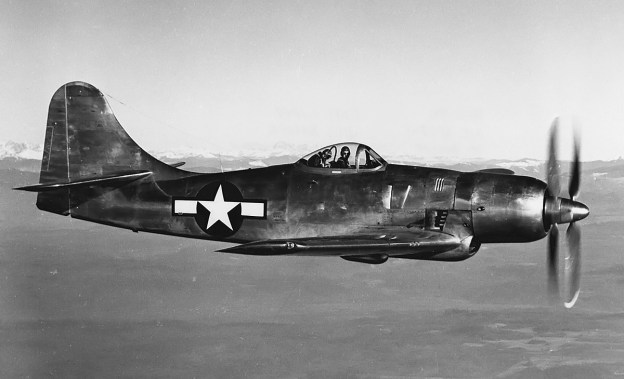
Boeing-XF8B-BuNo-57984-in-flight

Boeing XF8B Five-In-One Fighter

By William Pearce

In 1942, experience in the Pacific War made the United States Navy aware that their carrier-based fighter aircraft lacked the range needed to properly escort other aircraft while the home carrier stayed outside the combat radius of enemy aircraft. In addition, long-range ship-borne aircraft were needed to take the fight to the Japanese mainland. This prompted the Navy to search for a long-range, carrier-based fighter. The Boeing Airplane Company responded with its Model 400 design, which interested the Navy, and a contract for three prototypes was issued on 10 April 1943. The new aircraft was designated the Boeing XF8B.

Boeing-XF8B-BuNo-57984-in-flight

The first XF8B (BuNo 57984) on a test flight along with a piggyback flight engineer hunched over behind the pilot. Note the two separate exhaust stacks in the cowling and the four stacks behind the cowling.

From the start, Boeing had sought an agreement with the Navy in which Boeing would be given almost full control of the project and would develop the aircraft as they thought best. Part of the reason for this request was that the buyer, whether Navy or Army Air Force, had a habit of constantly issuing minor changes which often resulted in some developmental chaos on the part of the aircraft manufacturer. The Navy had already issued specifications for the XF8B, which included a top speed of 342 mph (550 km/h), a minimum speed of 79 mph (127 km/h), a takeoff distance with a 25-knot (29 mph / 46 km/h) headwind of 262 ft (80 m), an initial climb rate of 3,760 fpm (19.1 m/s), and a ceiling of 30,000 ft (9,144 m). Since Boeing had agreed to these specifications, the Navy felt that Boeing’s interest to develop the aircraft with little interference was in good faith and begrudgingly consented to Boeing’s request.

The Boeing XF8B was an all-metal monoplane with a conventional layout. What was less conventional about the XF8B was its Pratt & Whitney R-4360 28-cylinder engine with contra-rotating propellers, its large size, the inclusion of an internal bomb bay, and Boeing’s intention for the aircraft to be more than just a long-range fighter but also to be used as an interceptor, level bomber, dive bomber, and torpedo bomber. The multi-role characteristic of the XF8B led Boeing to refer to it as the “Five-In-One” aircraft.

A mock-up of the XF8B was completed in September 1943 and was inspected by the Navy in early October. The design of the aircraft was finalized on 7 October 1943. The XF8B’s fuselage had flat sides with an arched top and a relatively flat bottom. It was formed by aluminum panels riveted to aluminum formers and longerons. The cockpit was above the wing’s trailing edge and enclosed in a rearward sliding bubble canopy. The control stick moved fore and aft like normal, but left and right movement was limited by a pivot point to the upper half of the stick. This design was adopted to save space in the cockpit. The pilot was protected by armored glass and an armor plate in front of the cockpit and an armored seat. A 40 US gal (33 Imp gal / 151 L) oil tank was positioned forward of the cockpit. Below the cockpit was a bomb bay that could accommodate up to 3,200 lb (1,451 kg) of ordnance. However, the bomb bay’s size limited what could be carried to four 250 or 500 lb (113 or 227 kg) bombs or two 1,000 or 1,600 lb (454 or 726 kg) bombs. One 2,000 lb (907 kg) bomb could also be accommodated. For long range flight, a 270 US gal (225 Imp gal / 1,022 L) fuel cell could be installed in the bomb bay. Two snap-opening doors enclosed the bomb bay and would automatically open and close during bomb release. The doors could open or close in under one second. At the rear of the fuselage was a fully-retractable tail wheel.

Boeing-XF8B-BuNo-57984-flaps

Taken before the aircraft’s first flight, this image shows the XF8B’s large flaps that extended back some 32 in (.813 mm) as they were deployed. The door in front of the cockpit was the air exit for the oil cooler. The hangar in the background was camouflaged to look like a building during World War II.

The aircraft’s wing was designed for +7gs and used a single spar. On the forward half of the wing, the aluminum skin was rivetted to the wing’s internal ribs and spot welded to the stringers. The rest of the wing used rivets. Each wing housed 192 US gal (160 Imp gal / 727 L) of fuel in three tanks: a 100 US gal (83 Imp gal / 379 L) tank between the fuselage and landing gear, a 42 US gal (35 Imp gal / 159 L) tank between the landing gear and gun bay, and a 50 US gal (42 Imp gal / 190 L) tank between the gun bay and wing fold. The main landing gear retracted to the rear with the tire rotating 90-degrees to lay flat in the wing. This gear retraction method was developed by Boeing in the early 1930s and licensed to Curtiss for the P-36 Hawk and P-40 Warhawk. When retracted, the gear strut was concealed by doors that joined a cover attached to the upper part of the wheel. The main gear had a track of 13 ft 4 in (4.06 m). The gun bay of each wing could accommodate three .50-cal machine guns with 400 rpg or three 20 mm cannons with 200 rpg. The armament could be mixed, but the 20 mm cannons would need to be outboard of the .50-cal machine guns because of clearance issues. The mounts used by Boeing to accommodate both the .50-cal machine guns and 20 mm cannons were designed by Vought for the XF5U Flying Flapjack. The outer 12 ft 4 in (3.76 m) of each wing folded up for storage on an aircraft carrier. Wing folding was controlled by electric motors and could only be accomplished after the wings were unlocked by one cockpit control, followed by engaging a covered switch. The wings would still not fold unless there was weight on the landing gear.

Large fowler flaps spanned the wing trailing edges from the fuselage to 20 in (508 mm) beyond the wing-fold point. The 20 in (508 mm) section of flap past the wing fold could be manually folded down 180-degrees. The flaps were powered by an electric motor and extended back approximately 32 in (.813 mm) and down to 35 degrees. The flaps would automatically retract when airspeed reached 150 mph (241 km/h) and automatically redeploy to the selected position when airspeed dropped to 120 mph (193 km/h). This was a safety feature to lessen the carrier pilot’s workload during a wave-off. The aileron occupied the rest of the wing’s trailing edge from the flap to the tip. The ailerons used booster tabs to lessen the input needed by the pilot. A hardpoint under each wing between the main gear and the fuselage could accommodate a bomb up to 1,600 lb (726 kg) or a 150 US gal (125 Imp gal / 568 L) drop tank. A hardpoint on the aircraft’s centerline would accommodate a torpedo and render the bomb bay inoperative, but it is not clear if such accommodations were ever made. In addition, later proposals included using the two wing hardpoints for torpedoes. There was also the capacity for eight rockets under the outer section of each wing.

Boeing-XF8B-BuNo-57984

Test pilot Robert Lamson (right) and a crewman give scale to the very large size of the XF8B aircraft. Note that the machine guns were not initially installed in the first aircraft. The scoop under the cowling brought in air for the carburetor, intercooler, and oil coolers.

Like the rest of the aircraft, the XF8B’s tail was of all metal construction. The vertical stabilizer resembled that of the Boeing B-17 Flying Fortress and B-29 Superfortress. The rudder and elevators had balance tabs designed to maintain a constant force on the control surface. Under the tail was a tailhook that retracted flush with the belly of the aircraft.

At the front of the aircraft was the R-4360-10 engine enclosed in an elegant and fairly tight-fitting cowling. The R-4360-10 had a two-stage supercharger and produced 3,000 hp (2,237 kW) at 2,700 rpm. The first (auxiliary) stage was a large blower attached to the extreme rear of the engine and driven via a variable-speed fluid coupling. The second (main) stage had two speeds and was in the conventional supercharger housing between the carburetor and crankcase. The engine turned a six-blade, contra-rotating Aeroproducts propeller that was 13 ft 6 in (4.11 m) in diameter. This was basically the same engine and propeller combination used on the Republic XP-72, the difference being the XP-72 used a remote first (auxiliary) stage supercharger driven by a long shaft.

Engine cooling air was brought in the front of the cowling and expelled via cowl flaps around the upper part of the fuselage and slits for the exhaust stacks on the sides of the aircraft. The engine’s exhaust system was rather unusual and consisted of 14 exhaust stacks, with each stack serving two cylinders. On each side of the aircraft, four exhaust stacks were located in a slit behind the cowling. Another exhaust stack was forward of the slit and under the cowl flaps, and another stack protruded from the cowling forward of the cowl flaps. The last two stacks traveled through a passageway at the center of the scoop under the aircraft and expelled exhaust out of the bottom of the scoop.

Boeing-XF8B-BuNo-57984-gear

The XF8B shortly after takeoff with a good view of the gear as it retracts. The doors close over the struts and meet the covers attached to the main wheels. Also just visible are the exhaust stacks in the bottom center of the scoop.

The scoop under the aircraft and just behind the cowling took in air for the carburetor, intercooler, and oil coolers via a complicated airbox. Induction air was fed from the airbox and into the auxiliary supercharger. After being pressurized, the air was fed back through an air-to-air intercooler housed in the airbox and then to the carburetor (and into the main supercharger). Air used to cool the intercooler was discharged via an exit flap forward of the bomb bay. An oil cooler was positioned on each side of the aircraft to the rear of the cowling. After passing through the airbox, cooling air was directed through the oil coolers and out exit doors on the upper sides of the fuselage, just forward of the cockpit.

The Boeing XF8B had a wingspan of 54 ft (16.46 m) and length of 43 ft 2 in (13.16 m). Its height was 12 ft 9 in (3.89 m) with the propellers down, 16 ft 3 in (4.95 m) with the propellers up, and 15 ft 10 in (4.83 m) with the wings folded. However, folding the wings required 20 ft (6.10 m) of vertical clearance. With the wings folded, the aircraft was 29 ft 4 in wide (8.94 m). The XF8B had a maximum speed of 432 mph (695 km/h) at 23,200 ft (7,071 m), 412 mph (663 km/h) at 14,500 ft (4,420 m), and 375 mph (604 km/h) at sea level. Takeoff distance with a 25-knot (29 mph / 46 km/h) headwind was 261 ft (80 m), and takeoff distance in still air with 35-degrees of flaps was 550 ft (168 m). The aircraft’s initial rate of climb was 3,110 fpm (15.8 m/s), and its service ceiling was 37,500 ft (11,430 m). The XF8B’s maximum range was 2,300 miles (3,701 km) at 225 mph (362 km/h) and 15,000 ft (4,572 m). This was with 384 US gal (320 Imp gal / 1,454 L) of fuel in the wing tanks, 270 US gal (225 Imp gal / 1,022 L) of fuel in the bomb bay, and 300 US gal (250 Imp gal / 1,136 L) of fuel in two drop tanks, for a total of 954 US gal (794 Imp gal / 3,611 L) of fuel. The aircraft had an empty weight of 14,100 lb (6,396 kg), a gross weight of 20,508 lb (9,302 kg), and a maximum weight of 22,960 lb (10,414 kg). Takeoff distance at 22,960 lb (10,414 kg) was 1,100 ft (335 m). It was believed that if the R-4360’s output were increased to 3,600 hp (2,685 kW), the XF8B could achieve 450 mph (724 km/h).

For a fighter comparison, the XF8B’s wingspan was 14 ft (4.27 m) more than a Republic P-47 Thunderbolt, and its empty weight was 2,000 lb (907 kg) more than the maximum gross weight of a North American P-51 Mustang. Overall, the XF8B was roughly the same size as a Grumman TBF/TBM Avenger but weighed 3,500 lb (1,588 kg) more.

Boeing-XF8B-BuNo-57984-in-flight-left

Lamson and probably Bud Zerega on a test flight in the first aircraft now fitted with machine guns. The aircraft stayed bare metal until mid-1946.

The XF8B program at Boeing was overseen by Wellwod E. Beall and Richard L. Stith, with Lyle A. Wood as the head engineer for most of the project. Although missing some components, a mock-up was inspected by the Navy in early October 1943. The Navy did not care for the bomb bay but was ultimately convinced by Boeing to keep it. The aircraft was built at Boeing Field in Seattle, Washington. Delays were experienced with the engine and propellers, but the first XF8B (BuNo 57984) was finished in late October 1944. The aircraft was left bare metal, and it was first run on 2 November 1944. Ground runs and taxi tests revealed a number of minor issues that were quickly fixed. The aircraft’s first flight occurred on 27 November 1944 and was piloted by Robert T. Lamson. The XF8B performed well during initial flight tests but aileron control was heavy.

The single-seat fighter was modified with a jump seat behind the pilot for a flight engineer. On 26 December 1944, Bud Zerega became the first XF8B “passenger,” carried aloft hunched over in the back of the cockpit. The second XF8B (BuNo 57985) was painted Navy Sea Blue and was completed on 31 January 1945. However, the aircraft was rolled off to the side to await delivery of its engine and propeller, which were very behind schedule. By this time, the Navy had begun to think the XF8B would be better suited as an attacker than a long-range fighter or any other role Boeing had envisioned.

On 13 February 1945, the first XF8B suffered a gear collapse during a high-speed taxi test. The aircraft was only lightly damaged, but the contra-rotating propellers were completely destroyed as the front blades were bent back into the rear blades. The cause of the accident was a faulty microswitch commanding the gear to retract. An anti-squat switch overrode that command because of the weight on the main gear, but as the taxi test was conducted, the wings generated lift and took weight off the main gear, enabling the faulty microswitch to retract the gear. The engine was replaced, and the aircraft was repaired in 19 days.

Boeing-XF8B-BuNo-57986-tanks-Eglin

The second XF8B (BuNo 57985) with 150 US gal (125 Imp gal / 568 L) drop tanks delivered to the Army Air Force. This was the only aircraft with the tall canopy and blue spinner.

In March 1945, the XF8B was flown to the Naval Air Station at Patuxent River in Maryland. Here, the aircraft was evaluated by 31 pilots in 21 days. The overall impression was positive, although the aircraft’s brakes were noted as being weak and its ailerons heavy. The XF8B was then flown to Anacostia Naval Air Station near Washington, DC where another 10 pilots flew the aircraft over two days in early April. The first XF8B returned to Seattle on 9 April 1945. Flight testing continued until the aircraft was grounded in mid-August due to an issue with the engine’s gear reduction. While awaiting a new engine, the XF8B’s aileron control system was rebuilt to improve control, and the aircraft returned to the air on 22 October 1945.

After waiting nearly a year, the second XF8B (BuNo 57985) finally received its R-4360 engine and made its first flight on 27 November 1945, exactly one year after the first aircraft. By 26 December 1945, the aircraft had accumulated just over 11 hours when a stuck intake valve caused the engine to only produce idle power. Lamson was flying the aircraft at the time and decided to land at the nearest field, Everett Airport (not the current Paine Field). Everett Airport was also known as Ebey Island Airport and Snohomish County Airport, but it was often referred to as Marysville. It was a grass strip located on an island between Everett and Marysville. After the heavy XF8B touched down on the water-logged grass, the main gear sunk in, and the aircraft went up on its nose. The propellers were ruined again, but the rest of the aircraft had very little damaged. After three weeks of repairs, the second XF8B was flown back to Boeing Field.

Boeing-XF8B-BuNo-57984-in-flight-blue

XF8B BuNo 57984 now painted Navy Sea Blue with Lamson at the controls. Note the newly installed streamlined canopy. Reportedly, only the second aircraft (57985) was fitted with dive recovery flaps. However, there appear to be dive recovery flaps just aft of the gun ejection ports. The XF8B may have been the only aircraft to carry two different “Boeing” logos simultaneously (1930s Boeing airplane logo on the tail and 1940s Boeing script on the cowling).

On 13 February 1946, the second XF8B was flown to Wright Field, Ohio to be evaluated by the Army Air Force (AAF). The AAF had shown an interest in the XF8B, and the Navy agreed to sign the second aircraft over. A number of modifications were incorporated into BuNo 57985 at the direction of the AAF, including the addition of a dive recovery flap fitted outboard of the main gear wheel well. AAF evaluation continued until 3 April 1946, when an engine failure brought an end to the tests. The cause of the engine trouble was the failure of the second (main) stage supercharger drive.

The Third XF8B (BuNo 57986) made its first flight in March 1946. It did not incorporate the changes made to BuNo 57985 for the AAF, but it replaced the second aircraft for flying duties with the AAF. The aircraft was completed with a more streamlined canopy that was intended for all XF8B aircraft. In July 1946, BuNo 57986 was flown to Eglin Air Force Base in Florida to complete armament tests intended for BuNo 57985. The third XF8B was the only one to fire its guns in the air and drop bombs, even if they were just dummy bombs. Only .50-cal guns were tested, and they were fairly accurate. During one test, a ricochet broke the canopy, parts of which flew back and damaged the horizontal stabilizer. A gun blast tube failed in another test, resulting in that gun not being used for subsequent tests.

Problems with bombs included getting the bomb bay doors to open at higher speeds as well as the released bomb coming in contact with the quick doors as they closed. Also, the thin fins on bombs carried externally were prone to cracking due to the XF8B’s long flight duration and relatively high speed. The AAF tests concluded in December 1946, and they found the aircraft to be unsuitable as a dive bomber, due to longitudinal instability, and inferior as a fighter, due to its large size and slower maneuverability. At one point, the AAF had compared the XF8B to the XP-72, which seems like an unfair comparison given the different philosophies that went into the designs of the respective aircraft (multi-role vs all-out interceptor). The AAF felt that the XF8B was a satisfactory attacker and low-level bomber, but other aircraft adequately covered those roles.

Boeing-XF8B-BuNo-57986-side

The third XF8B (BuNo 57986) was completed with the streamlined canopy. Seen at Boing Field, the aircraft was delivered to the AAF to take the place of the second aircraft.

A new engine was installed in the first XF8B; a new streamlined canopy replaced the taller version, and it was painted Navy Sea Blue, like the two other aircraft. It was accepted by the Navy on 15 October 1946. The second aircraft was also fitted with a new engine, and it was accepted by the Navy on 5 November 1946. Following its time with the AAF, the third aircraft was accepted by the Navy on 1 August 1947.

The Navy’s opinion of the XF8B was similar to that of the AAF: the war was over and current aircraft were filling the various roles intended for the XF8B. On a crowded carrier deck, the large size of the XF8B meant that only half the number of aircraft could be accommodated compared to the Grumman F6F Hellcat and Vought F4U Corsair. While it was a good multirole aircraft, it did not particularly excel at any of the roles; it was a jack of all trades and a master of none. By some accounts, the Navy had reached out to Boeing in the spring of 1946 regarding a contract for 600 aircraft as torpedo bombers. The XF8B’s performance specifications combined with its ability to carry three torpedoes made the aircraft an attractive option. However, the managers at Boeing who fielded the Navy’s request were focused on B-29 production and turned it down.

In the end, the XF8B program cost twice the estimate, and the plane was 1,400 lb (635 kg) overweight. In addition, numerous delays were encountered that were sometimes the result of Boeing’s actions and sometimes the result of engine and propeller delivery issues. All three XF8Bs were eventually stored at the Naval Air Material Command in Philadelphia, Pennsylvania. BuNos 57984 and 57985 were struck off charge on 31 January 1948, and BuNo 57986 was struck off on 16 March 1950. Lamson attempted to purchase one of the XF8Bs, but the Navy refused, and all were scrapped.

Boeing-XF8B-BuNo-57986-PA

XF8B BuNo 57986 sits in Philadelphia awaiting its day with the scrapper. The flap section that extended into the wing fold and the place it occupied in the folded wing can both be seen.

Sources:
Boeing XF8B-1 Five-In-One Fighter by Rick Koehnen (2005)
The Boeing XF8B-1 Fighter: Last of the Line by Jared A Zichek (2007)
U.S. Experimental & Prototype Aircraft Projects, Fighters 1939–1945 by Bill Norton (2008)
R-4360 Pratt & Whitney’s Major Miracle by Graham White (2006)

Blackburn-B20-front-water

Blackburn B-20 Experimental Flying Boat

By William Pearce

On 13 February 1935, John Douglas Rennie submitted a patent application for “Improvements in and relating to Seaplanes.” Rennie was the Chief Seaplane Designer for the Blackburn Aeroplane and Motor Company, which was renamed in 1936 as Blackburn Aircraft Ltd. Rennie’s design idea was for the lower portion of the flying boat’s hull to be sealed and extend for takeoff and landing. The extendable hull would essentially act as the aircraft’s main float.

Blackburn-B20-left-front-beached

An excellent view of the Blackburn B-20 highlighting the aircraft’s extended hull, retracted wingtip floats, and well-engineered cowlings for the Vulture engine.

In order to provide clearance for the propellers, traditional flying boats have some combination of a parasol or strut-mounted wing positioned above the fuselage, a gull wing, and a tall hull. In addition, the hull and wing are designed for the essential task of lifting the aircraft from the water, but they are far from optimized for cruise flight. All of these compromises add significant drag to the aircraft. With Rennie’s hydraulically-operated extendable hull, the flying boat’s cross section with the hull retracted was much more like that of a conventional aircraft, and drag was significantly reduced. In addition, when the hull was extended, the aircraft assumed the ideal angle for takeoff and landing, which allowed the aircraft’s wing to have an angle of incidence optimized for cruise flight when the hull was retracted. Rennie’s patent also included retractable wingtip floats.

Rennie was granted Great Britain patent 433,925 on 22 August 1935. In 1936 the British Air Ministry issued Specification R.1/36 for a small, general purpose flying boat capable of cruising at 230 mph (370 km/h). Rennie and Blackburn responded with a twin-engine flying boat that featured a retractable hull. Blackburn’s design carried the company designation B-20. The Air Ministry ordered the Saunders-Roe A.36 Lerwick for Specification R.1/36, but they were sufficiently intrigued by the Blackburn B-20 to order a prototype, which was later assigned serial number V8914.

Technically, the B-20 was more of a floatplane with a retractable center main float than a flying boat. However, when the float was retracted, the aircraft took on the appearance and configuration of a flying boat. The B-20 had a high wing and was of all-metal, stressed-skin construction. All of the control surfaces were fabric covered. With the exception of the extending hull, the aircraft had a conventional layout. The B-20 had a standard crew of six. The fuselage housed a bombardier’s compartment in the nose. The fight deck was located well forward of the wing attachment and provided the pilot and copilot a good view. Behind and slightly below the cockpit was the flight engineer, navigator, and observer’s compartment. Under the wing was a wardroom with sleeping accommodations for two, followed by the crew’s quarters with accommodations for four, a galley, and a lavatory.

Blackburn-B20-left-side-beached

This side view of the B-20 illustrates how the hull moved forward as it was extended. The rear member of each of the four hull mounts was a hydraulic cylinder that actuated the extension and retraction of the hull.

The one-piece wing had three main spars, a straight leading edge, and a tapered trailing edge. Mounted in a nicely streamlined nacelle on each wing was a Rolls-Royce Vulture II X-24 engine capable of 1,800 hp (1,342 kW) for takeoff. The engine had an international rating of 1,780 hp (1,327 kW) at 4,000 ft (1,219 m) and 1,660 hp (1,237 kW) at 13,500 ft (4,115 m). A scoop under the engine nacelle housed the engine’s coolant radiator and oil cooler. Each engine turned a three-blade, constant-speed, de Havilland propeller. Unlike the patent design, which featured wing floats that retracted into the engine nacelles, the wing floats of the B-20 retracted outward to be flush with the wing and form the wingtip.

The extendable hull had five watertight compartments. The center compartment housed four fuel tanks with a total capacity of 1,172 US gallons (976 Imp gal / 4,437 L). The hull also housed most of the mooring equipment. Four hydraulic cylinders mounted in the fuselage controlled the extension and retraction of the 48 ft 9 in (14.86 m) hull. The hydraulic cylinders extended the hull approximately 5 ft 8.25 in (1.73 m) down from the fuselage for operating on the water’s surface. Forward of each hydraulic cylinder was a hinged triangular frame mounted to one point on the fuselage and two points on the hull. As the hull extended down, it also traversed forward. This movement of the hull gave the aircraft the proper angle for landing and taking off. Entry to the fuselage was achieved with the hull extended. Hatches under the fuselage led to the bombardier’s station, the wardroom, and the galley. A ladder that hinged down from the hatch under the bombardier’s station was the main access point.

Although the prototype was unarmed, the B-20’s planned armament consisted of two .303 machine guns in the nose, a dorsal turret with two .303 machine guns, and a tail turret with four .303 machine guns. In each wing, two compartments between the engine nacelle and the fuselage could each house a 500 lb (227 kg) bomb or two 250 lb (113 kg) bombs.

Blackburn-B20-front-water

The B-20 on the water looked a little ungainly with its hull extended. Note the access ladder between the hull and the fuselage.

The Blackburn B-20 had a wingspan of 82 ft 2 in (25.04 m) with the floats retracted and 76 ft (23.16 m) with the floats extended. The aircraft was 69 ft 7.5 in (21.22 m) long, and was 25 ft 2 in (7.67 m) tall on its beaching gear with the hull extended. Without the turrets, the B-20 had a top speed of 322 mph (518 km/h) at 15,000 ft (4,572 m), 302 mph (486 km/h) at 5,750 ft (1,753 m), and 280 mph (451 km/h) at sea level. With the proposed turrets, the aircraft’s performance fell to a maximum speed of 306 mph (492 km/h) at 15,000 ft (4,572 m), 288 mph (464 km/h) at 5,750 ft (1,753 m), and 268 mph (431 km/h) at sea level. Cruising speed was 200 mph (322 km/h), and the B-20’s range was 1,500 miles (2,414 km). The aircraft had a normal weight of 35,000 lb (15,876 kg).

The B-20 was completed at Blackburn’s factory in Dumbarton, Scotland, near the River Clyde. The aircraft made its first flight on 27 March 1940, piloted by Blackburn’s test pilot Harry Bailey. Another four or five flights were made with some aileron trouble, but otherwise there were no issues. The extending hull worked well, although its extension and retraction in flight were not entirely smooth. Once extended, the hull offered an open platform from which to conduct mooring operations, and the aircraft was well-behaved on the water.

Blackburn-B20-right-side-water

The B-20 providing a good view of the wing float design. Note the Short Sunderland and what appears to be a Short Empire framed nicely between the B-20’s hull and fuselage.

On 7 April 1940, Bailey was joined by Blackburn test engineer Fred Weeks, Blackburn aircraft riggers Sam McMillan and Duncan Roberts, and Rolls Royce flight engineer Ivan Waller. The task of the day was to complete high-speed tests in the B-20. During the fight, the aircraft reached an unofficial speed of 345 mph (555 km/h). On the next run, an aileron experienced flutter and failed, sending the B-20 out of control. The aircraft crashed in the Firth of Clyde off Garroch Head. Weeks and Waller were able to successful bail out and were picked up by the HMS Transylvania, a merchant ship converted to an auxiliary cruiser. Bailey also bailed out but was too low for his parachute to fully open. His body was recovered from the sea. However, the bodies of McMillan and Roberts were never found.

Even though its flight career was very short, the B-20 had given every indication that its hull design significantly improved performance. Based on the B-20 design, the Blackburn B-40 and B-44 were proposed. The B-40 was in response to Specification R.13/40. The aircraft was a twin-engine flying boat transport powered by two Bristol Centaurus radial engines and intended as a possible replacement for the Short Sunderland. The B-40 was larger and heavier than the B-20 and had twice the range. Two B-40 prototypes were ordered on 9 September 1941, but the aircraft’s poor single engine performance and other priorities led to its cancellation on 6 January 1942. The B-44 was a single-engine floatplane fighter designed to Specification N.2/43. The aircraft was armed with four 20 mm cannons and powered by a Napier Sabre H-24 engine turning contra-rotating propellers. Two B-44 prototypes were ordered in October 1942, but the project was cancelled shortly after a mockup was built. An analysis of the design indicated that the B-44 would be difficult to handle on the water.

In August 1998, one of the B-20’s Vulture engines was recovered after becoming tangled in the nets of a trawler. The B-20’s crash site was subsequently classified as a war grave. What remains of the Vulture engine is now on display at the Dumfries and Galloway Aviation Museum in Scotland.

Blackburn-B20-rear-water

Rear view of the B-20 helps visualize the defense the four .303 machine guns in the turret would have provided.

Sources:
Aircraft of the Fighting Powers Volume 6 by Owen Theyford (1945/1980)
Blackburn Aircraft since 1909 by A. J. Jackson (1989)
British Experimental Combat Aircraft of World War II by Tony Buttler (2012)
British Prototype Aircraft by Ray Sturtivant (1990)
Jane’s All the World’s Aircraft 1945/46 By Leonard Bridgman (1946)
– “Improvements in and relating to Seaplanes” GB patent 433,925 by John Douglas Rennie (applied 13 February 1935).
https://aviation-safety.net/wikibase/204426
http://helensburgh-heritage.co.uk/index.php/heritage/military/1608-three-died-in-prototype-crash

Hawker-Tornado-P5224-front

Hawker Tornado Fighter

By William Pearce

In early 1937, Hawker Aircraft Limited and the company’s chief designer, Sydney Camm, began to consider the next generation of fighter aircraft for the Royal Air Force. The British Air Ministry was also considering the future of fighter airframes as well as the incorporation of powerful, new engines under development—specifically the Napier Sabre H-24, the Rolls-Royce Vulture X-24, and the Bristol Centaurus 18-cylinder radial.

Hawker-Tornado-P5219-front

The first Hawker Tornado prototype P5219 in its original form with the belly radiator. The Vulture’s two rows of exhaust stacks are evident. The aircraft’s resemblance to the Hurricane is apparent.

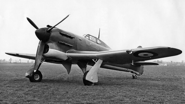
In July 1937, Hawker proposed two Camm-designed aircraft—the N-type and the R-type, named for their respective Napier and Rolls-Royce powerplants. The Air Ministry told Hawker to wait until an official request was issued, which came in March 1938 in the form of Specification F.18/37 seeking a fighter capable of 400 mph (644 km/h) at 20,000 ft (6,096 m). Hawker was notified in August 1938 that they had won the design contest for Specification F.18/37, and two prototypes of each N-type and R-type were ordered. However, an official contract was not issued until December 1938. The N-type went on to become the Sabre-powered Hawker Typhoon, while the R-type became the Vulture-powered Hawker Tornado. The two Tornado prototypes were assigned serial numbers P5219 and P5224.

The Tornado was a single-engine fighter of all-metal construction with a conventional taildragger layout. The aircraft somewhat resembled an enlarged Hawker Hurricane. From the engine to just behind the cockpit, the fuselage consisted of a tubular frame covered with aluminum panels. The rear fuselage and tail were of monocoque construction. The pilot sat in an enclosed cockpit that was accessible via side entry doors. A fairing extended behind the cockpit and limited the pilot’s rearward vision.

The Tornado’s wing was mounted to the tubular frame of the center fuselage. Because of the Vulture’s installation, the wing was mounted to the fuselage about 3 in (76 mm) lower than on the Typhoon. The wing had two main spars and consisted of an inner and outer section. The inner section had a 1.0-degree anhedral and housed the inward-retracting main landing gear. The landing gear had a wide track of 13 ft 8 in (4.17 m). A 48 US gal (40 Imp gal / 182 L) fuel tank was located in each wing between the main gear leg well and the rear spar, and a 42 US gal (35 Imp gal / 159 L) fuel tank was located in the leading edge of each inner wing section. The Tornado’s total fuel capacity was 180 US gal (150 Imp gal / 682 L). Each outer wing section had a 5.5-degree dihedral and housed six Browning .303 machine guns with 500 rpg. The thick wing was originally designed for the possible installation of six 20 mm cannons, but this configuration was never tried. Each wing had a two-section, hydraulically actuated split flap and featured a large aileron. Except for the fabric-covered rudder, all control surfaces were covered with metal.

Hawker-Tornado-P5219-rear

Another shot of the newly completed P5219 displays the aircraft’s original short tail. Note the opaque fairing behind the cockpit that blocked the pilot’s vision.

The Tornado’s Rolls-Royce Vulture II engine had 24 cylinders arranged in an X configuration. The engine was mounted to the forward part of the tubular fuselage frame and produced 1,760 hp (1,312 kW). Two rows of exhaust stacks protruded from each side of the engine’s cowling. A belly scoop between the main gear wells housed the engine’s coolant radiator and oil cooler. A door in the aft section of the scoop regulated temperatures. Two intakes between the belly scoop and the underside of the fuselage fed air to the engine’s carburetor. The engine turned a three-blade, constant-speed Rotol propeller that was 14 ft (4.27 m) in diameter.

The Hawker Tornado had a wingspan of 41 ft 11 in (12.78 m), a length of 32 ft 10 in (10.01 m), and a height of 14 ft 8 in (4.47 m). The aircraft had a top speed of 398 mph (641 km/h) at 23,000 ft (7,010 m) and stalling speeds of 82 mph (132 km/h) clean and 61 mph (98 km/h) with flaps and gear extended. The Tornado had an empty weight of 8,377 lb (3,800 kg) and a loaded weight of 10,668 lb (4,839 kg). The aircraft’s initial rate of climb was around 3,500 fpm (17.8 m/s), and its ceiling was 34,900 ft (10,638 m).

Hawker-Tornado-P5224-front

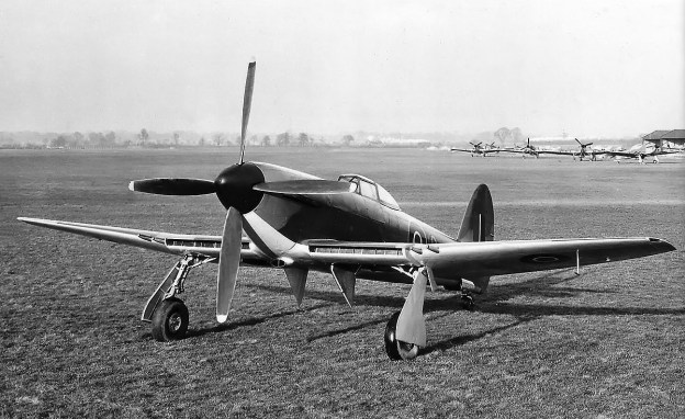
The second Tornado prototype P5224 with the chin radiator and windows behind the pilot to help improve vision. The aircraft now resembles a Typhoon, with which it shared many components.

The Tornado prototype P5219 was built at the experimental shop in Hawker’s Canbury Park Road facility in Kingston, but it was sent to Hawker’s new facility in Langley for final assembly in July 1939. The Vulture II engine was delivered in September 1939, and ground tests were started later that month. Piloted by Philip Lucas, P5219 made its first flight on 6 October 1939. During the preliminary flight tests in October and November, the aircraft achieved a speed of 370 mph (595 km/h) at 15,000 ft (4,572 m). However, the Tornado’s tail was lacking in surface area, and the rudder did not have sufficient authority to hold a straight course during takeoff and proved ineffective at speeds under 150 mph (241 km/h). Engine cooling was a constant issue, especially during ground operations. While in flight at higher speeds, turbulence from the wings disrupted airflow into the radiator, which impaired engine cooling. A new radiator was designed that would relocate the cooling system from its ventral position to a chin location under the engine. Metal was also found in the engine oil, indicating a possible issue with the Vulture’s bearings.

While the Vulture engine was undergoing maintenance, the Tornado airframe was modified with the new chin radiator and oil cooler, which shifted the aircraft’s appearance away from that of the Hurricane. In November 1939, an order for Hawker to produce 1,000 Tornados was placed. The contract was later changed to Typhoons, but then amended for 800 Typhoons and 200 Tornados, with the Tornados to be built by Avro due to Hawker’s production commitments of other aircraft, namely the Hurricane. Other Tornado production contracts were later issued, including 200 aircraft to be built by Cuncliffe-Owen and another 760 aircraft to be built by Avro. The revised Tornado took to the air on 6 December 1939, but Lucas reported that the aircraft was even more directionally unstable with the chin radiator. Performance tests in March 1940 indicated a top speed of 384 mph (618 km/h) at 20,500 ft (6,248 m), but the engine was not making full power. Various modifications were made to improve the aircraft’s stability. The exit of the radiator was extended 3 in (76 mm); the vertical stabilizer and rudder were enlarged in May 1940; and tailwheel doors were added in June 1940.

Hawker-Tornado-P5224-in-flight

P5224 in flight displaying the aircraft’s aggressive appearance and enlarged tail. Note the carburetor intake atop the engine cowling.

With stability improved, P5219 was sent to Rolls-Royce’s flight-testing facility at Hucknall to improve the engine’s performance. The aircraft was returned to Langley in mid-July 1940 with a new engine and a new Rotol propeller that was 13 ft 2.5 in (4.02 m) in diameter. Performance flight testing continued, and on 27 July, the Tornado climbed to 20,000 ft (6,096 m) in 6 minutes and 36 seconds and achieved a speed of 396.5 mph (638.1 km/h) at 20,800 ft (6,340 m). On 31 July, the Vulture engine failed in flight, and the aircraft was damaged in the subsequent forced landing.

While P5219 was being repaired, the second Tornado prototype, P5224, was flown on 7 December 1940. Construction of the second prototype was delayed by other priority war work. P5224 was built from the start with the chin radiator and an enlarged tail. The aircraft also had the carburetor intake atop the engine cowling, inner gear doors to completely enclose the main gear, and side windows behind the cockpit to improve the pilot’s vision (which was still restricted). However, engine cooling was still an issue, as were excessive vibrations with the Vulture engine.

The repaired P5219 returned to active flight testing with a 1,980 hp (1,476 kW) Vulture V engine installed by March 1941, but the future of the Vulture engine was in doubt. P5224 suffered an engine failure on 21 March 1941, and its Vulture II was subsequently replaced by a Vulture V. P5224 first flew with the Vulture V on 11 June 1941. Around June 1941, Avro was instructed to halt work on producing the Tornado fighter, and the Tornado contracts were cancelled. The Vulture engine was stalled by Rolls-Royce so they could focus on the Merlin, and the Vulture was officially cancelled in October 1941. The Sabre-powered Typhoon fighter would be produced and take over resources previously allocated to the Tornado.

Hawker-Tornado-CR-props

The first and only production Tornado, R7936, was used as a propeller testbed after its initial flight testing. The aircraft is seen here with Rotol contra-rotating propellers, which had a smaller diameter than the standard, single-rotation propellers used on the Tornado and Typhoon. Note that the aircraft did not have the windows behind the pilot like the second prototype.

P5219 continued flight testing with Hawker until at least April 1943, and the aircraft was scrapped in August 1943. P5224 was tested by the Aeroplane & Armament Experimental Establishment at Boscombe Down starting in October 1941. The aircraft was then delivered to the Royal Aircraft Establishment at Farnborough in December 1941. P5224 was scrapped in late 1944.

After the Tornado contracts were cancelled, construction of the first production Tornado, serial number R7936, was allowed to continue as well as components for two other examples that were nearing completion. R7936 was powered by a Vulture V engine and made its first flight on 29 August 1941, piloted by Lucas. In general, pilots that flew R7936 were impressed by its handling and performance. The aircraft recorded a speed of 402 mph (647 km) at 21,800 ft (6,645 m) and climbed to 20,000 ft (6,096 m) in 6 minutes and 54 seconds. With the Tornado program dead, R7936 was used as a testbed for Rotol and de Havilland contra-rotating propellers. Little information has been found on these tests, but the aircraft was delivered to Rolls-Royce in March 1942 for the installation of a Vulture engine with a contra-rotating gear reduction. The six-blade Rotol contra-rotating propeller was 11 ft 3 in (3.43 m) in diameter, and the aircraft was first flown with the unit on 11 August 1942. The de Havilland contra-rotating propellers were installed as early as December 1942. It appears R7936 continued with propeller tests until April 1944, when it was scrapped.

Hawker-Tempest-HG641-side-org

Typhoon HG641 was built to serve as a testbed for the Bristol Centaurus engine. Seen here with its original three-blade propeller, cowling, and single large exhaust manifold. The silhouette of the oil cooler can just be seen between the main landing gear.

From the first discussion with the Air Ministry before Specification F.18/37 was issued, Camm and Hawker had given some consideration to a Centaurus-powered Tornado, but little progress was undertaken beyond the preliminary design. With the Vulture and Sabre engines running into development issues by late 1940, more-serious consideration was given to installing a 2,210 hp (1,678 kW) Centaurus engine in a Tornado airframe. In September 1940, Hawker was given permission to proceed with the Centaurus-powered Tornado prototype, but the official contract was not issued until February 1941. Some work was also done on using a Wright R-3350 engine, but this design was dropped in June 1941.

The Centaurus Tornado was assigned serial number HG641. The aircraft was built by Hawker at Langley using components from uncompleted Tornado production airframes and a new center fuselage. The Centaurus engine turned a 12 ft 9 in (3.89 m) diameter, three-blade, Rotol propeller and was covered by a conventional cowling. Exhaust from the engine was expelled via a single manifold protruding from the cowling under the left side of the engine. An oil cooler was mounted between the wells for the main landing gear. The air-cooled radial reduced the aircraft’s weight by about 350 lb (159 kg). Lucas took the Centaurus Tornado up for its first flight on 23 October 1941.

Hawker-Tempest-HG641-side-mod

HG641 with the new four-blade propeller and revised cowling. The oil cooler was located in the large duct under the engine.

Initial flight tests of HG641 indicated that airflow through the oil cooler was not efficient and led to the engine running near its upper temperature limit. Even so, a speed of 378 mph (608 km/h) was recorded at 20,000 ft (6,096 m). The oil cooler was modified, and testing continued until December 1941. At that time, the aircraft was modified to improve the installation of the engine package, including exhaust and oil cooler. The cowling was revised, and a new oil cooler duct was faired into the lower cowling. Two exhaust stacks were incorporated into the left and right sides of the fairing. A four-blade propeller, also 12 ft 9 in (3.89 m) diameter, was installed, and the modified Centaurus Tornado took its first flight on 23 December 1942, piloted by Lucas. Cooling was improved, and the aircraft achieved 403 mph (649 km/h) at 22,000 ft (6,706 m) and had a ceiling of 32,800 ft (9,997 m). In February 1943, the aircraft was transferred to Bristol’s facility in Filton, where a speed of 412 mph (663 km/h) at 18,000 ft (5,486 m) was reportedly recorded. The Centaurus Tornado continued engine testing until August 1944, when the aircraft was scrapped.

The testing of Tornado aircraft provided information for developing the Typhoon fighter, contra-rotating propellers, and the Bristol Centaurus engine, which was particularly helpful when applied to the Centaurus-powered Hawker Tempest II fighter. Although the Tornado has been mostly forgotten, both the Typhoon and the Tempest served with distinction during World War II.

Hawker-Tempest-HG641-rear-mod

Side view of HG641 with the new cowling. The aircraft did not have the windows behind the pilot and used hinged doors on the landing gear to completely conceal the main wheels. This was also tried on the prototypes before switching to a separate inner door.

Sources:
The Hawker Typhoon and Tempest by Francis K. Mason (1988)
Hawker Typhoon, Tempest and Sea Fury by Kev Darling (2003)
British Experimental Combat Aircraft of World War II by Tony Buttler (2012)
Fighters Volume Two by William Green (1964)
Hawker Typhoon and Tempest: A Formidable Pair by Philip Birtles (2018)
Aircraft of the Fighting Powers Volume V by H. J. Cooper and O. G. Thetford (1944)
The Secret Years: Flight Testing at Boscombe Down 1939 – 1945 by Tim Mason (1998)
Hawker Aircraft since 1920 by Francis K. Mason (1991)

Hawker-Tempest-I-front-side

Hawker Tempest I Fighter

By William Pearce

On 24 February 1940, the Hawker Typhoon fighter prototype (P5212) made its first flight, piloted by Philip G. Lucas. The Typhoon was designed by Sydney Camm of Hawker Aircraft Limited and was intended as a high-altitude interceptor capable of 400 mph (644 km/h) at 20,000 ft (6,069 m). The British Ministry of Aircraft Production placed an order for 250 Typhoons on 8 October 1939, months before the prototype’s first flight. Flight testing revealed a number of design deficiencies and that the aircraft was not quite suited for its intended role. A major issue was that the compressibility of the Typhoon’s thick wing while diving at high speed caused some instability which made it very difficult to accurately fire the aircraft’s cannons. However, the Typhoon did show promise as a low-altitude interceptor and fighter-bomber.

Hawker-Tempest-I-front-side

An excellent view of the recently completed Hawker Tempest I at Langley. Note the wing radiators, the large propeller, and the wide track of the main landing gear. The cannons are installed in the wings. A number of newly-built Hawker Hurricanes are in the background.

In March 1941, Camm proposed an updated Typhoon design with a new wing and a more powerful Napier Sabre IV engine to improve the aircraft’s performance over that of the original Typhoon, powered by a Sabre II. This new design was initially forecasted to have a top speed of 430 mph (644 km/h) at 20,000 ft (6,096 m) but was later revised up to 455 mph (732 km/h) at 26,000 ft (7,925 m). The anticipated development time of the new fighter was decreased by utilizing many existing Typhoon components, and the aircraft had an anticipated in-service date of December 1943. Discussions continued with the Ministry of Aircraft Production, and Specification F.10/41 was issued to cover the new aircraft. On 18 November 1941, two prototypes were ordered and issued serial numbers HM595 and HM599. The aircraft was designated as the Typhoon II. An order for 100 production aircraft was placed on 24 February 1942. With detailed design work underway, it was realized that few existing Typhoon components could be used in the Typhoon II. Camm proposed that a new name should be selected for the aircraft. Eventually, in August 1942, the Typhoon II was officially renamed Tempest to reflect that is was essentially a new aircraft.

The Sabre IV engine for the Tempest was expected in December 1941, and the aircraft was to make its first flight in late March 1942. However, complications with the aircraft’s design and delays with its engine resulted in a slip of the project’s entire timeline. In March 1942, Hawker decided to finish the first prototype, HM595, with a Sabre II engine and a chin radiator as used on the Typhoon. This would allow time for the airframe to be developed while Napier finished work on the Sabre IV engine, which would be installed in the second Tempest prototype, HM599.

Hawker-Tempest-I-side-high

Side view of the Tempest I with its original framed canopy and cockpit entry door on the side of the aircraft. The tail was very similar to that of the Typhoon, and unlike the Tempest V, its area was not increased. Note the tailwheel doors.

In June 1942, the Tempest project was redefined. As previously specified, HM599 would be finished with the Sabre IV engine as the Tempest I, and HM595 would be finished with the Sabre II and chin radiator as the Tempest V. Four additional prototypes were ordered: two (LA602 and LA607) would be powered by the Bristol Centaurus radial engine as the Tempest II, and two (LA610 and LA614) would be powered by the Rolls-Royce Griffon IIB as the Tempest III. The Griffon IIB would later be replaced by the Griffon 61, at which time the aircraft would become the Tempest IV. An order for 400 production Tempest Is followed in August 1942.

The Hawker Tempest I was a single-engine fighter of all-metal construction with a conventional taildragger layout. The fuselage was made up of four sections: engine and engine mount, center fuselage, rear fuselage, and tail. The center fuselage consisted of the cockpit and forward fuselage and was comprised of a tubular frame covered with aluminum panels. The rear fuselage was of monocoque construction. The Tempest I’s tail section, which included the vertical and horizontal stabilizers, was basically the same as that used on production Typhoons. The tail’s attachment was reinforced with “fish plates,” just like those on mid-war Typhoons. One difference from the Typhoon was that the Tempest I’s tailwheel was fully retractable and concealed by gear doors. The fuselage of the Tempest I was 21 in (533 mm) longer than that of the Typhoon because the engine was moved forward to accommodate a 91 US gal (76 Imp gal / 345 L) fuel tank installed in the fuselage ahead of the cockpit. The cockpit was accessible via a side entry door, and the pilot sat under a framed canopy.

Hawker-Tempest-I-rear

Rear view of the Tempest I with its original canopy. Even though the Tempest I shared many components with the Tempest V, it looks like a different aircraft.

The Tempest I’s new semi-elliptical wing was mounted to the tubular frame of the center fuselage. The wing had two main spars and consisted of an inner and outer section. The inner section had no dihedral and housed the inward-retracting main landing gear that had been redesigned from that of the Typhoon. The landing gear had a wide track of 14 ft 11 in (4.53 m). A 34 US gal (28 Imp gal / 127 L) fuel tank was located in each wing between the main gear leg well and rear spar. Engine coolant radiators and the oil cooler were installed in the leading edge of the wing’s center section. Adjustable flaps on the underside of the wing just aft of the heat exchangers regulated coolant and oil temperatures. Each outer wing section had a 5.5-degree dihedral and housed two 20 mm Hispano Mk II cannons with 150 rpg. Each wing had a two-section, hydraulically actuated split flap and featured a large aileron. The Tempest I’s wing was approximately 5 in (127 mm) thinner at the root and 7 in (178 mm) shorter in span than that of the Typhoon and could not house all the needed fuel, which is why the fuselage tank was added. Provisions were included for the installation of a 54 US gal (45 Imp gal / 205 L) drop tank under each wing. Except for the fabric-covered rudder, all control surfaces were covered with metal.

The Tempest I’s sleeve-valve, H-24 Napier Sabre IV engine was mounted to the forward part of the tubular fuselage frame. The engine produced 2,240 hp (1,670kW) at 4,000 rpm at 8,000 ft (2,438 m) with 9 psi (.62 bar) of boost. This was some 200 hp (149 kW) more than the Sabre II used on the Typhoon. A small scoop under the engine fed air into the carburetor. The Sabre IV turned a metal, four-blade, constant-speed de Havilland propeller that was 14 ft (4.27 m) in diameter. Omitting the Typhoon’s chin radiator and relocating the cooling system in the wings gave the Tempest I a much more refined and aerodynamic look compared to the earlier aircraft.

Hawker-Tempest-I-in-flight

The Tempest I in flight with Bill Humble at the controls. The aircraft now has the one-piece bubble canopy, and its armament has been removed. Note the carburetor intake under the engine.

The Hawker Tempest I had a 41 ft (12.40 m) wingspan, was 33 ft 7 in (10.24 m) long, and was 15 ft 10 in (4.83 m) tall. The aircraft’s top speed was 466 mph (750 km/h) at 24,500 ft (7,468 m) and 441 mph (710 km/h) at 13,600 ft (4,145 m). It could climb to 15,000 ft (4,572 m) in 4 minutes and 15 seconds and had a ceiling of 37,000 ft (11,278 m). The Tempest I weighed 8,950 lb (4,060 kg) empty and 11,300 lb (5,126 kg) loaded. The aircraft’s range was 500 miles (805 km) on internal fuel and 800 miles (1,287 km) with drop tanks.

Construction of the Tempest I prototype at Hawker’s new facility in Langley, England was delayed by other war work and by the wing radiators. As previously mentioned, delivery of the Sabre IV was delayed by Napier. The Sabre II-powered Tempest V was first flown on 2 September 1942 by Lucas and gave some indication of what to expect with the Tempest I. The Sabre IV engine was delivered in November 1942, and the Tempest I underwent ground trials in February 1943. Tempest I HM599 was first flown on 24 February 1943, piloted by Lucas. Lucas found the Tempest I to have improved stability over that of the Tempest V, although pitch authority became non-existent under 110 mph (177 km/h).

A new engine was installed in early March 1943, and the aircraft returned to the air on 26 March. Two days later, Bill Humble made his first flight in the Tempest I. In late April and through May, a more developed Sabre IV engine was installed, and the Tempest I was modified with a conventional, one-piece, rearward-sliding bubble canopy. It also appears that the cannons were removed, at least temporarily, at this time. The updated Tempest I flew on 4 June, piloted by Humble. Some performance testing was done during the remainder of June. The Sabre IV engine exhibited a drastic increase in oil consumption at speeds over 3,750 rpm, and the hand-built engines seldom reached 50 hours before needing to be replaced. Despite the engine difficulties, the Tempest I was praised for its performance and handling, especially at higher altitudes.

Hawker-Tempest-I-Napier-Sabre-IV

Another image of Humble in the Tempest I. This angle illustrates the aircraft’s clean lines. The air exit gap aft of the wing radiator is somewhat visible, as are the fish plates to reinforce the tail.

Another Sabre IV engine was installed in late July 1943, and a thinner horizontal stabilizer may have been installed at this time. The Tempest I resumed flight testing in August, at which time speeds of 460 mph (740 km/h) at 25,300 ft (7,711 m) and 443 mph (713 km/h) at 13,300 ft (4,054 m) were recorded. Humble achieved higher speeds in September, which included the aircraft’s official 466 mph (750 km/h) at 24,500 ft (7,468 m) and 441 mph (710 km/h) at 13,600 ft (4,145 m). The highest recorded level speed was 472 mph (760 km/h) at 18,000 ft (5,486 m). Testing continued, but development issues with the Sabre IV engine led to further work on the Tempest I project not being covered by government contract beyond December 1943. The Tempest V with its Sabre II engine required less development, and the type took over the original order for the Tempest I.

There was still life for the Tempest I. The aircraft was fitted with a 2,420 hp (1,805 kW) Sabre V engine, and the combination was first flown on 8 February 1944 by Humble. On 12 February, an order for 700 Sabre V-powered Tempest Is was received. On 9 March, the Tempest I was damaged in a ground accident involving a Hawker Hurricane. The Tempest I was quickly repaired and resumed flying on 28 March. The Tempest I order was cut to 300 aircraft in April and then converted to the Sabre V-powered Tempest VI in May.

The Tempest I continued to serve as a Sabre V engine testbed until at least March 1945. With the Sabre V, the Tempest I recorded a speed of 462 mph (743 km/h) at 17,600 ft (5,364 m) and 444 mph (715 km/h) at 7,200 ft (2,195 m). The Tempest I’s last flight appears to have been made on 31 August 1945. On 11 September 1947, the Tempest I was struck off charge, and the aircraft was scrapped on or shortly after 27 October 1947. At least six pilots made at least 91 flights in the Tempest I, but a full account of its flight time has not been found.

Hawker-Tempest-I-in-flight-top

The Tempest I was an elegant aircraft that demonstrated excellent performance. Engine trouble and the more straightforward development of the Tempest V led to the Tempest I ultimately not being produced.

Sources:
Hawker Typhoon, Tempest and Sea Fury by Kev Darling (2003)
Tempest: Hawker’s Outstanding Piston-Engined Fighter by Tony Buttler (2011)
The Hawker Typhoon and Tempest by Francis K. Mason (1988)
Fighters Volume Two by William Green (1964)
Hawker Typhoon and Tempest: A Formidable Pair by Philip Birtles (2018)
Hawker Aircraft since 1920 by Francis K. Mason (1991)

Kyushu-J7W1-Shinden-left-rear

Kyushu J7W1 Shinden Interceptor Fighter

By William Pearce

Masayoshi Tsuruno (also spelled Masaoki) was a member of the Imperial Japanese Navy’s (IJN) Aviation Research Department. Around 1940, Tsuruno first began to investigate designs of a pusher aircraft with a canard layout. Tsuruno’s research led him to believe that such a configuration would enable an aircraft to achieve a very high level of performance. In addition, the basic configuration could be easily adapted to turbojet power if such an engine became available.

Kyushu-J7W1-Shinden-left-rear

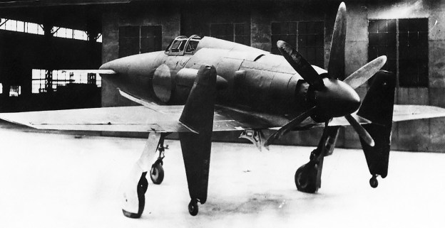
Kyushu J7W1 Shinden was an unorthodox fighter designed to intercept US bombers at high speed and high altitude. Although just two were completed, it was the only canard aircraft ordered into production during World War II. Exhaust from two cylinders flowed out the two ejector slits atop the engine cowling.

In early 1943, the IJN issued 18-Shi Otsu specification calling for a land-based fighter capable of intercepting enemy bombers. The aircraft should achieve 460 mph (740 km/h) at 28,543 ft (8,700 m), reach 26,247 ft (8,000 m) in 10.5 minutes, have a service ceiling of 39,370 ft (12,000 m), and carry four 30 mm cannons. Tsuruno worked up a design for such an aircraft and submitted it to the IJN. The IJN liked the design but was hesitant to move forward with the radical, untested configuration. Tsuruno was able to work with the First Naval Air Technical Depot (Dai-Ichi Kaigun Koku Gijitsusho) at Yokosuka to develop a proof of concept, designated MXY6.

The Yokosuka MXY6 was a glider of all wooden construction possessing a canard layout with fixed tricycle landing gear. The aircraft featured a foreplane with elevators mounted to its nose for pitch control. The swept wings were mounted to the rear fuselage, and each wing had a vertical stabilizer with a rudder mounted near its mid-point. Three of the gliders were built by Chigasaki Industry Ltd (Chigasaki Seizo KK). Piloted by Tsuruno, the MXY6’s first flight was made in January 1944. Later, one of the gliders was fitted with a 22 hp (16 kW) Nippon Hainenki Semi 11 [Ha-90] engine turning a wooden, fixed-pitch, two-blade propeller. The engine was not intended make the MXY6 fully operational under its own power, but it would enable the aircraft to sustain flight and prolong its glide. The MXY6’s flight tests indicated that Tsuruno’s design was sound. The aircraft handled well at low speeds and resisted stalling. Based on the positive preliminary tests of the MXY6, the IJN decided to proceed with Tsuruno’s 18-Shi Otsu design in February 1944. The aircraft would be built by the Kyushu Airplane Company (Kyushu Hikoki KK), and it was designated J7W1 Shinden (Magnificent Lightning).

Yokosuka_MXY6_Glider

One of the Yokosuka MXY6 gliders that survived to the end of the war and was found by US forces. The glider validated the basic configuration that was later applied to the J7W1.

Kyushu Airplane Company was founded in October 1943 as a subsidiary of the Watanabe Iron Works Ltd (Watanabe Tekkosho KK). Kyushu was selected as the manufacturer because it had both workers and production facilities that were available. Kyushu had no experience designing high-performance fighter aircraft, but the company would be aided by Tsuruno and the First Naval Air Technical Depot. An official order for the J7W1 was issued in June 1944, with the prototype’s first flight expected in January 1945.

The Kyushu J7W1 Shinden used the same layout as the MXY6, having a canard configuration with a swept, rear-mounted wing and tricycle undercarriage. The aircraft consisted of an aluminum airframe covered by aluminum panels, forming a monocoque structure. Depending on location, the panels were either flush riveted or spot welded in place. The control surfaces were skinned with aluminum. The foreplane had two spars and was mounted to the extreme nose of the aircraft at a one-degree angle of incidence. A leading-edge slat was deployed with the flaps. On the foreplane’s trailing edge was a two-section flap. The first section acted as a traditional flap that extended 26 degrees. The second section on the trailing edge acted as an elevator.

Mounted in the fuselage between the foreplanes were four 30 mm Type 5 cannons, each with 60 rounds per gun. Each cannon was 7 ft 2 in (2.19 m) long and weighed 154 lb (70 kg). The cannons were slightly staggered to allow for clearance of their respective feed belts and keep the fuselage as narrow as possible. A compartment under the cannons collected the spent shell casings because of concerns that they would strike the propeller if they were ejected from the aircraft. Two 7.9 mm machine guns with 75 rounds per gun were planned for the very front of the nose and could be used for either training or target ranging. As ranging guns, they would help ensure that the cannon shells hit the intended target and not waste the limited ammunition supply. No armament was fitted to the prototype, and ballast weight was used to simulate the cannons.

Kyushu-J7W1-Shinden-left

The wheels under the vertical stabilizers were added after the aircraft’s first flight attempt ended with bent propeller blades. Note the long landing gear’s relatively short wheel base.

Behind the cannons was the single-seat cockpit, which was covered by a rearward-sliding glazed canopy. The pilot was protected by 2.76 in (70 mm) of armored glass in the front windscreen and a .63 in (16 mm) bulkhead by the cannons. Passageways ran on both sides of the aircraft between the cockpit and outer skin. Flight controls, hydraulic lines, and wiring ran in these passageways, which were accessible via removable outer skin panels. Under and slightly behind the cockpit was a 106-gallon (400-L) self-sealing fuel tank made of .87 in (22 mm) thick rubber.

Directly behind the cockpit was a 44-gallon (165-L) oil tank, followed by a Mitsubishi [Ha-43] 42 (IJN designation MK9D) engine. The [Ha-43] was a two-row, 18-cylinder, air-cooled engine. The [Ha-43] 42 had two-stage supercharging, with the first stage made up by a pair of transversely-mounted centrifugal impellers, one on each side of the engine. The shaft of these impellers was joined to the engine by a continuously variable coupling. The output from each of the first stage impellers joined together as they fed the second stage, two-speed supercharger mounted to the rear of the engine and geared to the crankshaft. As installed in the J7W1, the engine produced 2,030 hp (1,514 kW) at 2,900 rpm with 9.7 psi (.67 bar) of boost for takeoff. Military power at 2,800 rpm and 5.8 psi (.40 bar) of boost was 1,850 hp (1,380 kW) at 6,562 ft (2,000 m) in low gear and 1,660 hp (1,238 kW) at 27,559 ft (8,400 m) in high gear.

Kyushu-J7W1-Shinden-front

The prototype was unarmed, but four 30 mm cannons, each capable of firing 500 rounds per minute, were to be mounted in the nose. The projectile from each 30 mm shell weighed 12.3 oz / 5,401 grains (350 g).

The engine was mounted in the center of the fuselage and atop the wingbox. An extension shaft approximately 29.5 in (750 mm) long extended back from the engine to a remote propeller reduction gear box. The extension shaft passed through an extended housing that was mounted between the engine and the propeller gear reduction. The gear reduction turned the propeller at .412 times crankshaft speed and also drove a 12-blade cooling fan that was 2 ft 11 in (900 mm) in diameter. A screen was placed in front of the fan to prevent any debris from exiting the rear of the aircraft and hitting either the fan or propeller. Mounted to the propeller shaft was a 11 ft 2 in (3.40 m) diameter, metal, six-blade, constant-speed, VDM (Vereinigte Deutsche Metallwerke)-type propeller built by Sumitomo Metal Industries Ltd, Propeller Division (Sumitomo Kinzoku Kogyo KK, Puropera Seizosho). The propeller had approximately 29 in (740 mm) of ground clearance with the aircraft resting on all of its landing gear. If bailing out of the aircraft was needed, the pilot could detonate an explosive cord that would sever the propeller and gear reduction.

Cooling air for the [Ha-43] engine was taken in via an oblique inlet mounted on each side of the fuselage just behind the cockpit. Flaps at the inlet’s opening were raised to decrease the flow of cooling air to the engine. Cooling air entered the inlets, passed through the fins on the engine’s cylinders, traveled along the outside of the extension shaft housing, passed through the cooling fan, and exited around the spinner or an outlet under the rear of the aircraft. Two intakes, one on each side of the aircraft, were mounted to the cooling inlet. These intakes ducted induction air through the cooling air duct and directly into the transversely mounted superchargers.

Kyushu-J7W1-Shinden-Ha-43-42-engine

The Mitsubishi [Ha-43] 42 engine installed in the J7W1 as seen post-war. The front of the aircraft is on the left. One of the two transversely-mounted, first-stage superchargers can be seen left of the engine. The oil cooler duct is in place and blocking the view of the extension shaft to the right of the engine. On the wing is the middle panel of the supercharger’s inlet scoop.

On each side of the fuselage directly behind the induction scoop was an inlet for an oil cooler. For each of the two oil coolers, after air passed through the cooler, it was mixed with the exhaust of four cylinders and ejected out a slit on the side of the fuselage just before the spinner. The ejector exhaust was used to help draw air through the oil coolers. The same philosophy applied to the exhaust from six cylinders on the bottom of the engine. These were ducted into an augmenter that helped draw cooling air through the cowling and out an outlet under the spinner. The exhaust from the remaining four cylinders, which were located on the top of the engine, exited via two outlets arranged atop the cowling to generate thrust.

The leading edge of the J7W1’s wing was swept back 20 degrees, and the trailing edge was swept back six degrees. The wings were mounted with no incidence angle. The inner wing from the wingbox to the rudder had 2.5 degrees of dihedral, and the outer wing from the rudder to the tip had zero dihedral. The structure of each wing was formed with three spars. The front spar ran along the wing’s leading edge. The center, main spar was swept back 14.5 degrees and ran in front of the main landing gear wells. A rear spar was swept forward 3.5 degrees and ran from the wingbox to just behind the main gear mount. A vertical stabilizer extended above and below the rear spar. The vertical stabilizer was mounted at approximately the midpoint of each wing and extended past the wing’s trailing edge. Initially, nothing was mounted under the vertical stabilizers, but a wheel was later added under each stabilizer to prevent propeller ground strikes. A rudder ran the entire 7 ft 3 in (2.20 m) height of each vertical stabilizer. Each wing housed a 53-gallon (200-L) fuel tank and a 20-gallon (75-L) anti-detonation fluid (water/methanol) tank for injection into the engine. Split flaps were positioned along the trailing edge of the wing between the vertical stabilizer and the fuselage. The flaps on the main wing extended 20 degrees. Two hardpoints under each outer wing could accommodate 66 or 132 lb (30 or 60 kg) bombs.

Kyushu-J7W1-Shinden-rear

Rear view of the J7W1 showing its six-blade propeller and the engine’s 12-blade cooling fan in the rear of the cowling. The exhaust augmenter outlet can be seen on the bottom of the cowling. Note the rudders extending the entire height of the vertical stabilizers.

When deployed, the legs of the main gear were angled forward more than the nose gear. This effectively extended the nose gear and caused the aircraft to sit five-degrees nose-high while on the ground. This stance minimized the rotation needed to achieve liftoff, which is very important in the pusher aircraft. The main gear was mounted forward of the vertical stabilizers. The swiveling but non-steerable nose gear retracted forward, and the main gear retracted inward. Gear retraction and extension were powered hydraulically. At approximately 5 ft 11 in (1.8 m) long, the landing gear was quite tall to allow clearance for the propeller. The gear had a fairly wide track of 15 ft (4.56 m), but the wheelbase was short at only 10 ft 2 in (3.11 m). The short wheelbase combined with the tall gear legs and the aircraft’s high center of gravity could have given the J7W1 undesirable ground handling characteristics.

The J7W1 had a 36 ft 5 in (11.11 m) wingspan, was 32 ft (9.76 m) long, and was 12 ft 10 in (3.92 m) tall. The aircraft had a top speed of 466 mph (750 km/h) at 28,543 ft (8,700 m), a cruising speed of 276 mph (444 km/h), and a stalling speed of 107 mph (172 km/h). The J7W1 could climb to 26,247 ft (8,000 m) in 10 minutes and 40 seconds and had a 39,370 ft (12,000 m) service ceiling. The aircraft had an empty weight of 7,639 lb (3,465 kg), a normal weight of 10,864 lb (4,928 kg), and a maximum weight of 11,526 lb (5,228 kg). Cruising at 9,843 ft (3,000 m) gave the J7W1 a 528-mile (850-km) range. The aircraft was stressed for a maximum speed of 575 mph (926 km/h) and 7 Gs.

Kyushu-J7W1-Shinden-front-left

The various ducts on the side of the J7W1 are illustrated in this image. The flaps to reduce cooling air can be seen just before the oblique inlet on the side of the aircraft. The smaller scoop that fed air into the supercharger is mounted to the outside of the cooling air inlet. The oil cooler inlet can be seen just behind the tapered fairing for the induction scoop.

While the prototype was still under construction, the IJN ordered the J7W1 into production in May 1944 to counter the imminent threat of American bombing raids with the Boeing B-29 Superfortress. Ultimately, the production schedule called for Kyushu to produce 30 aircraft per month, and the Nakajima Aircraft Company, Ltd (Nakajima Hikoki KK) would build 120 units per month. In June 1944, the United States Army Air Force began conducting bombing raids against Japan using the B-29. To intercept these bombers and disrupt these raids were the exact purposes for which the J7W1 was designed. In September 1944, a mockup of the J7W1 was inspected by the IJN, and wind tunnel tests of a scale model had yielded positive results.

The J7W1 was built at Kyushu’s Zasshonokuma Plant, near Fukuoka city. The airframe was nearing completion in January 1945, when the first flight was originally scheduled to be conducted. Bombing raids delayed delivery of the [Ha-43] 42 engine, which finally arrived in April. The J7W1 was finally completed on 10 June and was subsequently disassembled and moved to Mushiroda Airfield (now Fukuoka Airport) in Fukuoka city on 15 June. Reassembled, the aircraft was inspected on 19 June, but bombing raids caused some delays. Ground tests were soon conducted and indicated a tendency for the engine to overheat due to a lack of cooling airflow. Tsuruno attempted the first flight in July, but as the J7W1 began to take flight, the engine’s torque induced a roll to the right. The aircraft’s nose went high and caused the propeller tips to strike the ground, bending the tips back.

Kyushu-J7W1-Shinden-repair-right-side

Following World War II, the J7W1 was repaired and then painted before the aircraft was shipped to the United States. The new panels are easily seen in this image prior to the aircraft being repainted. Note that there is no cockpit glass.

The J7W1 was repaired, and the second prototype’s propeller was installed. A tailwheel from a Kyushu K11W Shiragiku (White Chrysanthemum) trainer was added under each vertical stabilizer so that during an over-rotation, a propeller strike would not occur again. Yoshitaka Miyaishi took over the flight tests and started over with ground runs to assess the aircraft’s handling. The J7W1 made its first flight on 3 August 1945. Liftoff occurred at 126 mph (204 km/h), and the aircraft was not flown above 1,312 ft (400 m). The speed did not exceed 161 mph (259 km/h), and the flight lasted under 15 minutes, with the aircraft landing at 115 mph (185 km/h). The J7W1’s tendency to roll to the right persisted and needed much left aileron input to correct, but the aircraft behaved reasonably well otherwise. Two further flights were made on 6 and 8 August, each about 15 minutes in length. The aircraft’s basic handling was evaluated, and the landing gear was never retracted during the tests. The roll to the right was made worse with the flaps deployed and the engine producing more torque to maintain airspeed. The J7W1 exhibited a tendency for its nose to pitch down, which was countered by a steady pull on the control stick. The engine, extension shaft, and remote gear reduction caused some vibration issues.

Modifications were contemplated to neutralize the engine’s torque reaction and correct the aircraft’s handling. A proposition was made to increase the foreplane’s angle of incidence to three degrees and change the main wing’s flap deployment to 30 degrees. In addition, the oil cooler needed to be improved. It was decided that speed tests would be initiated on the aircraft’s next flight, scheduled for 17 August. However, all work was stopped with the Japanese surrender on 15 August, and much of the aircraft’s documentation was burned on 16 August.

Kyushu-J7W1-Shinden-display

The J7W1 on display in Japan after it was repaired and painted. The inlet for the right oil cooler can be seen just behind the induction scoop, and the oil cooler’s exit can be seen right before the propeller. Note that the flaps are partially deployed.

At the end of the war, the second J7W1 was nearly complete and waiting on its [Ha-43] 42 engine, and the third aircraft was under construction. No other examples were completed to any meaningful level. The third J7W1 was planned to have the three-degree foreplane angle of incidence and a [Ha-43] 43 engine that produced an additional 130 hp (97 kW) for takeoff. This engine would have a single impeller for its first-stage, continuously-variable supercharger. The intake for the engine was moved to the inside of the J7W1’s cooling air inlets. The fourth and later aircraft would incorporate the changes from the third and also have a four-blade propeller 11 ft 6 in or 11 ft 10 in (3.5 m or 3.6 m) in diameter. The four-blade propeller had wider blades, was easier to manufacture, and was intended to cure some of the J7W1’s tendency to roll to the right. Beginning with the eighth aircraft, a 2,250 hp (1678 kW) [Ha-43] 51 engine would be installed. The [Ha-43] 51 had a single-stage, three-speed, mechanical supercharger instead of two-stage supercharging with a continuously-variable first stage.

The second and third J7W1 were both destroyed following the Japanese surrender. The first prototype, with around 45 minutes of flight time, was captured by US Marines and found to have all of the cockpit glass removed and some body panels damaged, possibly from a typhoon. For many years, it was thought that the first prototype was destroyed and that the second aircraft was captured by US forces, but this was later found to be incorrect. Under US orders, the aircraft was repaired and repainted while still in Japan. Most pictures of the J7W1 are immediately after the repairs have been made or shortly after it was painted. In almost all of the pictures, the cockpit glass is missing. In October 1945, the J7W1 was disassembled and shipped to the United States.

Kyushu-J7W1-Shinden-Tsuruno

Six US Servicemen and four Japanese dignitaries pose next to the J7W1. Masayoshi Tsuruno, the aircraft’s designer, is the fourth from the left. The men give a good indication of the aircraft’s tall stance and overall size.

The surviving J7W1 was assigned ‘Foreign Evaluation’ FE-326 (later T2-326), and attempts were made to bring the aircraft to a flightworthy status. It is believed that most of this work, including new cockpit glass and installing several American flight instruments, was conducted in mid-1946 at Middletown Air Depot (now Harrisburg International Airport) in Pennsylvania. In September 1946, the aircraft was moved to the Orchard Field Airport (now O’Hare Airport) Special Depot in Park Ridge, Illinois. Instructions indicated that the J7W1 could be made airworthy if an overhauled engine was found, but this never occurred and the aircraft was not flown in the United States. The J7W1 was transferred to the Smithsonian National Air and Space Museum in 1960. The aircraft is preserved in a disassembled and unrestored state, with the [Ha-43] 42 engine still installed in the fuselage. Amazingly, video of the aircraft’s aborted first flight attempt and eventual first flight can be found on YouTube.

Around 2016, a full-size model of the J7W1 was built by Hitoshi Sakamoto. The model was on special display at the Yoichi Space Museum in Hokkaido, but it is not known if it is still there.

A turbojet version of the aircraft had been considered from the start, but a suitable powerplant had not been built in Japan by the close of the war. Designated J7W2 Shinden-Kai, the jet aircraft most likely would have had shorter landing gear, with additional fuel tanks in the wings occupying the space formerly used by the longer gear. There is no indication that the J7W2 had progressed beyond the preliminary design phase before the war’s end.

Kyushu-J7W1-Shinden-NASM

Today, J7W1 is disassembled but fairly complete. However, the years of storage have led to many bent and dented parts. The aircraft was long stored in the Smithsonian National Air and Space Museum’s Paul E. Garber facility, but the cockpit and foreplanes are on display at the Steven F. Udvar-Hazy Center in Chantilly, Virginia. (NASM image)

Sources:
Zoukei-mura Concept Note SWS No. 1 J7W1 Imperial Japanese Navy Fighter Aircraft Shin Den by Hideyuki Shigete (2010)
Japanese Secret Projects by Edwin M. Dyer III (2009)
Japanese Aircraft of the Pacific War by René J. Francillon (1979/2000)
– “Kyushu Airplane Company” The United States Strategic Bombing Survey, Corporation Report No. XV (February 1947)
Encyclopedia of Japanese Aircraft 1900–1945 Vol. 4: Kawasaki by Tadashi Nozawa (1966)
The XPlanes of Imperial Japanese Army & Navy 1924–45 by Shigeru Nohara (1999)
War Prizes by Phil Butler (1994/1998)
https://www.secretprojects.co.uk/threads/kyushu-J7W1-shinden-J7W2-shinden-kai.16914/
https://airandspace.si.edu/collection-objects/kyushu-j7w1-shinden-magnificent-lightning

McDonnell-XP-67-top

McDonnell Aircraft Corporation XP-67 Fighter

By William Pearce

On 20 February 1940, the Army Air Corps (AAC) issued Request for Data R40-C that sought designs of new fighter aircraft capable of 450 mph (724 km/h), with 525 mph (845 km/h) listed as desirable. The AAC encouraged aircraft manufacturers to propose unconventional designs. The McDonnell Aircraft Corporation proposed four variants of its highly-streamlined Model 1 (often called Model I), the company’s first design. Each of the four Model 1 variants were powered by a different engine, and all the engines produced over 2,000 hp (1,491 kW). The Model 1’s engine was buried in the fuselage and drove wing-mounted pusher propellers via extensions shafts and right-angle gear boxes. Although not selected for R40-C, the AAC did purchase engineering data and a wind tunnel model of the design powered by an Allison V-4320 engine.

McDonnell-Model-2-original

The McDonnell Model 2 as originally proposed was similar to the Model 1 but with Continental XI-1430 engines mounted under the wings. This configuration was found to create excessive drag.

McDonnell worked with the AAC to refine the Model 1 design and submitted the Model 2 (often called Model II) on 30 June 1940. The Model 2 had a crew of two, and two wing-mounted Continental XI-1430 engines replaced the single engine in the fuselage. The aircraft retained the basic shape of the Model 1’s fuselage and wings, but the engines were initially mounted directly under the wings in a tractor configuration. The engine mounting was changed as a result of wind tunnel tests. The new configuration was to mount the engine forward of the wing with a nacelle that housed a turbosupercharger extending back past the wing’s trailing edge. The nacelle was mounted mid-wing, and this design minimized drag. To further reduce drag, the Model 2 design was modified to incorporate fairings that blended the fuselage and engine nacelles to the wings. In addition, the design had the pilot as the sole occupant. The single-seat, blended design was called the Model 2A (often called Model IIA), and it was submitted to the AAC on 24 April 1941.

On 5 May 1941, McDonnell submitted preliminary specifications of the Model 2A to the AAC. Under these specifications, the aircraft had a wingspan of 55 ft (16.8 m), a length of 42 ft 3 in (12.9 m), and a height of 14 ft 9 in (4.5 m). The Model 2A had a calculated speed of 500 mph (805 km/h) at 35,000 ft (10,668 km), 472 mph (760 km/h) at 25,000 ft (7,620 m), and 384 mph (618 km) at 5,000 ft (1,524 m). The aircraft would climb to 25,000 ft (7,620 m) in 9 minutes and have a service ceiling of 41,500 ft (12,649 m). At a cruising speed of 316 mph (509 km/h), maximum range was 2,400 miles (3,862 km) with 760 gallons (2,877 L) of internal fuel. The Model 2A had an empty weight of 13,953 lb (6,329 kg), a gross weight of 18,600 lb (8,437 kg), and a maximum weight of 21,480 lb (9,743 kg).

McDonnell-Model-2-revised

The Model 2 was revised with the engines mounted forward of the wings with streamlined nacelles mounted mid-wing. This produced a more attractive aircraft, very similar to the Model 1. However, the relation to the XP-67 is clear.

McDonnell continued to work with the AAC to refine the design of the Model 2A. On 30 September 1941, the Army Air Force (AAF—the AAC was renamed in June 1941) issued a contract to McDonnell to build two prototypes of the Model 2A interceptor pursuit fighter as the XP-67. The aircraft was assigned Materiel Experimental code MX-127. The first aircraft was scheduled to be delivered on 29 April 1943, with the second example delivered six months later on 29 October 1943. The XP-67 had a fairly conventional layout for a single-seat, twin-engine aircraft with tricycle undercarriage. What was not conventional was the extensive blending of the fuselage and engines nacelles to the aircraft’s wings to maintain true airfoil sections throughout the entire aircraft. The end result was a streamlined appearance.

The XP-67 was constructed of an aluminum frame with aluminum skin that formed a monocoque structure. All control surfaces consisted of a fabric covered aluminum frame, although aluminum skinning was later proposed for production aircraft. Effort was expended to keep the XP-67’s surface smooth and make everything flush. Initially, a door on the left side of the pressurized cockpit was to allow access. However, pressurization was dropped on the prototype, and a glazed, rearward-sliding canopy was used.

The wings had two spars, a dihedral of five degrees, and consisted of inner and outer wing sections. The outer wing section extended from the engine nacelle and was removable. Split flaps were located between the nacelle and fuselage. A small split flap existed on the outer side of the engine nacelle. The outer wing section’s trailing edge was occupied by an aileron. The ailerons drooped 15 degrees with deployment of the flaps, which had a maximum deployment of 45 degrees. However, it does not appear that the drooping ailerons were ever installed on the prototype. No hardpoints existed under the wings for bombs or drop tanks.

McDonnell-Model-2A-drawing

The Model 2A as originally proposed in May 1941 was essentially the latest Model 2 design but with large fairings that blended the fuselage and engine nacelles to the wing. This design was contracted as the XP-67.

Mounted to each wing was a liquid-cooled, Continental XI-1430 inverted V-12 engine. Initially, clockwise-rotating (right-handed) XI-1430-1 engines were to be used. In June 1942, the engines were switched to an XI-1430-17 installed on the right wing (clockwise, right-handed rotation) and an XI-1430-19 installed on the left wing (counterclockwise, left-handed rotation). Each engine of the first prototype turned a cuffed, four-blade Curtiss Electric constant-speed propeller that was 10 ft 6 in (3.2 m) in diameter. However, the cuffs were installed after the first aircraft was completed. In April 1943, McDonnell proposed installing Curtiss Electric contra-rotating propellers on the second XP-67 prototype, noting that such a change would increase the aircraft’s speed by 7–10 mph (11–16 km/h) and climb rate by 400 fpm (2.0 m/s).

The engine nacelle extended back from each engine and housed a General Electric D-23 turbosupercharger. Engine exhaust was directed straight back from the nacelle to gain some thrust. Initially, it was proposed that each engine would have a coolant radiator located in the fuselage. This was changed to each engine having two coolant radiators housed in the engine nacelle and located directly under the rear of the engine. The engine nacelles were blended into the wing, and several intakes were incorporated into the wing’s leading edge. For both engine nacelles, the intakes closest to the nacelle passed air to a cooling jacket around the exhaust manifold. The center intake directed air through the two coolant radiators per engine and to the turbosupercharger. The intakes farthest from the engine each led to an oil cooler.

An oil tank in each wing held 26 gallons (98 L) for each engine. The aircraft’s normal fuel load was 282 gallons (1,067 L), but 478 gallons (1,809 L) of additional fuel could be housed in the aircraft’s four fuel tanks located in the fuselage and wing. This brought the XP-67’s total fuel capacity to 760 gallons (2,877 L). The aircraft’s tricycle landing gear was hydraulically-powered and fully retractable. The nose wheel was swiveled, but was not steerable, and folded back into the fuselage. The main gear was mounted just inboard of the engine nacelles and folded inward. In early 1942, the AAF requested that the main gear fold into the engine nacelle, necessitating a complete redesign of the nacelles to accommodate the rearward retracting main wheels. The horizontal stabilizer had 9.55 degrees of dihedral and was mid-mounted to the aircraft’s vertical stabilizer. Like the outer wing panels, the tail was detachable for transporting the aircraft by ground. The XP-67 airframe was stressed for +8 and -4 Gs and had a diving limit of 604 mph (972 km/h) indicated.

McDonnell-XP-67-nacelle-LMAL

An XI-1430-17 with a GE D-23 turbosupercharger installed in the McDonnell XP-67 wing section for tests at the Langley Memorial Aeronautical Laboratory in September 1943. The tests were conducted to evaluate the cooling ducts of the XP-67’s radical blended design. The top image illustrates the unusual ducting of the XP-67’s nacelles, which were duplicated on the opposite side. Closest to the spinner is the exhaust manifold cooling air duct. The large middle duct was for the coolant radiator and engine intake. The outer duct was for the oil cooler. The bottom image shows the turbosupercharger, which was installed so that the exhaust provided additional thrust. Note the radiator cooling air exit duct on the landing gear door and the cuffed propellers. (LMAL images)

The XP-67’s armament changed as the aircraft was developed. Initially, the aircraft would have four 20 mm cannons with 166 rounds per gun and six .50-cal machine guns with 500 rounds per gun. The cannons would be installed on the sides of the cockpit, just behind the pilot. The machine guns were to be installed just behind the cannons. On 5 August 1941, the AAF requested that two 37 mm cannons be installed in place of two 20 mm cannons. By 16 August, the armament was revised again to six 37 mm cannons with 45 rounds per gun and no other guns. The 37 mm cannons were installed in the blended-wing’s leading edge between the cockpit and engine nacelle. The three cannons on each side of the fuselage were outside of the propeller arc. On 20 October, it was suggested that the aircraft’s design should incorporate provisions to replace four of the 37 mm cannons with four 20 mm cannons. On 8 November, it was decided that the first aircraft would have six 37 mm cannons, and the second aircraft would have two 37 mm and four 20 mm cannons.

Extensive wind tunnel tests were conducted on various XP-67 models throughout 1942 and 1943. These tests led to many minor changes in the aircraft. Much of this testing was focused on the extensive fairing used to blend the wing and fuselage. The cooling system was also carefully scrutinized with many minor changes taking place to the cooling ducts. A full-size mockup of the XP-67 was inspected in mid-April 1942, which led to more changes. The most significant changes were lengthening the aircraft’s nose by 15 in (381 mm) and changing the flight control actuation system from push-pull rods to cables. In May, a fuselage section was built to test fire the 37 mm cannons. The tests proved satisfactory, but McDonnell redesigned the 37 mm cannon installation in October, necessitating another mockup and more tests. The new 37mm cannon installation mockup successfully passed its tests in March 1944, but the armament was never installed in the prototype. On 17 June 1942, the decision was made to finish the prototype without a pressurized cockpit. In April 1943, there were discussions of cancelling the XP-67, but the aircraft was seen as a good way to test the experimental wing blending, cannon armament, and XI-1430 engines.

McDonnell-XP-67-construction

The McDonnell XP-67 nearly complete in mid-November 1943. Even though the nacelle’s duct design was found to be insufficient in the wind tunnel tests, the aircraft was not modified with a new design until later. Note the covered ports for 37 mm cannons on each side of the cockpit and that the propellers do not have their cuffs installed.

McDonnell had built a full-scale XP-67 engine nacelle for testing the XI-1430 engine installation. Tests were conducted by McDonnell starting in May 1943. After accumulating almost 27 hours of operation, the rig was sent to the National Advisory Committee for Aeronautics (NACA) at the Langley Memorial Aeronautical Laboratory (LMAL, now Langley Research Center) in Virginia. The NACA added about 17.5 hours to the engine conducting tests in August and September to analyze the installation’s effectiveness for cooling the coolant, oil, and intercooler. The tests indicated that the cooling system was insufficient. The nacelle with revised ducts was then shipped to Wright Field in Dayton, Ohio in October 1943. Wright field added another 6.5 hours to the engine, bringing the total to 51 hours. The new ducts proved satisfactory, reducing the drag of the ducts by 25 percent and improving cooling by 200 percent. However, excessive vibrations occurred between the engine and its mounting structure, necessitating a more rigid mount. McDonnell was allowed to proceeded with testing the first XP-67, although the prototype would not be changed until after its first flight when additional changes beyond the cooling system would most likely need to take place. Wind tunnel tests had indicated that the horizontal stabilizer would need to be raised by 12 in (305 mm) to improve stability. McDonnell was instructed to stop work on the second prototype until successful flight tests of the first aircraft had been conducted.

Serial number 42-11677 was given to the first XP-67, and serial number 42-11678 was given to the second prototype. Unofficially, the XP-67 was given the name ‘Moonbat’ or just ‘Bat,’ but it does not appear that an official name was ever bestowed upon the aircraft. With all the design changes since the XP-67 was initially contracted, the aircraft’s specifications had changed. The wingspan remained at 55 ft (16.8 m), but the length increased 2 ft 6 in (.8 m) to 44 ft 9 in (13.6 m), and the height increased 1 ft (.3 m) to 15 ft 9 in (4.8 m). The standard fuel load remained at 280 gallons (1,060 L), but the additional fuel load decreased by 25 gallons (95 L) to 455 gallons (1,722 L), giving a total maximum internal fuel load of 735 gallons (2,782 L). The XP-67’s weight had increased by 3,792 lb (1,720 kg), resulting in an empty weight of 17,745 lb (8,049 kg), a gross weight of 22,114 lb (10,031 kg), and a maximum weight of 24,836 lb (11,265 kg). A reduction in performance accompanied the weight increase, resulting in an estimated speed of 448 mph (720 km/h) at 25,000 ft (7,620 m), which was a 24 mph (39 km/h) reduction, and 367 mph (591 km/h) at sea level. The time to climb to 25,000 ft (7,620 m) was increased by nearly five minutes to 14.8 minutes, and the service ceiling decreased 4,100 ft (1,250 m) to 37,400 ft (11,400 m). The XP-67’s cruising speed decreased 46 mph (74 km/h) to 270 mph (435 km/h), but maximum range was little changed at 2,385 miles (3,838 km) with 735 gallons (2,782 L) of fuel.

McDonnell-XP-67-right-front

The completed XP-67 with revised nacelle cooling ducts and after the horizontal stabilizer was raised 12 in (305 mm). The most noticeable duct modification was to the exhaust manifold cooling intake, which was changed to a scoop. Note that the propellers rotated in opposite directions.

On 1 December 1943, the XP-67 had its XI-1430 engines installed and was ready for ground tests. However, both engines caught fire and damaged the aircraft on 8 December. The fires were caused by issues with the exhaust manifolds. The XP-67 was repaired and made its first flight on 6 January 1944, taking off from Scott Field in Belleville, Illinois. The flight was nearly two years later than the anticipated first flight when the XP-67 contract was originally issued. Test pilot Ed E. Elliott had to cut the flight to just six minutes due to both turbosuperchargers overheating, which resulted in small fires. During the short flight, the XP-67 exhibited good handling characteristics.

The aircraft was again repaired, with the second and third flights occurring on 26 and 28 January 1944. On 1 February, the aircraft’s fourth flight was cut short due to a main bearing failure on the left engine caused by an unintentional overspeed of the engine. The cockpit canopy also detached during the flight. While the XP-67 was down for repairs and new XI-1430 engines, the horizontal stabilizer was raised 12 in (305 mm). The cooling ducts in the engine nacelles were also modified, with the most noticeable being the exhaust shroud inlet, which was changed to more of a scoop. The updated aircraft flew again on 23 March 1944 and demonstrated improved stability, but one turbosupercharger failed at 10,000 ft (3,048 m).

In April 1944, it was reported that the engines were running too cool. The closed main gear door formed part of the air duct aft of the radiator. However, the gear doors did not seal tightly and caused an excessive amount of air to exit the duct. This resulted in too much air passing through the radiator and reducing the engine temperature below ideal levels. McDonnell was allowed to install a thermostat on the prototype to help control coolant temperatures but was also told that such issues would not be acceptable on production aircraft. Around this same time, construction of the second prototype was allowed to proceed with the exception of parts that would be affected by an engine change.

McDonnell-XP-67-top

The unusual planform of the XP-67 is illustrated in this view. The two ports in the middle of each nacelle were the forward exit for the exhaust manifold cooling air. The rear exit is denoted by the white staining at the end of the nacelle. The outer wing section was detachable just outside of the nacelle.

In May 1944, three AAF pilots flew the XP-67 and reported that the XI-1430 engines ran rough and seemed underpowered. Tests indicated that at normal power, the engines were only delivering 1,060 hp (790 kW), well below the expected 1,350 hp (1,007 kW). The XP-67 was noted for having high control forces at high speeds, exhibiting a Dutch roll indicating some directional instability, and not making a good gun platform. The maximum speed with the engines delivering 1,600 hp (1,193 kW) at 3,200 rpm was 357 mph (574 km/h) at 10,000 ft (3,048 m) and 393 mph (632 km/h) at 20,000 ft (6,096 m). From these values and other tests, McDonnell calculated that the XP-67 could attain 405 mph (652 km/h) at 25,000 ft (7,620 m) at the same power setting. Takeoff speed was 130 mph (209 km/h); the clean stall speed was 118 mph (190 km/h) with buffeting starting at 140 mph (225 km/h); and the aircraft had a high landing speed of 120 mph (193 km/h). In general, the XP-67 was found to be inferior to other fighters currently in production.

McDonnell got permission to install contra-rotating propellers on the first prototype when the engines were ready, and they were expected in June 1944. No information has been found indicating that the contra-rotating versions of the XI-1430 were delivered. In June, it was decided to install 11 ft (3.4 m) diameter four-blade Aeroproducts propellers rather than contra-rotating propellers. However, tests would continue with the Curtiss propellers until the Aeroproducts were ready. It was also noted that the XP-67 had experienced no engine fires since its fourth flight, and the aircraft had completed about 50 flights without any serious issues.

McDonnell-XP-67-in-flight

The limited flight trials of the XP-67 indicated the aircraft handled fairly well. It was noted as underpowered and slightly unstable. Overall, visibility was said to be poor, with the engine and fairing blocking most of the view to the side and rear. Formation flying would have been difficult, as the pilot was unable to see their wingtips.

In July 1944, some in the AAF felt that the XP-67 program was expensive and served no purpose. However, others felt that the aircraft was a unique platform that would allow the testing of the six 37 mm cannons. In addition, the possibility existed to install 12 .50-cal machine guns or eight 20 mm cannons. The aircraft was seen as a good test machine, even if its performance fell below what was originally specified. It was decided to complete tests on the current aircraft to assess the blended design and then consider the possibility of armament trials.

McDonnell had long sought to change the aircraft’s engines. On 19 January 1944, McDonnell proposed discarding the XI-1430s for the second prototype and using either two-stage Allison V-1710 or Rolls-Royce Merlin RM 14SM (100-series prototype) piston engines. In addition, each engine nacelle would house a Westinghouse 9.5 (J32) turbojet behind the piston engine. The mixed-power proposal was brought up again on 16 March 1944, now using an Allison V-1710-199 (F32R) piston engine and either a Rolls-Royce W2B/37 turbojet or a GE I-20 (J39) turbojet in the nacelle. With mixed power plants, the aircraft had an estimated top speed at sea level of 500 mph (805 km/h). The engine issue was discussed again in July 1944, with McDonnell now suggesting a Rolls-Royce Merlin RM 14SM piston engine paired with a GE I-20 (J39) turbojet in each nacelle. However, AAF felt that the aircraft would need a complete redesign to incorporate different piston engines with turbojets.

Since its initial design in May 1941, there were suggestions of using a modified version of the XP-67 for photo reconnaissance. In April 1942, McDonnell suggested that the aircraft’s range could be extended to 4,000 miles (6,437 km) at a cruise speed of 200 mph (322 km/h), which would be a 20-hour flight. For this, two of the 37 mm cannons would need to be omitted and six additional fuel tanks installed along with 280 lb (127 kg) of ballast in the nose. With the extra tanks, the aircraft’s internal fuel capacity was 1,290 gallons (4,883 L). This concept was not pursued at the time, but the range extension was considered later for a photo-recon role.

McDonnell-XP-67E-model

A model of the XP-67E with its bubble canopy and mixed piston / turbojet power plants. It is not clear what engines (if any) are intended to be depicted by the model, but the nacelles were extended back to house the jet engine (LMAL image).

By July 1944, it was believed that a photo-recon version of the XP-67 would have inferior performance compared to the Lockheed F-5 (P-38). However, a mixed-power version of the aircraft was seen as a possible candidate as a photo-recon aircraft. The XP-67E was designed for the photo-recon role, and it incorporated mixed power, additional internal fuel tanks, and provisions for two 150-gallon (568-L) drop tanks mounted under the aircraft’s center section. In the XP-67E design, the engine nacelles were extended back to house the GE I-20 (J39) turbojet engine. Cameras were installed in the aft fuselage, and the XP-67E was unarmed. The fuselage was mostly unchanged, but the cockpit was enclosed in a rearward-sliding bubble canopy.

The XP-67 prototype had been undergoing modifications and repairs through August 1944. Perhaps the most major change was alerting the wing dihedral from 5 degrees to 7 degrees in an attempt to increase stability. The aircraft was ready to resume flight tests in early September. On 6 September 1944, the exhaust valve rocker of the No. 1 cylinder in the XP-67’s right engine broke while the aircraft was in flight at 10,000 ft (3,048 m). Exhaust gases unable to escape the cylinder backed up into the intake manifold and caused it to fail, resulting in a fire. The fire was first noticed at 3,000 ft (914 m) as the aircraft was preparing to land. Test pilot Elliott was able to land the XP-67 and stopped it to limit the flames from spreading. However, the brake failed after Elliott exited the aircraft, and wind turned the XP-67 so that the flames blew toward the fuselage. The XP-67 was nearly burned in half and damaged beyond repair. The aircraft had a total flight time of 43 hours. This event effectively killed the XP-67 project and the XP-67E photo-recon proposal. The entire program was suspended seven days later on 13 September, and on 24 October, McDonnell was notified that the XP-67 contract was cancelled. A formal Notice of Cancellation followed on 27 October 1944. The second prototype was about 15 percent complete and was subsequently scrapped. The total cost of the XP-67 program was approximately $4,733,476.92.

McDonnell-XP-67-fire-front

The XP-67 after the fire on 6 September 1944. Once on the ground, the fire from the right engine spread to the rear fuselage and left nacelle. The rear fuselage was nearly burned through and collapsed to the ground. An inglorious end to both the XP-67 and XI-1430 programs.

Sources:
Interceptor Pursuit Airplane Twin Engine Type XP Preliminary Specifications by McDonnell Aircraft Corporation (5 May 1941)
Memorandum Report on XP-67 Airplane, AAF No, 42-11677 by Osmond J. Ritland (19 May 1944)
Final Report on the XP-67 Airplane by John F Aldridge Jr. (31 January 1946)
Case History of XP-67 Airplane by Historical Division, Air Materiel Command (23 July 1946)
USAF Fighters of World War Two Volume Three by Michael O’Leary (1986)
U.S. Experimental & Prototype Aircraft Projects: Fighters 1939-1945 by Bill Norton (2008)

Curtiss-XF14C-2-front-left

Curtiss XF14C Carrier-Based Fighter

By William Pearce

On 30 June 1941, the United States Navy, in preparation for the future of aerial combat, ordered prototypes of the Grumman F6F Hellcat carrier fighter and the F7F Tigercat heavy fighter. The Hellcat was intended to replace the F4F Wildcat and counter the Japanese Mitsubishi A6M Zero. The Tigercat was intended to out-perform and out-gun all other fighters. The Hellcat and Tigercat went on to serve with distinction for many years. Also on 30 June 1941, the Navy ordered two prototypes of the Curtiss XF14C.

Curtiss-XF14C-2-front-left

The Curtiss XF14C-2 with its contra-rotating propellers and four 20 mm cannons appears as an imposing aircraft. However, its performance did not meet expectations. Note the stagger of the cannons and the glazed, rearward-sliding canopy.

Since 1939, the Navy had been supporting the development of the 2,300 hp (1,715 kW) Lycoming XH-2470 engine. The XH-2470 was a liquid-cooled, 24-cylinder engine in a vertical H configuration. The Navy’s support for the XH-2470 was unusual, as it had a long history of exclusively using air-cooled radial engines. In addition, the Navy had no applications for the engine until the XF14C was proposed as a high-performance fighter.

The Curtiss-Wright XF14C was designed at the company’s main facility in Buffalo, New York. The two XF14C-1 prototypes ordered were assigned Navy Bureau of Aeronautics numbers (BuNo) 03183 and 03184. Most sources state that the XF14C-1 was to be powered by the XH-2470-4 engine. Lycoming documents indicate that the -4 featured contra-rotating propellers. However, some sources state the XF14C-1 had a single rotation propeller that was 14 ft 2 in (4.32 m) in diameter. The XH-2470-2 used a single rotation propeller, but no sources have been found specifically stating that this was the engine for XF14C-1.

Regardless of the exact engine model and propellers, the XF14C-1 was an all-metal, low-wing aircraft with standard landing gear and a conventional layout. The gear was fully retractable, including the tail-wheel, and the main legs had a wide track. The arrestor tail hook extended from the extreme rear of the fuselage. The outer panels of the wings had around 7.5 degrees of dihedral and folded up for aircraft storage on an aircraft carrier. The fixed wing section had a flap along its trailing edge, and the folding section had a small flap on its inner trailing edge. The rest of the folding section had an aileron along its trailing edge. Just inboard of the wing-fold was the aircraft’s armament. Initially, each wing would house three .50-cal machine guns, but this was revised to two 20 mm cannons with 166 rounds per gun.

Curtiss-XF14C-2-right-side

Side profile of the XF14C-2 illustrates the large exhaust pipe from the turbosupercharger under the aircraft. The inscription under the diving figure on the cowling reads “Coral Princess.” Note the large wheel covers and the retracted tail hook.

The XF14C-1 had a 46 ft (14.02 m) wingspan, was 38 ft 4 in (11.68 m) long, and was 14 ft 6 in (4.42 m) tall. With the wings folded, the aircraft’s span was 22 ft 6 in (6.89 m). The XF14C-1 had an estimated speed of 344 mph (554 km/h) at 3,500 ft (1,067 m) and 374 mph (602 km/h) at 17,000 ft (5,182 m). Its initial rate of climb was 2,810 fpm (14.3 m/s), and it had a service ceiling of 30,500 ft (9,296 m). The aircraft had an empty weight of 9,868 lb (4,476 kg), a gross weight of 12,691 lb (5,757 kg), and a maximum weight of 13,868 lb (6,290 kg). The XF14C-1 had a range of 1,080 miles (1,738 km) at 176 mph (283 km/h) on 230 US gallons (192 Imp gal / 871 L) of internal fuel. With two 75-US gallon (62 Imp gal / 284 L) drop tanks, range increased to 1,520 miles (2,446 km) at 164 mph (264 km).

Wind tunnel tests conducted by the Navy in October 1942 indicated that the Curtiss-provided performance specifications for the XF14C-1 were optimistic, but the program moved forward. The first airframe (BuNo 03183) was mostly complete by September 1943. However, delays with the XH-2470 left the XF14C-1 without an engine. The engine delay gives some credence to a contra-rotating version of the XH-2470 being used in the XF14C-1. A single rotation XH-2470 had passed a Navy acceptance test in April 1941, and a single rotation XH-2470 that was delivered to the Army Air Force had made its first flight in the Vultee XP-54 on 15 January 1943. With the availability of the single-rotation XH-2470 for the Army Air Force, it seems that such an engine could have been supplied to Curtiss for the XF14C-1 if that is what the aircraft needed. The Navy subsequently dropped its participation in the XH-2470 engine program, and the XF14C-1 was cancelled in December 1943.

Curtiss and the Navy negotiated to proceed with the XF14C program by changing the engine to the experimental Wright XR-3350-16. The -16 was turbosupercharged and used contra-rotating propellers. Rated at 2,250 hp (1,678 kW) at 32,000 ft (9,754 m), the 18-cylinder, air-cooled, radial engine offered a higher service ceiling than the XH-2470. This interested the Navy, as they were looking toward developing a high-altitude interceptor. With the new engine, the Curtiss aircraft became the XF14C-2 and was pushed into a high-altitude fighter role. The cancellation of the XF14C-1 terminated all work on the second prototype, BuNo 03184, which was never built.

Curtiss-XF14C-2-wings-folded

The XF14C-2’s outer wing section folded up just outside of the cannons. Note the gap around the spinner for cooling the two-row, 18-cylinder R-3350 engine and that the second set of propeller blades have cuffs to aid cooling.

BuNo 03183 became the XF14C-2 and was modified to accept the new engine. A six-blade, contra-rotating Curtiss Electric propeller with a diameter of approximately 12 ft 10 in (3.91 m) was installed on the XR-3350-16 engine. The cowling incorporated an intake scoop under the engine. Oil coolers were placed in extensions of the XF14C-2 wing roots. The turbosupercharger was installed directly behind the engine in a housing that extended back from the lower cowling. A large exhaust pipe from the turbosupercharger extended below the aircraft behind the main wheels.

The Curtiss XF14C-2 had the same 46 ft (14.02 m) wingspan as the XF14C-1 but was shorter at 37 ft 9 in (37.75 m) long and 12 ft 4 in (3.76 m) tall. The aircraft had an estimated speed of 317 mph (510 km/h) at sea level and 424 mph (682 km/h) at 32,000 ft (9,754 m). The XF14C-2’s initial rate of climb was 2,700 fpm (13.7 m/s), and it had a service ceiling of 39,500 ft (12,040 m). The aircraft had an empty weight of 10,582 lb (4,800 kg), a gross weight of 13,405 lb (6,080 kg), and a maximum weight of 14,950 lb (6,781 kg). At a cruising speed of 172 mph (277 km/h), the XF14C-2 had a range of 950 miles (1,529 km) on 230 US gallons (192 Imp gal / 871 L) of internal fuel and 1,355 miles (2,181 km) with two 75-US gallon (62 Imp gal / 284 L) drop tanks.

The XF14C-2 was first flown in July 1944 and delivered to the Navy on 2 September 1944. Testing quickly revealed that the aircraft did not meet the expected performance and offered no advantage over fighters already in service. Top speeds of only 300 mph (483 km/h) at sea level and 398 mph (641 km/h) at 32,000 ft (9,754 m) were achieved. The aircraft’s engine and propeller combination also caused a bad vibration throughout the airframe. With the XF14C-2 underperforming, no urgent need for a high-altitude fighter, and all the R-3350 production dedicated for the Boeing B-29 Superfortress and Convair B-32 Dominator bombers, the Navy cancelled the XF14C-2. The airframe was eventually scrapped. The XF14C-2 was the last piston-engine fighter built by Curtiss.

Curtiss proposed the XF14C-3 to truly fulfill the role of a high-altitude fighter. It had a pressurized cockpit and could operate at 40,000 ft. Studies of the XF14C-3 were conducted at Navy expense until early 1945, but no aircraft was built.

Curtiss-XF14C-2-front-right

The XF14C-2 had oil-coolers in the wing roots. Note the dihedral angle of the outer wing sections. The engine and propeller combination caused an unacceptable level of vibration.

Sources:
Curtiss Fighter Aircraft by Francis H. Dean and Dan Hegedorn (2007)
US Experimental & Prototype Aircraft Projects: Fighters 1939-1945 by Bill Norton (2008)
American Secret Projects 1 by Tony Buttler and Alan Griffith (2015)
To Join with the Eagles by Murry Rubenstein and Richard M. Goldman (1974)
The American Fighter by Enzo Angelucci and Peter Bowers (1987)

Latecoere 631-03

Latécoère 631 Flying Boat Airliner

By William Pearce

On 12 March 1936, the civil aeronautics department of the French Air Ministry requested proposals for a commercial seaplane with a maximum weight of 88,185 lb (40,000 kg) and capable of carrying at least 20 passengers (with sleeping berths) and 1,100 lb (500 kg) of cargo 3,730 miles (6,000 km) against a 37 mph (60 km/h) headwind. In addition, the aircraft needed a normal cruising speed of 155 mph (250 km/h). This large passenger aircraft was to be used on transatlantic service to both North and South America. Marcel Moine, head engineer at Latécoère (Société Industrielle Latécoère, SILAT) had already been working on an aircraft to meet similar goals. In late 1935, Moine had designed an aircraft for service across the North Atlantic with a maximum weight of 142,200 lb (64,500 kg). However, the design was seen as too ambitious. Moine modified the design to meet the request issued in 1936, and the aircraft was proposed to the Air Ministry as the Latécoère 630.

Latecoere 631-04

The Latécoère 631 was one of the most impressive flying boats ever built. Unfortunately, its time had already passed before the aircraft could enter service. Laté 631-04 (fourth aircraft) F-BDRA is seen here, and it was the second of the type in service for Air France. Note the configuration of the flaps and ailerons.

The Laté 630 was an all-metal, six-engine flying boat with retractable floats. The 930 hp (694 kW), liquid-cooled Hispano Suiza 12 Ydrs was selected to power the 98,860 lb (44,842 kg) aircraft, which had a 187 ft (57.0 m) wingspan, was 117 ft 9 in (35.9 m) long, and had a range of 4,909 miles (7,900 km). On 15 November 1936, order 575/6 was issued for detailed design work of the Laté 630 and a model for wind tunnel tests. This was followed by order number 637/7 for a single Laté 630 prototype on 15 April 1937. However, the Air Ministry cancelled the Laté 630 on 22 July 1937, stating that advancements in aeronautics enabled the design and construction of a larger and more capable aircraft. Construction of the Potez-CAMS 161, which was designed under the same specifications as the Laté 630, was allowed to continue.

Taking aeronautical advancements into consideration, the Air Ministry issued an updated request for an aircraft with a maximum weight of 154,323 lb (70,000 kg) and capable of transporting 40 passengers and 11,000 lb (5,000 kg) of cargo with a normal cruising speed of over 186 mph (300 km/h). To meet the new requirements, Moine and Latécoère enlarged and repowered the Laté 630 design, creating the Laté 631. In October 1937, detailed design work and a wind tunnel model of the Laté 631 were ordered. Order number 597/8 for a single prototype was issued on 1 July 1938. A Lioré et Olivier H-49 (which became the SNCASE SE.200) prototype was also ordered under the same specification as the Laté 631.

The Latécoère 631 was an all-metal flying boat with a two-step hull. The monocoque fuselage consisted of an aluminum frame covered with aluminum sheeting. The interior of the hull was divided into numerous passenger compartments and included a lounge/bar under the radio/navigation room (may have been in the nose in some configurations) and a kitchen at the rear. The cockpit and radio/navigation room were located above the main passenger compartment and just ahead of the wings. The cockpit was positioned rather far back from the nose of the aircraft. Numerous access doors were provided, including in the nose, side of the cockpit, and in the sides of the fuselage.

Latecoere 631 cockpit

The cockpit of the Laté 631 was rather spacious. Note the six throttle levers suspended above the pilot’s seat. The copilot could not reach the levers, but the flight engineer had another set of throttles. The central pylon contained the trim wheels and controls for the floats and flaps. At left in the foreground is the navigation station, and the radio station is at right.

The high-mounted wing was blended to the top of the fuselage and carried the aircraft’s six engines in separate nacelles. The wing had two main spars and a false spar. Each wing consisted of an inner section with the engine nacelles and an outer section beyond the nacelles. The outer engine nacelle on each wing incorporated a retractable float that extended behind the wing’s trailing edge. Due to interference, the float needed to be at least partially deployed before the flaps could be lowered. A passageway in the wing’s leading edge was accessible from the radio/navigation room and allowed access to the engine nacelles. Each nacelle had two downward-opening doors just behind the engine that served as maintenance platforms. A section of the firewall was removable, allowing access to the back of the engine from within the nacelle. Between the inboard engine and the fuselage was a compartment in the wing’s leading edge designed to hold mail cargo.

Originally, 1,500 hp (1,119 kW) Gnôme Rhône 18P radial engines were selected to power the Laté 631. However, the availability of these engines was in question, and a switch to 1,600 hp (1,193 kW) Wright R-2600 radial engines was made. The Gnôme Rhône 14R and the Pratt & Whitney R-2800 were also considered, but the 14R was also unavailable, and the export of R-2800 engines was restricted. Each engine turned a three-blade, variable-pitch propeller that was 14 ft 1 in (4.3 m) in diameter and built by Ratier. Later, larger propellers were used, but sources disagree on their diameter—either 14 ft 5 in or 15 ft 1 in (4.4 m or 4.6 m). It is possible that both larger diameters were tried at various times.

At the rear of the aircraft were twin tails mounted to a horizontal stabilizer that had 16.7 degrees of dihedral. All control surfaces had an aluminum frame with a leading edge covered by aluminum. The rest of the control surface was fabric covered. Movement of the control surfaces was boosted by a servo-controlled electrohydraulic system, which could be disengaged by the pilot. The slotted aileron on each wing was split in the middle and consisted of an outer and an inner section. The ailerons also had Flettner servo tabs that were used to trim the aircraft and could be engaged to boost roll control.

Latecoere 631-01 German 63-11

Laté 631-01 (F-BAHG) in German markings as 63+11. The openings for the large passenger windows existed in the airframe but were covered on Laté 631-01. The prototype aircraft was destroyed during an allied attack while in German hands on Lake Constance in April 1944.

Six wing tanks carried 7,582 gallons (28,700 L) of fuel, and each tank fed one engine. During flight, these tanks were replenished by pumping fuel from six tanks in the hull that carried 5,785 gallons (21,900 L) of fuel. The Laté 631’s total fuel capacity was 13,367 gallons (50,600 L). Each engine had its own 111-gallon (422-L) oil tank.

The Latécoère 631 had a 188 ft 5 in (57.43 m) wingspan, was 142 ft 7 in (43.46 m) long, and was 33 ft 11 in (10.35 m) tall. The aircraft had a maximum speed of 245 mph (395 km/h) at 5,906 ft (1,800 m) and 224 mph (360 km/h) at sea level. Its cruising speed was 183 mph (295 km/h) at 1,640 ft (500 m). The Laté 631 had an empty weight of 89,265 lb (40,490 kg) and a maximum weight of 163,347 lb (75,000 kg). The aircraft had a 3,766-mile (6,060-km) range with an airspeed of 180 mph (290 km/h) against a 37 mph (60 km) headwind.

Construction of the Laté 631 was started soon after the contract was issued. However, work was halted on 12 September 1939 so that Latécoère could focus on production of desperately needed military aircraft after war was declared on Germany. After the French surrender, work on the Laté 631 resumed in July 1940 but was halted again on 10 November by German order. The French and Germans negotiated over continuing work on the aircraft, which was purely for civil transportation. The Germans allowed construction to continue, and a second prototype was ordered under the same contract as the first (597/8) on 19 March 1941. The 35 Wright R-2600 engines that had been ordered were stranded in Casablanca, Morocco by the outbreak of the war in 1939. Amazingly, the hold on these engines was released, and they were delivered at the end of 1941.

Latecoere 631-02 stripes

Laté 631-02 (F-BANT) was finished at the end of the war and painted with invasion stripes for (hopefully) easy identification. The aircraft is at Biscarrosse undergoing tests, probably around the time of its first flight on 6 March 1945. Like on the prototype, the passenger windows are covered, but the windows were later added. Note the retractable float and that engine No. 5 is running.

The Laté 631-01, the first prototype, was registered as F-BAHG and completed at Toulouse, France in the summer of 1942. The aircraft was then disassembled and transported, with some difficulty, 310 miles (500 km) to Marignane in southern France. The aircraft was then reassembled for subsequent tests on Étang de Berre. The SNCASE SE.200, the Laté 631’s competitor, was built at Marignane and was nearing completion at the same time. The reassembly of Laté 631-01 was completed in October 1942, and the aircraft made its first flight on 4 November with Pierre Crespy as the pilot. Seven others, including Moine, were onboard as crew and observers. A second flight was made on 5 November, and flutter of the aileron and wing was encountered at 143 mph (230 km/h). The issues were traced to an improperly made part in the aileron control circuit that had subsequently failed.

Laté 631-01 was repaired, but German occupation of the French free zone on November 1942 brought a halt to further flight tests. On 23 November, order 280/42 was issued for two additional Laté 631s, bringing the total to four aircraft. The Germans lifted flight restrictions, and Laté 631-01 was flown again in December 1942. Test flights continued but were halted on several occasions by German orders. In April 1943, the tests were allowed to continue provided the aircraft was painted in German colors with German markings and a Lufthansa pilot was on board during the flights. Germany had essentially seized Laté 631-01 (and the SE.200) at this point and believed the aircraft could be used as a commercial transport once the “quick” war was concluded. The Germans were also interested in ways to add armament to the flying boat and make it a maritime patrol aircraft. Laté 631-01 was repainted and carried the German code 63+11 (for 631-01).

Laté 631-01 flight testing resumed in June 1943. On 20 January 1944, the aircraft took off on its 46th flight, and it was the first flight in which its gross weight exceeded 154,323 lb (70,000 kg). A second flight was made at 157,630 lb (71,500 kg). The tests had demonstrated that at 88,185 lb (40,000 kg), the Laté 631 could hold its course with three engines on the same side shut down. At 154,323 lb (70,000 kg), the course could be held with the outer two engines shut down on the same side. Some additional indications of flutter had been encountered but not understood.

Latecoere 631-02 Brazil

Laté 631-02 at Rio de Janeiro, Brazil in late October 1945. Note the open nacelle platforms, which were accessible through a wing passageway. A Brazilian flag is attached to the forward antenna mast.

Around 22 January 1944, Laté 631-01 was taken over by German forces and flown to Lake Constance (Bodensee) and moored offshore from Friedrichshafen, Germany. The SE.200 had already suffered the same fate on 17 January. On the night of 6 April 1944, Laté 631-01 and the SE.200 were destroyed at their moorings on Lake Constance by an Allied de Haviland Mosquito. The Laté 631 prototype had accumulated approximately 48 hours of flight time.

Construction of other Laté 631 aircraft had continued until early 1944, when German forces wanted Latécoère to focus on building the Junkers 488 bomber (which was never completed and was destroyed by the French Resistance). The disassembled second Laté 631 (631-02) was hidden in the French countryside until the end of the war. On 11 September 1944, order 51/44 was issued for five additional Laté 631 aircraft, which brought the total to nine. In December 1944, the components of Laté 631-02 were transported to Biscarrosse, where the aircraft was completed and assembled for testing on Lac de Biscarrosse et de Parentis. On 6 March 1945, Crespy took Laté 631-02 aloft for its first flight. While testing continued, the aircraft was christened Lionel de Marmier and was registered as F-BANT in April 1945. On 31 July, Laté 631-02 started a round trip of over 3,730 miles (6,000 km) to Dakar, Senegal, returning to Biscarrosse on 4 August. On 24 August, material for two additional Laté 631s was added to order 51/44, enabling the production of up to 11 aircraft.

On 28 September 1945, an issue with the autopilot in Laté 631-02 caused a violent roll to the right that damaged the wing, requiring the replacement of over 8,000 rivets to affect repairs. The aircraft was quickly fixed so that a scheduled propaganda flight to Rio de Janeiro, Brazil could be made on 10 October 1945. On that day, Laté 631-02 collided with a submerged concreate mooring block while taxiing and tore a 6 ft 7 in (2 m) gash in the hull. Upset over this incident, French authorities took the opportunity to nationalize the Latécoère factories. Production of the last six Laté 631 aircraft was spread between AECAT (which was formed from Latécoère), Breguet, SNCASO, and SNCAN. SNCASO at Saint-Nazaire would be primarily responsible for the production of aircraft No. 6, 8, and 10, and SNCAN at Le Havre would be primarily responsible for aircraft No. 7, 9, and 11. Laté 631-02 eventually made the flight to Rio de Janeiro, with 45 people on board, arriving on 25 October 1945.

Latecoere 631-03

Laté 631-03 (F-BANU) was the third aircraft completed. Its first flight was on 15 June 1946, and it crashed during a test flight on 28 March 1950 while investigating the loss (in-flight break up) of Laté 631-06 on 1 August 1948. Investigation of Laté 631-03’s crash revealed vibration issues with the engines and wings, and led to a solution to prevent further accidents.

On 31 October 1945, the first tragedy struck the Laté 631 program. While on a flight between Rio de Janeiro and Montevideo, Uruguay with 64 people on board, Laté 631-02 suffered a propeller failure on the No. 3 (left inboard) engine. The imbalance caused the No. 3 engine to rip completely away from the aircraft. A separated blade damaged the propeller on the No. 2 engine (left middle), which resulted in that engine almost being ripped from its mounts. Another separated blade flew through the fuselage, killed one passenger, and mortally wounded another (who later died in a hospital). An emergency landing was performed on Laguna de Rocha in Uruguay. The failure of the Ratier propeller was traced to its aluminum hub, which was subsequently replaced with a steel unit. The recovery of the aircraft was performed by replacing the missing engine with one from the right wing. The four-engine aircraft, with a minimal crew, was flown to Montevideo on 13 November for complete repairs, which took three months.

In February 1946, three Laté 631 aircraft were purchased by Argentina, but this deal ultimately fell through, with Argentina never paying for the aircraft. In May 1946, an agreement was reached in which Air France would take possession of three Laté 631 aircraft. On 15 June 1946, Jean Prévost made the first flight of Laté 631-03 at Biscarrosse. The aircraft was registered as F-BANU, christened as Henri Guillaumet, and soon transferred to Air France.

Laté 631-04 was registered as F-BDRA, and its first flight occurred on 22 May 1947 at Biscarrosse. The aircraft was the second Laté 631 to go to Air France. Laté 631-05 was registered as F-BDRB, and its first flight occurred on 22 May 1947. Laté 631-06, registered as F-BDRC, made its first flight on 9 November 1947, taking off from the Loire estuary near Saint-Nazaire, France. Laté 631-06 F-BDRC was the third aircraft for Air France.

Latecoere 631-05

Laté 631-05 (F-BDRB) first flew on 22 May 1947. The aircraft was slated to be converted into a cargo transport, but that never occurred. The aircraft was damaged beyond economical repair during a hangar collapse in February 1956.

Laté 631-07, registered as F-BDRD, made its first flight on 27 January 1948. The aircraft was lost on 21 February during a test flight from Le Havre to Biscarrosse. Laté 631-07 had taken off in poor weather and was not equipped for flying on instruments alone. It crashed into the English Channel (Bay of Seine) off Les-Dunes-de-Varreville (Utah Beach). A definitive cause was never found, but it was speculated that either the pilot lost spatial orientation and crashed into the sea, or that the pilot was flying very low or trying to land after the weather closed in and struck wreckage left behind from the D-Day landings at Utah Beach. Regardless, all 19 on board, which were the crew and Latécoère engineers, were killed.

On 1 August 1948, Air France Laté 631-06 F-BDRC was lost over the Atlantic flying between Fort-de-France, Martinique and Port-Etienne (now Nouadhibou), Mauritania. Wreckage was recovered that indicated an in-flight breakup that possibly involved a fire or explosion, but a definitive cause was never determined. None of the 52 people on board survived. F-BDRC had accumulated 185 flight hours at the time of the accident, and Air France subsequently withdrew its two other Laté 631s from service. Laté 631-04 F-BDRA participated in the search for survivors, flying a total of 75 hours, including a single 26-hour flight.

The flying boat era had ended during the 10 years between when the Latécoère 631 was ordered in 1938, and when the aircraft went into service with Air France in 1947. The advances in aviation during World War II had shown that landplanes were the future of commercial aviation. Following the accidents, there was no hope for the Laté 631 to be used as a commercial airliner. With four completed aircraft and another four under construction, the decision was made to convert the Laté 631 into a cargo aircraft.

Latecoere 631-06 Air France

Laté 631-06 (F-BDRC) made its first flight on 9 November 1947. It was the third (and final) aircraft to be received by Air France. On 1 August 1948, Laté 631-06 disappeared over the Atlantic with the loss of all 52 on board. Air France withdrew its remaining Laté 631 aircraft as a result. Note the access hatch atop the fuselage. Another hatch existed behind the wings.

On 28 November 1948, Laté 631-08 F-BDRE was flown for the first time, taking off from Saint-Nazaire. Laté 631-08 was originally intended as an additional aircraft for Air France but was orphaned after the crash of Laté 631-06. Laté 631-08, along with Laté 631-03, were eventually given to a new company, SEMAF (Société d’Exploitation du Matériel Aéronautique Français / French Aircraft Equipment Exploitation Company). SEMAF was founded in March 1949 and worked to develop the Laté 631 as an air freighter. Laté 631-08 F-BDRE was converted to a cargo aircraft by strengthening its airframe and installing a 9 ft 2 in x 5 ft 3 in (2.80 x 1.60 m) cargo door on the left side of the rear fuselage. The aircraft was first flown with the modifications on 8 June 1949. Laté 631-08 soon began hauling fabric and manufactured products between France and various places in Africa. The aircraft had completed 12 trips by March 1950.

Laté 631-09 F-BDRF preceded Laté 631-08 into the air. Laté 631-09’s first flight occurred on 20 November 1948 at Le Harve. Laté 631-10 F-BDRG made its first flight on 7 October 1949 from Saint-Nazaire. Both of these aircraft were flown to Biscarrosse and stored with the never completed Laté 631-11 F-BDRH. Laté 631-09 and -10 were later reregistered as F-WDRF and F-WDRG.

Laté 631-03 F-BANU was reregistered as F-WANU when it underwent tests to measure vibrations of the airframe and engines. This was done in part to discover what led to the loss of Laté 631-06 F-BDRC. On 28 March 1950, Laté 631-03 made its second flight of the day, taking off from Biscarrosse. With engine power pushed up, the left wing began to flutter, and the outer section of the left aileron broke away. Laté 631-03 began to spin, turned on its back, and continued to spin until it impacted the water inverted. The 12 people on board, which included the crew and engineers from Latécoère and Rotol, were killed instantly. Many witnessed the crash, and the wreckage of Laté 631-03 was recovered. Examination revealed that the engines with a .4375 gear reduction and operating at 1,925 rpm during cruise flight turned the propeller at 840 rpm. This resonated with a critical frequency of the wings, ailerons and Flettner tabs, which was 840 cycles per minute. The interaction rapidly fatigued parts in the outer aileron control system and caused them to fail. The damaged aileron system allowed the aileron to flutter, breaking the control system completely and leading to a complete loss of aircraft control.

Latecoere 631-08

Laté 631-08 (F-BDRE) is seen here with its updated registration of F-WDRE. Laté 631-08 was the only aircraft that operated as an air freighter.

At the time if the accident, Laté 631-03 had been reengined with R-2600 engines incorporating a .5625 gear reduction. These engines were installed on later Laté 631 aircraft and retrofitted on the earlier aircraft. However, nearly all of the Laté 631-03’s 1,001 hours were with the other engines, which was enough to have fatigued the aileron control to its breaking point. The loss of Laté 631-03 led to the collapse of SEMAF.

With the cause of the crash known, a new company was formed to upgrade the Laté 631 fleet and modify them for cargo service. La Société France Hydro (France Hydro Company) was given charge of Laté 631-02 and Laté 631-08, which was reregistered as F-WDRE. Modifications to prevent a reoccurrence of Laté 631-03’s crash were incorporated into the aircraft, and Laté 631-08 returned to cargo service in late 1951. Laté 631-08 flew a Biscarrosse-Bizerte-Bahrain-Trincomalee-Saigon route of some 7,460 miles (12,000 km) starting in March 1952. The aircraft departed Bizerte, Tunisia with a takeoff weight of 167,000 lb (75,750 kg), the highest recorded for a Laté 631. By 1953, Laté 631-08 was hauling cotton from Douala, Cameroon to Biscarrosse. This had proven somewhat lucrative, and a cargo-conversion of Laté 631-02 was started. Laté 631-05 was also transferred to France Hydro, but little was done with the aircraft. On 10 September 1955, Laté 631-08 broke apart during a violent thunderstorm while over Sambolabo, Cameroon. All 16 people on board were killed. The Latécoère 631 was withdrawn from service after this accident, and no further attempts were made to use the aircraft.

In February 1956, Laté 631-05, -10, and -11 were damaged beyond economical repair when the roof of the Biscarrosse hangar collapsed after heavy snowfall. All of the remaining Latécoère 631s were subsequently scrapped, most in late 1956. In 1961, the remains of Laté 631-01 and the SE.200 prototype were raised from Lake Constance by a Swiss recovery team and subsequently scrapped.

Latecoere 631-08 France-Hydro

Laté 631-08 while in service with France Hydro. The aircraft crashed in a storm on 10 September 1955; this was the last flight of any Laté 631. The remaining aircraft were later scrapped. Note the open door on the bow and the open hatch forward of the cockpit that led to a cargo hold.

Sources:
Les Paquebots Volants by Gérard Bousquet (2006)
Latécoère: Les avions et hydravios by Jean Cuny (1992)
https://aviation-safety.net/database/types/Latecoere-631/database
https://www.baaa-acro.com/crash-archives?field_crash_aircraft_target_id=Lat%C3%A9co%C3%A8re%20631%20(29691)

Piaggio P119 engine

Piaggio P.119 Experimental Fighter

By William Pearce

Founded in 1884, Piaggio was an Italian industrial firm that began making aircraft under license in 1917. In 1923, Piaggio began building aircraft of its own design, led by Giovanni Pena. In the early 1930s, Piaggio began to manufacture aircraft engines under license. In 1936, Pena left the company and was replaced by Giovanni Casiraghi. Casiraghi had previously worked for the Waco Aircraft Company in the United States for several years.

Piaggio P119 mockup

Mockup of the Piaggio P.119 in the Finale Ligure plant. Note the guns in the wing. They appear to be 7.7 mm (.303-cal), but it is not clear. Only two machine guns are in the nose.

In 1938, Casiraghi began to design a new single-seat fighter of a rather unconventional configuration. He aspired to create a fast and maneuverable fighter that utilized as many Piaggio-sourced components as possible—the aircraft, engine, and propeller were all manufactured by Piaggio. Designated as the Piaggio P.119, the fighter design was submitted to the Regia Aeronautica (Italian Royal Air Force) on 18 March 1939. While the Regia Aeronautica was busy with other projects, Casiraghi continued to refine the fighter. The experimental P.119 was not ordered until 2 June 1941.

The P.119 had a conventional layout with the exception of the engine installation. The air-cooled, radial engine was located in the fuselage, behind the pilot. An extension shaft extended from the engine, under the cockpit, and to the propeller gear reduction at the front of the aircraft. This configuration provided good pilot visibility and enabled the armament to be centrally located in the aircraft’s nose and the engine to be located at the aircraft’s center of gravity, which enhanced maneuverability.

Piaggio P119 construction

The P.119 under construction at Finale Ligure. Note the tubular-steel center section of the engine mount and the frame of the aileron awaiting its fabric covering.

The P.119 had an all-metal airframe made up of three sections. The front and rear fuselage sections had an aluminum frame covered with aluminum panels, creating a monocoque structure. The center section, which supported the engine and wings, consisted of a tubular steel frame covered with aluminum panels. The entire fuselage possessed a circular cross section. Under the conventional tail was a non-retractable tailwheel. The all-metal wings had two spars and housed the fully retractable main wheels. Large ailerons occupied the outer half of the wings’ trailing edge, with split-flaps running along the remaining trailing edge of the wing. All control surfaces had an aluminum frame and were covered with fabric. Each wing contained an 87-gallon (330 L) fuel tank, and a 90-gallon (340 L) fuel tank was located in the fuselage behind the engine.

The cockpit was placed above the wings’ leading edge and covered with a canopy that hinged to the side (some sources state the canopy slid back). However, it does not appear that the hinged canopy covering was installed. Behind the cockpit was a tubular-steel frame that supported the air-cooled radial engine and connected the aircraft’s nose section, wings, and tail section. Originally, a 1,700 hp (1,268 kW) Piaggio P.XXII engine was to be used, but delays with that engine resulted in the substitution of a 1,500 hp (1,119 kW) Piaggio P.XV. Both engines had 18 cylinders and displaced 3,237 cu in (53.0 L). A scoop located under the aircraft’s nose brought in cooling air that was distributed annularly into the cooling fins of the engine’s cylinders with baffles helping to direct the airflow. The cooling-air exited via a semi-annular line of cowl flaps set atop the fuselage. Just behind the cockpit was the engine’s intake, and the exhaust was expelled from four stacks forward of the cowl flaps. The P.119’s variable-pitch, three-blade propeller was made by Piaggio and was 10 ft 10 in (3.3 m) in diameter.

Piaggio P119 engine

Nicolò Lana in the cockpit of the P.119 preparing for an engine run. The canopy has been removed, and only two machine guns are installed in the nose. The two left-side exhaust stack openings are visible in front of the open cowl flaps.

The aircraft’s armament consisted of four 12.7 mm (.50-cal) machine guns positioned in the nose above the propeller gear reduction and a 20 mm cannon that fired through the propeller hub. The machine guns had 500–550 rpg (the number varies by source), and the 20 mm cannon had 110 rounds. Some sources state that provisions existed to install two additional machine guns in each wing with 400 rpg. However, those sources disagree on whether the guns were 7.7 mm (.303-cal) or 12.7 mm (.50-cal). A mockup of the P.119 included the wing guns, which appear to be 7.7 mm (.303-cal), but the mockup also appears to have only two nose machine guns. Images of the P.119 prototype do not indicate any provisions for wing guns. Reportedly, the prototype did not have the cannon or two of the four nose machine guns installed. Consideration was given to a ground attack version with a 37 mm cannon firing through the propeller hub, and a bomb rack under each wing and under the aircraft’s centerline.

Piaggio P119 rear

Rear view of the P.119 illustrates the aircraft’s relatively clean exterior. The aircraft is at Villanova d’Albenga, presumably before its first flight.

The Piaggio P.119 had a wingspan of 42 ft 8 in (13.0 m), a length of 31 ft 10 in (9.7 m), and a height of 9 ft 10 in (3.0 m). The aircraft had a top speed of 398 mph (640 km/h) at 22,310 ft (6,800 m) and a stalling speed of 81 mph (130 km/h). The P.119 had an empty weight of 5,886 lb (2,670 kg) and a maximum weight of 9,039 lb (4,100 kg). The aircraft had an initial rate of climb of approximately 3,077 fpm (15.6 m/s), and a climb to 19,685 ft (6,000 m) took 7 minutes and 15 seconds. The P.119’s ceiling was 41,011 ft (12,500 m), and it had a maximum range of 932 miles (1,500 km).

Some sources indicate that two P.119 prototypes were ordered and given the Matricola Militare (military registration number) of MM 496 and MM 497, with MM 496 used on the mockup and MM 497 applied to the actual prototype. It is not clear why a mockup would need a serial number, and other sources contend that MM 496 was assigned to the prototype. However, MM 496 appears to have been assigned to the Piaggio P.108C prototype four-engine transport, and the majority of sources state that MM 497 was the P.119 prototype.

Piaggio P119 painted

The P.119 undergoing an engine run. Note the scoop that brought in cooling air for the engine. The aircraft had a fairly wide-track landing gear.

The P.119 was built at Piaggio’s Finale Ligure plant in western Italy. The aircraft was completed in late 1942 and underwent ground tests in mid-November. The P.119’s first flight occurred on 19 December 1942. The aircraft was flown at Villanova d’Albenga by Nicolò Lana. The initial flight testing revealed that the P.119 suffered from engine cooling issues, requiring the cowl flaps to stay open. The open flaps slowed the aircraft and caused its nose to pitch up. Other issues included vibrations from the engine and extension shaft installation and general instability of the P.119. These issues resulted in complete flight trails not being conducted, and aerobatic maneuvers were not attempted. On 2 August 1943, the P.119 was damaged when the brakes locked up on landing, causing the aircraft to nose over. The damage was minor and mostly limited to the propeller and a wing, but the aircraft was not repaired before the Italian surrender on 8 September 1943. Problematic and difficult to fly, the P.119 subsequently disappeared and was presumably scrapped.

Piaggio P119 noseover

The P.119 after it nosed over during landing on 2 August 1943. While the aircraft has been painted, it does not appear that the canopy cover has been installed. Note the deployed split flaps, and the intake scoop behind the cockpit.

Sources:
Dimensione Cielo 3: Caccia Assalto by Emilio Brotzu, Michele Caso, Gherardo Cosolo (1972)
Volare Avanti: The History of Piaggio Aircraft by Paolo Gavazzi (2000)
War Planes of the Second World War: Fighters, Volume Two by William Green (1961)
Italian Civil and Military Aircraft 1930-1945 by Jonathan Thompson (1963)
https://web.archive.org/web/20161121220013/http://italie1935-45.com/regia-aeronautica/appareils/item/323-piaggio-p-119
https://ww2aircraft.net/forum/threads/piaggio-p-119.47582/

Supermarine Spiteful RB518

Supermarine Spiteful and Seafang Fighters

By William Pearce

In 1942, the British Royal Aircraft Establishment at Farnborough and Supermarine Aviation were working on ways to improve the Spitfire fighter. One of the main limiting factors of the aircraft was with its wing encountering compressibility at high speed. The investigation led to interest in designing a laminar flow airfoil and adapting it to an existing Spitfire airframe. In late 1942, the British National Physics Laboratory joined the effort, and Supermarine issued Specification No 470 for the new Spitfire wing in November. As designed, the new wing was 200 lb (91 kg) lighter, would increase the aircraft’s roll rate, and was expected to increase the aircraft’s speed.

Supermarine Spiteful NN660 1st prototype

The first Supermarine Spiteful prototype (NN660) consisted of new laminar flow wings mounted to a Spitfire XIV fuselage. Note the wide and shallow radiator housings under the wings and the standard canopy

A proposal was submitted to the British Air Ministry and gathered enough interest for Specification F.1/43 to be issued in February 1943, calling for a single-seat fighter with a laminar flow wing for Air Force service and provisions for a folding wing to meet Fleet Air Arm (FAA) requirements. Supermarine proceeded with the design under the designation Type 371. Originally, the aircraft was to be named Victor or Valiant, names that were previously (but temporarily) applied to advanced Spitfire models. However, the Type 371 eventually had its name changed to Spiteful. Three prototypes were ordered, and a fourth was added later.

The design of the Supermarine Spiteful was overseen by Joseph Smith. The laminar flow wing was a completely new design compared to the wing used on the Spitfire. The all-metal wing had two spars and a straight taper on the leading and trailing edges, which simplified its manufacture. The skin used was relatively thick to add rigidity and improve aileron control. Unlike with the Spitfire, the landing gear retracted inward with the main wheels being housed in the comparatively thick wing roots. The landing gear struts compressed as the gear retracted to minimize the space needed within the wing. Wide and shallow radiators for engine cooling were housed behind the main gear wells. The oil cooler was positioned behind the coolant radiator in the left wing, and the intercooler radiator was positioned in front of the coolant radiator in the right wing. The radiator housings had adjustable inlets and exit flaps. Each wing had two 20 mm cannons with 167 rounds for each inner gun and 145 rounds for each outer gun. The underside of each wing could accommodate two 300 lb (136 kg) rockets or a hardpoint for a drop tank or a bomb up to 1,000 lb (454 kg).

The all-metal, monocoque fuselage of the Spiteful was similar to that of the Spitfire. The cockpit was raised to improve the pilot’s view over the aircraft’s nose. A new, sliding bubble canopy covered the cockpit. Four fuel tanks in the fuselage, forward of the cockpit, held a total of 120 gal (100 Imp gal / 455 L), and a tank in each wing root held 10 gal (8 Imp gal / 36 L). Starting with the third prototype, a 74 gal (62 Imp gal / 282 L) fuel tank was added behind the cockpit, bringing the total internal capacity to 214 gal (178 Imp gal / 809 L). Two 108 gal (90 Imp gal / 409 L) drop tanks could be carried under the wings, or a single 204 gal (170 Imp gal / 773 L) drop tank could be mounted to the aircraft’s centerline.

Supermarine Spiteful NN664 2nd prototype

The Spiteful prototype (NN664) is considered the first true Spiteful because it incorporated the new fuselage. The aircraft was never painted. Note the standard, Spitfire F.21 tail.

The Spiteful’s Mark numbers were a continuation of those used on the Spitfire. The Spiteful F.XIV (F.14) was powered by a 2,375 hp (1,771 kW) Rolls-Royce Griffon 69 with a five-blade, single-rotation propeller. The Spiteful F.XV (F.15) was powered by the 2,350 hp (1,752 kW) Griffon 89 or 90 with a six-blade, contra-rotating propeller. Both Griffon engines had a two-stage, two-speed supercharger, and both the five- and six-blade propellers were 11 ft (3.35 m) in diameter and built by Rotol. Originally, a Rolls-Royce Merlin engine could be substituted for the Griffon if Griffon engine production was found to be lacking, but the Merlin option was dropped in mid-1944.

The Spiteful had a 35 ft (10.67 m) wingspan, was 32 ft 11 in (9.76 m) long, and was 13 ft 5 in (4.10 m) tall. The aircraft had a maximum speed of 409 mph (658 km/h) at sea level, 437 mph (703 km/h) at 5,500 ft (1,676 m), and 483 mph (777 km/h) at 21,000 ft (6,401 m). Cruising speed for maximum range was 250 mph (402 km/h) at 20,000 ft (6,096 m). The Spiteful’s stalling speed was 95 mph (153 km/h). The aircraft’s range was 564 mi (908 km) on internal fuel and 1,315 mi (2,116 km) with drop tanks. The Spiteful had an empty weight of 7,350 lb (3,334 kg), a normal weight of 9,950 lb (4,513 kg), and a maximum weight of 11,400 lb (5,171 kg). The aircraft had an initial rate of climb of 4,890 fpm (24.8 m/s) and a ceiling of 42,000 ft (12,802 m).

Supermarine Spiteful NN667 and RB523 long scoop

A comparison of the third Spiteful prototype (NN667) and the ninth F.XIV production aircraft (RB523). Both have the elongated intake scoop mounted under the engine and just behind the spinner. Note the larger tail compared to the first two Spiteful prototypes.

With other war work taking priority, it was some time before Supermarine had anything related to the Spiteful to test. A mockup was inspected in March 1944, and the aircraft’s name was changed to Spiteful around this time. A set of wings was fitted to a Spitfire XIV (serial number NN660), which became the first Spiteful prototype. The aircraft was first flown on 30 June 1944, with Jeffrey Quill as the pilot. The aircraft used the same 2,035 hp (1,518 kW) Griffon 61 engine as installed in a standard Spitfire XIV, but its performance was superior to that of a standard Spitfire XIV. However, the Spiteful also exhibited rather violent stalling characteristics compared to the fairly docile stall of the Spitfire. This was attributed to the outer wing with the aileron stalling first, which was the opposite of how the Spitfire’s elliptical wing stalled. With the Spitfire, the outer wing stalled last and enabled the ailerons to remain effective deep into the stall. On 13 September 1944, NN660 crashed while engaged in a dog-fight test with a standard Spitfire XIV. The pilot, Frank Furlong, was killed in the crash. A definitive cause was never determined, but it was believed that the aileron control rods became jammed during moderate G maneuvers.

On 8 January 1945, the second Spiteful prototype (NN664) took to the air, piloted by Quill. The aircraft incorporated updated aileron controls and the new Spiteful fuselage. However, NN664 had a tail similar to that used on the Spitfire F.21. Extensive handling tests were undertaken on NN664 that resulted in a few changes. The most significant change was a redesigned tail with its vertical stabilizer and rudder area increased by 28 percent and its horizontal stabilizer and elevator area increased by 27 percent. NN664 first flew with the new tail on 24 June 1945, and the aircraft was sent to the Aeroplane and Armament Experimental Establishment (A&AEE) at RAF Boscombe Down for flight trials.

Supermarine Spiteful RB515 underside

The underside of Spiteful RB515, the first production aircraft, illustrates the wings’ straight leading and trailing edges. Note the standard, short intake scoop. Outlines of the radiator housing doors are visible.

Shortly after NN664’s first flight, the Air Ministry ordered 650 Spiteful aircraft. The order went through a number of reductions, including the cancellation of 150 Spitefuls around 5 May 1945 so that a comparable number of Seafangs (see below) could be ordered. The fourth prototype was included in these cancellations.

The third Spiteful prototype (NN667) was sent to the A&AEE for service evaluations on 1 February 1946. It was found that the aircraft exhibited several areas of poor build quality, and there were numerous concerns with its ease of serviceability. A multitude of fasteners needed to be undone in order to remove the engine cowling, and rearming the aircraft was a time-consuming process that involved disconnecting the controls to the ailerons. A number of modifications and improvements were suggested, but it is not clear just how many were implemented. For at least part of its existence, NN667 had an elongated air intake that would be featured on the Seafang (see below). Other Spitefuls also had the longer scoop (at least RB517, RB518, RB522 and RB523).

The first production Spiteful F.XIV (RB515) made its first flight on 2 April 1945, with Quill in the pilot’s seat. The aircraft originally had an F.21 tail, but a larger Spiteful tail was installed after RB515’s third flight, which ended in a forced landing. The aircraft’s first flight with the new tail was on 21 May 1945. On 27 September 1945, RB515 suffered an engine failure and made another forced landing at Farnborough. The damaged aircraft was subsequently written off.

Supermarine Spiteful RB515 in flight

Another view of RB515 illustrates the larger Spiteful tail that was later applied to the Spitfire F.22 and F.24. The tail improved the Spiteful’s handling, but the aircraft’s stall was still violent compared to the Spitfire’s.

Spiteful RB518 was fitted with a rounded Seafang (see below) windscreen and a 2,420 hp (1,805 kW) Griffon 101 engine to become the sole Spiteful F.XVI (F.16). The Griffon 101 had a two-stage, three-speed supercharger and turned a five-blade, single rotation propeller. In 1947, RB518 achieved 494 mph (795 km/h) at 27,800 ft (8,473 m), the highest level-flight speed recorded by a British piston-powered aircraft. Testing of this aircraft with not-fully-developed engines resulted in seven forced landings—the last was at Chilbolton in March 1949 and resulted in the landing gear being pushed through the wings. The aircraft was then dropped by the recovery crane, ending any hope of repair.

By February 1946, the Spiteful order had been reduced to 80 aircraft. This was again reduced on 22 May 1946 to 22 aircraft, and the Spiteful order finally dropped to 16 aircraft on 16 December 1946. The production order basically covered the aircraft that had been built, although some of the last aircraft may not have flown. A 17th Spiteful, RB520 (the sixth production aircraft), was handed over to the FAA for Seafang (see below) development on 22 September 1945. The aircraft was modified for carrier feasibility trials with a “stinger” arrestor hook incorporated into a special housing below the rudder. RB520 retained the standard, non-folding Spiteful wings.

Supermarine Spiteful RB518

Powered with a two-stage, three-speed Griffon 101 engine, Spiteful RB518 achieved a level-flight speed of 494 mph (795 km/h), the highest recorded by a British piston-powered aircraft. RB518 was the only F.XVI Spiteful and was subsequently written off after its seventh forced landing.

The production aircraft were serialed RB515 to RB525, RB527 to RB531, and RB535. The final Spiteful was delivered on 17 January 1947. Of the three Spiteful prototypes and 17 production aircraft, most were sold for scrap in July 1948. It appears RB518 was the last Spiteful to fly, and no examples of the type survive. The larger “Spiteful tail” was incorporated into the last Spitfires, the F.22 and F.24.

The Spiteful’s cancellation was based on a number of realities including the more impressive performance of jet aircraft, the end of World War II, and serviceability questions about the Spiteful. While the Spiteful’s speed was impressive, it was below the 504 mph (811 km/h) that was originally estimated. Furthermore, the performance of the aircraft’s laminar wing decreased substantially if there were imperfections, including smashed bugs, on the leading edge. It was unlikely that an in-service warplane would be free of all imperfections.

Supermarine Spiteful RB520

Spiteful RB520 was loaned out for Seafang development and is considered by some as a Seafang prototype. Note the tail hook housed below the rudder and the “Royal Navy” stenciling on the fuselage.

Back in October 1943, Supermarine designed the Type 382, which was basically a navalized Spiteful. The design had started with mounting a Spiteful-type, laminar flow wing on a Seafire XV. Little official interest was given to the project until 21 April 1945, when the Air Ministry issued Specification N.5/45 for a single-seat fighter for the FAA. Subsequently, Supermarine was awarded a contract for two prototype Type 382 fighters, which became the Seafang. An order for 150 Seafang aircraft was placed on 7 May 1945; this order was essentially a reallocation of Spiteful aircraft that had been cancelled around two days prior.

The production Seafang closely matched the Spiteful but incorporated wings designed so that the last four feet folded vertically. The folding mechanism was hydraulically-powered. The Seafang had an elongated carburetor intake scoop, with the opening just behind the propeller. The aircraft also had a rounded front windscreen rather than the flat plate used on the Spiteful. Under the rudder was a stinger tail hook for catching the arresting cables on the carrier deck. The Seafang’s landing gear was re-enforced to handle carrier operations. The fuel tank behind the cockpit was reduced to 54 gal (45 imp gal / 205 L), resulting in a total internal capacity of 193 gal (161 Imp gal / 732 L).

Supermarine Seafang VG471 front

The first production Supermarine Seafang F.31 (VG471) was essentially a Spiteful with arrestor gear. All F.31 aircraft had standard, non-folding wings. Note what appears to be a wide-cord propeller.

Like the Spiteful, two Seafang variants were planned. The F.31 used the 2,375 hp (1,771 kW) Griffon 69 engine with a five-blade, single-rotation propeller, while the F.32 used the 2,350 hp (1,752 kW) Griffon 89 with a six-blade, contra-rotating propeller. The F.31 was basically a Spiteful with an arrestor hook and did not incorporate folding wings. The F.31s would serve as a test aircraft while the F.32 was being developed.

The Supermarine Seafang had a 35 ft (10.67 m) wingspan, was 34 ft 1 in (10.39 m) long, and was 12 ft 7 in (3.84 m) tall. With wings folded, the span was reduced to 27 ft (8.23 m). The aircraft had a maximum speed of 397 mph (639 km/h) at sea level, 428 mph (689 km/h) at 5,500 ft (1,676 m), and 475 mph (764 km/h) at 21,000 ft (6,401 m). Cruising speed for maximum range was 250 mph (402 km/h) at 20,000 ft (6,096 m). The aircraft’s range was 393 mi (632 km) on internal fuel. The Seafang weighed 8,000 lb (3,629 kg) empty, 10,450 lb (4,740 kg) with a normal load, and 11,900 lb (53,98 kg) maximum. The aircraft had an initial rate of climb of 4,630 fpm (23.5 m/s) and a ceiling of 42,000 ft (12,802 m).

Supermarine Seafang VG471

The side view of Seafang VG471 illustrates many of the aircraft’s features: long intake scoop, straight wing edges, radiator scoop doors, rounded windscreen, bubble canopy, large tail, and arrestor hook.

As previously mentioned, some Spitefuls had the long intake carburetor scoop; RB518 had a Seafang windscreen; and RB520 was fitted with an arrestor hook (resulting in some sources classifying it as a Seafang prototype). This was all done to lead up to Seafang F.31 production aircraft, which were basically Spitefuls with arrestor hooks. The first Seafang F.31 was VG471, which followed the fifth Spiteful off the production line. All of the F.31s had the five-blade propeller, lacked folding wings, and would end up the only production Seafangs that were completed. VG471 was first flown in early January 1946 and used in arrestor hook trials. The original hook installation proved to be weak, and a redesigned system was installed in March 1946. The aircraft passed the trials on 1 May.

The prototype Seafang F.32s were serial numbers VB893 and VB895, and both had contra-rotating propellers and folding wings. VB895 was first flown in early 1946 and was delivered to the A&AEE on 30 June. In August 1946, VB895 was demonstrated separately to the Royal Netherlands Navy, French representatives, and United States representatives in an attempt to sell the Seafang to allies. However, no orders were placed. In May 1947, test pilot Mike Lithgow successfully performed deck trials in VB895 on the HMS Illustrious. The aircraft’s wide track landing gear drastically increased its stability while on the ground, and the contra-rotating propeller eliminated the torque effect. VB895 was also tested with a single, fuselage-mounted 204 gal (170 Imp gal / 773 L) drop tank, and the aircraft was used for armament trials. During a static test firing of the cannons on 18 May 1948, a build-up of gases in the left wing resulted in an explosion that damaged the wing. Extra vents were added, and no further issues occurred.

Supermarine Seafang VB895

The Seafang F.32 prototype VB895 was the first fully-navalized aircraft of the series. The contra-rotating propellers eliminated the torque effect that led to the downfall of many aviators, especially when operating from the short deck of an aircraft carrier.

While praised for its handling and responsiveness, the Seafang did not offer any real advantage over the Seafire 47, and the Seafang’s stall was certainly a disadvantage. An order was subsequently placed for the Seafire. The original interest in the Seafang was based on doubts regarding the suitability of jet aircraft for carrier operations. As those doubts faded, so did interest in the Seafang, and the aircraft was cancelled. A few Seafangs were kept active for a brief time to continue evaluating the laminar flow wing, which was used on the Supermarine Type 392 Attacker. The Attacker was often referred to as a “Jet Spiteful,” although it had Seafang folding wings with the radiators removed and additional fuel tanks installed. The Attacker first flew on 27 July 1946, and it was the first jet fighter to enter operational service with the FAA.

Eighteen production Seafangs were built, carrying serial numbers VG471 to VG490. The first 10 aircraft were F.31s, and the remaining eight were F.32s. However, only the first eight or so aircraft were completed, with the remaining units delivered disassembled. Sadly, like the Spiteful, all of the Seafang examples were scrapped.

Note: The Royal Air Force and Fleet Air Arm used Roman numerals for mark numbers up thorough 1942. From 1943 through 1948, the Roman numerals were phased out for new aircraft, and Arabic numerals were applied. From 1948 onward, Arabic numerals were used exclusively. The Spitefuls were typically referred to using Roman numerals, but the slightly later Seafang used Arabic numerals. The use of both Roman and Arabic numerals in this article refers to the most common use applied for the particular aircraft type.

Supermarine Seafang VB895 wings folded

The folding wings on Seafang VB895 were hydraulically operated and decreased the aircraft’s wingspan by 8 ft (2.4 m). Although, the wide tack landing gear contributed to snaking at low speeds, it enhanced the stability at higher speeds and as the aircraft slammed down on a carrier deck.

Sources:
Spitfire: The History by Eric B. Morgan and Edward Shacklady (2000)
British Experimental Combat Aircraft of World War II by Tony Buttler (2012)
Supermarine Aircraft since 1914 by C.F. Andrews and E.B. Morgan (1981)
Ultimate Spitfires by Peter Caygill (2006)
Supermarine Fighter Aircraft by Victor F. Bingham (2004)
Griffon-Powered Spitfires by Kev Darling (2001)
Fighters: Volume Two by William Green (1961)
Interceptor Fighters for the Royal Air Force 1935–45 by Michael J.F. Bowyer (1984)
Spitfire: A Complete Fighting History by Alfred Price (1992)
Wings of the Weird & Wonderful by Captain Eric Brown (2012)