
By William Pearce
In the late 1930s, Baldwin Locomotive Works (Baldwin) of Eddystone, Pennsylvania sought a partner to support the design of an experimental, rigid-frame, duplex, 4-4-4-4 locomotive. With this wheel arrangement, the engine would have a four-wheel leading truck, two independent sets of four-wheel drivers, and a four-wheel trailing truck. As a duplex engine, each of the four-wheel drivers would be powered by a pair of separate cylinders. Baldwin’s Chief Engineer Ralph P. Johnson believed the newly designed engine would be capable of improved efficiency that would rival diesel locomotives, which were just beginning to outperform steam. Compared to an articulated locomotive, a rigid-frame duplex arrangement created a comparatively light engine well-suited for high speeds. In addition, having four smaller cylinders with a reduced piston speed decreased wear and maintenance compared to two larger, harder-working cylinders as used in a standard locomotive layout, such as a 4-8-4. If not well-balanced, the reciprocating and revolving forces of the drive wheels on powerful two-cylinder locomotives could actually damage the track, an issue that was alleviated with a four-cylinder duplex.
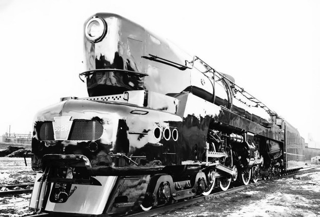
The T1 prototype, engine No. 6110, shortly after its completion by Baldwin in April 1942. The taper for the pointed nose extended much farther back than on the production engines. The front of the locomotive was enclosed with skirting, and casings extended the length of the engine, covering the top of the drive wheels. Note the gold accents and lettering.
Baldwin had just collaborated with the Pennsylvania Railroad (PRR) in creating the S1, which was finished in January 1939. The S1 was an experimental, rigid-frame, duplex locomotive with a 6-4-4-6 wheel arrangement. Designed to haul a 1,200-ton (1,089-t) passenger train at 100 mph (161 km/h), the very long S1 was PRR’s experimental trial with a duplex locomotive, and the company was interested in Baldwin’s new design. On 26 June 1940, PRR ordered two prototypes of Baldwin’s engine, but specified that it needed to use poppet valves and that the second prototype would be fitted with a booster engine on its trailing truck. PRR designated the prototype engines as the T1 class, and gave them engine numbers 6110 and 6111. Incidentally, the T1 prototypes were ordered before the S1 had entered regular service.
Starting in 1938, PRR had been experimenting with poppet valves in an effort to improve efficiency and increase power compared to the typical piston spool valve. In a standard Walschaerts valve gear, a piston spool valve was mounted in a valve chest above the double-acting cylinder. The spool valve slid back and forth, allowing steam to enter one side of the double-acting cylinder while simultaneously opening the other side to exhaust the previous steam charge. The steam flowed from the center of the valve chest into the front of the cylinder, pushing the piston back to the rear of the cylinder. The valve then slid rearward to direct steam into the rear part of the cylinder and allow the front part of the cylinder to exhaust. Steam entering the rear part of the cylinder pushed the piston forward, returning it to its original position. The efficiency of the design was limited since the admission and exhaust were both controlled by the single piston spool valve.
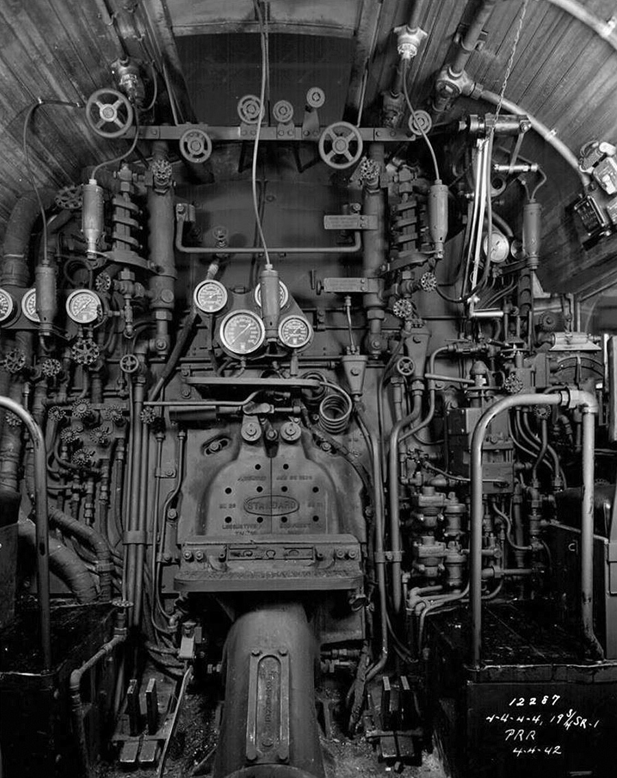
A glimpse inside of the cab of No. 6110 reveals the complex and utilitarian controls of even the most advanced steam engine. Image the heat, wind, soot, vibration, and sound of the locomotive under full steam at 100 mph (161 km/h).
With the Type A poppet valve system made by Franklin Railway Services Inc (Franklin), separate intake (admission) and exhaust valves opened to respectively allow the fresh steam charge into the cylinder and expel the spent charge after it acted on the piston. The head of these valves resembled a spoked wheel, the “hub” of which was mounted to the valve stem. When closed, the upper and lower rims of the head sealed against two separate seats. When open, steam flowed around the head and also flowed nearly unobstructed through the “spoked wheel” center of the head. The poppet admission and exhaust valves on the locomotive were independently controlled, allowing for different timing of when the valves opened and different durations of how long the valves were open. This flexibility enabled the most efficient flow of steam throughout all the various speeds the engine was traveling. PRR had installed poppet valves on a 4-6-2 K4 (No. 5399) locomotive and recorded an increase in power while operating at 80 mph (129 km/h) and above of over 40 percent.
The PRR T1 was a duplex locomotive that utilized a 4-4-4-4 wheel arrangement and was designed to haul 880 trailing tons (798-t) at 100 mph (161 km/h). PRR envisioned using the engines to haul express passenger trains on the 713-mile (1,147-km) route between Harrisburg, Pennsylvania and Chicago, Illinois. PRR anticipated that the T1 would replace its aging fleet of K4 engines.
The T1 used a four-wheel leading truck with 36 in (.91 m) wheels positioned at the front of the engine under the smokebox. A set of four 80 in (2.03 m) drive wheels followed, trailed by another nearly-identical set of four drive wheels. A four-wheel trailing truck with 42 in (1.07 m) wheels was positioned at the rear of the engine under the cab. To aid traction, sand carried in sand boxes could be deposited on the rails just ahead of the front drive wheels of each set. The two trucks and two sets of drive wheels were mounted in roller bearings to a single-piece frame bed made of cast steel by General Steel Castings in St Louis, Missouri. The cylinders and their valve chests were integrally cast with the frame, which was over 60 ft (18.29 m) long.

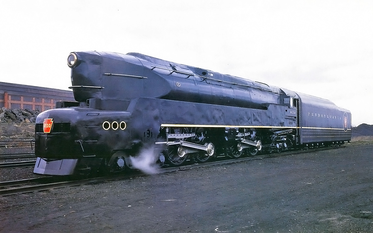
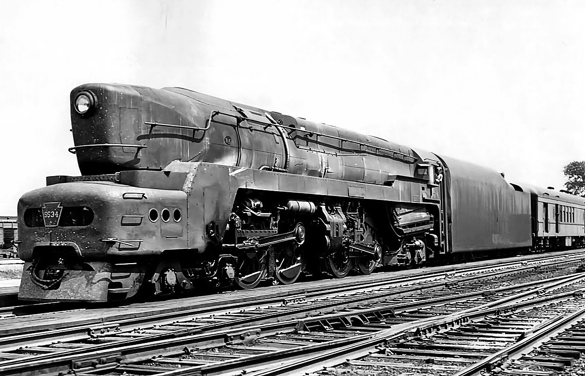
The second T1 prototype, No. 6111, displaying its unique styling done by Raymond Loewy. This engine was equipped with a booster engine, which was not included on any of the production locomotives.
The T1 was made up of a 68 ft 2.5 in (20.79 m) long engine and a 53 ft 9.5 in (16.40 m) long tender that carried the locomotive’s coal and water. This gave the complete engine an overall length of 122 ft 10 in (37.43 m). The Class 180 P 76 tender was supported by two eight-wheel trucks with 36 in (.91 m) wheels. It carried 82,000 lb (37,195 kg) of coal in a front compartment and 19,500 gallons (73,816 L) of water in a rear compartment. When combined with the 497,200 lb (225,526 kg) engine, the 433,000 lb (196,406 kg) tender gave the T1 a total weight of 930,200 lb (421,932 kg). The locomotive was 15 ft 6 in (4.72 m) tall and 11 ft 1 in (3.38 m) wide.
An HT type mechanical stoker auger transported coal from the tender to the engine’s firebox. The firebox was 138 in (3.51 m) long and 96 in (2.44 m) wide. Coal was burned in the firebox at around 2,000 °F (1,093 °C). Heat from the firebox flowed through the boiler via 184 tubes that were 2.25 in (57.2 mm) in diameter and 69 flues that were 5.5 in (139.7 mm) in diameter. Each of the tubes and flues was 18 ft (5.50 m) long. The 253 tubes and flues would stretch for 4,554 ft (1,388 m) if laid end to end. The boiler was made from approximately 1 in (254 mm) thick nickel steel. After passing through the tubes, the soot, embers, smoke, and heat from the burning coal flowed into a smokebox at the front of the engine and was subsequently vented into the atmosphere via dual vertical stacks that were approximately 20 in (508 mm) in diameter. Spent steam from the cylinders was directed through the smokebox and helped create the draft that drew air into the firebox, through the tubes, and out the stacks.
Altoona-built No. 5518 looking fairly fresh from the factory with its original front and skirting. The styled skirting was a holdover from the prototypes and was later removed to facilitate maintenance.
The tubes, flues, and firebox of the T1 had a combined evaporative surface area of 4,218 sq ft (391.9 sq m). Heat radiating from these surfaces turned water in the boiler to steam and built up a working pressure of 300 psi (20.7 bar). With a temperature of over 420 °F (215 °C), the wet, saturated steam was collected from a steam dome above the boiler. The steam then flowed to the Type A superheater, which had a surface area of 1,430 sq ft (132.8 sq m). From the superheater, small superheater elements (tubes) took the wet steam back into the flues. The steam inside the superheater elements was heated well above its saturation value and converted to dry, superheated steam. The superheater elements delivered the dry steam to the steam chamber in the superheater.
Mounted horizontally in a steam chest above each end of each cylinder were two 5.0 in (127 mm) admission valves and two 6.0 (152 mm) in exhaust valves, giving the T1 32 valves in total. All the valves for each cylinder were controlled by an oscillating camshaft mounted transversely above the center of the cylinder. The camshaft lifted the admission valve 1.0 in (25 mm) and the exhaust valve 1.25 in (32 mm). The admission valves allowed steam to enter the front side of the double-acting cylinder and fill its 7,965 cu in (130.5 L) volume, pushing the 19.75 in (558.8 mm) diameter piston back 26 in (660.4 mm) to the rear of the cylinder. The exhaust valves at the front of the cylinder opened to let out the spent charge while the admission valves at the rear of the cylinder let in a fresh charge. The steam then pushed the piston forward to its original position. The cylinder had a smaller return volume of 7,557 cu in (123.8 L) because the 4.5 in (114 mm) diameter piston rod occupied some space. The piston rod extended straight back from the cylinder and was attached to the connecting rod via a crosshead. The connecting rod linked the piston rod to the rear driving wheel in the two-wheel set on each side of the engine. Here, the connecting rod was attached to the coupling rod, which connected the two driving-wheels together. The reciprocating parts for each four-wheel driving set were supported with roller bearings and weighed 1,992 lb (904 kg). An 88-point forced lubrication system was included to keep the locomotive’s moving parts in good working order.

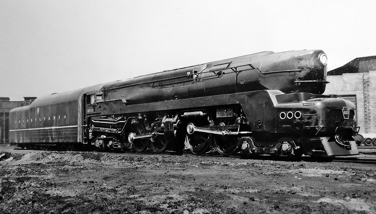
No, 5518 later in life than the above image. The skirting at the front of the engine has been removed, and stairs have replaced the foot and hand holds. The number plate keystone was moved from the front grille to under the headlight, and a new light was added to the grille. Note the shape of the valve chests above the cylinders. The two admission valves were positioned above, and were flanked by, the exhaust valves.
The T1 engine developed around 6,550 indicated hp (4,884 kW) at 85 mph (137 km/h), with a maximum recorded output of 6,665 hp (4,970 kW). The engine had a maximum tractive effort of some 64,650 lbf (287.58 kN) based on an 85 percent efficiency factor. Without any slip, each rotation of the drive wheels moved the engine 20 ft 11 in (6.38 m). At 100 mph (161 km/h), each drive wheel rotated 420 times a minute, and each double-acting piston made 840 strokes. This resulted in roughly 15,091 cu ft (427.33 cu m) of steam passing through the T1’s four cylinders every minute.
The Franklin booster engine fitted to engine No 6111, the second prototype, consisted of two steam-operated cylinders that powered the trailing truck’s rear wheels. The unit was mounted to the rear of the trailing truck and was typically used to help start the locomotive from a standstill, assist with low-speed operation, and provide additional power up grades. The booster engine added 11,200 lb (5,080 kg) to the locomotive’s weight but provided an additional 13,500 lbf (60.05 kN) of tractive effort.
The exterior of the T1 was styled by industrial designer Raymond Loewy. Cladding encased the locomotive and tapered to a wedge at the front of the engine. Casings that concealed the top of the driving wheels covered the sides of the engine. The locomotive was finished in a dark Brunswick green (Dark Green Locomotive Enamel) with gold accents and lettering. Engine No. 6110 was completed in April 1942 with 6111 following in May. The T1 prototypes underwent a series of tests, one of which measured the engine’s machine efficiency at 93 percent, and another indicating more than 6,000 hp (4,474 kW) for all speeds above 55 mph (89 km/h). After successfully passing the tests, PRR pressed the engines into service, but only on a limited basis. The engines had no trouble averaging more than 100 mph (161 km/h) over portions of their route between Harrisburg and Chicago. By April 1944, No. 6110 had accumulated 120,000 miles (193,121 km), but 6111 had traveled less. No. 6110 could produce 4,100 drawbar hp (3,057 kW) at 100 mph (161 km/h) and outperform a 5,400 total hp (4,027 kW) four-unit diesel at all speeds above 26 mph (42 km/h). However, that was just performance and did not consider maintenance or crew costs.

Just completed by Baldwin, No. 5526’s nearly black Brunswick green paint shines on a bright day in November 1945.
The PRR was sufficiently impressed by the T1’s performance that they ordered 50 examples in February 1945. Production was split evenly between Baldwin and PRR’s Juniata Locomotive Shops in Altoona, Pennsylvania. Engine number assignments were 5500–5524 for Altoona and 5525–5549 for Baldwin. The production version of the T1 had a flatter prow and shorter casings that exposed the drive wheels. As production continued, the casing was trimmed back farther, and the locomotive’s nose was made more utilitarian, with stairs replacing the hand and foot grips. The suspension was revised on the production T1s in an attempt to reduce the engine’s proclivity for wheel slip. At 502,200 lb (227,794 kg), the production T1 weighed an additional 5,000 lb (2,268 kg). Production T1s were not fitted with a booster engine, which cut 15 in (381 mm) off the engine’s length, reducing it to 66 ft 11.5 in (20.41 m). However, the tender gained 15 in (381 mm), making it 55 ft .5 in (16.78 m) long and leaving the T1’s overall length unchanged. Altoona was responsible for manufacturing all 50 tenders. The tender was modified as the Class 180 P 84, carrying an additional 3,200 lb (1,451 kg) of coal with a 300-gallon (1,136-L) reduction of water. The tender’s total weight increased by 9,500 lb (4,309 kg) to 442,500 lb (200,715 kg). Combined with the heavier engine, the production T1’s total weight was 944,700 lb (428,509 kg).
Altoona and Baldwin both finished their first production T1s in November 1945. Altoona completed eight of the engines by the end of the year, and Baldwin built five. The remaining 37 engines, 17 from Altoona and 20 from Baldwin, were delivered in 1946. The last Altoona-built T1, No. 5524, was completed in June 1946, and it ended up as the last steam locomotive built at the works. The last Baldwin T1 was delivered in August 1946. Each engine, without its tender, cost around $250,000.
When the T1 was running well, it was fast and smooth. The engine was a free steamer—it could run full throttle and maintain boiler pressure, but it also ran dirty. In service, the locomotive quickly covered itself with soot and grime. The T1 had no issues operating above 100 mph (161 km/h), and one engine pulled 1,150 tons (1,043-t) at that speed. However, with the T1 now in service, its tendency toward wheel slip became more of an issue. Wheel slip was encountered with the prototypes, but the situation was apparently much worse with numerous T1 engines in service. More than likely, the prototypes were carefully operated by more-experienced crews, which minimized any tendency for wheel slip. However, wheel slip was a regular occurrence with the production engines operated in normal service by crews transitioning from the forgiving K4. Some T1s were modified to deposit sand in front of all drive wheels in an effort to minimize wheel slip. Skilled engineers avoided slip with the application of sand and smooth, careful throttle movements until the locomotive was above 25 mph (40 km/h).
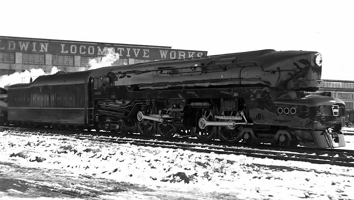
Another image of No, 5526 in front of the Baldwin works. Compared to the prototype T1s, the nose of the production engines was more blunt with less taper, and much of the side casing was omitted.
The worst wheel slip was encountered at speed when the engine would pass over some type of irregularity on the track, including moisture. The front set of drivers would slip, then catch. As soon as they caught, the rear set would slip, and then catch. This would create an imbalance and cause the front drivers to slip again, repeating the whole process. At 80 mph (129 km/h), the slip was very unsettling, and the crew had to cut power and reduce speed to stop the oscillating front-rear driver slippage. Suspension changes helped tame the T1’s wheel slip at higher speeds.
The wheel slip could also damage or break the engine’s poppet valves. Maintenance and repair of the valves and their control and drive boxes proved to be very difficult. Much of the drive system was inaccessible unless the engine was over a maintenance pit. Beyond the wheel slip, the valves began to fail in an unpredictable manner. Franklin had guaranteed the valves for continuous operation at 100 mph (161 km/h) and short bursts up to 125 mph (201 km/h). After inspecting every valve and scrutinizing numerous maintenance records, Franklin was no closer to discovering what was causing the failures. However, the majority of the valve failures occurred over a high-speed section of rail between Crestline, Ohio and Fort Wayne, Indiana. Franklin sent an observer to secretly ride the route for a month and document the train’s activity. The observer’s log detailed some remarkable findings; the T1s were often operated in excess of 130 mph (209 km/h) to make up time. One train was clocked at 142 mph (229 km/h) over several miles. Even if this one calculation was done in error, the numerous times the T1 was calculated at over 130 mph (209 km/h) could not all be mistakes. The speedometer in the cab of the locomotive stopped at 120 mph (193 km/h).

Baldwin-built No. 5533 was delivered in January 1946. As seen in this manufacturer photo, it lacks the polish applied to No. 5526 two months previous. Note that the front cylinder’s piston rod was much longer than that of the rear cylinder.
Franklin management decided the best course of action was to not inform PRR that their engineers were regularly overspeeding the trains and operating them beyond the guaranteed limits of the valves. Rather, the company decided to find a better metal that would allow the valves to endure the higher speeds and would also make the valve immune to damage from wheel slip. Franklin management felt that a more material would better serve any railroad interested in utilizing poppet valves. Although various materials were evaluated and numerous valve redesigns were considered, no solution was found. The Franklin poppet valves were simply prone to failure above 130 mph (209 km/h).
In fall 1946, T1 engine Nos. 5511 and 5539 were loaned to the Chesapeake & Ohio Railway (C&O) for trials. While C&O ultimately did not purchase any of the engines, they noted that the T1 handled well, particularly at higher speeds, and was able to make up time between stops. Most interesting, C&O did not feel that the T1 had any excessive tendency toward wheel slip.
In 1947, engine No. 6111 had its cylinders lined, which reduced the bore by 1.0 in (25 mm) to 18.75 in (476 mm). The modification was done to reduce the engine’s tractive effort and subsequently reduce wheel slippage. Seven or eight additional T1s were later modified with the cylinder liners. Also in 1947, PRR reported a net loss for the 1946 year, which was the first time in the company’s history that it did not turn a profit.
No. 5534 seen early in its career with the original front. However, the engine has a good layer of soot and dirt. Note that the tender is not marked.
In early 1948, PRR was actively converting its locomotive fleet to diesel power. In July 1948, T1 No. 5500 was fitted with Franklin Type B rotary cam valves. This change was done solely as an experiment to test the Type B unit, which was simpler and easier to maintain than the original Type A oscillating cam system. This experiment was not meant to solve the issues of valves breaking, and no other T1s were modified with the Type B unit.
In July 1949, engine No. 5547 had its Franklin Type A oscillating cam poppet valves replaced with a conventional Walschaerts valve gear. The engine was subsequently reclassified as T1a, but it was too little, too late for the T1 and PRR’s steam engines. By the end of 1949, most of the T1s had been withdrawn from service, with all of them being dropped from PRR’s roster by the end of 1953. Scrapping of the engines began in 1951, with the last T1 going under the torch in 1956. While the T1 was in standard service, engines regularly racked up over 8,000 miles (12,875 km) per month. However, steam locomotives could not match the reliability of diesel engines or their comparatively low maintenance and crew costs.
In 2013, the Pennsylvania Railroad T1 Steam Locomotive Trust (T1 Trust) was founded to build a new PRR T1 locomotive, No. 5550. Since its inception up to mid-2020, the T1 Trust has acquired or completed 34 percent of the new engine and its tender and has numerous other parts and components on order. It is the intention of the T1 Trust to complete No. 5550 by 2030 and to make the engine available for special excursion service. The T1 Trust also hopes to use No. 5550 for an attempt to break the world land speed record for a steam locomotive, which was set by the British LNER (London and North Eastern Railway) Class A4 4468 Mallard at 125.88 mph (202.58 km/h) on 3 July 1938.

An incredibly dirty engine No. 5528 sits unused in a railyard covered with soot and grime. The T1 was known to run dirty, but this engine appears to be neglected. Note the rolling stock positioned on the track immediately before the T1 and that wedges are jammed behind the engine’s rear set of drive wheels. Being cut up for scrap was the unglamorous end for all 52 T1 locomotives.
Sources:
– Loco Profile 24: Pennsylvania Duplexii by Brian Reed (June 1972)
– Pennsy Power: Steam and Electric Locomotives of the Pennsylvania Railroad, 1900-1957 by Alvin F. Staufer (1962)
– American Steam Locomotives: Design and Development, 1880–1960 by William L. Withuhn (2019)
– https://prrt1steamlocomotivetrust.org/
– http://www.steamlocomotive.com/locobase.php?country=USA&wheel=Duplex&railroad=prr
– https://revivaler.com/pennsylvania-railroad-t1-t1a-duplex/
– https://newbuildsteam.com/2017/05/13/qa-t1-5550/

Brilliant page, I enjoyed it. After the year 56 there were no more steam locomotives left in the USA?
Glad you liked it. The last T1 was scrapped in 1956. There are still steam locomotives in the US, but they are operated as attractions for people to experience steam power.
Were the same intake valves used for both the forward and backward motion of the pistons?
No, each end of each cylinder had its own set of valves. So, the intake valves on the front of the cylinder would open, allowing steam to push the piston to the rear, and intake valves at the rear of the cylinder would open, allowing steam to push the piston forward.
Many thanks for this, what a monster of a machine. Can only assume it would have easily surpassed the Mallard record, and without the benefit of a downhill stretch too!
Excellent article! Thanks very much for this work!
Loved lt great seeing all
Those great trains learned a lot
Congratulations, a definitive matter on these awesome machines.
Absolutely incredible wish they would still be about