Monthly Archives: October 2013

Moore three valve engine

General Airmotors / Moore Three Valve Aircraft Engine

By William Pearce

In the early 1900s, Robert S. Moore worked with Emile Berliner on a number of rotary engines. To manufacture the rotary engines, Berliner formed the Gyro Motor Company. Moore aided the company in one of its first projects: the conversion of an Adams-Farwell five-cylinder rotary automotive engine for aircraft use. Moore used this 50 hp engine to power an aircraft of his own design that he soloed in 1910. The Gyro engine line expanded to a variety of engines, including some with variable compression. Also, Gyro engines were used to set some aviation records. Through this work, Moore became a rotary engine expert. During World War I, he was the chief inspector of Rhone engine production. He continued to serve in the Air Corps until 1926, when he went to the Department of Commerce’s Aeronautics Branch as an engine and airplane construction expert.

Moore three valve engine

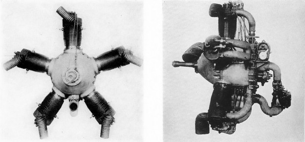
The General Airmotors / Moore three valve engine. Individual exhaust stacks are angled from the front of the cylinders. Two spark plugs can be seen in opposite sides of each cylinder. Note how the intake manifolds split to form a “Y” to supply air/fuel to each intake port.

In the late 1920s, Moore set his sights on building a new engine. He left the Aeronautics Branch and formed the General Airmotors Company, Inc out of Scranton, Pennsylvania. By 1929, he had developed, built, and tested a new radial engine with a number of new and novel features. The new General Airmotors Company engine was known as the “Three Valve Engine” and also the “Moore-Power Three Valve Engine.” Later, it became the “Scranton AP-5.” The three valve arrangement was most likely a first for a radial engine and would improve the engine’s efficiency.

Moore’s engine was an air-cooled, five-cylinder radial. Each cylinder was machined from a carbon steel forging, cast with integral cooling fins. Two spark plugs, one on each side, were positioned at the top of the cylinder and perpendicular to the cylinder axis. The top of the cylinder was enclosed except for two intake and one exhaust port. Its outer surface was machined perfect. The valve seats were in the cylinder ports, and the valve stem extended through the head. The head was made from heat treated cast aluminum and was secured to the cylinder by four bolts and a forged steel clamp. This two-piece clamp went around the circumference of the cylinder, joining a flange on the top of the cylinder with a similar flange on the bottom of the head. The large surface area contact between the cylinder and head aided the transfer of heat to the head. The clamp ensured a good seal between the cylinder and head despite the different rates of expansion as the respective components were heated by the engine’s operation.

Moore three cylinder head rocker

Not to exact scale, the image above shows the rocker arm assembly (with the exhaust rocker arm above the horseshoe intake rocker arm), a bottom view of the aluminum cylinder head (without bolt holes), and the steel cylinder. The valves would seat in the cylinder ports and their stems would pass through the head. The flange around the bottom of the head and top of the cylinder can been seen. A clamp would fit around these flanges to secure the head to the cylinder.

A unique rocker arm group sat atop each cylinder head and actuated the two 1.625 in (41.3 mm) intake valves and the single 1.875 in (47.6 mm) exhaust valve. This rocker was secured to the head by one bolt and also a support brace attached to the crankcase. The exhaust valve rocker was in the middle and extended over a horseshoe-shaped rocker that actuated both intake valves. Each rocker was actuated by a pushrod that rode on a cam ring via a roller bearing.

The two-piece crankcase was made of aluminum and split in the middle of the cylinders. The two-piece crankshaft was assembled through the one-piece master rod, to which four articulated rods were attached. Aluminum, flat-top pistons of the slipper type were used. All accessories were driven from the back of the engine. The air/fuel mixture flowed from the carburetor to an induction fan (weak supercharger) on the back of the engine. From this fan, a manifold led to each cylinder. This manifold was Y-shaped and led air to the cylinder’s two intake ports. The pushrods for the valve rockers were positioned between the “Y” of the manifold. The engine was pressure lubricated with the exception of the rockers, which were lubricated by grease.

Moore three valve section

Drawing of the top of the three valve cylinder head. The exhaust valve is on the left with the two intake valves on the right.

The five-cylinder engine had a 5.0 in (127.0 mm) bore and a 5.5 in (139.7 mm) stroke, giving a total displacement of 540 cu in (8.8 L). The engine’s compression ratio was 5.4 to 1. The engine was also fitted with a mechanism that could adjust the compression ratio to as low as 1.5 to 1. This allowed the engine to run at a variety of altitudes and with fuel of varying quality. Details on exactly how this was done have not been found. The engine was 44.5 in (1.13 m) in diameter, 41.5 in (1.05 m) long, and weighed 365 lb (166 kg). The engine was rated at 120 hp (89 kW) at 1,600 rpm and 150 hp (112 kW) at 1,850 rpm.

By June 1929, the engine was on the test stand. It was first flown in a Kreider-Reisner C-4 Challenger biplane on 9 August 1929. The engine passed a 50-hour endurance test and was awarded its Approved Type Certificate (No. 36) on 19 December 1929. There were plans to make a seven-cylinder engine that would have increased displacement by 216 cu in (3.5 L), for a total of 756 cu in (12.4 L). Engine power would have also increased to around 200 hp (149 kW). About 85% of the parts would have been interchangeable between the two engines. However, it does not appear the seven-cylinder engine was ever built.

Moore three valve section

Sectional drawing of the General Airmotors / Scranton / Moore Three Valve engine. The cam ring actuated pushrods can be seen leading to the intake and exhaust rocker arms. Also note the brace from the rocker arm assembly to the crankcase (it is angled the opposite direction from the pushrods).

With the country in the midst of the Great Depression, the General Airmotors Company fell on hard times. By early 1933, the Type Certificate was updated, with Scranton as the manufacturer, removing General Airmotors. Moore was still designing engines in 1934, but it seems he was no longer associated with the company.

Around this time, several changes were made to the engine. The bore was reduced by 0.25 in (6.3 mm) to 4.75 in (120.7 mm)—resulting in the engine’s displacement decreasing 53 cu in (0.8 L) to 487 cu in (8.0 L). The engine’s compression ratio was dropped to 5.2 to 1, but its operating rpm was increased. The three valve engine was now rated at 155 hp (116 kW) at 1,900 rpm and 165 hp (123 kW) at 2,000 rpm. The cylinder head cooling fins were enlarged to dissipate the extra heat generated by the increased engine speed and power. The updated engine weighed 20 lb (9 kg) more at 385 lb (175 kg). Despite the improvement efforts, the three valve engine’s fortune never turned around; the engine’s Type Certificate was allowed to expire in 1937.

Scanton three valve engine

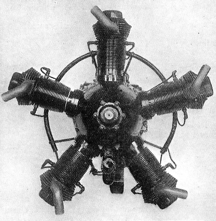
The Scanton three valve engine with a decreased bore but increased rpm. Note the larger cylinder head cooling fins as compared to the earlier three valve engine.

Sources:
The Moore-Power Three Valve Engine by General Airmotors Company, Inc. (circa 1930)
Directory of American Aircraft Engines 1931 Edition by The International Nickel Company
Directory of Aircraft Engines 1935 Edition by The International Nickel Company
Aerosphere 1939 by Glenn Angle
Jane’s All the World’s Aircraft 1932 by C.G. Grey
– “Gas Engine” US patent 1,820,475 by Robert S. Moore (granted 25 August 1931)
“Internal Combustion Engine” US patent 1,915,237 by Robert S. Moore (granted 20 June 1933)
– “Valve Mechanism for Internal Combustion Engines” US patent 1,965,466 by Robert S. Moore (granted 3 July 1934)
http://earlyaviators.com/emoore.htm (and links contained therein)

Alcor Duo-6 Lockheed

Alcor Duo-4, Duo-6, and C-6-1 Transports

By William Pearce

In 1929, the Lockheed Aircraft Corporation was bought by the Detroit Aircraft Corporation. Lockheed’s founder, Allan H. Loughead (phonetically pronounced Lockheed) was unhappy with the acquisition and had voted against it. Allan left and formed a new company in 1930 with his brother Malcolm. The pair had worked together in aviation before pursuing separate interests in the 1920s. The new company was known as the Lockheed Brothers Aircraft Corporation.

Alcor Duo-4 front

The Duo-4 with “Olympic” written on the nose. Note the cooling slits for the Menasco Pirate engines.

Their first aircraft was the Olympic Duo-4, and its fuselage was similar to the Lockheed Vega 5. In place of the Vega’s single radial engine were two Menasco C4 Pirate engines. These in-line, four-cylinder engines were air-cooled and produced 125 hp (92 kW). The engines were positioned in the nose of the Duo-4 so that the tips of the propellers cleared each other by about 3 in (76 mm). The engines were laid on their sides so that their heads were close together and the crankshafts were farthest apart and canted out at a slight angle. The Duo-4’s engine arrangement had less air resistance than a normal twin-engine plane. In addition, when one engine was shut down, the Duo-4 behaved much like a single-engine aircraft.

The four to six passenger Duo-4 was a high-wing cantilever monoplane. The monocoque fuselage had a wooden structure and was covered with a plywood skin that was molded under pressure. The wings also had a wooden structure and were covered with plywood. The aircraft (registered as NX962Y) was first flown by Frank Clarke in 1930. In March 1931, the Duo-4 was damaged when a sudden gust of wind caused it to nose-over and then collide with a vehicle during a landing at Muroc (now Edwards Air Force Base), California. Unfortunately, this incident caused investors to back away from the Lockheed Brothers Aircraft Corporation, and funds were not available to quickly repair the Duo-4.

Alcor Duo-4 Pancho Barnes

The Olympic Duo-4 at Muroc Dry Lake with Florence “Pancho” Barnes. Note that “Olympic” no longer appears on the nose and the propeller tip clearance.

Over the next few years, the Duo-4 was slowly repaired and modified. The four-cylinder Pirate engines were replaced by six-cylinder Menasco B6S Buccaneer engines. The supercharged, 230 hp (171 kW) Buccaneers were in-line, air-cooled engines and turned 7 ft 6 in metal propellers. After the modifications, the aircraft was renamed the Duo-6 (some sources refer to it as the Loughead Alcor). It flew again in early 1934.

Allan Loughead officially changed his name to Allan Lockheed in February 1934. Also in 1934, the Lockheed Brothers Aircraft Corporation went out of business, but Allan continued with the Duo-6. In May 1934, one propeller was removed to demonstrate the Duo-6’s single engine performance. At Mines Field (now Los Angeles International Airport), the Duo-6 took off in 1,200 ft (366 m) and attained 130 mph (209 km/h) on just one engine. Reportedly, with one engine shut down, the aircraft handled with little yaw, much like a single-engine plane. In May, Allan flew the Duo-6 back east to demonstrate it to the Navy and Army. However, nothing came from this exposure.

Alcor Duo-6 Lockheed

The Duo-6 on its trip back east with Allan Lockheed in front. Note that “Alcor” is written on the tail and the changes to the engine cowling from the Duo-4 image above.

In October 1934, the United States placed operating restrictions on single-engine transports carrying passengers. This regulation marked a permanent shift to multi-engine transports for passenger service. Presumably, the twin-engine Duo would have done well under the new regulations with its ability to perform like a conventional single-engine aircraft in the event of one engine being shut down. Unfortunately, the Duo-6 crashed in late 1935 and was not repaired.

The Duo-4 and Duo-6 had a 42 ft (12.80 m) wingspan and were 28 ft 6 in (8.69 m) in length. The Duo-4 had an empty weight of 2,265 lb (1,027 kg). The aircraft had a max speed of 140 mph (225 km/h) and a landing speed of 47 mph (76 km/h). The Duo-6 had an empty weight of 2,885 lb (1,309 kg) and a gross weight of 5,090 lb (2,309 kg). The aircraft had a max speed of 183 mph (295 km/h), a cruise speed of 157 mph (253 km/h), and a landing speed of 57 mph (92 km/h). The service ceiling was 18,500 ft (5,639 m) and its range was 660 mi (1,062 km). The single engine performance of the Duo-6 was a max speed of 125 mph (201 km/h), a cruise speed of 100 mph (161 km/h), and a ceiling of 6,400 ft (1,951 m).

Alcor C-6-1 top

This unique top view of the C-6-1 doing an engine run shows how the engine nacelles were blended into the nose and wings.

In February 1937, Allan started a new aviation company: the Alcor Aircraft Corporation. The “Alcor” came from Allan Lockheed Corporation. Alcor’s first official aircraft (the Duo-6 had been built before the company was formed) was the C-6-1 Junior Transport. It was designed to carry six to eight passengers. The C-6-1 used the engine installation of the Duo but with improved C6S-4 Super Buccaneer engines that produced 275 hp (205 kW) at 2,400 rpm for takeoff. Each engine was canted out 4 degrees and the propellers cleared each other by 12 in (0.3 m).

The aircraft had a low-wing, and the main gear retracted back into the wing with the wheels turning 90 degrees to lay flat. The wings and fuselage had a structure made mostly of wood. However, there were some components in high-stress areas that were made of metal. The fuselage had a circular section and was made up of laminated spruce framework with a two-piece plywood skin that was molded under pressure. The engines were closely cowled and faired into the nose and wing. The C-6-1 was a streamlined aircraft that was very efficient and had excellent flight characteristics.

Alcor C-6-1 side

Side view of the Alcor C-6-1 Junior Transport complete with spinners.

The Junior Transport had a wingspan of 49 ft (14.94 m) and a length of 31 ft 8 in (9.65 m). The aircraft had an empty weight of 4,141 lb (1,878 kg) and a gross weight of 6,200 lb (2,812 kg). The aircraft had a max speed of 211 mph (340 km/h) at 5,500 ft (1,676 m) and a cruise speed of 190 mph (306 km/h) at 5,500 ft (1,676 m) and 200 mph (322 km/h) at 10,000 ft (3,048 m). The service ceiling was 24,000 ft (7,315 m) and its range was 835 mi (1,344 km). On one engine, the C-6-1 had a top speed of 147 mph (237 km/h), could cruise at 129 mph (208 km/h), and had a ceiling of 12,600 ft (3,840 m).

The C-6-1 (registered as NX15544) was first flown on 6 March 1938. On a test flight over San Francisco Bay on 27 June 1938, the C-6-1 went out of control during a high-speed dive. The dive test was instigated by the pilot and not part of the flight schedule. Unable to regain control, the pilot and observer bailed out, leaving the sleek C-6-1 to crash into the bay. The aircraft was insured, but the funds were only sufficient to pay off Alcor’s debts. With no capitol, Allan closed out Alcor. Allan continued to be involved in aviation for the rest of his life, but he did not build any further aircraft of his own design.

Even though the Duo-4 and Duo-6 were built under Lockheed Brothers Aircraft Corporation name, they are often referred to as the Alcor Duo-4 and Alcor Duo-6. In addition, the Alcor C-6-1 is often incorrectly referred to as the Lockheed Alcor.

Alcor C-6-1 flight

Alcor C-6-1 on a fight over San Francisco Bay. The San Francisco Bay Toll-Bridge (now San Mateo–Hayward Bridge) can be seen in the background. Note the absence of spinners on the otherwise sleek aircraft.

Sources:
Jane’s All the World’s Aircraft 1932 by C.G. Grey
Jane’s All the World’s Aircraft 1934 by C.G. Grey
Jane’s All the World’s Aircraft 1938 by C.G. Grey and Leonard Bridgman
Lockheed Aircraft since 1913 by Rene J. Francillon (1982/1987)
– “Commercial Aviation: An American Feeder-Line Machine,” Flight 6 July 1934
– “A ‘Flat’ Engined Transport,” Flight 12 May 1938
http://1000aircraftphotos.com/Contributions/HornDavid/9336.htm
http://www.aerofiles.com/_al.html
Brief Allan Lockheed 1910-1942 Autobiography
http://en.wikipedia.org/wiki/Allan_Loughead