Category Archives: Between the Wars

Westland-F7-30-front-left

Westland F.7/30 (PV.4) Biplane Fighter

By William Pearce

On 1 October 1931, the British Air Ministry issued Specification F.7/30 for a single-seat day and night fighter. Further requirements of Specification F.7/30 were for the aircraft to be capable of at least 195 mph (314 km/h) at 15,000 ft (4,572 m), have a landing speed of 50 mph (80 km/h), carry an armament of four machine guns, and offer the pilot an unobstructed, all-around field of view. Aircraft developed from Specification F.7/30 were expected to outperform then-current contemporary fighters in respect to handling, maneuverability, range, rate of climb, and service ceiling.

Westland-F7-30-in-flight

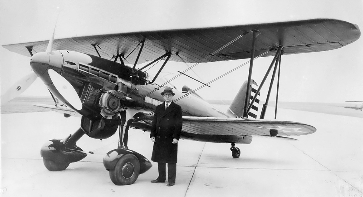
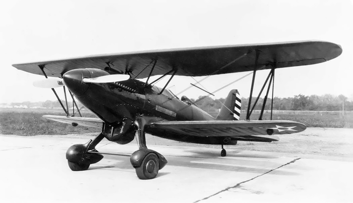
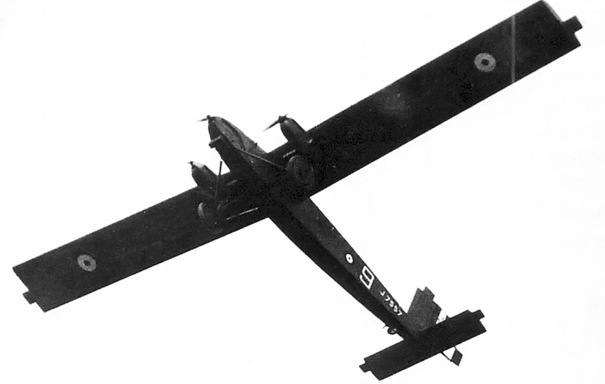
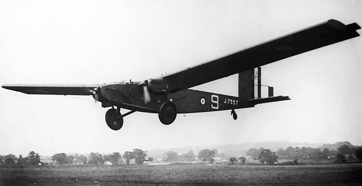
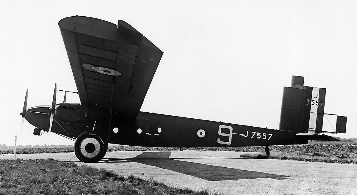
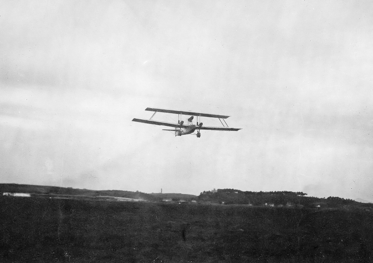
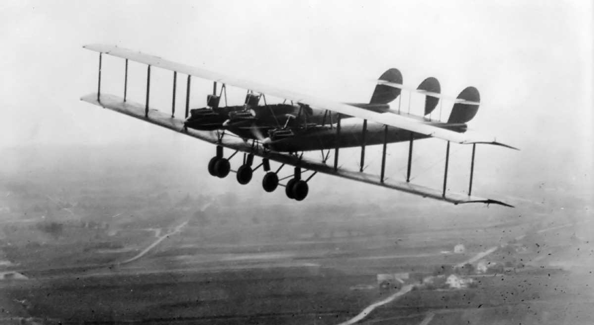
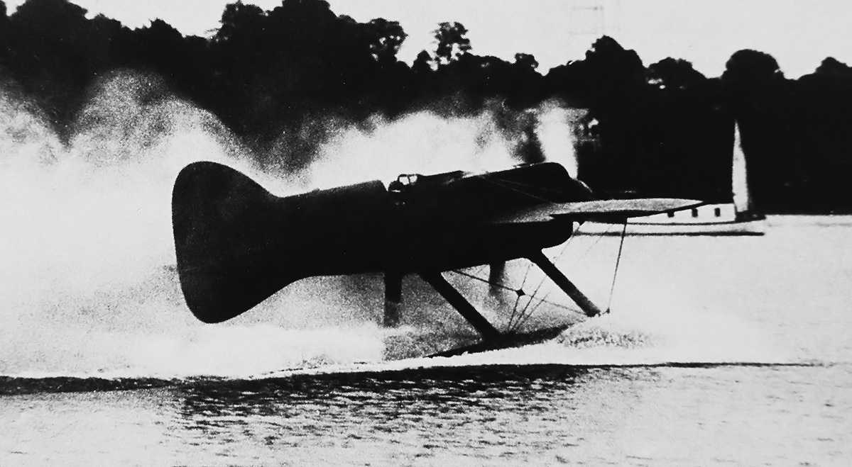
The Westland F.7/30 (PV.4) on an early test flight. The aircraft is seen with its original open canopy and exhaust manifolds. Note the good visibility from the pilot’s position.

Numerous manufacturers responded to Specification F.7/30, including Blackburn with the F.3 biplane, Bristol with the Type 123 biplane and Type 133 monoplane, Gloster with the SS.37 biplane, Hawker with the P.V.3 biplane, Supermarine with the Type 224 monoplane, and Westland with the F.7/30 biplane. In addition to the F.7/30 biplane, Westland also submitted a high-wing monoplane design. However, the monoplane’s long wingspan and comparatively high landing speed resulted in the biplane being selected by the Air Ministry.

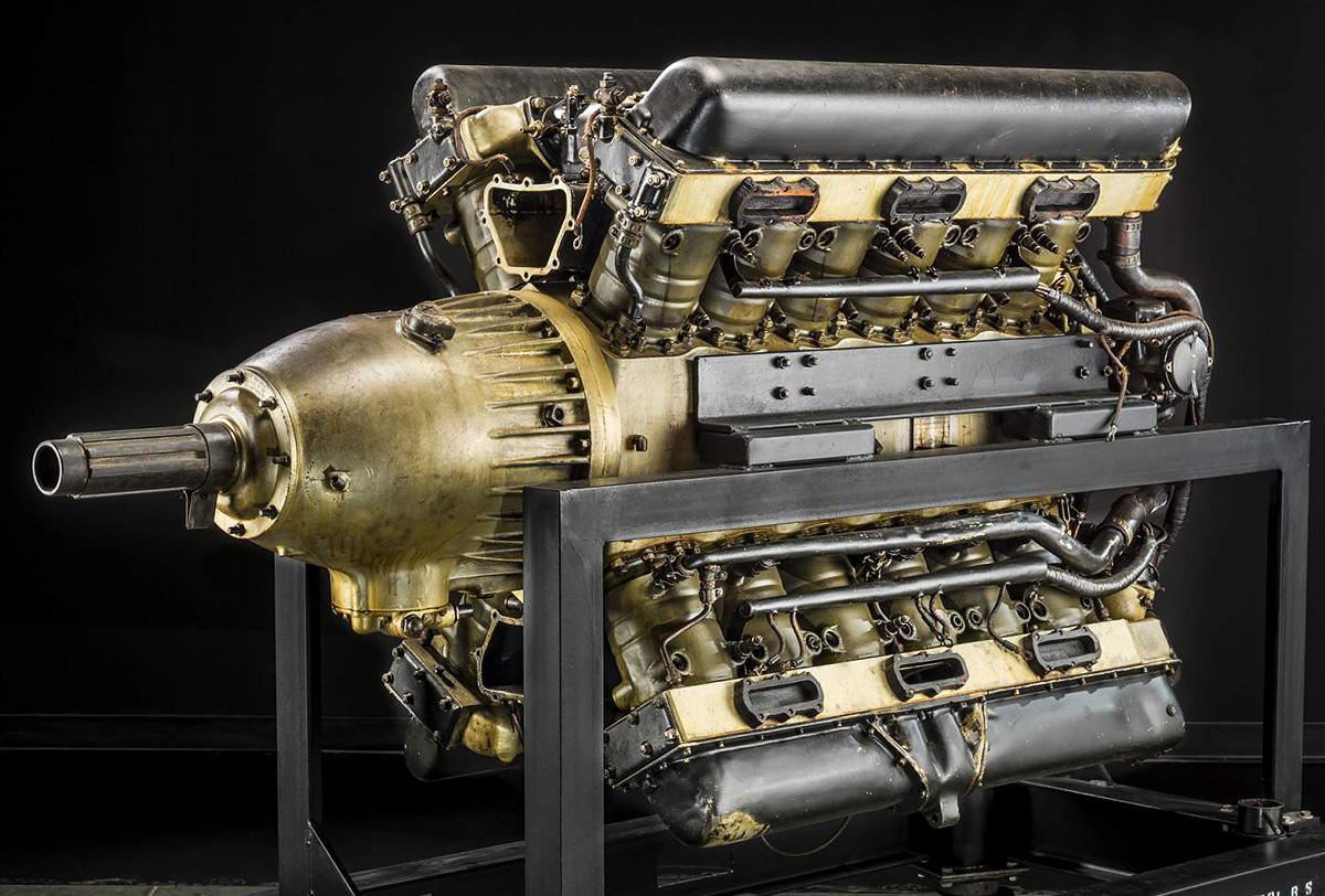
Although an engine type was not listed in Specification F.7/30, the Air Ministry informally expressed a strong preference for the Rolls-Royce Goshawk. The Goshawk was a development of the Rolls-Royce Kestrel IV V-12, which was the most advanced British liquid-cooled production engine at the time. While both the Kestrel and the Goshawk had a 5.0 in (127 mm) bore, a 5.5 in (140 mm) stroke, and displaced 1,296 cu in (21 L), the Goshawk employed evaporative (steam) cooling.

Westland-F7-30-front-left

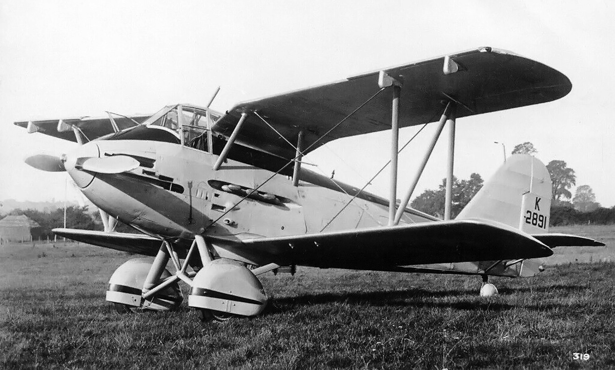
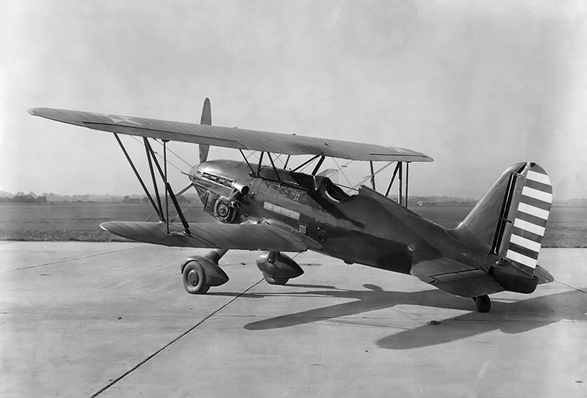
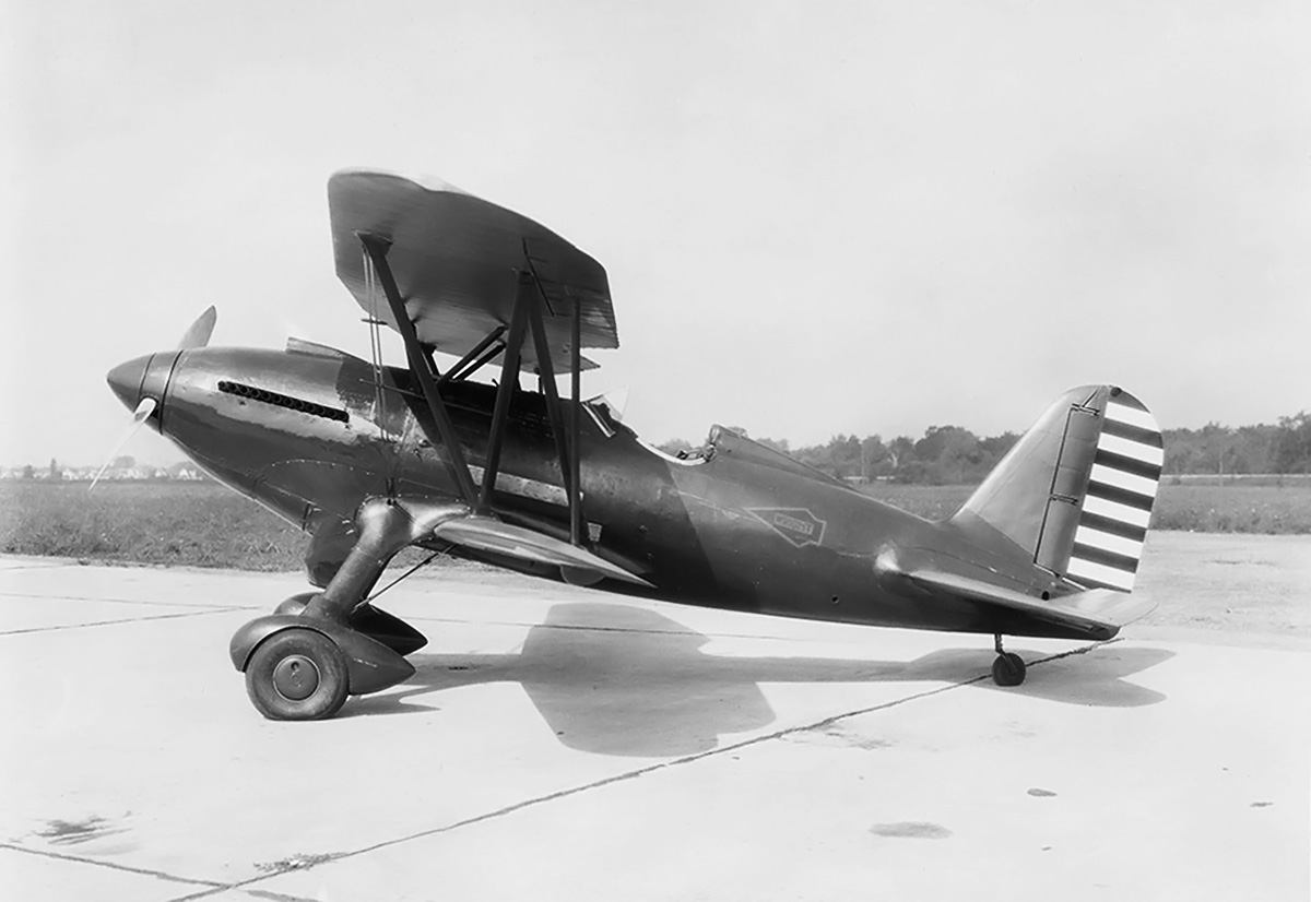
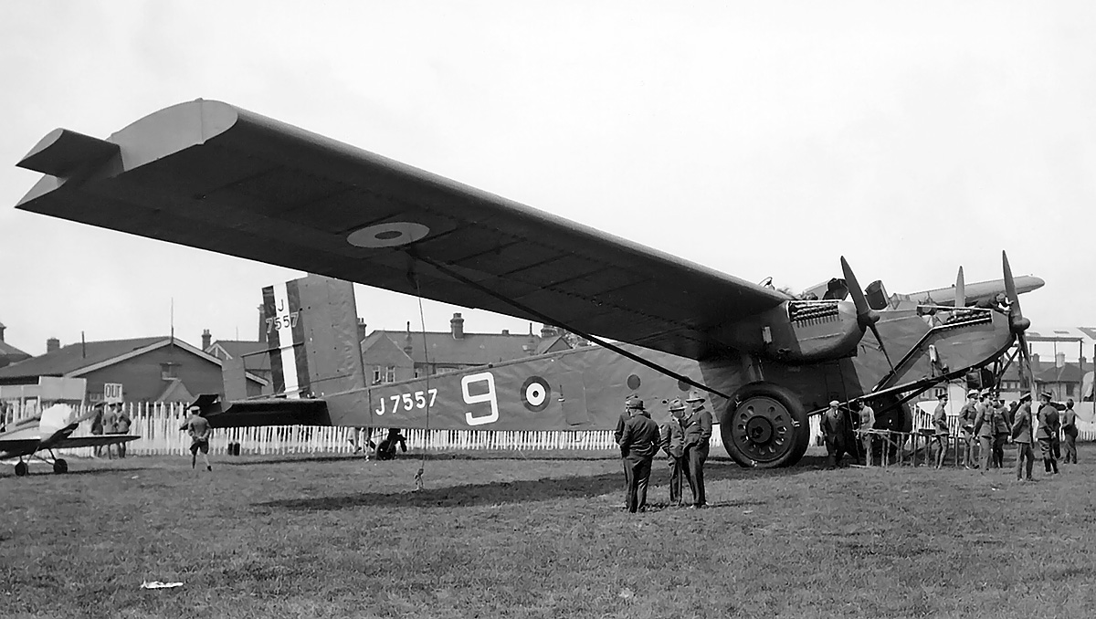
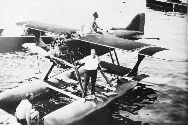
The Westland F.7/30 with an enclosed canopy but still with the original exhaust manifolds. The leading-edge slats are visible on the upper wing.

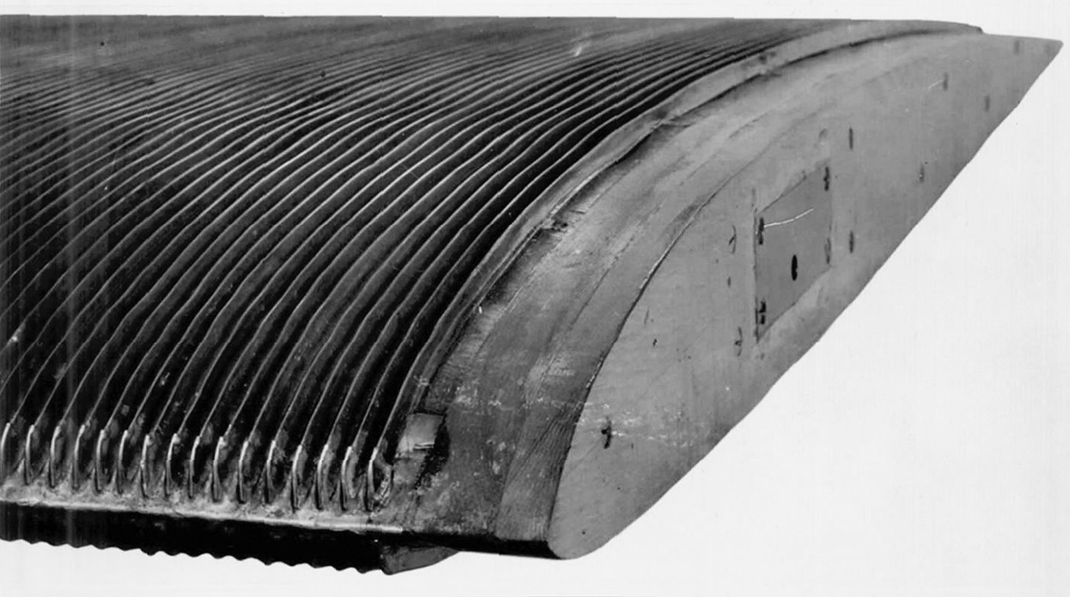
The basic premise behind evaporative cooling for aircraft engines was that cooling water would enter the engine and be allowed to boil as it flowed through the hottest part of the engine, the cylinder heads. The conversion of water to steam allowed for more heat to be taken from the engine compared to traditional water cooling. The steam would then be fed though a condenser (heat exchanger), in which the steam would cool and convert back to water. The condenser could be incorporated into the aircraft’s structure, such as the wing’s leading edge and skin, and the condenser would be cooled by the slipstream of air flowing over its surface. In theory, the end result of evaporative cooling compared to conventional water cooling was a more efficient system that eliminated the drag of a conventional radiator. In practice (with various installations), evaporative cooling systems were complex, leaked steam, had inefficient or ineffective condensers, and could suffer from vapor lock.

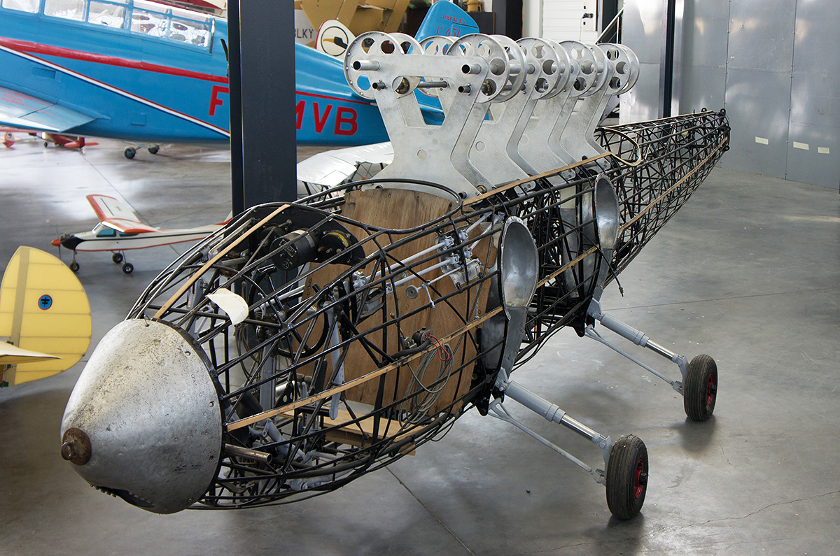
The Westland F.7/30 originally carried the company designation PV.4, and it was designed by Arthur Davenport, Westland’s chief designer, with input from Harald Penrose, Westland’s chief test pilot. Most of the aircraft designed for Specification F.7/30 were fairly conventional. However, the Westland F.7/30 incorporated some unconventional features. A biplane arrangement was selected to satisfy the 50-mph (80-km/h) landing speed and maneuverability requirements of Specification F.7/30. The cockpit was placed in the extreme nose of the aircraft and forward of the upper wing to provide an unobstructed view for the pilot. This necessitated moving the engine from the nose of the aircraft to behind the cockpit, with an extension shaft driving the propeller.

The aircraft’s center and forward fuselage had a tubular aluminum frame and were covered by removable aluminum panels. The rear fuselage and tail had an aluminum frame and were cover by fabric. The upper and lower wings attached to the center fuselage, which was strengthened to support the engine. The upper wing was of the gull-type to improve the pilot visibility and was equipped with ailerons and automatic leading-edge slats. A 49 US gal (41 Imp gal / 186 L) fuel tank was located in the inboard section of each upper wing. The lower wing was staggered behind the upper wing, had a reduced span, and was straight with no control surfaces. Both upper and lower wings had aluminum frames with aluminum skin covering the leading edge and fabric covering the rest of the wing. All control surfaces had fabric-covered aluminum frames.

Westland-F7-30-side

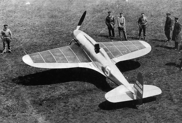
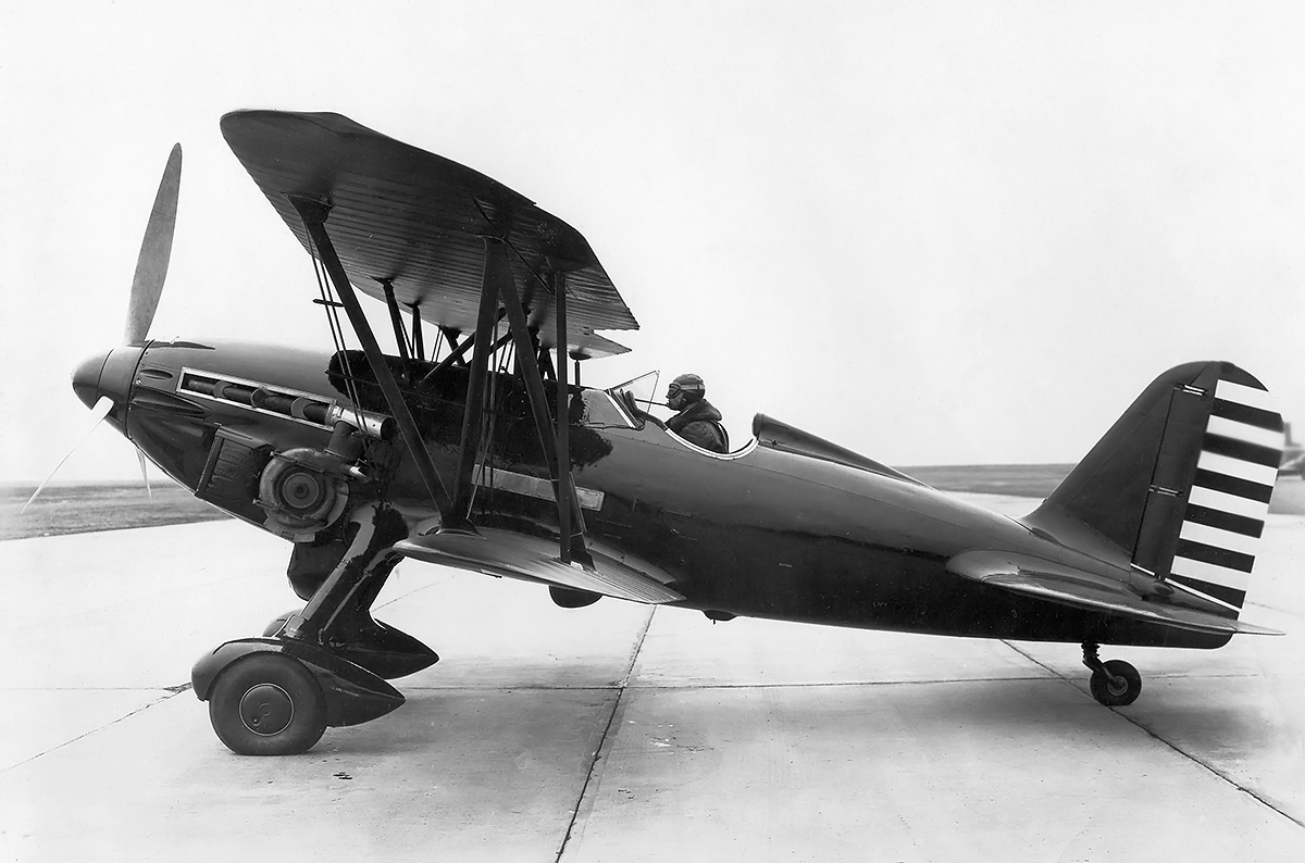
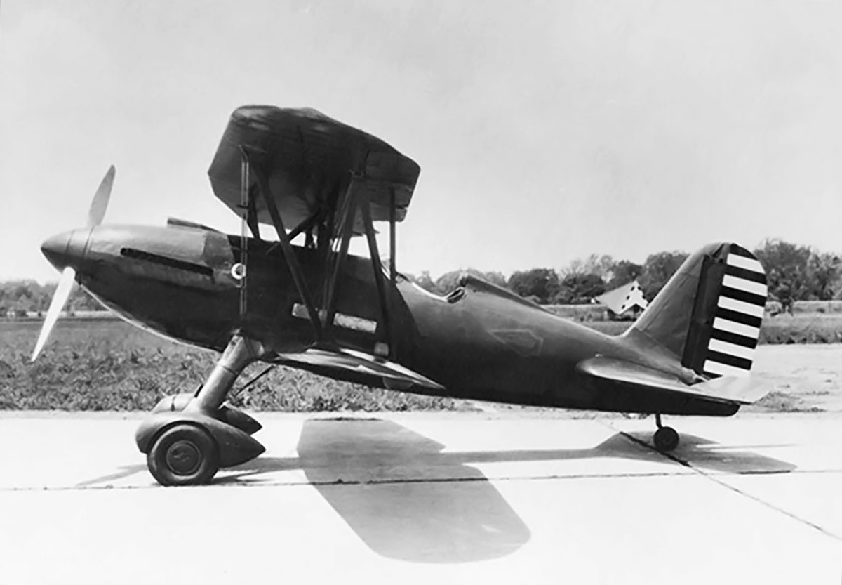
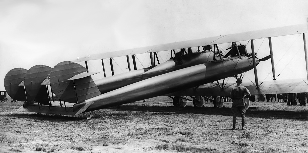
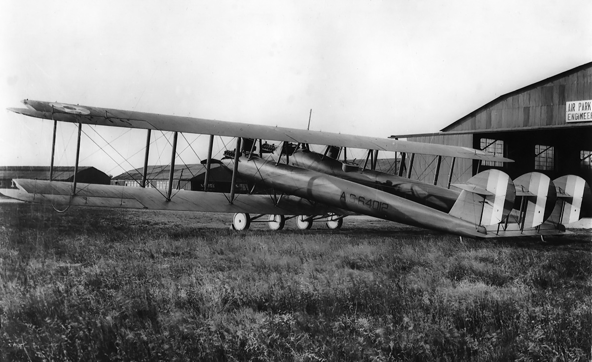
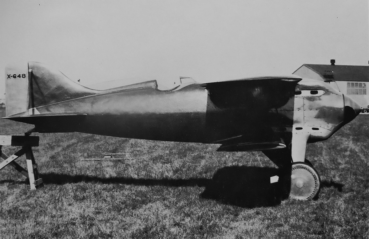
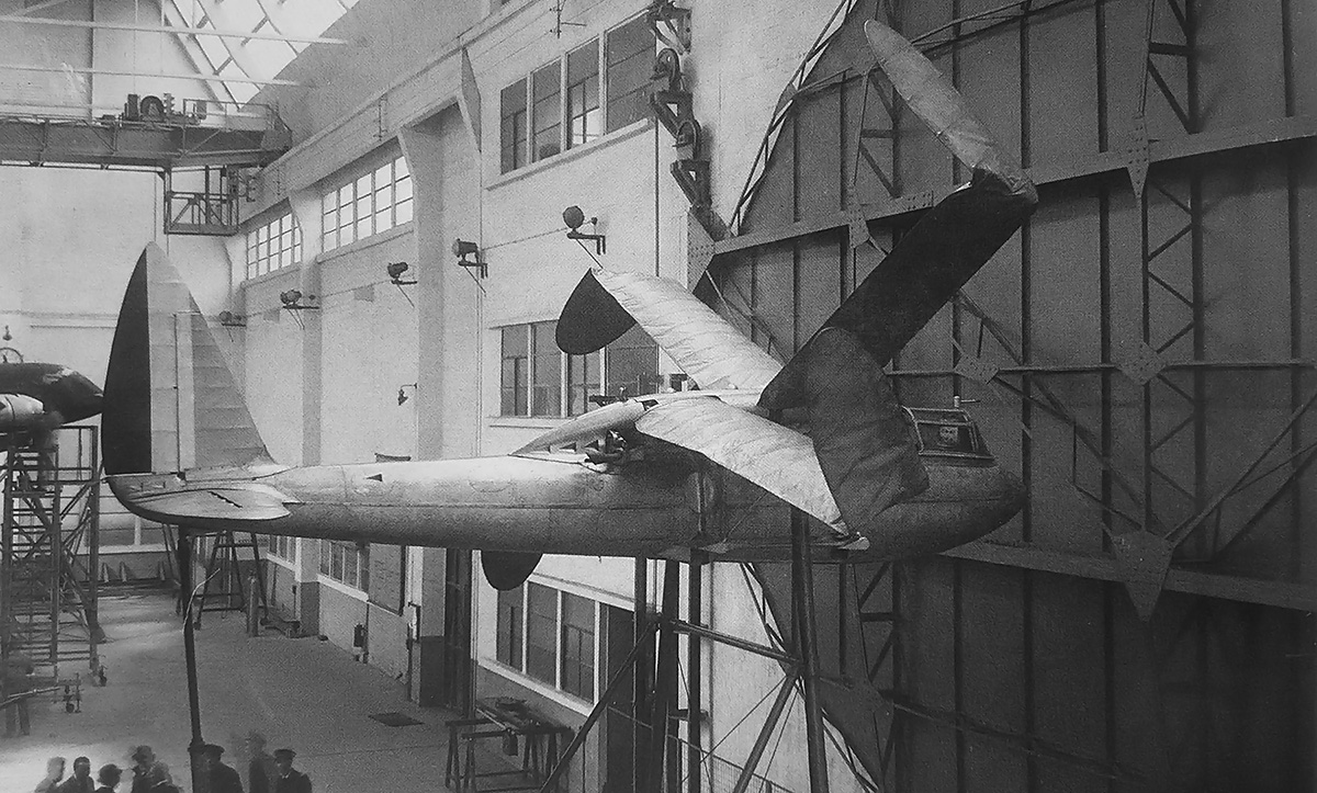
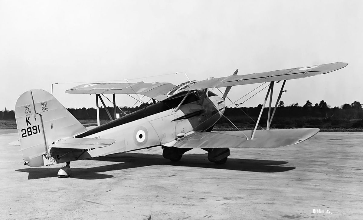
Side view of the Westland F.7/30 with the updated exhaust manifolds. Note the barrel of the upper machine gun extending almost to the propeller, while the lower machine gun was almost completely recessed. The odd structure forward of the canopy is the gun sight.

The Goshawk II engine produced 600 hp (447 kW) at 2,600 rpm and was installed in the center of the aircraft. An extension shaft ran from the engine, under the cockpit, and to a propeller reduction gear in the nose of the aircraft where it turned a 10 ft 4 in (3.15 m) diameter, two-blade, wooden propeller. The condenser (radiator) was mounted under the lower wing’s center section. The engine’s exhaust manifolds protruded from each side of the fuselage between the upper and lower wings. Two machine guns were mounted on each side of the aircraft. The lower machine guns were mounted below the exhaust manifolds, and the upper machine guns were mounted by the cockpit in the forward fuselage. All four Vickers .303 machine guns, each with 140 rounds, were synchronized to fire through the propeller. The cockpit was originally open but was later fitted with an enclosed canopy. The main landing gear was mounted just forward of the lower wing. The main gear and tailwheel were covered with aerodynamic fairings.

The Westland F.7/30 had a wingspan of 38 ft 6 in (11.7 m), a length of 29 ft 6 in (9.0 m), and a height of 10 ft 9 in (3.3 m). The aircraft had an estimated top speed of 185 mph (298 km/h) at 15,000 ft (4,572 m) and a landing speed of 55 mph (89 km/h). Time to climb to 20,000 ft (6,096 m) was 18 minutes. The Westland F.7/30 had an empty weight of 3,624 lb (1,644 kg) and a loaded weight of 5,170 lb (2,345 kg).

In July 1932, Westland received an order from the Air Ministry to build a F.7/30 prototype, and the aircraft was given serial number K2891. Construction of the prototype was undertaken at the Westland factory in Yeovil in southern England. Behind schedule, the aircraft was completed in early March 1934. Ground handling tests were undertaken in mid-March. After some adjustments, the aircraft was transported by ground to Royal Air Force Station Andover for its initial flight. The first flight was made on 23 March 1934 with Harald Penrose at the controls. The aircraft handled well, and Penrose soon flew it back to Yeovil.

Westland-F7-30-front

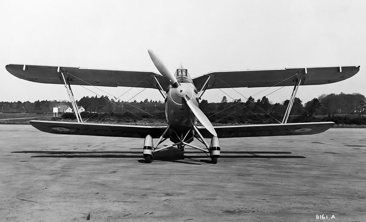
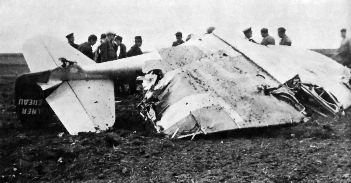
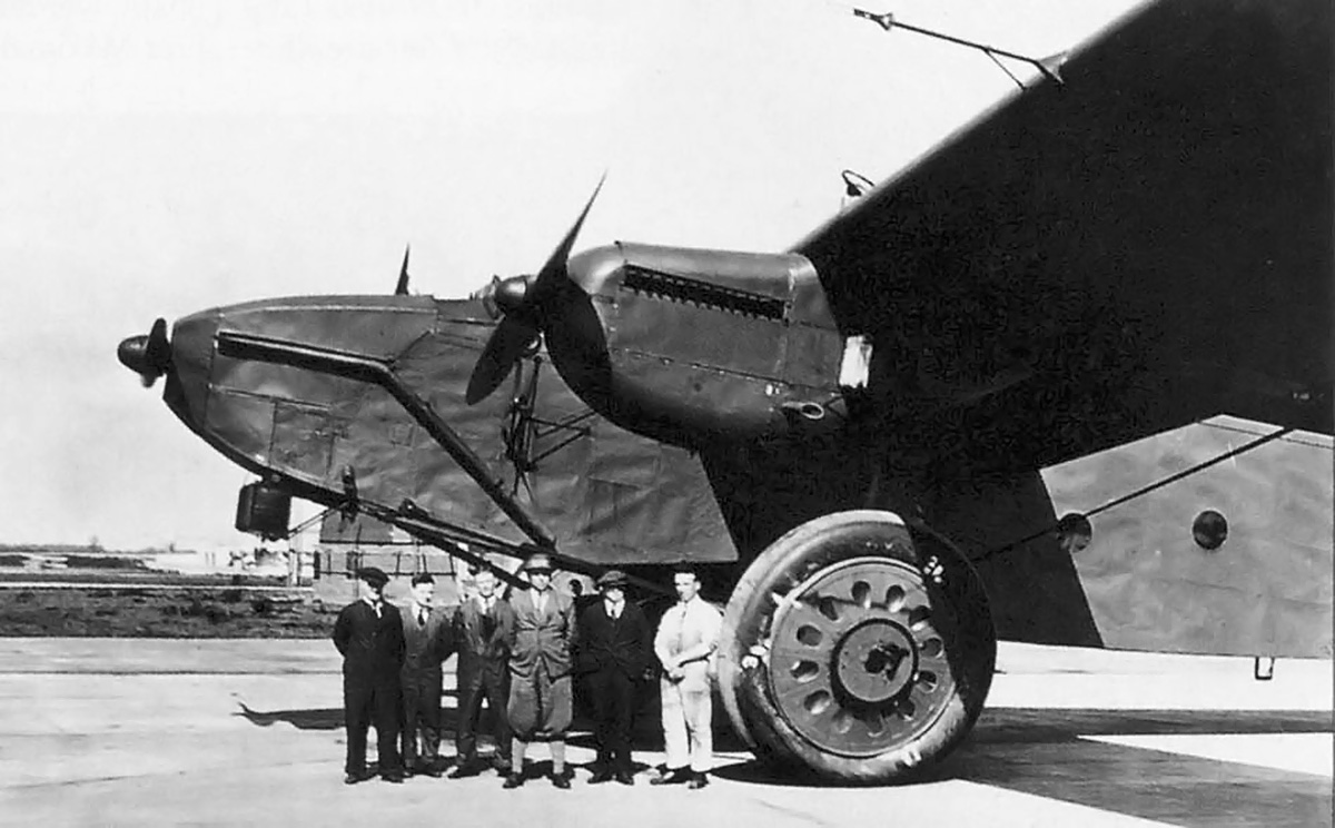
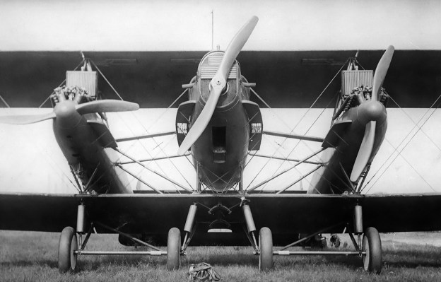
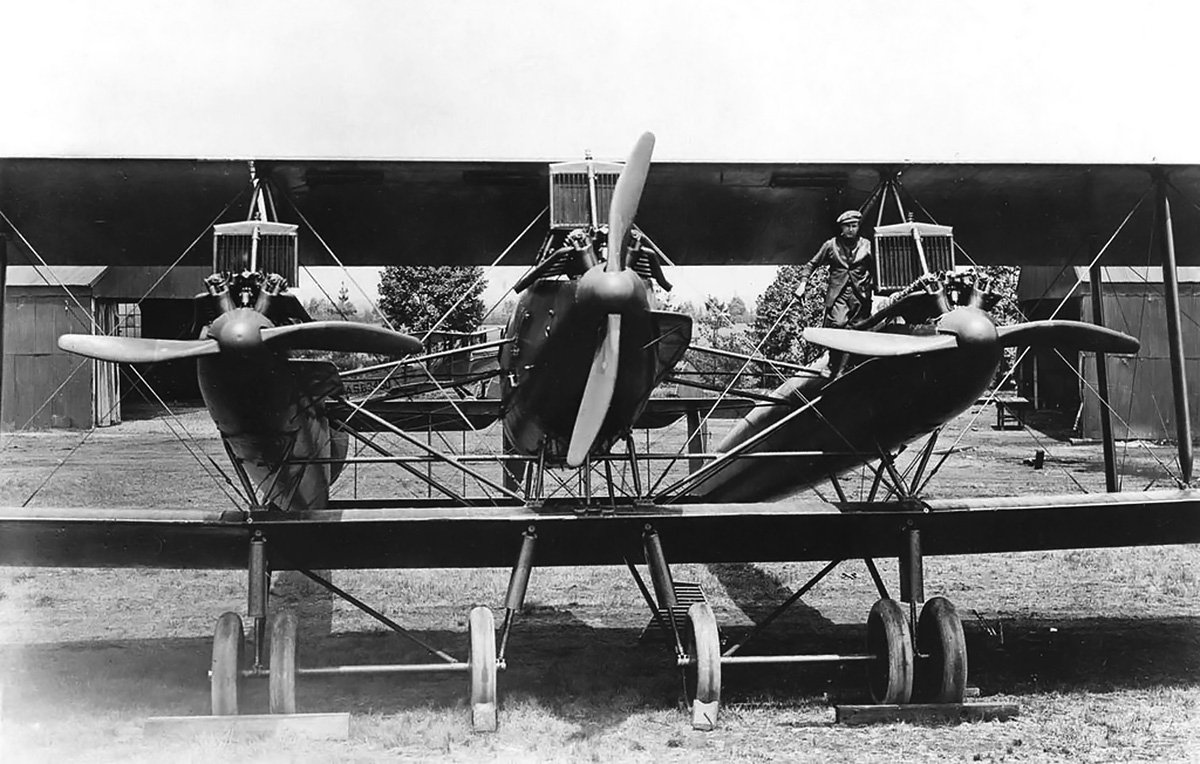
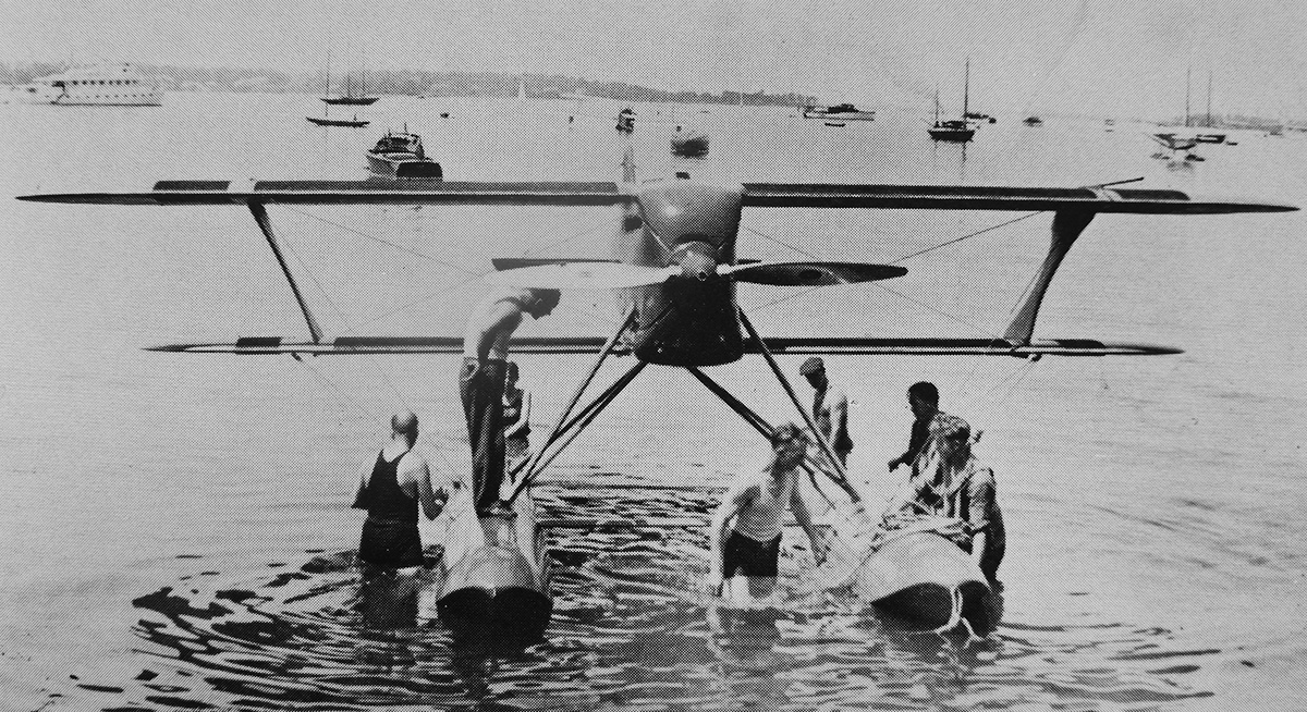
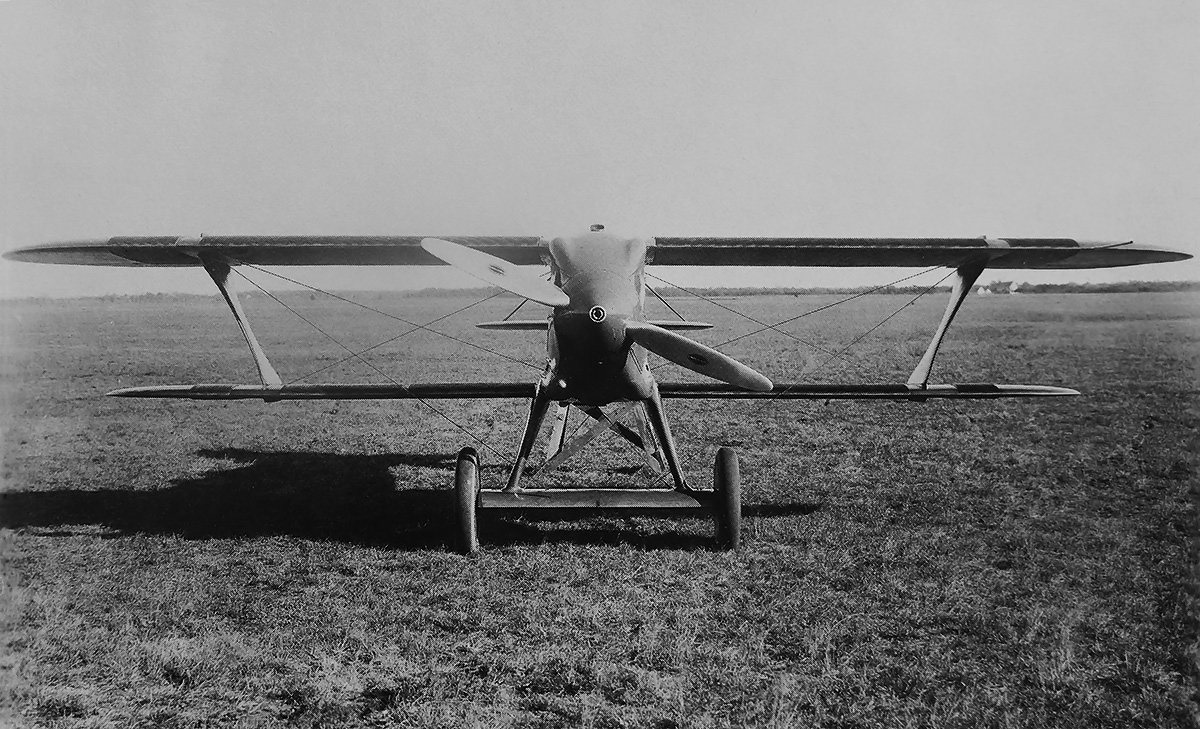
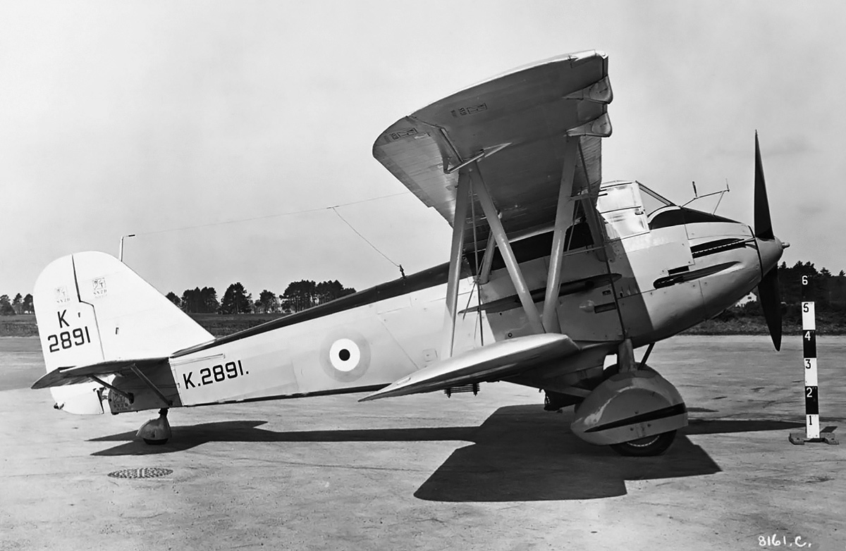
Front view of the Westland F.7/30 illustrates the condenser (radiator) under the lower wing. The landing gear supports did nothing to improve airflow into the condenser, and the additional struts for the gull wing did nothing to improve the aircraft’s aerodynamics.

Continued flight testing revealed that the pilot experienced an uncomfortable amount of buffeting in the open cockpit at cruising speed or higher. Also, the cooling system was barely adequate, with engine temperature always running near its upper limit. Flight testing continued, and the Westland F.7/30 was found to have a top speed of only around 145 mph (233 km/h).

The cockpit was enclosed to improve pilot comfort and also in an effort to increase the aircraft’s speed. More flight testing occurred, and it was discovered that as the aircraft rolled to 90 degrees, the engine’s hot exhaust would burn the fabric covering the rear fuselage. The exhaust manifolds were subsequently modified to resolve this issue. The new manifolds had a single exit that was positioned toward the front of the engine, allowing the hot exhaust to flow back against the non-flammable metal manifold so that it was sufficiently cooled by the time it reached the rear fuselage’s fabric covering.

The Westland F.7/30 was evaluated by the Aeroplane and Armament Experimental Establishment at Martlesham Heath Airfield in mid-1934. Maximum speeds of only 146 mph (235 km/h) at 10,000 ft (3,048 m) and 122 mph (196 km/h) at 20,000 ft (6,096 m) were recorded. Development of the Westland F.7/30 was abandoned in 1935, as its performance was far below expectations and that of the other F.7/30 competitors. For all of the aircraft powered by Goshawk engines, the complex evaporative cooling system was prone to overheating and found to be unsuitable for service aircraft. The Westland F.7/30 was ultimately scrapped. The winner of Specification F.7/30 was the Gloster SS.37, which was powered by a conventional radial engine. Put into production as the Gloster Gladiator, it was Britain’s last biplane fighter and an aircraft that served nobly in World War II.

Westland-F7-30-rear

Although the Westland F.7/30 flew well, its performance was far below contemporary fighter aircraft. The winner of Specification F.7/30, the Gloster Gladiator, was 100 mph (161 km/h) faster.

Sources:
Westland Aircraft since 1915 by Derek N. James (1991)
Interceptor Fighters by Michael J. F. Bower (1984)
British Piston Aero-Engines and Their Aircraft by Alec Lumsden (2003)
British Flight Testing by Tim Mason (1993)
https://www.alternatehistory.com/forum/threads/specification-f-7-30.368722/
https://www.secretprojects.co.uk/threads/british-f-7-30-fighter-specification.29612/

Kellner-Bechereau-28VD-top

Kellner-Béchereau 28VD Air Racer

By William Pearce

Société Kellner was a French luxury coachbuilder run by Georges Kellner. During World War I, the company turned to producing SPAD VII, S.XI, and S.XIII fighter aircraft under license. The SPAD (Société Pour L’Aviation et ses Dérivés / Company for Aviation and its Derivatives) aircraft were designed by French aeronautical engineer Louis Béchereau. After World War I, Société Kellner returned to coach making, and SPAD went out of business. Béchereau progressed through a number of companies until 1926, when he founded the Société pour la Réalisation d’Avions Prototypes (SRAP / Prototype Aircraft Company).

Kellner-Bechereau-28VD-construction

The Kellner-Béchereau 28VD under construction. The cowling attached to the very front of the aircraft contained the surface oil cooler. The top of the coolant tank is visible just behind the fairing atop the engine. Note the fuel tanks forward and aft of the cockpit.

Société Kellner was taken over by Jacques Kellner after his father’s passing. Jacques was an aviation enthusiast and wanted to steer the company back to being involved with aviation. In 1931, Jacques Kellner joined forces with Louis Béchereau to form Avions Kellner-Béchereau in Boulogne-Billancourt, France. Kellner-Béchereau immediately began designing aircraft, and one of their first concepts was that of the 28VD (also known as KB-28), an air racer intended for the 1933 Coupe Deutsch de la Meurthe. The Coupe Deutsch de la Meurthe was a race to cover 1,242 miles (2,000 km) with a mandatory 90-minute stop at 621 miles (1,000 km), and aircraft were limited to using a single engine with a displacement no greater than 488 cu in (8.0 L). Additional stops could be made but were not mandatory and would count against the total time to finish the course. Ten laps of the 124-mile (200-km) course would complete the race, and the rhombus-shaped course was laid out with towns of Chartres, Moisy, Orléans, and Étampes at its corners. The Étampes-Mondésir airfield was the start and finish point, and the prize in 1933 was four million Francs.

The Kellner-Béchereau 28VD was a low-wing taildragger made almost entirely of metal, and its design was tested in a wind tunnel. The aircraft’s slim monocoque fuselage was of all-aluminum construction with an open cockpit at its center. A sloped fairing led up to the cockpit, and an extended headrest trailed from it. This resulted in the pilot sitting rather low with little forward visibility, but side visibility was quite good. Fuel tanks were housed in front of and behind the cockpit. The aircraft’s vertical and horizontal stabilizers were made of aluminum, but the rudder and elevators were made of wood. The angle of the horizontal stabilizers was adjustable and could be altered to trim the aircraft while in flight. An aerodynamic fairing partially covered the tailskid.

Kellner-Bechereau-28VD-maintenance

The 28VD undergoing final touches. This image gives a good view of how the surface radiators wrapped around the wing’s leading edge. Note the large Ratier metal propeller. Intakes to the engine’s superchargers can just been seen on the cowling’s undersides.

The relatively-short, cantilever wings of the 28VD were attached to the fuselage by a main spar at its center and a rear spar. The wings were further supported by false front and rear spars. A large aileron ran almost the entire length of the wing’s trailing edge and was attached to the false rear spar. Wing construction kept its interior mostly open, and three fuel tanks were positioned in each wing. Each of the wing tanks was equipped with a quick-drain dump valve 3.94 in (10 cm) in diameter. For the valve, carbonic acid gas was fed into a space that blew out a lower seal, allowing an upper plug to fall free followed by the contents of the fuel tank. Although not specifically stated, it is presumed that the pilot would control the flow of the carbonic acid gas to initiate the fuel dump. It is not clear if the fuselage tanks were also equipped with a dump valve.

The upper surface of each wing was covered with radiators in five sections. Each surface radiator section consisted of a forward and rear part. The front radiator for each section curved around the front of the wing to form the leading edge. The inner three radiator sections terminated shortly after making the turn to the wing’s underside. The outer two sections continued around the leading edge to cover the front half of the underwing, and additional radiators covered the rear outer surface under the wing. Water from the coolant tank installed above the engine flowed through pipes in the wing’s leading and trailing edges and then into the surface radiators. After passing through the radiator, the cooled water was collected in a tube running along the center spar and returned to the engine. A large fairing connecting the wing’s trailing edge to the fuselage contained a number of louvers to allow heat, vapors, and moisture to escape from the wing.

Kellner-Bechereau-28VD-right

The newly completed 28VD is rolled out of the hangar for testing. The aircraft’s streamlining and slim fuselage are apparent. This image provides a good view of the landing gear’s arched supports. For retraction, the top of the gear leg slid toward the wingtip, and the lower gear leg pivoted around the arched support.

Mounted under the inboard sections of the wings was the partially-retractable main landing gear, which had a 4 ft 10 in (1.48 m) track. When extended, a fixed ball at the top of each gear leg was locked into place, and the leg itself was supported by an arched member attached to the fuselage. The ball atop the gear leg was mounted in a channel in the wing. To retract the gear, a retraction lever released the downlock and bled pressure in a cylinder, which unlocked a drum and allowed a cable to unwind. As the gear leg pivoted around its arched support, an elastic cable pulled the top of the gear leg toward the wing tip until the gear leg rested against the underside of the wing. An uplock under the inner wing secured the gear leg in the retracted position, and the arched support provided a crude aerodynamic fairing. To extend the gear, an extension lever released the uplock and fed pressurized air into a cylinder. The piston in the cylinder rotated a drum which wound a cable. The cable was attached to the upper gear legs and pulled them inboard against the tension of the elastic cable. Once the cable had pulled the gear to its extended position, the ball atop the gear leg was secured by the downlock.

Housed in a streamlined, close-fitting cowling at the front of the 28VB was the Delage 12 CDirs engine. Built by la Société des Automobiles Delage (the Delage Automobile Company), the engine was specially made for the Coupe Deutsch de la Meurthe race. Its “12 CDirs” designation stood for 12 cylinders, Coupe Deutsch, inverse (inverted), réducteur (gear reduction), and suralimenté (supercharged). The 400 hp (298 kW) engine was a water-cooled V-12 with twin-Roots superchargers. The 12 CDirs had a 3.94 in (100 mm) bore, a 3.31 in (84 mm) stroke, and a displacement of 483 cu in (7.92 L). Intakes in each side of the lower cowling brought in air to the engine’s superchargers. Exhaust was expelled through individual stacks protruding from the cowling. A saddle water tank sat atop the rear part of the engine. A U-shaped oil tank was installed between the engine and the propeller. A surface oil cooler was positioned atop the engine and covered the area between the water tank and the spinner. The engine turned a two-blade, metal, ground-adjustable Ratier propeller that was approximately 7 ft 9 in (2.37 m) in diameter.

Kellner-Bechereau-28VD-top

Elevated view of the 28VD illustrates the surface radiators covering the upper wings. Note the vents in the wing’s trailing edge fairing. The race number “5” has been applied to the fuselage. This image was most likely taken on 14 May 1933, the day of the accident, as the aircraft is prepared for its qualification flight.

The Kellner-Béchereau 28VD had a wingspan of 21 ft 10 in (6.65 m), a length of 23 ft 6 in (7.16 m), and a height of 8 ft 8 in (2.64 m). The aircraft weighed 2,176 lb (987 kg) empty and 3,527 lb (1,600 kg) fully loaded. The 28VD had an anticipated top speed of 249 mph (400 km/h) and a cruising speed of 214 mph (345 km/h). On 5 May 1933, the aircraft was moved to the Étampes-Mondésir airfield where it would be completed for the Coupe Deutsch de la Meurthe, to be held on 28 May. Qualifying for the race was scheduled 8–14 May, which left very little time for flight testing. The 28VD was given race number 5 and made its first flight on 12 May. Armée de l’Air Capitaine Maurice Vernhol conducted the very brief flight tests, which did not reveal any issues, and would fly the 28VD for the race. Refining and preparing the aircraft used up most of the qualifying time. Based on previous tests, Vernhol felt that the engine’s full power was not being utilized and requested that the propeller be adjusted to a finer pitch.

During an afternoon qualification flight on 14 May 1933, Vernhol added full power, and the engine revved to an excess of 4,400 rpm—over 600 rpm more than its maximum limit. At that moment, a coolant hose blew free from its mount, and Vernhol was enveloped in a shower of steam and hot water. It is not clear if the increased coolant pressure from the engine overspeed caused the hose to blow free, or if it was just bad timing. Regardless, Vernhol was blinded by the spray and attempted an emergency landing near Ville Sauvage, north of the Étampes-Mondésir airfield. In his impaired condition, Vernhol misjudged the landing, and the 28VD hit the ground hard. The extended landing gear broke off, and the aircraft flipped upside down, tearing off the engine and breaking the fuselage behind the cockpit. Amazingly, Vernhol escaped with only minor injuries, but the 28VD was completely destroyed. A Potez 53 flown by Georges Détré went on to win the 1933 Coupe Deutsch de la Meurthe at a speed of 200.58 mph (322.81 km/h).

Kellner-Béchereau also designed a fighter along the same lines as the 28VD / KB-28. Known as the KB-29, the fighter was powered by a 550 hp (410 kW), 731 cu in (11.97 L) Delage 12 GVis inverted V-12 engine. The engine was displayed at the 1932 Paris Salon de l’Aéronautique, but the KB-29 fighter never materialized.

Kellner-Bechereau-28VD-crash

The remains of the 28VD after its forced lading. The landing gear and engine have been ripped away, and the fuselage is broken at a right angle behind the wing. The surface radiators under the outer wing are visible. The circular openings seen in the wing’s underside are the dump valves for two of the three fuel tanks.

Sources:
– “Les avions de la Coupe Deutsch de la Meurthe 1933” by Pierre Léglise, L’Aéronautique No 171 (August 1933)
– “L’éphémère Kellner-Bechereau KB 28” by Robert J. Roux, Le Fana de l’Aviation No 253 (December 1990)
– “Le Kellner-Béchereau 28V.D.” by Michel Marrand, L’Album du Fanatique de L’Aviation 23 (June 1971)
– “Le Coupe Deutsch de la Meurthe” by L. Hirschauer, L’Aérophile 14 Annee No 6 (June 1933)
– “The 1933 Contest for the Deutsch de la Meurthe Trophy” by Pierre Léglise, L. Hirschauer, and Raymond Saladin, National Advisory Committee for Aeronautics Technical Memorandum No. 724 (October 1933)
https://www.secretprojects.co.uk/threads/kellner-bechereau-project.32989/
https://www.secretprojects.co.uk/threads/louis-b%C3%A9chereau-designations.26384/
https://en.wikipedia.org/wiki/Kellner-B%C3%A9chereau_28VD
https://www.aviafrance.com/kellner-bechereau-28vd-aviation-france-891.htm

Curtiss-XP-23-rear-left

Curtiss XP-23 / YP-23 Hawk Biplane Fighter

By William Pearce

On 8 July 1931, the United States Army Air Corps (AAC) issued production contract W535-ac-4434 to the Curtiss-Wright Corporation for the production of 46 P-6E Hawk fighter aircraft. The P-6E was one of many variants that had branched from the P-6 line, which originated in 1928. The basic P-6 was a refined P-1 equipped with a Curtiss V-1570 Conqueror engine; however, the 46th aircraft from contract W535-ac-4434 would not be finished as a P-6E. Rather, it would become the Model 63, which carried the AAC designation XP-23. In the early 1930s, the AAC was interested in exploring advancements with turbosuperchargers to create a fighter capable of high speeds at high altitudes, and the XP-23 was an opportunity to create just such an aircraft.

Curtiss-XP-23-front-left

The Curtiss XP-23 Hawk with an unidentified individual (contact us if you can ID). Visible is the large turbosupercharger, its intake, and the two exhaust pipes feeding the turbine. Note the engine coolant radiator between the main gear.

The Curtiss XP-23 was a single engine biplane with conventional fixed taildragger undercarriage. The only components the aircraft had in common with a P-6E were the wings, although some sources state that the wings had a spar and rib frame built of metal rather than wood. Whether it was made of wood or metal, the wing’s frame was covered in fabric. The upper wing had a 1.5-degree dihedral, was mounted 4 in (102 mm) higher than on the P-6E, and was positioned 28.5 in (724 mm) forward of the lower wing. The lower wing had no dihedral and was 5 ft 6 in (1.68 m) shorter in span. Ailerons were located on the upper wing only.

The aircraft’s monocoque fuselage and tail were of all-metal construction. The main and reserve fuel tanks were housed forward of the cockpit and held a total of 78 US gallons (65 Imp gal / 295 L). The oil tank held 11 US gallons (9 Imp gal / 42 L). A .30-cal machine gun was mounted on each side of the aircraft just forward of the cockpit. A long blast tube extended from each gun, through the engine bay under the exhaust, and exited just behind the spinner. Some sources indicate the armament was one .30-cal and one .50-cal machine gun, while other sources state two .30-cal and one .50-cal machine gun. It is not clear where the third gun would have been located, if indeed there was one. Aerodynamic fairings covered the main wheels except for their outer side.

Curtiss-XP-23-left

Side view of the XP-23 illustrated the aircraft’s rather smooth, all-metal finish. Note the machine gun port just under the engine’s exhaust and the left-handed (counterclockwise) propeller. The image was dated 12 April 1932, four days before the aircraft was accepted by the AAC.

The XP-23 was powered by a liquid-cooled Curtiss V-1570 Conqueror V-12 engine, which was equipped with a General Electric F-2C turbosupercharger. The turbosupercharger was externally mounted to the left side of the engine. Exhaust from the left cylinder bank was fed directly into the turbosupercharger, and exhaust from the right cylinder bank was ducted through the cowling just behind the engine and to the turbosupercharger. The intake was just forward of the turbosupercharger. The engine did not have a mechanically-driven supercharger or blower.

The turbosupercharger enabled the V-1570 engine to produced 600 hp (447 kW) at 2,400 rpm from sea level to 15,000 ft (4,572 m). The V-1570 had a 6.1 to 1 compression ratio and consumed 60 US gph (50 Imp gph / 227 L/h) at full throttle and 36 US gph (30 Imp gph / 136 L/h) at 2,100 rpm (cruise power / 88% throttle). At a .500 reduction, the engine turned a metal, three-blade, ground-adjustable Hamilton Standard propeller that was 9 ft 6 in (2.90 m) in diameter. Mounted under the engine and between the main gear was the radiator for the engine’s ethylene glycol cooling system.

Curtiss-XP-23-rear-left

The drag-inducing installation of the side mounted turbosupercharger is illustrated in this rear view of the XP-23. Note the reduced span of the lower wing.

The XP-23’s upper wing had a span of 31 ft 6 in (9.60 m), and its lower wing had a span of 26 ft (7.92 m). The aircraft had a length of 23 ft 9 in (7.24 m) and a height of 8 ft 9 in (2.67 m). The XP-23’s top speed was 223 mph (359 km/h) at 15,000 ft (4,572 m) and 178 mph (286 km/h) at sea level. The aircraft’s cruising speed was 192 mph (309 km/h) at 15,000 ft (4,572 m), and its stalling speed was 69 mph (111 km/h) at sea level. The XP-23 had an initial climb rate of 1,370 fpm (6.96 m/s), and its service ceiling was 32,000 ft (9,754 m). The aircraft’s range was 292 miles (470 km) at full throttle and 435 miles (700 km) at cruise power. The XP-23 had an empty weight of 3,142 lb (1,425 kg) and a gross weight of 4,032 lb (1,829 kg).

The XP-23 was allotted serial number 32-278 and built at the Curtiss Airplane Division Plant 1 on Kenmore Avenue in Buffalo, New York. The aircraft was accepted by the AAC on 16 April 1932 at a cost of $12,279.36. Although the XP-23’s performance met expectations, there is some indication that the turbosupercharger overheated and was unreliable. Regardless, the age of biplane fighters was at an end, and the XP-23 was the last biplane fighter accepted by the AAC. The Boeing P-26 Peashooter prototype was the AAC’s first monoplane fighter to enter service and made its first flight on 20 March 1932. The P-26 out-performed the XP-23 and showed that the monoplane type was the future.

Curtiss-YP-23-front-left-radiator

The YP-23 with the turbosupercharger removed and a two-blade propeller installed. It also appears that either a support was installed between the main wheels or that a fairing was installed over the existing brace wires.

Curtiss had proposed powering the XP-23 with a V-1800 Super Conqueror engine. The V-1800 had a mechanically-driven supercharger that eliminated the bulbous side-mounted turbosupercharger previously used on the XP-23 and resulted in a much cleaner cowling. The engine produced 800 hp (597 kW) at 2,400 rpm and turned a 10 ft (3.05 m) diameter, metal, three-blade, ground-adjustable Hamilton Standard propeller at a .714 reduction. With the V-1800, the XP-23 had an anticipated top speed of 234 mph (377 km/h) at 12,000 ft (3,658 m) and a cruise speed of 199 mph (320 km/h). At 23 ft 11 in (7.29 m) long and 3,227 lb (1,464 kg) empty, the aircraft was 2 in (51 mm) longer and 85 lb (39 kg) heavier than the V-1570-powered variant. Curtiss did note that the wing might need to be moved forward slightly to achieve a proper center of gravity. However, the V-1800 was never installed in the XP-23.

The sole XP-23 was modified by removing the turbosupercharger, but the V-1570 was retained. It is not clear if the modifications were in anticipation of further changes to incorporate the V-1800, or if it was done to compare the turbosupercharger setup to the normally-aspirated V-1570. With the turbosupercharger removed, the aircraft became commonly known as the YP-23. The engine’s air intake was positioned atop the cowling, a two-blade propeller was fitted, and its armament was removed. In this configuration, the YP-23 achieved 200 mph (322 km/h) at 15,000 ft (4,572 m).

Curtiss-YP-23-left-radiator

A new cowling was made for the YP-23 that did not incorporate gun ports below the engine’s exhaust stacks. Note the intake atop the cowling and the Wright “Arrowhead” painted on the fuselage. The aircraft as pictured is similar in appearance to the proposed V-1800-powered XP-23.

The YP-23 underwent one last round of modifications to explore the effects of radiator drag on high-speed aircraft. The coolant radiator was removed, the V-1570 engine was switched to a total-loss water cooling system, and the aircraft’s main fuel tank was used as a water reservoir. Using fuel from the reserve tank, cooling water flowed through the engine at a reduced rate from the main tank and was then vented overboard. The previous deletion of the turbosupercharger and the removal of the radiator gave the YP-23 an exceptionally clean appearance. Unfortunately, test results of these modifications have not been found. It is possible that thorough testing was never conducted since monoplanes offered higher performance. The YP-23 was disassembled, and its wings were reportedly used on the XF11C-1 Goshawk prototype fighter for the United States Navy.

Curtiss-YP-23-left-no-radiator

The YP-23 in its final form with the radiator removed and serving as the AAC’s last biplane fighter design. While the aircraft exhibits an exceptionally clean appearance, its flight endurance was very short with its total-loss cooling system.

Sources:
Curtiss Fighter Aircraft by Francis H. Dean and Dan Hagedorn (2007)
Curtiss Aircraft 1907–1947 by Peter M. Bowers (1987)
U.S. Fighters 1925 to 1980s by Lloyd S. Jones (1975)
American Combat Planes of the 20th Century by Ray Wagner (2004)
http://www.joebaugher.com/usaf_fighters/p23.html

Beardmore-Inflexible-nose

Beardmore Inflexible / Rohrbach Ro VI Transport

By William Pearce

In 1914, Adolf Karl Rohrbach started working for Luftschiffbau Zeppelin GmbH as the company began to diversify from airship construction into building heavier-than-air aircraft. Claude Dornier was also employed by Zeppelin and was tasked with designing airframes out of metal, rather than wood. Rohrbach worked with Dornier on the design of several aircraft before Rohrbach was reassigned in 1917 to the Zeppelin plant in Staaken, near Berlin, Germany. At Staaken, Rohrbach worked with Alexander Baumann and was involved in the design of large R-Plane (Riesenflugzeuge, or giant aircraft) bombers.

Beardmore-Inflexible-rear

The duralumin fuselage skin of the Beardmore Inflexible exhibited significant wrinkling. The staining above the wings was caused by engine exhaust and oil. Note the cable running from the wing to the lower fuselage.

Immediately following World War I, Rohrbach designed the Zeppelin-Staaken E.4/20. Like Dornier and Hugo Junkers, Rohrbach was pioneering the construction of aircraft using metal and stressed skin. The E.4/20 was an all-metal, four-engine airliner that made its first flight on 30 September 1920. However, the Treaty of Versailles prevented Germany’s possession of large aircraft, and the E.4/20 was scrapped in 1922. That same year, Rohrbach founded Rohrbach Metall-Flugzeugbau GmbH (Rohrbach Metal Aircraft, Ltd) in Berlin. To work around the Treaty of Versailles, aircraft designed at Rohrbach in Berlin were built at an assembly plant in Copenhagen, Denmark or licensed to be constructed elsewhere.

Following World War I, the British Air Ministry became increasingly interested in all-metal aircraft. In 1923, the Air Ministry issued specification No. 18/23 for a large, all-metal, experimental transport, and order No. 445337/23 was awarded to William Beardmore & Company, Ltd in Dalmuir, Scotland for the construction of such an aircraft. At the time, Beardmore was involved in building ships, locomotives, aircraft engines, and airships. In addition, the company had built aircraft under license during World War I. Beardmore was to collaborate with Rohrbach on the design of the transport aircraft. Beardmore outlined the aircraft’s basic specifications, Rohrbach supplied some of the detailed drawings, and Beardmore built the transport. The aircraft was known as the Beardmore AV 1 Inflexible, or the Rohrbach Ro VI, or the BeRo 1—a combination of Beardmore and Rohrbach. Most commonly, the aircraft is referred to as the Beardmore Inflexible. It was not until 1924 that Beardmore obtained the license from Rohrbach and construction of the aircraft began.

Beardmore-Inflexible-top

The Inflexible at Martlesham Heath. In the lower right of the image are the wheel trollies used to move the aircraft sideways into the hangar.

At Beardmore, the design of the Inflexible was initially laid out and modified by William. S. Shackleton. The project was later taken over by Rollo A. de Haga Haig. The aircraft’s design was tested in the Royal Aircraft Establishment’s wind tunnel at Farnborough. Except for its size, the aircraft possessed a fairly conventional layout. The monoplane trimotor had shoulder-mounted wings and taildragger landing gear. One engine was mounted in the nose, and an engine was mounted on each wing. Each engine was a water-cooled Rolls-Royce Condor II that produced 650 hp (485 kW) and turned a wooden, fixed-pitch, two-blade propeller. The radiator for the nose-mounted engine was directly below the fuselage, and the radiator for each wing-mounted engine was located under the wing between the engine nacelle and the fuselage. The two-place, side-by-side, open cockpit was positioned just forward of where the wings mounted to the fuselage. Below the cockpit on the left side of the fuselage was a small propeller for a wind-driven pump. The pump supplied oil to a servo system that boosted movement of the ailerons and elevator.

Beardmore-Inflexible-nose

The group posing in front of the Inflexible gives scale to the aircraft’s immense size. The radiator for the fuselage-mounted engine can be seen under the nose. Exhaust manifolds carried the gasses from the center engine away from the cockpit. Just under the cockpit is the windmill for the servo system pump.

The Inflexible was made of duralumin, an aluminum alloy that incorporates copper, manganese, and magnesium for increased strength. The fuselage had a rectangular cross section and consisted of front and rear sections that were bolted together. Both sections were made of duralumin sheets riveted to a duralumin frame. Mounted to the rear of the fuselage were the horizontal and vertical stabilizers. The elevator spanned the entire length of the horizontal stabilizer. A Flettner servo tab trailed behind the rudder and controlled its movement.

The wings were formed by a wing box that bolted to the fuselage and made up the center wing section. An outer wing section bolted to each side of the wing box and was supported by two spars. Like the fuselage, the wing was covered with sheets of duralumin. A cable that kept each wing in tension while in flight connected the rear spar, at about two-thirds the span of the wing, to the lower fuselage. This cable was tensioned to about 3,000 lb (1,361 kg). The wings had a six-degree dihedral. Sections of the leading and trailing edges of the wings were hinged for access and inspection of the inner wing. The aircraft’s 656 US gal (546 Imp gal / 2,482 L) of fuel was carried in four wing tanks. The Inflexible did not have any flaps, but its large ailerons spanned the outer half of each wing’s trailing edge. Extending from each of the aircraft’s control surfaces was an aerodynamic balance horn.

The Inflexible was on hand at the Royal Air Force Display at Hendon in late June 1928. The aircraft now has “9” painted on the fuselage. In a size comparison, the Inflexible was displayed with a de Havilland DH.71 Tiger Moth (far left). The Tiger Moth’s 22 ft 6 in (6.59 m) wingspan was about one-eighth that of the Inflexible.

The aircraft’s immense weight was supported by two large main wheels and a steerable tailwheel. During component testing, wire wheels collapsed under the expected weight of the Inflexible. New wheels were designed and made from steel and aluminum. Mounted to the wheels were 90-in (2.29-m) tall tires, specially developed by the Dunlop Rubber Company. The weight of the large tires increased by 70 lb (32 kg) when they were filled with air. Each main wheel was supported by a shock-absorbing strut that extended from just inside the engine nacelle. An A-frame mounted to the lower fuselage secured each main wheel. The main gear had a track of 25 ft 7 in (7.80 m). For landing, the main wheels had a hydraulic braking system that could be automatically applied when the tailwheel connected with the ground. This system was designed by Rohrbach engineer Kurt Tank.

The Beardmore Inflexible had a wingspan of 157 ft 6 in (48.01 m), a length of 75 ft 6 in (23.01 m), and a height of 21 ft 2 in (6.45 m). The aircraft had a top speed of 110 mph (177 km/h) at sea level and 101 mph (163 km/h) at 6,500 ft (1,981 m). Its landing speed was 65 mph (105 km/h). The Inflexible had a climb rate of 359 fpm (1.8 m/s) and took 18 minutes and 06 seconds to reach 6,500 ft (1,981 m). The aircraft’s service ceiling was 9,350 ft (2,850 m). The Inflexible had an empty weight of 24,923 lb (11,305 kg), a gross weight of 31,400 lb (14,243 kg), and a maximum weight of 37,000 lb (16,783 kg). Reportedly, the aircraft could seat 20 passengers, but it does not appear that such accommodations were ever installed.

Beardmore-Inflexible-bottom

Underside of the Inflexible as it overflies the Royal Air Force Display at Hendon. The radiators for the wing-mounted engines are visible by the fuselage. Note the aerodynamic balance horns extending from all of the control surfaces.

Construction of the Inflexible progressed slowly and was often delayed by various material shortages. The aircraft was initially given civil registration G-EBNG on 29 December 1925. This registration was cancelled on 12 July 1927, and military serial number J7557 was assigned. The aircraft was completed at Dalmuir, near Glasgow, Scotland, in mid-1927. It was then broken down into various sections and transported by sea from Glasgow to Ipswich, England. However, the Aeroplane and Armament Experimental Establishment had no way to transport the large components from the Ipswich docks to the nearby Martlesham Heath Airfield. Disassembled, the two fuselage sections were 41 ft (12.50 m) long, and the outer wing sections were 61 ft (18.59 m) long. Moving the large sections of the Inflexible to Martlesham Heath required the construction of a special transport with steerable axles. Once assembled, the Inflexible’s wingspan was larger than any hanger opening at Martlesham Heath. Special trollies were built that supported each of the aircraft’s wheels and enabled movement in all directions. With the trollies, the aircraft could be moved sideways into the hanger.

Initial ground tests were started in January 1928, and the Inflexible was soon ready for flight tests when the weather was clear. The aircraft’s first flight occurred on 5 March 1928 and was flown by Jack Noakes. A Beardmore mechanic was also on the flight. The Inflexible took off in about 1,014 ft (309 m) and flew for 15 minutes; at the time, it was the world’s largest aircraft to fly. The Inflexible was stable in flight and exhibited good controls. Further flight testing revealed the aircraft to be underpowered, and its pitch and roll control was lacking in rough weather and at slow speeds. Wake turbulence from the fuselage-mounted engine also caused vibration issues with the aircraft’s tail.

Beardmore-Inflexible-flight

The Inflexible makes a pass during the Royal Air Force Display. The pilot, Jack Noakes, is just visible in the open cockpit.

The Inflexible was displayed for the public on at least three different occasions. On 27–30 June 1928, the aircraft was flown during the Royal Air Force Display at Hendon, near London. On 18–20 May 1929, it appeared at the Norwich Aero Club Air Display at the Mousehold Aerodrome. On 10 June 1929, the Inflexible was at the Cambridge Aero Club Display in Conington.

Beardmore struggled financially after World War I, and the aircraft department closed in February 1929. Rohrbach also suffered financial difficulties, and the company merged with a Deschimag subsidiary to form Weser Flugzeugbau GmbH in 1934. Although the Inflexible had demonstrated the feasibility of all-metal, stressed-skin construction, it would be a few years before the technique was fully adopted by the British aircraft industry. In January 1930, the Inflexible was disassembled for static tests at Martlesham Heath. The aircraft had accumulated 47 hours and 55 minutes of flight time. The engines were removed and placed into storage. After the static tests, the wings, fuselage, and other components were left exposed to the elements for corrosion tests. Occasionally, parts of the duralumin skin were removed and repurposed, and the fuselage served as a space for guards to get out of the weather. The remains of the Inflexible were eventually scrapped in 1931. The only surviving component of the aircraft is one main wheel, which is on display in the Science Museum, London.

Beardmore-Inflexible-side

Aerodynamic wheel covers were added to the aircraft sometime in early 1929. The Flettner tab controlling the rudder extended some distance behind the aircraft. The aerodynamic balance horns of the rudder and aileron are clearly visible.

Sources:
Beardmore Aviation 1913-1930 by Charles Mac Kay (2012)
British Prototype Aircraft by Ray Sturtivant (1990)
Jane’s All the World’s Aircraft 1928 by C. G. Grey and Leonard Bridgman (1928)
British Flight Testing: Martlesham Heath 1920-1939 by Tim Mason (1993)
– “Die Monster von Beardmore” by Philip Jarrett, Flugzeug Classic (May 2002)
https://earlyflightera.com/dr-adolf-rohrbach-chronicles-2/
https://en.wikipedia.org/wiki/Beardmore_Inflexible
https://en.wikipedia.org/wiki/Rohrbach_Metall-Flugzeugbau

piaggio-pegna_pc7

Piaggio P.7 / Piaggio-Pegna Pc 7 Schneider Racer

By William Pearce

Giovanni Pegna was an Italian aeronautical engineer who started to design racing seaplanes and other aircraft in the early 1920s. Partnering with Count Giovanni Bonmartini, the pair formed Pegna-Bonmartini in 1922 to bring some of Pegna’s aircraft designs to life. Pegna was particularly interested in designing a racing seaplane for the Schneider Trophy Contest. Pegna-Bonmartini was short lived, as it was bought out by Piaggio & C. SpA (Piaggio) in 1923, when the latter company decided to start designing its own aircraft. Pegna was appointed head aircraft designer for Piaggio.

Pegna-Pc-racing-seaplanes-2

Giovanni Pegna’s previous racing seaplane designs. The engine and propeller of the Pc 1 pivoted up to clear the water for takeoff, landing, and while operating on the water’s surface. The Pc 2 and Pc 3 were fairly conventional designs but were advanced for their 1923 time period. The Pc 4 had tandem engines in a push/pull configuration and a single, central float. Wing floats would have been incorporated into the design. The Pc 5 and Pc 6 both used a retractable hull that was extended for takeoff and landing. The Pc 6 also had tandem engines in a push/pull configuration.

Pegna’s racing seaplane designs focused on minimizing the aircraft’s frontal area. Some of the designs used floats, while others incorporated a flying boat hull. Construction of the Pc 3 was started by Piaggio in 1923. The “Pc” in the aircraft’s designation stood for Pegna Corsa (Race), and this aircraft most likely carried the Piaggio designation P.5. The Pc 3 was a fairly conventional, single-engine monoplane utilizing two floats, but the aircraft was never finished.

Pegna-Pc-7-Drawing

The Schneider Trophy Contest inspired a number of extraordinary designs, but the Piaggio P.7 / Pegna-Piaggio Pc.7 was the most radical to be built. Its hydrovanes were much smaller and lighter than floats, offering the aircraft a distinct advantage if it could get airborne. Note the water rudder behind the water propeller.

In 1927, Pegna was asked by the Ministero dell’Aeronautica (Italian Air Ministry) to design a racing seaplane for the 1929 Schneider Trophy Contest. After studying three designs (Pc 4 through Pc 6), Pegna became increasingly focused on utilizing a central float that would be extended to support the aircraft on water and retracted while the aircraft was in the air. However, the complexity and estimated weight of the float and its retraction mechanism, combined with the unknown aerodynamic forces during retraction and extension, made the design impractical. Pegna returned to the drawing board and, aided by Giuseppe Gabrielli, designed the Pc 7, which was also known as the Piaggio P.7. On 24 March 1928, the Italian Air Ministry ordered two examples of the P.7 and assigned them serial numbers (Matricola Militare) MM126 and MM127.

After experiments in a water tank, Pegna finalized the aircraft’s design. The Piaggio P.7 (Piaggio-Pegna Pc 7) had a watertight fuselage that sat in the water up to the shoulder-mounted wings when the aircraft was at rest. A two-blade propeller at the front of the aircraft was just above the waterline. The engine was located just forward of the wing and drove the propeller via a shaft. A second shaft extended behind the engine to a water propeller positioned in a skeg under the tail. Clutches on both shafts allowed the front propeller or the water propeller to be decoupled from the engine. When the front propeller was decoupled, it would come to rest in a horizontal position. For takeoff, the engine would power the water propeller with the front propeller stationary. As the aircraft gained speed, the front would rise about 10 degrees out of the water by the hydrodynamic forces imparted on two hydrovanes extending below the fuselage and by a third hydrovane located in front of the water propeller. With the front propeller clear of the water, engine power was diverted from the water propeller to the front air propeller. The front propeller would continue the aircraft’s acceleration until enough speed was gained to lift off from the water’s surface.

Piaggio-Penga-Pc-7-drawing

A view of the P.7’s internal layout. A and B are the drive shaft clutches. C is the lever that engages and disengages the air propeller; when disengaged, it locks the propeller in a horizontal position and closes the main carburetor inlets. D is the lever that engages and disengages the water propeller; when disengaged, it feathers the water propeller. E is not recorded, but it appears to be a bulkhead and support for the propeller shaft. F is a rubber diaphragm operated by the air propeller lever that seals the propeller shaft when the air propeller was disengaged.

The P.7’s airframe was made mostly of wood with some metal components. The aircraft was skinned with two layers of plywood with a waterproof fabric sandwiched between the layers. Two watertight compartments were sealed into the fuselage, and the vertical and horizontal stabilizers were watertight. A single fuel tank was positioned in the fuselage under the wing and between the engine and cockpit. The one-piece wing had three main spars and was mounted atop the fuselage. Two legs extended below the fuselage, and each supported a planing surface. The planing surfaces, including the one on the tail, were inclined approximately three degrees compared to the aircraft while in level flight. The relative angle would increase as the aircraft was landed with a slight tail-down configuration. A water rudder extended below the fuselage directly under the aircraft’s tail. The movement of the water rudder and normal rudder were linked.

Piaggio-Penga-Pc-7-construction

The nearly complete P.7 without its engine or hydrovanes. The original carburetor inlets are visible on the side of the aircraft. Note the pipes for the surface radiators on the wings.

Originally, the P.7 was to be powered by a 1,000 hp (746 kW) FIAT AS.5 V-12 engine. For reasons that have not been found, the engine was switched to an Isotta Fraschini Asso 500 V-12 that produced 800 hp (597 kW) at 2,600 rpm. Isotta Fraschini fully supported the P.7 project, and Giustino Cattaneo, the Asso 500’s designer, redesigned the engine with a rear drive for the water propeller. In addition, new cylinder heads were designed with the exhaust ports on the inner, Vee side of the engine. As originally designed, the Asso 500 had intake and exhaust ports on the outer sides of the engine. Having the open exhaust ports on the side of the fuselage would lead to water intrusion when the aircraft was at rest on the surface. Relocating the exhaust ports to vent out the top of the fuselage resolved this issue. The cylinder heads were most likely the same or very similar to those that Cattaneo had designed for the Savoia-Marchetti S.65 Schneider racer. Cattaneo and Isotta Fraschini also designed at least some of the P.7’s drive systems. Surface radiators on the wings cooled the engine’s water coolant, and engine oil was cooled by a surface radiator on the sides and bottom of the aircraft’s nose.

The cockpit was situated low in the aircraft’s fuselage and between the wing’s trailing edge and the tail. Two levers on the left side of the cockpit controlled the engine’s output to the air and water propellers. One lever engaged and disengaged the air propeller. When engaged, the main carburetor inlets at the front of the aircraft were automatically opened. When disengaged, the carburetor inlets were closed, a rubber seal was pressed against the front of the propeller shaft, and the propeller was slowed and subsequently locked in a horizontal position. The carburetor inlets were originally located on the sides of the aircraft by the engine but were moved to above the nose. When the carburetor inlets were closed, the engine drew in air from the cockpit. When the water propeller’s lever was disengaged, the blades were feathered to offer as little aerodynamic resistance as possible.

piaggio-pegna_pc7

The completed P.7 supported by a hoist illustrates the aircraft’s sleek design. The pilot sat quite far aft, and landings would have been a challenge.

Six air propellers were ordered for testing on the P.7. They varied in diameter and profile. Three were made from steel with a ground-adjustable pitch, and the other three were made from duralumin, and each had a different fixed pitch. One of the steel air propellers was designed by Pegna. Originally, the adjustable-pitch water propeller was made from duralumin components, but testing resulted in a switch to a steel hub with duralumin blades. The Piaggio P.7 had a 22 ft 2 in (6.76 m) wingspan, was 29 ft 1 in (8.86 m) long, and was 8 ft (2.45 m) tall. It had a maximum speed of 373 mph (600 km/h) and a landing speed of 103 mph (165 km/h). The aircraft weighed 3,122 lb (1,416 kg) empty and 3,717 lb (1,686 kg) fully loaded.

The design of the complex and unique aircraft delayed its completion. It appears that the first aircraft, MM126, was completed and sent to Desenzano before the Schneider Trophy Contest was held in September 1929, but there was not enough time to test the P.7 before the race. Both P.7 aircraft were finished by late October 1929, which is when testing began. Most pilots of the Italian Reparto Alta Velocità (High Speed Unit) were not interested in testing the radical machine. However, Tommaso Dal Molin was up to the task. Testing occurred on Lake Garda, just off from Desenzano, home of the Reparto Alta Velocità.

Piaggio-Penga-Pc-7-rest-water

The P.7 on Lake Garda for tests. A simple structure connected to hardpoints above the wing was used to raise and lower the aircraft out of the water. More so that most Schneider Trophy racers, the P.7 could only be operated on calm waters.

Using the water propeller, Dal Molin in MM126 was able to raise the nose of the aircraft to a sufficient height to engage the air propeller, but this was not done. The P.7 was unstable planing on the water, and issues were experienced with the clutch for the water propeller. Oil on the clutch caused it to slip, resulting in a loss of power to the water propeller. In addition, the sudden cavitation of the main hydrovanes while planing caused a loss of buoyancy, which resulted in the P.7 suddenly and violently settling back on the water’s surface. Because of the issues, it seems that tests were conducted over only a few days.

There was no cover to easily access the clutch. The needed repairs would require substantial disassembly of the aircraft. By this time, the Air Ministry and Piaggio showed little interested in the P.7, but Pegna wanted to continue its development. Some of the changes Pegna had in mind were adjustable hydrovanes and cooling the engine oil with water rather than using a surface radiator. However, it appears that the repairs were never made. MM126 was stored at Desenzano for a time but was destroyed after a few years. MM127 was taken to Guidonia Montecelio, near Rome, for testing in a water tank to improve the aircraft’s hydrovanes. The aircraft was eventually abandoned, and it is not clear if any tests were ever conducted. MM127, along with other aircraft, was destroyed in 1944—a casualty of World War II.

Piaggio_Pegna_P7_in_hangar

The P.7 surrounded by contemporaries at Desenzano. At left is the Macchi M.39. At right is the Savoia-Marchetti S.65. The Macchi M.52’s wing is in the foreground. Note the P.7’s exhaust stacks protruding above the engine.

Sources:
Some Ideas on Racing Seaplanes (Technical Memorandums National Advisory Committee for Aeronautics No. 691) by Giovanni Pegna (November 1932) 31.4 MB
Schneider Trophy Seaplanes and Flying Boats by Ralph Pegram (2012)
MC 72 & Coppa Schneider Vol. 2 by Igino Coggi (1984)
Schneider Trophy Aircraft 1913–1931 by Derek N. James (1981)
Volare Avanti by Paolo Gavazzi (2000)
Jane’s All the World’s Aircraft 1932 by C. G. Grey (1932)

Caproni Ca90 side

Caproni Ca.90 Heavy Bomber

By William Pearce

Giovanni (Gianni) Caproni founded his first aircraft company in 1908. From the start, Caproni and his company leaned toward the production of large aircraft, typically bombers. By 1929, Caproni and engineer Dino Giuliani had designed the world’s largest biplane, the Caproni Ca.90.

Caproni Ca90 side

The Caproni Ca.90 was a huge aircraft. The aircraft’s tires are taller than the bystanders. Note the servo tab trailing behind the aileron used to balance the aircraft’s controls. Note the radiators for the front engines immediately behind the propellers.

The Ca.90 was conceived as a heavy bomber and was often referred to as the Ca.90 PB or 90 PB. The “PB” stood for Pesante Bombardiere (Heavy Bomber). The aircraft was a large biplane taildragger powered by three pairs of tandem engines. The Ca.90 was built upon lessons learned from the smaller (but still large) Ca.79. The wings, fuselage, and tail were constructed with steel tubes connected by joints machined from billets of chrome-nickel steel. The steel frame was then covered with fabric and doped, except for the fuselage by the cockpit and the aircraft’s extreme nose, which were covered with sheets of corrugated aluminum.

The biplane arrangement of the Ca.90 was an inverted sesquiplane with the span of the upper wing 38 ft 4 in (11.68 m) shorter than the lower wing. The lower wing was mounted to the top of the fuselage so that its center section was integral with the airframe. The upper wing was supported by struts and braced by wires about 18 ft 8 in (5.7 m) above the lower wing. The ailerons were on the lower wing only. All control surfaces were balanced, and the ailerons and rudder featured servo tabs to assist their movement. The design of the control surfaces and the cockpit layout enabled the aircraft be flown by just one pilot. The open, side-by-side cockpit was located just before the leading edge of the lower wing. Access to the fuselage interior was gained by a large door on either side of the aircraft below the cockpit.

Caproni Ca90 frame

The partially finished airframe of the Ca.90. The cylindrical tanks are for fuel, with 11 in the nose, one visible in wing center section, and four vertically mounted between the rear engines. The open space in the middle of the fuselage is the bomb bay. An oil tank can be seen between the engines. The radiator for the rear engine is in place. Note the radiator under the struts for the center engines.

The Ca.90 was powered by six Isotta Fraschini Asso 1000 direct-drive engines. The Asso 1000 was a water-cooled W-18 engine that produced 1,000 hp (746 kW). The six engines were mounted in three push-pull pairs. A pair of engines was mounted on each wing just above the main landing gear. Another pair of engines was mounted on struts midway between the upper and lower wings. The front engines all had radiators mounted behind their propellers. The rear, wing-mounted engines had radiators attached to wing-support struts. The rear-facing center engine had its radiator positioned under the suspended engine gondola. All radiators had controllable shutters to regulate engine temperature. Engine oil tanks were positioned between each engine pair. The front engines turned two-blade propellers, and the rear engines turned four-blade propellers. All propellers had a fixed pitch and were made of wood.

The bomber was protected by seven gunner stations: one in the nose, one atop the upper wing, two in the upper fuselage, one on each side of the fuselage, and one in a ventral gondola that was lowered from the fuselage. However, it appears only the nose, upper wing, and upper fuselage stations were initially completed, with the side stations completed later. It is doubtful that machine guns were ever installed. The Ca.90 was designed to carry up to 17,637 lb (8,000 kg) of bombs in an internal bomb bay that was located behind the cockpit.

Caproni Ca90 close

Close-up view of the Ca.90’s nose illustrates the corrugated aluminum sheets covering the nose, fuselage under the cockpit, and top of the fuselage between the nose and cockpit. Note the large access door. The three holes under each engine are carburetor intakes.

The aircraft’s fuel was carried in 23 cylindrical tanks—11 tanks were positioned between the nose gunner station and the cockpit; eight tanks were located in the lower wing center-section just behind the cockpit; and four tanks were immediately aft of the bomb bay. The aircraft was supported by two sets of fixed double main wheels. The strut-mounted main gear was positioned below the wing-mounted engines. The main landing gear was given a wide track of about 16 ft 3 in (8 m) to enable operating from rough ground. The main wheels were 6 ft 7 in (2.0 m) in diameter and 16 in (.4 m) wide. The tailwheel was positioned below the rudder.

The Caproni Ca.90 had a lower wingspan of 152 ft 10 in (46.58 m) and an upper wingspan of 114 ft 6 in (34.90 m). The aircraft was 88 ft 5 in (26.94 m) long and stood 35 ft 5 in (10.80 m) tall. The Ca.90 had a top speed of 127 mph (205 km/h) and a landing speed of 56 mph (90 km/h). The aircraft had a ceiling of 14,764 ft (4,500 m) and a maximum range of 1,243 miles (2,000 km), or a range of approximately 870 miles (1,400 km) with a 17,637 lb (8,000 kg) bomb load. Empty, the Ca.90 weighed 33,069 lb (15,000 kg). Its useful load was 33,069–44,092 lb (15,000–20,000 kg) depending on which safety factor was used, giving the aircraft a maximum weight of 66,137–77,162 lb (30,000–35,000 kg).

Caproni Ca90 side paint

The Ca.90 in its final form with a (blue) painted nose, side gunner positions, and aerodynamic fairings for the main wheels. Note the dorsal gunner positions in the upper fuselage, and the new servo tab on the rudder. Another Caproni aircraft (Ca.79?) can be seen flying in the background.

The Ca.90 was first flown on 13 October 1929. Domenico Antonini was the pilot for that flight, and he conducted all test flying, which demonstrated that the massive aircraft had light controls and did not have any major issues. On 22 February 1930, Antonini took off in the Ca.90 with a 22,046 lb (10,000 kg) payload and set six world records:
1) 2) Altitude with 7,500 and 10,000 kg (16,535 and 22,046 lb) of unusable load at 3,231 m (10,600 ft);
3) 4) 5) Duration with 5,000; 7,500; and 10,000 kg (11,023; 16,535; and 22,046 lb) of unusable load at 1 hour and 31 minutes;
6) Maximum unusable load at 2,000 m (6,562 ft) of altitude at 10,000 kg (22,046 lb).

The aircraft was passed to the 62ª Squadriglia Sperimentale Bombardamento Pesante (62nd Heavy Bombardment Experimental Squadron) for further testing. Around this time, the aircraft was repainted, side (waist) gunner positions were completed, and aerodynamic fairings were added to the main wheels.

Italo Balbo, head of the Ministero dell’Aeronautica (Italian Air Ministry), was not a supporter of large-scale bombing using heavy bombers and did not pursue the Ca.90. Caproni had proposed that the aircraft could be reconfigured to cover long-distance international routes as a transport with up to 100 seats or as a mail plane, but no conversion took place. An attempt to market the Ca.90 in the United States was made under a joint venture with the Curtiss Airplane and Motor Company, but the Great Depression had curtailed military spending, and there was little interest in the aircraft. A flying boat version was designed and designated Ca.91, but this aircraft was never built. Only one Ca.90 prototype was built, and it remains the largest biplane ever flown.

Caproni Ca90 takeoff

A rare image of the Ca.90 airborne shortly after takeoff. A slight trail of dark smoke is visible from the engines, perhaps from a rich mixture.

Sources:
The Caproni “90 P.B.” Military Airplane, NACA Aircraft Circular No. 121 (July 1930)
Gli Aeroplani Caproni by Gianni Caproni (1937)
– Jane’s All the World’s Aircraft 1931 by C. G. Grey (1931)
Italian Civil and Military Aircraft 1930-1945 by Jonathan W. Thompson (1963)
Aeroplani Caproni by Rosario Abate, Gregory Alegi, and Giorgio Apostolo (1992)
– “The Caproni 90 PB” Flight (9 January 1931)
https://it.wikipedia.org/wiki/Caproni_Ca.90

LWF H Owl nose 1923

LWF Model H Owl Mail Plane / Bomber

By William Pearce

In 1915, the Lowe, Willard & Fowler Engineering Company was formed in College Point, Long Island, New Work. Of the founders, Edward Lowe, provided the financing; Charles Willard was the engineer and designer; and Robert Fowler served as the shop foreman, head pilot, and salesman. Willard was previously employed by the Curtiss Aeroplane and Motor Company and had developed a technique for molding laminated wood to form a monocoque fuselage. Willard was eventually granted U.S. patent 1,394,459 for his fuselage construction process. Previously in 1912, Fowler became the first person to fly west-to-east across the United States.

LWF H Owl nose

The LWF Model H Owl in its original configuration with six main wheels. The engine on the central nacelle has a spinner, a single service platform, and a separate radiator. Note the numerous drag inducing struts and braces for the wings, nacelle, and booms.

The business partnership was short-lived. In 1916, Fowler and Willard left the company, and Lowe assumed control, renaming the company LWF Engineering. By this time, LWF had become well-known for its molded wood construction process. However, management changed again as other financiers forced Lowe out. In 1917, the firm was reorganized as the LWF Engineering Company, with “Laminated Wood Fuselage” taking over the LWF initials.

By 1919, LWF began design work on a large trimotor aircraft intended for overnight mail service between New York City and Chicago, Illinois. Other uses for the aircraft were as a transport or bomber. Designated the Model H (some sources say H-1), construction began before an interested party came forward to finance the project. Because of its intended use for overnight mail service, the aircraft was given the nickname “Owl.” As construction continued, the United States Post Office Department declined to support the Model H. However, LWF was able to interest the United States Army Air Service, which purchased the aircraft on 16 April 1920. The Model H was assigned the serial number A.S.64012.

LWF H Owl rear

In the original configuration, the Owl’s cockpit was just behind the trailing edge of the wing, and visibility was rather poor. Note the aircraft’s two horizontal stabilizers and three rudders. The smooth surface finish of the booms is well illustrated.

The LWF Model H Owl was designed by Raoul Hoffman and Joseph Cato. Although the Owl’s design bore some resemblance to contemporary large aircraft from Caproni, there is nothing that suggests the similarities were anything more than superficial. The Model H had a central nacelle pod that was 27 ft (8.23 m) long and contained a 400 hp (298 kW) Liberty V-12 positioned in the nose of the pod. The cockpit was positioned in the rear half of the pod, just behind the wing’s trailing edge. The cockpit’s location did not result in very good forward visibility. Accommodations were provided for two pilots, a radio operator, and a mechanic. Mounted 10 ft (3.05 m) to the left and right of the central pod were booms measuring approximately 51 ft (15.54 m) long. The booms were staggered 24 in (.61 m) behind and 16 in (.41 m) below the central pod and extended back to support the tail of the aircraft. At the front of each boom was a 400 hp (298 kW) Liberty V-12 engine. Each boom housed fuel tanks and small compartments for cargo. The main load was carried in the central nacelle.

The monocoque central nacelle and booms were made using LWF’s laminated wood process. The construction method consisted of a mold covered with muslin cloth. Strips of thin spruce were then laid down and spiral wrapped with tape. Another layer of spruce was laid in the opposite direction and spiral wrapped with tape. The final, outer layer of spruce was laid straight. The assembly was then soaked in hot glue and covered with fabric and doped. The resulting structure was about .25 in (6.4 mm) thick, was very strong, and had a smooth exterior. Where reinforcement was needed, formers were attached to the inside of the structure.

LWF H Owl in flight

The Owl was a somewhat sluggish flier and reportedly underpowered. However, its flight characteristics were manageable. It was the largest aircraft in the United States at the time.

The nacelle and booms were mounted on struts and suspended in the 11 ft (3.35 m) gap between the Model H’s biplane wings. The wings were made of a birch and spruce frame that was then covered in fabric, except for the leading edge, which was covered with plywood. The upper and lower wing were the same length and were installed with no stagger. The wings were braced by numerous struts and wires. Large ailerons were positioned at the trailing edge of each wing. The wings were 100 ft 8 in (30.68 m) long with an additional 26 in (.66 m) of the 17 ft 8 in (5.38 m) ailerons extending out on each side. The incidence of the upper and lower wings was 4.5 and 3.5 degrees respectively. A bomb of up to 2,000 lb (907 kg) could be carried under the center of the lower wing.

A horizontal stabilizer spanned the gap between the rear of the booms. A large, 24 ft (7.32 m) long elevator was mounted to the trailing edge of the stabilizer. Mounted at the rear of each boom was a vertical stabilizer with a large 6 ft 9.75 in (2.08 m) tall rudder. A second horizontal stabilizer 28 ft (8.53 m) long was mounted atop the two vertical stabilizers. A third (middle) rudder was positioned at the midpoint of the upper horizontal stabilizer. Attached to the upper horizontal stabilizer and mounted between the rudders were two elevators directly connected to the single, lower elevator. The lower stabilizer had an incidence of 1.5 degrees, while the upper stabilizer had an incidence of 4 degrees.

LWF H Owl crash 1920

The Model H was heavily damaged following the loss of aileron control and subsequent hard landing on 30 May 1920. However, the booms, central nacelle, and tail suffered little damage.

The Owl’s ailerons and rudders were interchangeable. Each engine was installed in an interchangeable power egg and turned a 9 ft 6 in (2.90 m) propeller. Engine service platforms were located on the inner sides of the booms and the left side of the central nacelle. The Owl was equipped with a pyrene fire suppression system. The aircraft was supported by a pair of main wheels under each boom and two main wheels under the central nacelle. At the rear of each boom were tailskids.

The LWF Owl had a wingspan of 105 ft (32 m), a length of 53 ft 9 in (16.38 m), and a height of 17 ft 6 in (5.33 m). The aircraft had a top speed of 110 mph (117 km/h) and a landing speed of 55 mph (89 km/h). The Model H had an empty weight of 13,386 lb (6,072 kg) and a maximum weight of 21,186 lb (9,610 kg). The aircraft had a 750 fpm (3.81 m/s) initial rate of climb and a ceiling of 17,500 ft (5,334 m). The Owl had a range of approximately 1,100 miles (1,770 km).

LWF H Owl crash 1921

The Owl on its nose in the marshlands just short of the runway at Langley Field on 3 June 1921. The nose-over kept the tail out of the water and probably prevented more damage than if the tail had been submerged.

Although not complete, the Model H was displayed at the New York Aero Show in December 1919. On 15 May 1920, the completed Owl was trucked from the LWF factory to Mitchel Field. Second Lt Ernest Harmon made the aircraft’s first flight on 22 May. The aircraft controls were found to be a bit sluggish, but everything was manageable. An altitude of 1,300 ft (396 m) was attained, but one engine began to overheat, and the aircraft returned for landing. The second and third flights occurred on 24 May, with a maximum altitude of 2,600 ft (792 m) reached. The fourth flight was conducted on 25 May. Water in the fuel system caused the center engine to lose power, and an uneventful, unplanned landing was made at Roosevelt Field. Modifications were made, and flight testing continued.

On the aircraft’s sixth flight, it had a gross weight of 16,400 lb (7,439 kg). The Owl took off and climbed to 6,000 ft (1,829 m) in 15 minutes. The engines were allowed to cool before another climb was initiated, and 11,000 ft (3,353 m) was reached in seven minutes. No issues were encountered, and the aircraft returned to base after the successful flight.

LWF H Owl nose 1923

The Owl in its final configuration with four main wheels. On the central nacelle, note the new radiator, lack of a spinner, service platforms on both sides of the engine, and the opening for the bombsight under the nacelle. A bomb shackle is installed under the wing on the aircraft’s centerline.

On 30 May, a turnbuckle failed and resulted in loss of aileron control while the Owl was on a short flight. A good semblance of control was maintained until touchdown, when the right wing caught the ground and caused the aircraft to pivot sideways. The right wheels soon collapsed, followed by the left. The owl then smashed down on the right engine, rotated, and then settled down on the left engine, tearing it free from its mounts. The cockpit located near the center of the isolated central nacelle kept the crew safe, allowing them to escape unharmed.

The Model H was repaired, and flight testing resumed on 11 October 1920. Tests continued until 3 June 1921, when Lt Charles Cummings encountered engine cooling issues followed by engine failure. The Owl crashed into marshland just short of the runway at Langley Field, Virginia. The aircraft ended up on its nose, but the crew was uninjured. The Owl was recovered and returned to the LWF factory for repairs.

LWF H Owl rear 1923

The new cockpit position just behind the engine can be seen in this rear view of the updated Owl. In addition, the gunner’s position is visible at the rear of the central nacelle.

While being repaired, various modifications were undertaken to better suit the aircraft’s use in a bomber role. The cockpit was revised and moved forward to directly behind the center Liberty engine. The middle engine had a new radiator incorporated into the nose of the central pod. An engine service platform was added to the right side of the central pod so that both sides had platforms. A gunner’s position, including a Scraff ring for twin machine guns, was added to the rear of the nacelle pod. A bombing sight opening was added in the central nacelle. The ailerons were each extended 10 in (.25 m), increasing their total length to 18 ft 6 in and increasing the wingspan to 106 ft 8 in (32.51 m). The landing gear was modified, and a single wheel replaced the double wheels for the outer main gear. A bomb shackle was added between the center main wheels.

The Owl flew in this configuration in 1922. To improve the aircraft’s performance, some consideration was given to installing 500 hp (373 kW) Packard 1A-1500 engines in place of the Libertys, but this proposal was not implemented. In September 1923, the Owl was displayed at Bolling Air Field in Washington, DC. The aircraft had been expensive, and it was not exactly a success. Quietly, in 1924, the LWF Model H Owl was burned as scrap along with other discarded Air Service aircraft.

LWF H Owl Bolling 1923

The Owl on display at Bolling Field in September 1923. Note the windscreen protruding in front of the cockpit. The large aircraft dwarfed all others at the display.

Sources:
– “The Great Owl” by Walt Boyne, Airpower (November 1997)
– “The 1,200 H.P. L.W.F. Owl” Flight (14 April 1921)
– “The L.W.F. Owl Freight Plane” Aviation (1 March 1920)
Aircraft Year Book 1920 by Manufacturers Aircraft Association (1920)
Aircraft Year Book 1921 by Manufacturers Aircraft Association (1921)
American Combat Planes of the 20th Century by Ray Wagner (2004)

Williams Mercury Racer

Williams Mercury Seaplane Racer (1929)

By William Pearce

In 1927, Lt. Alford Joseph Williams and the Mercury Flying Corporation (MFC) built the Kirkham-Williams Racer to compete in the Schneider Trophy contest. Although demonstrating competitive high-speed capabilities, the aircraft had handling issues that could not be resolved in time to make the 1927 race. Williams, backed by the MFC, decided to build on the experience with the Kirkham-Williams Racer and make a new aircraft for an attempt on the 3 km (1.9 mi) world speed record.

Williams Mercury Racer model

R. Smith, chief draftsman of the wind tunnel at the Washington Navy Yard, holds a model of the original landplane version of the Williams Mercury Racer. Lt. Al Williams was originally not focused on the Schneider Trophy contest but was later convinced to enter the event.

Although there was no official support from the US government, the US Navy indirectly supported Williams and the MFC’s continued efforts to build a new racer. Williams’ previous racer was designed and built by the Kirkham Products Corporation. However, Williams felt that Kirkham lacked organization, and he was not interested in having the company build another aircraft. Williams had already shipped the previous racer to the Naval Aircraft Factory (NAF) to undergo an analysis on how to improve its speed. With the Navy’s support, the NAF was a natural place to design and build the new racer, which was called the Williams Mercury Racer. The aircraft was also referred to as the NAF Mercury and Mercury-Packard.

In mid-1928, a model of the Williams Mercury Racer landplane was tested in the wind tunnel at the Washington (DC) Navy Yard. However, the decision was made to design a pair of experimental floats and test them on the aircraft, since there was a pressing need to explore high-speed seaplane float designs. It appears all subsequent work on the aircraft was focused on the seaplane version. Williams did not originally intend the Williams Mercury Racer to be used in the 1929 Schneider race. But the US had won the Schneider Trophy two out of the last four races, and another win would mean permanent retention of the trophy. With the Williams Mercury Racer now a seaplane, Williams relented to pressure and agreed to work toward competing in the 1929 Schneider Trophy contest and to attempt a new speed record.

Packard X-2775 NASM

The Packard X-2775 engine installed in the Williams Mercury Racer was actually the same engine originally installed in the Kirkham-Williams Racer. It has been updated with a propeller gear reduction, new induction system, and other improved components. This engine is in storage at the Smithsonian National Air and Space Museum. (NASM image)

Under the supervision of John S. Kean, work on the racer began in September 1928 at the NAF’s facility in Philadelphia, Pennsylvania. On first glance, the Williams Mercury Racer appeared to be a monoplane version of the previous Kirkham-Williams Racer. While some parts such as the engine mount and other hardware were reused, the rest of the aircraft was entirely new. The Williams Mercury Racer was powered by the same Packard X-2775 engine (Packard model 1A-2775) as the Kirkham-Williams Racer, but the engine had been fitted with a .667 propeller gear reduction, and its induction system had been improved. The 24-cylinder X-2775 was rated at 1,300 hp (969 kW), and it was the most powerful engine then available in the US. The X-2775 was water-cooled and had its cylinders arranged in an “X” configuration. The engine turned a ground adjustable Hamilton Standard propeller that was approximately 10 ft 3 in (3.12 m) in diameter. A Hucks-style starter driven by four electric motors engaged the propeller hub to start the engine. Carburetor air intakes were positioned just behind the propeller and in the upper and lower Vees of the engine. The intakes faced forward to take advantage of the ram air effect as the aircraft flew.

The Williams Mercury Racer consisted of a monocoque wooden fuselage built specifically to house the Packard engine. The racer’s braced mid-wing was positioned just before to cockpit. The wing’s upper and lower surfaces were covered in flush surface radiators. A prominent headrest fairing tapered back from the cockpit to the vertical stabilizer, which extended below the aircraft to form a semi-cruciform tail. A nine-gallon (34 L) oil tank was positioned behind the cockpit. The wings and tail were made of wood, while the cowling, control surfaces, and floats were made of aluminum.

Streamlined aluminum fairings covered the metal struts that attached the two floats to the racer. The underside of the floats had additional surface radiators, which provided most of the engine cooling while the aircraft was in the water at low speed. However, the radiators were somewhat fragile and required gentle landings. The floats housed a total of 90 gallons (341 L) of fuel. Some sources state the fuel load was 147 gallons (556 L). The Mercury Williams Racer had an overall length of approximately 27 ft 6 in (8.41 m). The fuselage was 23 ft 7 in (7.19 m) long, and the floats were 19 ft 8 in (5.99 m) long. The wingspan was 28 ft (8.53 m), and the aircraft was 11 ft 9 in (3.58 m) tall. The racer’s forecasted weight was 4,200 lb (1,905 kg) fully loaded. The Williams Mercury Racer had an estimated top speed of around 340 mph (547 km/h). The then-current world speed record stood at 318.620 mph (512.776 km/h), set by Mario de Bernardi on 30 March 1928.

Williams Mercury Racer Packard X-2775

Lt. Al Williams sits in the cockpit of the Williams Mercury Racer during an engine test. The Hucks-style starter is engaged to the propeller hub of the geared Packard X-2775 engine. Note the ducts above and below the spinner that deliver ram air into the intake manifolds situated in the engine Vees.

The completed Williams Mercury Racer debuted on 27 July 1929. On 6 August, the aircraft was shipped by tug to the Naval Academy in Annapolis, Maryland for testing on Chesapeake Bay. Initial taxi tests were conducted on 9 August, and a top speed of 106 mph (171 km/h) was reached. The first flight was to follow the next day, and Williams had boldly planned to make an attempt on the 3 km (1.9 mi) world speed record on either 11 or 12 August. To that end, a course had been set up, and timing equipment was put in place. However, it was soon discovered that spray had damaged the propeller. The propeller was removed for repair, and the flight plans were put on hold.

Although not disclosed at the time, the aircraft was believed to be 460 lb (209 kg) overweight. Williams found that the floats did not have sufficient reserve buoyancy to accommodate the extra weight. The spray that damaged the propeller was a result of the floats plowing into the water. Williams found that efforts to counteract engine torque and keep the aircraft straight as it was initially picking up speed made the left float dig into the water and create more spray. Williams consulted with retired Navy Capt. Holden Chester Richardson, a friend and an expert on floats and hulls. Richardson recommended leaving all controls in a neutral position until a fair amount of speed had been achieved. As the aircraft increased its speed, the water’s planing action on the floats would offset the torque reaction of engine and right the aircraft.

Williams Mercury Racer rear

The racer being offloaded from the tug and onto beaching gear at the Naval Academy in Annapolis, Maryland. The rudder extended below the aircraft and blended with the ventral fin. Note how the fairings for the lower cylinder banks blended into the float supports.

Weather and mechanical issues delayed further testing until 18 August. Williams lifted the Williams Mercury Racer off the water for about 300 ft (91 m) while experiencing a bad vibration and fuel pressure issues. After the engine was shut down, the prop was found damaged again by spray. Like with Williams’ 1927 Schneider attempt, time was quickly running out, and the racer had yet to prove itself a worthy competitor to the other Schneider entrants. Three takeoff attempts on 21 August were aborted for different reasons, the last being a buildup of carbon monoxide in the cockpit that caused Williams to pass out right after he shut off the engine. Attempts to fly on 25 August saw another three aborted takeoffs for different reasons.

The general consensus was that the aircraft’s excessive weight and insufficient reserve buoyancy prevented the racer from flying. With time running out, one final proposal was offered. The Williams Mercury Racer could be immediately shipped to Calshot, England for the Schneider contest, set to begin on 6 September. While en route, a more powerful engine and new floats would be fitted. It is unlikely that the more powerful engine incorporated a supercharger, as supercharger development had given way to the gear reduction used on the X-2775 installed in the Williams Mercury Racer. The gear reduction was interchangeable between engines, but it is not clear what modification had been done to the second X-2775 engine at this stage of development. Regardless, the improved Mercury Williams Racer would then be tested before the race, and, assuming all went well, participate in the event. However, given all the failed attempts at flight and the very uncertain capabilities of the aircraft, the Navy rescinded its offer to transport the racer to England.

Williams Mercury Racer

The completed racer was a fantastic looking aircraft. A top speed of 340 mph (547 km/h) was anticipated, which would have given the British some competition for the Schneider race. However, the speed was probably not enough to win the event.

The Williams Mercury Racer was shipped back to the NAF at Pennsylvania. Williams wanted to install the more powerful engine, which had already been shipped to the NAF, and make an attempt on the 3 km record. The Williams Mercury Racer arrived at the NAF on 1 September 1929, but no work was immediately done on the aircraft. The Navy had not decided what to do with Williams or the aircraft. At the end of October, the Navy gave Williams four months to rework the racer, after which he would be required to focus on his Naval duties and go to sea starting in March 1930.

Studies were made to decrease the Williams Mercury Racer’s weight and improve the aircraft’s cooling system. It was estimated that the suggested changes would lighten the aircraft by 400 lb (181 kg). When the four months were up on 1 March 1930, Assistant Secretary of the Navy for Aeronautics David S. Ingalls felt that enough time, effort, and energy had been spent on the racer and ordered all work to stop. Ingalls also ordered Williams to sea duty. This prompted Williams to resign from the Navy on 7 March 1930. Williams had spent nearly all of his savings on his two attempts at the Schneider contest and knew that the MFC and the Navy had also made a substantial investment in the racer. He wanted to see the project through to some sort of completion, even if it did not result in setting any records.

No more work was done on the Williams Mercury Racer. In April 1930, Williams testified before a subcommittee of the Senate Naval Affairs Committee regarding the racer, his resignation, and other Navy matters. During his testimony, he stated that he wanted another year to finish the aircraft. This time frame would have made the racer ready for the 1931 Schneider Trophy contest, but even in perfect working order it probably would not have been competitive. Williams said the aircraft was 880 lb (399 kg) overweight and that this 21% of extra weight was the reason it could not takeoff. The racer actually weighed 5,080 lb (2,304 kg), rather than the 4,200 lb (1,905 kg) forecasted. Williams said he was initially told that it weighed 4,660 lb (2,114 kg), which was 460 lb (209 kg) more than expected. But Williams thought they could get away with the extra weight. It was only when Williams requested the aircraft to be weighed upon its return to the NAF that its true 5,080-lb (2,304-kg) weight was known.

Williams Mercury Racer Al Williams

The Williams Mercury Racer being towed in after another disappointing test on Chesapeake Bay. Williams stands in the cockpit, knowing his chances of making the 1929 Schneider contest are quickly fading. Note the low position of the floats in the water.

Williams stated that he wanted to take the Williams Mercury Racer to England even if it was not going to be competitive or even fly. Williams said, “I felt we should see it through no matter what the outcome was. If she would not fly over there—take this, to be specific—I was just going to destroy the ship. It could have been done very easily on the water. I intended to smash it up; but I did intend and [was] determined to get to Europe with it. It made no difference to me what the ship did.”

Ingalls also testified before the committee. He had been involved with the Williams Mercury Racer, was a contributor to the MFC, and had friends who were also contributors. Ingalls said that Williams had informed him about the possibility of crashing the Williams Mercury Racer in England if it was unable to fly. Ingalls said that it was ridiculous to send an aircraft to England that may not be able to fly just so that it could be crashed. It was this consideration that led him to withdraw Navy support for sending the aircraft to England. Ingalls also said that of the aircraft’s extra 880 lb (399 kg), around 250 lb (113 kg) was from the NAF’s construction of the aircraft, and around 600 lb (272 kg) was from outside sources, such as Packard for the engine and Hamilton Standard for the propeller. Ingalls reported that Williams supplied the engine’s and propeller’s weight to the NAF, but those values have not been found. Perhaps the original engine weight supplied to the NAF was for the lighter, direct-drive engine and smaller propeller—the combination installed in the Kirkham-Williams Racer.

On 24 June 1930, the Navy purchased the Williams Mercury Racer from the MFC for $1.00. Reportedly, $30,000 was invested by the MFC with another $174,000 of money and resources from the Navy to create the aircraft. It is not clear if the Navy’s investment was just for the Williams Mercury Racer, as the Packard X-2775 engine was also used in the earlier Kirkham-Williams Racer. The Navy stated they acquired the racer for experimental purposes, but nothing more was heard about the aircraft, and the Mercury Williams Racer faded quietly into history.

Williams Mercury Racer taxi

Williams taxis the racer in a wash of spray, most likely damaging the propeller again. Note how the floats are almost entirely submerged, especially the left float. The aircraft being very overweight severely hampered its water handling.

Sources:
Schneider Trophy Seaplanes and Flying Boats by Ralph Pegram (2012)
Wings for the Navy by William F. Trimble (1990)
Master Motor Builders by Robert J. Neal (2000)
Racing Planes and Air Races Volume II 1924–1931 by Reed Kinert (1967)
– “Lieut. Alford J. Williams, Jr.—Fast Pursuit and Bombing Planes” Hearings Before a Subcommittee of the Committee on Naval Affairs, United States Senate, Seventy-first Congress, second session, on S. Res. 235 (8, 9, and 10 April 1930)
– “Making Aircraft Airworthy” by K. M. Painter, Popular Mechanics (October 1928)

Kirkham-Williams Racer no cowl

Kirkham-Williams Seaplane Racer (1927)

By William Pearce

Lt. Alford Joseph Williams was an officer in the United States Navy and a major proponent of aviation. Williams believed that air racing contributed directly to the development of front-line fighter aircraft. In 1923, Williams won the Pulitzer Trophy race and later established a new 3 km (1.9 mi) absolute speed record at 266.59 mph (429.04 km/h). In 1925, Williams finished second in the Pulitzer race, but his main disappointment was not being selected as a race pilot for the Schneider Trophy team. Williams was also not selected for the 1926 Schneider team. That year was a particularly bad showing from the United States despite its advantage of hosting the Schneider contest.

Kirkham-Williams Racer front

The Kirkham-Williams Racer was built to compete in the 1927 Schneider Trophy contest and to capture the world speed record. Note how the large Packard X-24 engine dictated the shape of the aircraft.

Williams could see that racing was not a priority for the US military and decided to take matters into his own hands. In late 1926, Williams sought the support of investors to build a private venture Schneider racer. Since the US had won the Schneider Trophy two out of the last three races, another win would mean permanent retention of the trophy. Williams received further support from various departments in the US Navy, and the Packard Motor Car Company (Packard) was willing to design a new engine provided the Navy paid for it. On 9 February 1927, the US government officially announced that it would not be sending a team to compete in the 1927 Schneider race, held in Venice, Italy. The plans that Williams, the Navy, and Packard had implemented moved forward, and a syndicate to fund the private entry racer was announced on 24 March 1927. The Mercury Flying Corporation (MFC) was formed by patriotic sportsmen for the purpose of building the racer to compete in the 1927 Schneider Trophy contest, with Williams as the pilot.

Although the US government was not directly supporting MFC’s efforts, the US Navy was willing to lend indirect support by transporting the racer to Italy and providing a Packard X-2775 engine for the project. The X-2775 (Packard model 1A-2775) was a 1,200 hp (895 kW), water-cooled, X-24 engine that had been under development by Packard since 1926. The engine was a result of the talks initiated by Williams for a power plant intended specifically for a race aircraft. Ultimately, the engine was covered under a Navy contract. The X-2775 was one of the most powerful engines available at the time.

Kirkham-Williams Racer wing radiator

The racer had some 690 sq ft (64.1 sq m) of surface radiators covering its wings. Fluid flowed from a distributor line at the wing’s leading edge, through the tubes, and into a collector line at the wing’s trailing edge. Tests later indicated that the protruding radiator tubes doubled the drag of the wings.

Williams had decided that the racer should be designed along the same lines as previous Schneider racers built by the Curtiss Aeroplane and Motor Company (Curtiss). MFC contracted the Kirkham Products Corporation (Kirkham) to design and construct the racer. Kirkham’s founder was engineer and former Curtiss employee Charles K. Kirkham, and a number of other former Curtiss employees worked for the company, such as Harry Booth and Arthur Thurston. Booth and Thurston had been closely involved with the racers built at Curtiss. The aircraft was named the Kirkham-Williams Racer, but it was also referred to as the Kirkham-Packard Racer, Kirkham X, and Mercury X.

The Kirkham-Williams Racer was constructed in Kirkham’s faciality in Garden City, on Long Island, New York. The biplane aircraft consisted of a wooden fuselage built around the 24-cylinder Packard engine. The engine mount, firewall, and cowling were made of metal. The upper and lower surfaces of the wooden wings were covered with longitudinal brass tubes to act as surface radiators for cooling the engine’s water and oil. The specially-drawn tubes had an inverted T cross section and protruded about .344 in (8.73 mm) above the wing, creating a corrugated surface. The tubes were .25 in (6.35 mm) wide at their base and .009 in (.23 mm) thick. Around 12,000 ft (3,658 m) of tubing was used, and the oil cooler was positioned on the outer panel of the lower right wing. The water or oil flowed from the wing’s leading edge to a collector at the trailing edge. The aircraft’s twin floats were also made from wood and housed the racer’s main fuel tanks. The floats were attached by steel supports that were covered with streamlined aluminum fairings. The forward float supports were mounted directly to special pads on the engine. The cockpit was positioned behind the upper wing, and a headrest was faired back along the top of the fuselage into the vertical stabilizer. A framed windscreen protected the pilot. A small ventral fin extended below the aircraft’s tail.

Kirkham-Williams Racer starter

The Packard X-2775 engine barely fit into the racer. The engine cowling mounted to arched supports running from the cylinder banks to a ring around the propeller shaft. The Hucks-style starter, powered by four electric motors, is connected to the propeller hub. Note that the forward float strut is mounted to the engine’s crankcase.

The Kirkham-Williams Racer had an overall length of 26 ft 9 in (8.15 m). The fuselage was 22 ft 9 in (6.93 m) long, and the floats were 21 ft 3 in long (6.48 m). The upper wing had a span of 29 ft 10 in (9.09 m), and the lower wing’s span was 24 ft 3 in (7.39 m). The racer was 10 ft 9 in (3.28 m) tall and weighed 4,000 lb (1,814 kg) empty and 4,600 lb (2,087 kg) fully loaded. The aircraft carried 60 gallons (227 L) of fuel, 35 gallons (132 L) of water, and 15 gallons (57 L) of oil. The direct-drive Packard engine turned a two-blade, ground-adjustable, metal propeller that was 8 ft 6 in (2.59 m) in diameter and built by Hamilton Standard. A Hucks-style starter driven by four electric motors engaged the propeller hub to start the engine. Carburetor air intakes were positioned in the upper and lower engine Vees and were basically flush with the cowling’s surface.

Packard was involved with the aircraft’s construction, and Williams was involved with the engine’s development. The Kirkham-Williams Racer was finished in mid-July 1927 and transported later that month to Manhassest Bay, on the north side of Long Island. Weather delayed the first tests until 31 July. Taxi tests revealed that the float design was flawed and caused a large amount of spray to cover the aircraft and cockpit. The spray resulted in damage to the propeller during a high-speed taxi test. In addition, the aircraft was around 450 lb (204 kg) overweight.

Kirkham-Williams Racer launch

Lt. Al Williams prepares the racer for a test on Manhassest Bay. The cockpit was designed around Williams, and he was the only one to taxi or fly the aircraft. Note the support running between the vertical and horizontal stabilizers.

With the Schneider race just over a month away, little time was left to properly test the aircraft and transport it halfway around the world. Williams requested a postponement of the Schneider race for one month, but the British contingent declined the request. To make matters worse, Williams had been very optimistic about the aircraft’s test schedule and repeatedly promised an attempt on the world speed record. Issues with the Kirkham-Williams Racer resulted in a continual push-back of Williams’ proposed speed flights.

With a repaired propeller and new floats, the Kirkham-Williams Racer was ready for additional tests on 16 August. An oil leak and air in the water-cooling system caused Williams to cancel the day’s activities before any real testing had been done. On 17 August, high-speed taxi tests were finally sufficiently completed. Williams announced that the Kirkham-Williams Racer’s first flight would be the following day, but unfavorable weather caused that date to be pushed back. The racer’s first flight was on 25 August, and it should be noted that this was the first flight for the X-2775 engine as well. Some sources state that Williams made two speed runs at an estimated 250 mph (402 km/h). However, Williams stated that no speed runs were attempted on the first flight. While 250 mph (402 km/h) is an impressive speed for the time, it was most likely an estimation made by observers and not achieved over a set course. The second flight that day was cut short because of engine cooling issues caused by air in the cooling system.

Kirkham-Williams Racer runup

Williams is in the cockpit running up the X-2775 engine. The registration X-648 has been applied to the tail. The fuselage was painted blue, with the wings, floats, and rudder painted gold. Note the rather imperfect finish of the fuselage, just before the tail.

Unfavorable weather resulted in more delays, and it was not until 29 August that Williams was able to take the Kirkham-Williams Racer up for another flight during a brief break between two storm fronts. Williams made a high-speed run, and the racer was unofficially timed at 275 mph (443 km/h). Later, Williams would say the speed was probably around 269 mph (433 km/h), but he and others felt the aircraft was capable of 290 mph (467 km/h). Weather again caused delays, and three takeoff attempts on 3 September had to be aborted on account of pleasure boats straying into the aircraft’s path and causing wakes.

On 4 September, a good, extended flight was made, after which Williams reported the aircraft was nose-heavy and became increasingly destabilized at speeds above 200 mph. The issue was with the orientation of the floats. Modifications were made, and the aircraft flew again on 6 September. Williams reported improved handling, but some issues remained. The Navy had held the cruiser USS Trenton at the Brooklyn Navy Yard with the intention of transporting the Kirkham-Williams Racer to Italy in time for the Schneider contest, which was to start on 23 September. However, Williams cancelled any attempts to make the Schneider race on 9 September, citing the nose-heaviness and also float vibrations.

Kirkham-Williams Racer no cowl

Williams stands on the float, with work going on presumably to clear air from the cooling system, which was a reoccurring issue. The copper radiators covered almost all of the wing’s surface area. Note that the interplane struts protruded slightly above the wings.

During the time period above, it was felt that the Kirkham-Williams Racer may not have been competitive, and Packard was asked to build a more powerful engine. In the span of 10 weeks, Packard designed, constructed, and tested a supercharged X-2775 engine. The Roots-type supercharger was installed on the front of the engine and driven from the propeller shaft. Liberal tolerances were used because of the lack of time, and the supercharger generated only 3.78 psi (.26 bar) of boost. The supercharged engine produced 1,300 hp (696 kW), which was only a slight power increase. The engine was not installed, because the minor gain in power was offset by the added weight and complexity of the supercharger system.

With the Schneider race out of reach, the Kirkham-Williams Racer was converted to a landplane with the intent to set a new world speed record. The floats were removed, and two main wheels attached to streamlined struts were installed under the engine. A tail skid replaced the small fin under the aircraft’s rudder. In addition, the X-2775 engine was fitted with a new cowling and spinner that gave the aircraft a more streamlined nose.

Kirkham-Williams Racer landplane front

Williams reported making four emergency landings in the racer at Mitchel Field, but the causes of the forced landings have not been found. The aircraft was fitted with the same direct-drive X-2775 engine as the seaplane. The intake of the upper Vee engine section can just be seen above the cowling.

The modifications to the Kirkham-Williams Racer were completed by late October 1927, and the aircraft was taken to Mitchel Field on Long Island, New York. Williams’ initial tests found the plane heavy with a landing speed of around 100 mph (161 km/h). Williams felt Mitchel Field was not an ideal place for experimental work with the aircraft, but the MFC did not have funds to seek a better location. Williams ended up making four forced landings at Mitchel Field in the Kirkham-Williams Racer.

On 6 November, Williams flew the aircraft over a 3 km (1.9 mi) course and was unofficially timed at 322.42 mph (518.88 km/h). This speed was significantly faster than the then-current records, which were 278.37 mph (447.99 km/h) set by Florentin Bonnet on 11 November 1924 for landplanes, and an absolute record of 297.70 mph (479.10 km/h) set by Mario de Bernardi on 4 November 1927. Some were skeptical of Williams’ speed, especially since it was achieved in only one direction and with the wind reportedly blowing at 40 mph (64 km/h). Williams announced that an official attempt on the record would soon be made, but no further flights of the Kirkham-Williams Racer were recorded. Later, Williams stated that the racer’s still-air speed on the 6 November 1927 run was around 287 mph (462 km/h), which was much lower than anticipated.

Williams had the aircraft disassembled and shipped to the Naval Aircraft Factory (NAF) in Philadelphia, Pennsylvania to further evaluate ways to improve the racer’s speed. A section of the wing was removed and tested by the National Advisory Committee for Aeronautics in their wind tunnel at Langley Field, Virginia. The test results indicated that the corrugated surface radiators decreased lift, doubled drag, and slowed the aircraft by some 20 mph (32 km/h). While at the NAF, the disassembled Kirkham-Williams Racer was used as the basis for Williams’ 1929 high-speed aircraft—the Williams Mercury Racer.

Kirkham-Williams Racer landplane

In landplane form, the Kirkham-Williams Racer had a more streamlined nose and an added tailskid. The machine looked every bit a racer and was one of the fastest aircraft in the world, even at only 287 mph.

Sources:
Schneider Trophy Seaplanes and Flying Boats by Ralph Pegram (2012)
Schneider Trophy Racers by Robert Hirsch (1993)
Master Motor Builders by Robert J. Neal (2000)
Racing Planes and Air Races Volume II 1924–1931 by Reed Kinert (1967)
Full Scale Investigation of the Drag of a Wing Radiator by Fred E. Weick (September 1929)
– “Lieut. Williams’ Racing Seaplane” by George F. McLaughlin, Aero Digest (September 1927)
– “Lieut. Alford J. Williams, Jr.—Fast Pursuit and Bombing Planes” Hearings Before a Subcommittee of the Committee on Naval Affairs, United States Senate, Seventy-first Congress, second session, on S. Res. 235 (8, 9, and 10 April 1930)

Riout 102T wings up

Riout 102T Alérion Ornithopter

By William Pearce

French engineer René Louis Riout was interested in ornithopters—aircraft that used flapping wings to achieve flight. His first ornithopter, the DuBois-Riout, was originally built in 1913, but testing was delayed because of World War I. The aircraft never achieved sustained flight and was destroyed in an accident in 1916.

Riout 102T wing frame

The nearly-finished Riout 102T Alérion is just missing the fabric covering for its wings and tail. Note the wing structure and how the spars are mounted to the fuselage.

After the war, Riout designed a new ornithopter that had two sets of flapping wings. He continued to refine his ornithopter design, but no one was interested in producing such a machine. Riout worked for a few other companies, including a time with Société des Avions Bernard (Bernard Aircraft Company) from 1927 to 1933. While at Bernard, Riout was involved with their Schneider Trophy racer projects.

In 1933, Riout presented his ornithopter designs and research to the Service Technique de l’Aéronautique (STAé or Technical Service of Aeronautics). Riout’s presentation included designs and models of two- and four-wing ornithopters. The models weighed 3.5 and 17.6 oz (100 and 500 g) and performed flights up to 328 ft (100 m). As a result of these tests, STAé ordered a 1/5-scale model with wings powered by an electric motor.

Riout 102T wings up

Completed, the Riout 102T ornithopter resembled a dragonfly. An engine cylinder and its exhaust stack can be seen behind the rear wing. Note the enclosed cockpit; the rear section slides forward for entry.

The 1/5-scale model was built in 1934. From 11 November 1934 to 1 February 1935, the model underwent 200 hours of testing in the wind tunnel at Issy-les-Moulineaux, near Paris, France. The successful tests established the feasibility of Riout’s design and indicated the ornithopter would be capable of 124 mph (200 km/h) if it were powered by a 90 hp (67 kW) engine. Based on the test results, STAé ordered a full-scale ornithopter to be built and tested in the wind tunnel for research purposes. On 23 April 1937, Riout was awarded a contract for the construction of an ornithopter prototype.

The ornithopter was designated Riout 102T Alérion. The word alérion, or avalerion, is the name of a mythical bird about the size of an eagle. The single-place ornithopter had a cigar-shaped fuselage. Its frame was made of tubular-steel and skinned with aluminum. The enclosed cockpit occupied the nose of the aircraft. Two wheels on each side of the aircraft retracted into the fuselage sides. The landing gear had a 4 ft 3 in (1.3 m) track.

Behind the cockpit were two pairs of flapping wings. The two-spar wings had metal frames and were fabric-covered. A hinge at each spar mounted the wing to a large structure in the center of the fuselage. Immediately behind the wings, a 75 hp (56 kW) JAP (John Alfred Prestwich) overhead valve V-twin engine was installed with its cylinders exposed to the slipstream for air-cooling. The exact engine model has not been found, but the 61 cu in (996 cc) JAP 8/75 is a good fit. The 102T ornithopter had conventional vertical and horizontal stabilizers that were made of tubular steel frames and covered with fabric.

Riout 102T wind tunnel

On 12 April 1938, the wings of the 102T failed during a wind tunnel test. Stronger wings could have been designed and fitted, but the impractically of the ornithopter left little incentive to do so. The landing gear was removed for the tests. Note the engine cylinder behind the rear wing.

A drawing indicated the wings had 50 degrees of travel—40 degrees above horizontal and 10 degrees below. However, a detailed description of how the wings were flapped has not been found. The method appears to be somewhat similar to the system used on the DuBois-Riout ornithopter of 1913, in which the engine was geared to a crankshaft that ran between the wings. A connecting rod joined each wing to the crankshaft, but each wing was on a separate crankpin that was 180 degrees from the opposite wing. However, images of the 102T show both sets of wings in the up position, as well as one set of wings up and the other down. If a crankshaft was used for the wings, it must have employed clutches and separate sections for each pair of wings. It appears the standard operating configuration was for the wings to be on different strokes: one pair up and one pair down. Wing warping was used to achieve forward thrust, with the portion of the wing behind the rear spar moving.

The Riout 102T had a 26 ft 3 in (8.0 m) wingspan and was 21 ft (6.4 m) long. At its lowest position, the wing had 2 ft 2 in (.67 m) of ground clearance. At its highest point, the wingtip was 13 ft 5 in (4.1 m) above the ground. The aircraft’s tail was 8 ft 2 in (2.5 m) tall. The ornithopter weighed 1,102 lb (500 kg) empty and 1,389 lb (630 kg) fully loaded.

The aircraft was built in Courbevoie, at the company of coachbuilder Émile Tonnelline (often spelled Tonneline). Final assembly was completed in late 1937 by Bréguet (Société des Ateliers d’Aviation Louis Bréguet or Luis Bréguet Aviation Workshop) in Villacoublay. With its four wings and side-mounted landing gear, the completed ornithopter resembled a dragonfly.

Riout 102T frame

Restoration efforts provide a good view of the Riout 102T’s frame. Note how neatly the landing gear folded into the fuselage. The ornithopter’s aluminum body was saved, but the original wings were lost. (Shunn311 image via airport-data.com)

After some preliminary testing, the 102T was moved to the wind tunnel at Chalais-Meudon in early 1938. First, tests lasting two minutes with the wings stationary were conducted. These tests were followed by wing flapping tests. Eventually, the ornithopter test sessions lasted a continuous 20 minutes, but all tests were conducted without the wings warping (providing thrust). It was noted that the engine was only producing around 60 hp (45 kW), but the tests were continued. On 12 April 1938, the 102T was in the wind tunnel undergoing a flapping test with a wind velocity of 81 mph (130 km/h). When the engine speed was increased to 4,500 rpm, one wing folded, quickly followed by the other three. The outer third of all the wings bent, with the right wings folding up and the left wings folding down. At the time of the mishap, the ornithopter had operated in the wind tunnel for around three hours and had satisfied initial stability tests.

Before the wings failed, Riout had notified the STAé of some modification he would like to make to the ornithopter. However, there was no interest to fund repairs or continue the project after the aircraft was damaged. The damaged wings were discarded, but the fuselage of the 102T was somehow preserved. Today, the Riout 102T Alérion is undergoing restoration and is on display at the Espace Air Passion Musée Régional de l’Air in Angers, France. While a few manned ornithopters flights have been made, the aircraft type has been generally unsuccessful.

Riout 102T frame restoration

The frame of the ornithopter consisted of small diameter steel tubes that were welded together. The aluminum wing supports may not be original. The Riout 102T is currently on display in the Espace Air Passion Musée Régional de l’Air. (Jean-Marie Rochat image via flikr.com)

Sources:
– “Avion à ailes battantes Riout 102T” by Christian Ravel Le Trait D’Union No 225 (January-February 2006)
Les Avions Breguet Vol. 2 by Henri Lacaze (2016)
http://www.secretprojects.co.uk/forum/index.php?topic=18681.0
– “Flying Machine with Flapping Wings” US patent 1,009,692 by René Louis Riout (granted 21 November 1911)