Category Archives: Between the Wars

Caffort-12Aa-rear

Caffort 12Aa 12-Cylinder Aircraft Engine

By William Pearce

In the late 1910s, French engineers Jean Joseph Marie Bertrand and Louis Joseph Henry Solant conceived of a modular engine concept that was known as the Bertrand-Solant design. The Bertrand-Solant engine design was based on a flat, four-cylinder rotating assembly that used a crankshaft with either two or four throws that were in the same plane, 180 degrees apart. The four-cylinder rotating assembly was unbalanced, but multiple four-cylinder rotating assemblies could be combined at angles (clocked) dependent to the number of rotating assemblies to create balanced, large engines up to 28-cylinders.

Caffort-12Aa-rear

Rear view of the Caffort 12Aa engine much as it appeared at the 1926 Paris Salon de l’Aviation. The engine’s large top cover is removed to display the crankshaft and inside the crankcase. Note the pushrod tubes extending between the exhaust stacks and the crankshaft-driven water pump.

On 13 May 1921, Bertrand and Solant submitted a patent application in France to cover their engine design. While the French patent has not been found, other patents were taken out in Germany (373,157 / 412,196), the United States (1,634,866 / 1,673,484), Spain (81,435), Austria (97,016), Switzerland (103,293), and Britain (179,959).

Anciens Établissements Caffort Fréres (Caffort Brothers) in Paris produced parts for automobiles before World War I. During World War I, the company produced aircraft engines under license. In the early 1920s, Caffort built its own automobile chassis which found limited success. Powered by a two-cylinder, horizontally-opposed, air-cooled engine, the front-wheel drive machine was out of production by 1922. In 1923, the company decided to build a large aircraft engine. A few configurations were considered, but ultimately a 12-cylinder horizontally-opposed (180-degree V-12) engine of the Bertrand-Solant design was selected. This engine was known as the Caffort 12Aa, and its flat configuration would enable its installation submerged within the wing of larger aircraft. Most sources state that Caffort purchased a license for the Bertrand-Solant design, but it seems that at least Bertrand was involved with the engine’s construction.

The 12Aa had a large, one-piece, aluminum crankcase that was closed out by top and bottom covers and the propeller gear reduction. Cast integral with the crankcase were the cylinder blocks. Each block consisted of a pair of cylinders, and there were three blocks on each side of the engine. At the center of the crankcase was the three-piece crankshaft supported by four roller main bearings. Each crankshaft section had two throws and served four cylinders. The sections were united via tapered and keyed joints, and each section was clocked 120 degrees from the next. Attached to each hollow crankpin was a fork-and-blade tubular connecting rod that served one cylinder on each side of the engine. The cast pistons were made of an aluminum-silicon alloy.

Caffort-12Aa-engine-stand

The 12Aa in a rotating assembly stand. Visible are the three cylinder blocks, each with a pair of cylinders. The long intake manifold can be seen under the cylinder bank. Note the four spark plugs in each cylinder pair valve cover.

Steel cylinder liners were inserted in the cylinder blocks, and an aluminum cylinder head sealed the pair of cylinders in each block. The cylinder’s compression ratio was 5.3 to 1. Each cylinder had two intake valves in its lower side and two exhaust valves in its upper side. Four camshafts were housed in the crankcase, with one at each corner, and the camshafts were driven from the rear of the crankshaft via spur gears. The camshafts acted on enclosed pushrods that ran along the upper and lower sides of their respective cylinders to actuate the valves via rocker arms. A cover concealed the valve gear atop each cylinder pair. A water pump driven from the rear of the crankshaft supplied coolant to the lower side of each cylinder bank via separate manifolds. The water circulated through the cylinder water jackets and was collected in a manifold that ran along the upper side of the cylinder bank. Each cylinder pair had a single coolant inlet and a single coolant outlet.

A tubular intake manifold under each bank of cylinders extended the length of the engine. A carburetor was mounted to the front and rear of each manifold, giving the engine a total of four carburetors. The air and fuel charge in each cylinder was ignited by two spark plugs in the cylinder head. The spark plugs were fired by two magnetos mounted at the front of the engine and just behind the gear reduction. The magnetos were driven from the crankshaft via a transverse shaft. Two fuel pumps driven by right-angle drives from another transverse shaft were mounted below the magnetos. The exhaust gases were expelled from the cylinders via individual stacks atop the engine.

Caffort-12Aa-engine-front-Aerofossile2012

Image of the 12Aa in the Le Bourget Air & Space Museum providing a good top view of the engine, the upper crankcase cover, and the magnetos. Note the fuel pumps by the front carburetors. (Aerofossile2012 image)

The engine’s propeller shaft was coaxial to the crankshaft and turned at .53 engine speed. The propeller gear reduction was achieved by compound spur gears that ran on two layshafts—one mounted on each side of the crankshaft. A gear mounted to the crankshaft engaged teeth on the rear half of each compound spur gear. The front half of each compound spur gear engaged teeth on the propeller shaft. The engine’s configuration also enabled the removal of the compound reducing gears and the substitution of a direct drive propeller shaft. An air starter was mounted at the rear of the engine.

The Caffort 12 Aa had a 5.71 in (145 mm) bore and a 5.91 in (150 mm) stroke. The engine’s total displacement was 1,814 cu in (29.72 L). The 12Aa produced 550 hp (410 kW) at 2,000 rpm and 600 hp (447 kW) at 2,200 rpm. The engine had a length of 7 ft 3 in (2.20 m), a width of 4 ft 1 in (1.25 m), a height of 1 ft 10 in (.55 m), and a weight of 1,213 lb (550 kg).

Initially, Caffort planned to build six 12 Aa engines, but it appears that only one prototype was made. The engine was completed in the fall of 1926 and was first run in late October or early November. It was then displayed at the 1926 Paris Salon de l’Aviation (Air Show). The 12 Aa underwent testing in 1927 and recorded and output of 570 hp (425 kW) at 2,030 rpm. Either mechanical or financial issues (or both) were encountered, and development of the 12 Aa was not continued. The sole Caffort 12Aa was preserved and is held by the Le Bourget Air & Space Museum near Paris.

Caffort-12Aa-engine-close-Aerofossile2012

Note the attachment of the nose case to the 12Aa. The layshafts and spur reduction gears in the nose case could be removed and a new propeller shaft fitted to enable direct drive. (Aerofossile2012 image)

Sources:
Jane’s All the World’s Aircraft 1928 by C. G. Grey (1928)
Les Moteurs a Pistons Aeronautiques Francais Tome I by Alfred Bodemer and Robert Laugier (1987)
– “Les moteurs d’aviation exposés au 10ᵒ Salon,” L’Aéronautique Volume 9 Number 12 (January 1935)
– “The Paris Aero Show 1926,” Flight (9 December 1926)
– “Internal-Combustion Engine with Cylinders Arranged in Two Opposite Lines” US patent 1,634,866 by Jean Joseph Marie Bertrand and Louis Joseph Henry Solant (filed 20 April 1922)
– “Internal-Combustion Engine with Cylinders Arranged in Two Opposite Lines” US patent 1,673,484 by Jean Joseph Marie Bertrand and Louis Joseph Henry Solant (filed 30 November 1926)

Fairchild-Caminez-447-C

Fairchild Caminez 447 Radial Cam Engine

By William Pearce

Harold Caminez was born in Brooklyn, New York on 1 March 1898. He received a degree in Mechanical Engineering from Cornell University in 1919 and was awarded a master’s degree in 1920. After graduating from Cornell, Caminez worked as a civilian engineer for the United States Army Air Corps (AAC) Engineering Division at McCook Field in Dayton, Ohio.

Caminez-Radial-Cam-Engine-prototype

The Radial Cam Engine prototype was built-up quickly to test the cam-drive system, but the engine’s basic configuration carried on throughout the later Fairchild Caminez 447 series. Note the rocker arm setup, the large side-engine mount, and the long intake runners. (Aircraft Engine Historical Society image)

While at McCook Field, Caminez designed a new type of radial aircraft engine in which the crankshaft was replaced by a camshaft with two large lobes. The engine was called the Radial Cam Engine. The cam lobes contacted the pistons via a large roller bearing installed in the skirt of each piston. With the two lobes, each piston would go through four strokes (one of which was the power stroke) for every revolution of the camshaft, which would directly drive the propeller. Compared to a conventional radial, Caminez’s design would produce the same number of power strokes at half the RPM; this meant that the engine did not need a propeller gear reduction. In addition, the Radial Cam Engine design eliminated some 40 percent of the parts found in a conventional engine, making it much lighter than a conventional engine and possibly cheaper to manufacture. The Radial Cam Engine was seen as a potential replacement for the outdated yet abundant Curtiss OX-5 V-8 that was used at the time in many light aircraft. Caminez was able to gather enough interest in the Radial Cam Engine that the AAC supported construction of a prototype starting in 1923.

The Radial Cam Engine prototype had four cylinders placed at 90-degree intervals around the engine case. The barrel-type aluminum engine case was closed out by front and rear covers. The drive camshaft was supported by two main bearings—the rear main bearing was in the rear cover, and the front main bearing was in the engine case. The lobe assembly was machined separately from the camshaft and consisted of two lobes that were in the same plain. Despite a very similar appearance, the lobe profiles were different, with one lobe optimized for the compression and power strokes and the other lobe optimized for the exhaust and intake strokes. In addition, the leading side of the lobe was profiled to maximize thrust as it pushed the piston toward the combustion chamber, and the trailing side was profiled to keep the piston in constant contact with the lobe as the piston moved toward the camshaft. A splined hole at the center of the lobe assembly enabled its installation on the camshaft. Oil flowed through the hollow camshaft and into passageways within the lobe assembly. Two holes on the surface of each side of the lobe assembly sprayed oil within the engine and lubricated the piston roller bearings. The propeller mount engaged splines on the front of the camshaft, and the engine rotated clockwise when viewed from the rear.

Fairchild-Caminez-447-B-drawing

Drawings of the Fairchild Caminez 447-B, but all of the 447 engines had similar layouts. Note the general interaction of the camshaft, pistons with their roller bearings, and the link holders connecting the pistons. Starting with the 447-C, the link holders joined at a common point.

The large roller bearing in the skirt of each piston was secured by a piston pin. Via their bearings, the pistons drove the camshaft on the power stroke and were driven by the camshaft on the compression and exhaust strokes. For the intake stroke, the piston was pulled back toward the camshaft by to pairs of link holders that joined the piston to the pistons in adjacent cylinders. The link holders were mounted below and on each side of the roller bearing’s axis. Each link holder pair extended in front and behind the camshaft lobe to connect to an adjacent piston.

The air-cooled steel cylinders were attached to the engine case via a series of studs. Slots were cut into the bottom of the cylinder barrel to provide clearance for the link holders. Each cylinder had one intake valve and one exhaust valve, both of which were closed by volute springs. A sleeve containing two separate small lobes was keyed to the front side of the camshaft. These lobes drove roller followers that acted on pushrods to actuate the intake and exhaust valves. The pushrods extended vertically in front of the cylinder to exposed rocker arms mounted atop the cylinders. The intake port was at the rear of the cylinder, and the exhaust port was on the left side of the cylinder. The carburetor was mounted to an intake manifold at the rear of the engine, and the air/fuel mixture was delivered to each cylinder via separate intake runners. Each cylinder’s two spark plugs were fired by a battery-powered distributor driven from the rear of the engine.

The Radial Cam Engine prototype had a 5.625 in (143 mm) bore and a 4.50 in (114 mm) stroke. The engine displaced 447 cu in (7.33 L) and had a compression ratio of 5.59 to 1. Cylinder firing order was 1, 2, 3, and 4. The prototype engine’s forecasted performance was a maximum output of 220 hp (164 kW) at 1,500 rpm and 180 hp (134 kW) at 1,200 rpm. The engine had a 41 in (1.04 m) diameter and weighed 417 lb (189 kg).

Fairchild-Caminez-447-pistons

Left: Cam lobes, pistons, and link holders of the Radial Cam Engine prototype. Right: Cam lobes, pistons, and link holders of the 447-C. The piston design changed incrementally throughout the series, but the 447-C was the first to have the link holders join at a common point.

Some compromises existed with the Radial Cam Engine prototype. It was seen as a proof-of-concept engine, and weight was not a concern. The cylinders used were not designed specifically for the engine, and it was anticipated that they would be operating beyond their capabilities at full power. If the engine’s crankless design proved to be sound, then additional resources would be allocated to optimize engine components.

The prototype engine was completed in May 1924 and was installed on a dynamometer later that month. Motoring tests were begun with the engine being powered by the dynamometer. The tests revealed some weaknesses, and repairs were made. The Radial Cam Engine ran for the first time on 18 July 1924. During preliminary testing, many problems were encountered, most of which were tied to the engine’s excessive vibrations and overheating. The overheating was in part due to the inadequate cylinder design, but the other issues required modification of the engine. Through the first test sessions, the engine averaged about 105 hp (78 kW) at 880 rpm.

In August 1924, the Radial Cam Engine was rebuilt with a new engine case, new pistons, and many other improved components. The engine test cell was modified to incorporate a fan blowing air over the engine at 70 mph (113 km/h) to aid cooling. A second round of testing was run from September 1924 through February 1925. Again, numerous issues were encountered with nearly every part of the engine. However, the tests concluded that the engine’s camshaft drive operated well enough to warrant further development.

Fairchild-Caminez-447-A

Front and rear views of the 447-A. Note the revised valve train and induction system compared to the prototype engine. Tie rods can be seen between the rocker bracket and the engine case. (Aircraft Engine Historical Society images)

Caminez had left the Engine Design Department and took a job as the Vice President and Chief Engineer of the Fairchild Caminez Engine Corporation, which was founded on 2 February 1925. Sherman Fairchild was an entrepreneur who founded Fairchild Aerial Camera Corporation in 1920 and Fairchild Aerial Surveys in 1921. Through the aerial camera business, Fairchild learned of Caminez and thought that his engine was exactly what civil aviation needed for the next generation of private and trainer aircraft. Fairchild was able to convince Caminez to partner together for the new venture, and the AAC was happy to have private industry take over development of the Radial Cam Engine. Fairchild also founded the Fairchild Airplane and Manufacturing Company later in 1925 to initially produce aircraft for aerial mapping.

With new support, Caminez redesigned the Radial Cam Engine, which became the Fairchild Caminez Model 447-A. While the bore, stroke, and operating principle of the engine remained unchanged, many improvements were incorporated into the new 447-A engine. A new two-piece engine case that was split vertically through the cylinders’ center line was developed. A flange around the rear of the engine case was used for engine mounting. The camshaft was now supported by three bearings: one on each side of the lobes and the third at the front of the engine. The valve train was altered to provide more room for the pushrods. A new spring provided tension for the pushrod against the roller follower. The placement of the rockers was altered to provide a better angle for valve actuation. A new support extended between the rocker mount atop the cylinder and the engine case. The carburetor was now mounted under the engine and delivered the air/fuel mixture to an internal manifold within the rear of the engine case. Individual runners extended along the backside of the cylinders to distribute the air/fuel charge into the cylinders. The induction system was designed so that each of the carburetor’s two barrels delivered air to cylinders located on opposite sides of the engine. New pistons were developed to provide better movement of the roller bearings and link holders. The cylinders were modified with slightly increased cooling fin area, and two magnetos driven from the rear of the engine fired the spark plugs.

Avro-504-477-A-R-Loftis

The modified 447-A engine with coil valve springs installed in an Avro 504 biplane. Harold Caminez is at left; pilot Richard Depew is at center; and Sherman Fairchild is at right. (Richard E. Loftis image via the Aircraft Engine Historical Society)

The 447-A was forecasted to produce 150 hp (12 kW) at 1,200 rpm, a substantial decrease in output compared to the original Radial Cam Engine estimates but an increase from what the prototype engine had actually achieved. The engine weighed 407 lb (185 kg). On 1 May 1925, the 447-A engine was delivered to the AAC Engineering Division for testing. The engine was motored from 9 May through 4 June, and many parts were found damaged and worn at the end of the test. The repaired engine was run under its own power between 17 June and 25 July in an attempt to pass a 50-hour type test. On top of many minor issues, vibrations and overheating were still a problem. There were also signs that the piston roller bearings were not staying in contact with the cam lobes and were causing some hammering to the lobes.

The engine was again repaired with improved parts, and another 50-hour test was attempted between 4 August and 15 September 1925. After 16 hours, the tests were halted and the engine was shipped back to Fairchild Caminez for repairs. Many valve train components had failed; the link holders were coming into contact with the cylinder cutouts, and the engine’s vibrations resulted in two broken propellers. The US Navy had similar results with a separate 447-A test engine that had been sent to them for testing.

Modifications were made to the 447-A, including switching out the volute valve springs in favor of coil springs. The modified 447-A was installed in an Avro 504 biplane for testing, and the combination made its first flight on 12 April 1926, flown by Richard Depew. This marked the first occasion that an aircraft was powered by a crankless engine.

Fairchild-Caminez-447-B

The 447-B was refined from the 447-A. The valve train had again been updated; the cylinders had an aluminum head, and the exhaust port was moved to the back of the cylinder. Note the large brackets for the rocker arms.

The engine was reworked, resulting in the Fairchild Caminez 447-B. The engine case was modified and the valve train was revised. The rocker mounts were strengthened, and the springs adding tension between the pushrods and the roller followers were eliminated. The cylinders were redesigned with a cast aluminum cylinder head screwed and shrunk onto a steel barrel. An inner cylinder piston guide extended below the cylinder barrel. As its name implies, it helped guide the piston when it was at bottom dead center, but it also supported the piston during removal of the cylinder for servicing. Both the intake and exhaust ports were on the back side of the cylinder. The performance specifications of the 447-B were again reduced, with a maximum output of 135 hp (101 kW) at 1,050 rpm and 126 hp (94 kW) at 900 rpm. The engine had a compression ratio of 5.2 to 1 and weighed 360 lb (163 kg).

The Avro 504 was reengined with the 447-B, and other aircraft that were tested with engine include a Waco 10 biplane, a Fairchild FC-2W high-wing monoplane, and a Spartan C3 biplane. However, the 447-B engines were eventually removed due to vibration issues and overheating. It was found that the slow-turning engine necessitated a rather large propeller. A 10 ft (3.05 m) two-blade or an 8 ft 6 in (2.59 m) four-blade propeller was recommended, but the large diameter necessitated three-point takeoffs and landings for some aircraft. The propeller’s large hub and low rpm did not provide sufficient cooling airflow to the engine cylinders below 60 mph (97 km/h). The engine also had a tendency to fray and break the tips of the wooden propellers.

Waco-10-447-B

A Waco 10 with a 447-B engine. This aircraft was eventually fitted with a 447-C and was flown by Myron Gould “Dan” Beard for over 6,300 miles in the Ford Reliability Tour of 1928.

Again, the engine was revised, creating the 447-C. The engine case was updated. New pistons were designed with lower skirts that were notched to clear the cam lobe. The link holders were updated so that both rods on one side of the piston attached to the same point, just below the piston pin. Quality control was improved in an effort to prevent the occasionally poor machining that had plagued earlier engines. The Fairchild Caminez 447-C produced 145 hp (108 kW) at 1,100 rpm, 135 hp (101 kW) at 1,000 rpm, and 125 hp (93 kW) at 900 rpm. The engine had a 5.0 to 1 compression ratio and weighed 350 lb (159 kg). The 447-C had a length of 34 in (.86 m), a width and height of 36 in (.91 m), and a diameter of 41 in (1.04 m). Fuel consumption was .55 lb/hp/hr (334 g/kW/h) at full throttle and .48 lb/hp/hr (292 g/kW/hr) at cruise power.

The 447-C was installed in various aircraft for testing. including a Waco 10 biplane, a Travel Air 8000 (4000-CAM) biplane, a Kreider-Reisner Challenger C-2 biplane, and a Boeing Model 81 biplane trainer. Fairchild Caminez made efforts to market the engine commercially, and the engine underwent the Department of Commerce’s new process for an Approved Type Certificate (ATC). A 447-C engine was submitted for type certification testing in the spring of 1928. Engine output at the start and end of the 50-hour test were 119 hp (89 kW) at 960 rpm and 121 hp (90 kW) at 980 rpm respectively. As a result of the tests, the 447-C was officially rated at 120 hp (89 kW) at 960 rpm. The 447-C was the first engine to successfully complete the type certificate process, being awarded engine ATC No. 1 on 1 June 1928.

Fairchild-Caminez-447-C

Once the 447-B fell short, production hopes fell on the 447-C. While the engine case was slightly updated, the primary changes to the 447-C were internal, with new pistons and link holders. (Aircraft Engine Historical Society image)

On 30 June 1928, a 447-C-powered Waco 10 and a Travel Air 8000 were two of 26 entries to compete in the Ford Reliability Tour of 1928. A 447-C-powed Kreider-Reisner Challenger C-2 also attempted to enter, but its engine and propeller were damaged on the delivery flight. The tour concluded on 28 July after covering 6,304 miles (10,145 km). The two 447-C-powered aircraft were able to complete the contest, but it took a traveling team of mechanics to keep the engines in good operating order. Approximately eleven propellers were needed to get the two aircraft to the finish line.

A two-row, eight-cylinder engine was built, but few details and no drawings or photos of the engine are known to exist. The second row of cylinders was directly behind the first, and the lobes for the two rows were staggered at 45 degrees on the camshaft. Most likely, the eight-cylinder engine shared as many common components as possible with the four-cylinder engine, but the bore and stroke are not known. Assuming the same 5.625 in (143 mm) bore and 4.50 in (114 mm) stroke were used, the eight-cylinder engine would have displaced 895 cu in (14.66 L). While the eight-cylinder engine ran smoother, it ran too hot, with the second row of cylinders overheating severely.

One final four-cylinder engine was designed, although it is not exactly clear when. The 447-D was the most advanced of the Caminez engines. The engine case was once again updated, this time to accommodate major changes to the cylinders and valve train. The cylinders had increased cooling fin area, and the valves were relocated. The exhaust valve and its pushrod were moved to the very front of the cylinder, and the intake valve and its pushrod were at the rear of the cylinder. An intake cam lobe was added to the rear of the camshaft, and all pushrods were enclosed in tubes. The rockers were enclosed and supported by the cylinder casting rather than by brackets bolted to the cylinder head, as used on earlier engines. The 447-D may have had an anticipated output of 145 hp (108 kW) at 1,000 rpm, but it is not known if the engine was tested or flown. The 447-D was approximately 29 in (.74 m) long and 39.5 in (1.00 m) in diameter.

Fairchild-Caminez-447-C-NASM

A Fairchild Caminez 447-C cutaway engine held at the Smithsonian National Air and Space Museum. Note the “Caminez Engine” and Fairchild logo stamped into the propeller hub. (NASM image)

For aircraft installations, the 447 engines needed to run around 600 rpm in order to keep the vibrations somewhat under control. Even so, engine vibrations continued to abuse the wooden propellers by breaking the tips or charring the holes around the attachment bolts. The aircraft also endured the abusive vibrations that relentlessly caused wires to snap or parts to loosen and fall off. By October 1928, only around 40 engines had been produced, with 10 being purchased by Japan and the rest used for testing. The Fairchild Caminez Engine Corporation conducted an independent assessment of the engine program, which concluded that some $2 million would be needed to fix the engine and bring it to production status. The company had already spent $800,000 and decided that it had spent enough. The cam-drive 447 engine program was cancelled in late 1928, and Caminez resigned from the company. The Fairchild Caminez Engine Corporation became the Fairchild Engine Corporation in May 1929, and work was soon initiated on what would become the inverted, air-cooled, six-cylinder, inline 6-370 engine.

Harold Caminez went on to do detailed design work on the Allison V-1710 V-12 engine in the early and mid-1930s, invented the Heli-Coil in the mid-1930s, and helped design the Lycoming XH-2470 H-24 and XR-7755 IR-36 engines in the late 1930s and early 1940s. On 28 July 1943, he and 19 others were killed in the crash of American Airlines Flight 63. Caminez was on a business trip for Lycoming when the Douglas DC-3 went down due to weather west of Trammel, Kentucky.

At least six Caminez 447 engines survive. Three 447-C engines are held in storage by the Smithsonian National Air and Space Museum: one is complete; one is a cutaway; and one is a motorized cutaway. The motorized cutaway was donated by the Fairchild Aviation Corporation and was most likely a display engine. Another 447-C is held by the Canada Science and Technology Museum in Ottawa, Canada. The Smithsonian also has a 447-D in storage. Another 447-D engine is on display at the Alfred & Lois Kelch Aviation Museum in Brodhead, Wisconsin.

Fairchild-Caminez-447-D-R-Loftis

The Fairchild Caminez 447-D engine was a complete redesign with a new engine case and new cylinders. The exhaust valve is on the front of the cylinder, while the intake valve is at the rear, and the rocker arms are completely enclosed. The design appears much more refined compared to the earlier 447 engines. (Richard E. Loftis image via the Aircraft Engine Historical Society)

Sources:
– “The Fairchild-Caminez Engine” by Paul Christiansen, Torque Meter Volume 7, Number 4 (Fall 2008)
The Caminez Engine by the Fairchild Caminez Engine Corporation (circa 1928)
Dyke’s Aircraft Engine Instructor by A. L. Dyke (1929)
– “Cam Engine” US patent 1,594,045 by Harold Caminez (filed 31 March 1924)
– “Piston” US patent 1,687,265 by Harold Caminez (filed 2 April 1927)
– “Internal-Combustion Engine” US patent 1,714,847 by Harold Caminez (filed 2 April 1924)
Fairchild Aircraft 1926–1987 by Kent A. Mitchell (1997)
The Ford Air Tours 1925 – 1931 by Lesley Forden (1972/2003)
https://www.enginehistory.org/Biography/CaminezHarold/CaminezHarold.shtml
http://enginehistory.org/Piston/Fairchild/Fairchild.shtml
https://dmairfield.org/events/fordreliabilitytour/index.htm
https://airandspace.si.edu/collection-objects/fairchild-caminez-447-c-radial-4-engine-cutaway/nasm_A19731576000
https://airandspace.si.edu/collection-objects/fairchild-caminez-447-c-radial-4-engine/nasm_A19710915000
https://airandspace.si.edu/collection-objects/fairchild-caminez-447-c-radial-4-engine/nasm_A19320038000
https://www.enginehistory.org/id_unknown.shtml

Delage-12-CDirs-front

Delage 12 GVis and 12 CDirs Aircraft Engines

By William Pearce

Louis Delâge was born in Cognac, France on 22 March 1874. He received an engineering degree in 1893 and started a career in the fledgling automobile industry in 1900. In 1903, Delâge joined the Société Renault Frères (Renault Brothers Company). By 1905, Delâge had a good sense of the incredible potential offered by the automotive industry and formed his own automobile company, la Société des Automobiles Delage (the Delage Automobile Company), in Levallois-Perret, just northwest of Paris.

Delage-12-GVis-side

The Delage 12 GVis seen with its Elektron crankcase side covers removed, revealing the magneto and generator. The engine is equipped with double helical propeller reduction gears. The lower engine support can be seen extending from the valve covers to the rear mount.

The Delage automobile was a success, and the company soon also began developing race cars. Delage racers won the 1908 Grand Prix de Dieppe, the 1911 Grand Prix de Boulogne-sur-Mer, the 1913 Grand Prix de France, and the 1914 Indianapolis 500. Racing and the production of passenger cars was halted during World War I, and Delage produced munitions and vehicles for the military. After World War I, Delage returned to the automotive business and began to produce luxury vehicles. In 1921, Albert Lory was hired as a designer, and he was put in charge of the competition department in 1923. That same year, Delage returned to racing. Lory designed the Delage 15S8 Grand Prix racer and its high-revving, straight-eight engine that won the Manufacturers’ Championship in 1927. The company withdrew from competition after this victory.

In 1930, Louis Delâge believed that the lessons learned through the development of the company’s compact and powerful automotive racing engines could be applied to aircraft engines. Lory was tasked with the development of two aircraft engines—the 12 GVis for fighter aircraft and the 12 CDirs for a Coupe Deutsch de la Meurthe racer. The two engines had similar layouts overall and mainly differed in their size. While there were no real restrictions on the fighter engine, the engine for the Coupe Deutsch de la Meurthe race had to be under 488 cu in (8.0 L).

Delage-12-GVis-crankcase

The 12 GVis crankcase as it would be installed with the crankshaft at top: A) gear reduction mounting flange, B) camshaft housing, C) crankshaft mount, D) one of the four bolts extending through the crankcase, E) magneto mount, F) generator mount, G) studs for mounting the cylinder head, H) barely visible hole to receive a cylinder barrel, and I) pass through holes for the valve train’s pushrods.

The 12 GVis and 12 CDirs were water-cooled, inverted V-12 engines equipped with twin superchargers. The engines and their accessories were designed as a compact package with minimal frontal area to encourage better streamlining. Each engine consisted of a cast aluminum crankcase that also formed the lower part of the two cylinder banks, which had an included angle of 60 degrees. As later described, the two engines did have different styles of crankcase designs. Nitrided steel cylinder barrels were bolted via flanges to the two cast aluminum cylinder heads, which were then secured via studs to the crankcase. The cylinder barrels for each bank passed through a large, open water jacket space in the crankcase and were received by openings near the crankshaft. The balanced, one-piece crankshaft spun in roller bearings and was secured to the crankcase by seven main bearings. The crankcase was closed by an Elektron (magnesium alloy) cover. Side-by-side connecting rods with roller bearings were mounted to the crankshaft.

Each cylinder had two spark plugs, two paired intake valves, and two paired exhaust valves. The paired valves for all cylinders were actuated via rockers and pushrods from the engine’s single camshaft located in the Vee between the cylinder banks. A valve spring did not surround each of the valve stems. The spring for each valve pair was mounted adjacent to the valves and applied pressure to the valve pair via a levered arm. As the pushrod acted on the rocker to open the valve pair, the tip of the lever moved down with the valve stems. The opposite end of the lever moved up, further compressing the spring in its mount. The spring exerted tension on the lever to return and hold the valves in the closed position. Delage believed this system reduced the amplitude of the spring’s oscillations, increased the spring’s damping, and allowed for higher engine rpm. A valve rig was reportedly tested to the equivalent of 10,000 engine rpm, which means each valve had 5,000 actuations per minute.

Delage-12-GVis-front-back

Left, front view of the 12 GVis illustrating the engine compact structure. The barometric valve can be seen on the intake manifold between the cylinder banks. Right, rear view of the 12 GVis displaying the engine’s twin Roots-type supercharger. Note how the rear of the engine bolts to the mount.

Two Roots-type superchargers were mounted to the rear of the engine. These were of a similar design to the superchargers used on Delage automobiles. The superchargers were driven without clutches and directly from the engine at 1.67 (1.5 in some sources) times crankshaft speed. Via twin two-lobe rotors, the superchargers supplied 17.66 cu ft (500 L) of air per second to the intake manifold positioned in the Vee of the engine. The superchargers provided 14.5 psi (1.00 bar) of boost and enabled the engine to maintain its rated power up to 16,404 ft (5,000 m), at which altitude a barometrically-controlled bypass valve was fully closed. This valve prevented over boosting at lower altitudes and sustained a constant intake manifold pressure. The engine’s single carburetor was installed at the Y junction where the two superchargers fed into the intake manifold.

Some sources indicate that the French government ordered a single prototype of the 12 GVis and a single prototype of the 12 CDirs. However, other sources state that no orders for the 12 GVis were ultimately placed, and only a single order for the 12 CDirs was received. Both engines were proposed to power aircraft manufactured by Avions Kellner-Béchereau.

Delage-12-GVis-side-cowling

The 12 GVis as displayed at the 1932 Salon de l’Aéronautique. The engine and cowling represented a complete installation package that could be quickly attached to an aircraft. The access panels covering the magento and generator are removed. Note the valve cover protruding from the cowling and the oil cooler mounted above the engine.

The designation of the Delage 12 GVis stood for 12 cylinders, Grand Vitesse (High Speed), inverse (inverted), and suralimenté (supercharged). The engine had a 4.33 in (110 mm) bore and a 4.13 in (105 mm) stroke. Each cylinder displaced 61 cu in (1.0 L), and the engine’s total displacement was 731 cu in (11.97 L). The 12 GVis had a compression ratio of 5.5 (5.8 in some sources) to 1 and initially produced 450 hp (336 kW) at 3,600 rpm. It was believed that the engine’s output could be increased to 550 hp (410 kW) or even 600 hp (447 kW) with further development. The engine weighed 1,014 lb (460 kg). Two propeller gear reductions were offered: a .472 reduction via double helical gears, which was installed on the prototype, and a .528 reduction via Farman-type planetary bevel gears. The propeller turned counterclockwise.

The crankcase of the 12 GVis was cast with compartments on its sides to mount various accessories. A magneto was mounted in the compartment on each side of the engine, and a generator was mounted in the left-side compartment. The compartments were sealed with Elektron covers. The basic form of the engine and its crankcase created an aerodynamic installation that did not need to be covered by a cowling. The back of the 12 GVis was mounted directly to the airframe, and a conventional engine mount was not used. Four long bolts passed through the entire length of the crankcase to secure the engine to its mount. An additional lower support ran from the engine’s Vee to the rear mount. This support bolted to special pads on the inner sides of the valve covers. The engine was further secured by other mounting pads on its rear side.

Delage-12-CDirs-front

The Delage 12 CDirs was a direct development from the larger 12 GVis. The engine had a more conventional crankcase without compartments for accessories. The large pipe on the crankcase was the outlet for the cooling water, and another outlet was present on the opposite side.

The 12 GVis was proposed for the Kellner-Béchereau KB-29 fighter, which was based on the KB-28 racer (see below). The 12 GVis was displayed in November 1932 at the Paris Salon de l’Aéronautique. The engine had a cowling covering its lower half, but the upper sides were uncowled, and the crankcase accessory covers were removed. A surface oil cooler was incorporated in a cowing panel mounted above the engine. The 12 GVis may have suffered from reliability issues and failed to complete an acceptance test. Ultimately, the KB-29 fighter was never built, and there were no other known applications for the 12 GVis.

The designation of the Delage 12 CDirs stood for 12 cylinders, Coupe Deutsch, inverse (inverted), réducteur (gear reduction), and suralimenté (supercharged). The engine had a 3.94 in (100 mm) bore and a 3.32 in (84.4 mm) stroke (some sources state 84.5 or 84 mm stroke). Each cylinder displaced 40 cu in (.66 L), and the engine’s total displacement was 485 cu in (7.95 L). The 12 CDirs had a compression ratio of 5.5 (5.2 in some sources) to 1 and initially produced 370 hp (276 kW) at 3,800 rpm. Development of the engine had increased its output to 420 hp (313 kW) at 4,000 rpm, and it was hoped that 450 hp (336 kW) would ultimately be achieved. The engine weighed 816 lb (370 kg). A .487 propeller gear reduction was achieved via double helical gears, and the propeller turned counterclockwise. While still somewhat aerodynamic, the 12 CDirs possessed a conventional crankcase and did not have the compartments that were incorporated into the 12 GVis. Accessories, including two vertical magnetos, were mounted to the rear of the engine. Engine mounting pads were positioned along each side of the crankcase, and the lower support and rear mounts similar to those used on the 12 GVis were employed.

Delage-12-CDirs-back

Rear view of the 12 CDirs displaying the two vertical magnetos, two Roots-type superchargers, and the Y intake pipe. The right water pump can be seen under the supercharger. Note the brace extending from the valve covers to the rear of the engine.

The 12 CDirs passed an acceptance test running 53 hours at 4,000 rpm with no reported issues. The engine was installed in the Kellner-Béchereau KB-28 (also known as 28VD) Coupe Deutsch de la Meurthe racer. The aircraft incorporated a surface oil cooler in the front upper cowling, and surface radiators covered the wings. Flown by Maurice Vernhol, the 28VD made its first flight on 12 May 1933. The aircraft needed to qualify for the Coupe Deutsch de la Meurthe by 14 May, so there was little time for development of the airframe or engine. Based on previous tests, Vernhol felt that the ground-adjustable propeller was not utilizing the engine’s full power and requested that it be set to a finer pitch.

In the afternoon on 14 May 1933, Vernhol took off for a qualification flight. As he went to full throttle during his flight, the engine revved to an excess of 4,400 rpm—600 rpm over its intended limit. A coolant hose blew, and Vernhol was sprayed with steam and hot water. Partially blinded, Vernhol attempted an emergency landing, but misjudged the touchdown and hit the ground hard. The landing gear was sheared off, and the aircraft flipped upside down. The engine was torn free, and the fuselage broke behind the cockpit. Vernhol escaped with only minor injuries, but the 28VD was damaged beyond repair. No other aircraft are known to have flown with Delage engines.

Creating powerful and reliable aircraft engines that ran for long periods at high power proved to be more of a challenge than originally anticipated, and Delage abandoned its work on the type in 1934. The company was in a bad financial state and went into bankruptcy in April 1935. That same year, the Delage name and assets were purchased by the Delahaye automobile company.

Kellner-Bechereau-28VD-Vernhol

The Kellner-Béchereau 28VD (KB-28) seen perhaps right before what may have been its last flight. The 28VD was the only aircraft to fly with a Delage engine. Capitaine Maurice Vernhol sits low in the cockpit, illustrating the aircraft’s limited forward visibility. Jacques Kellner is at left, standing next to Louis Delâge. Albert Lory can be seen on the other side of the cockpit. Kellner joined the French Resistance during World War II and was executed by the Nazis on 21 March 1942. Delâge’s automotive company was a victim of the Great Depression and was sold off in April 1935. He died nearly destitute in 1947. Lory went on to design the SNCM 130 and 137 aircraft engines and then worked for Renault after the war.

Sources:
– “Les Moteurs d’aviation francias en 1935” by Pierre Léglise, L’Aéronautique No 191 (April 1935)
Aerosphere 1939 by Glenn D. Angle (1939)
– “Le Coupe Deutsch de la Meurthe” by L. Hirschauer, L’Aérophile 14 Annee No 6 (June 1933)
– “The 1933 Contest for the Deutsch de la Meurthe Trophy” by Pierre Léglise, L. Hirschauer, and Raymond Saladin, National Advisory Committee for Aeronautics Technical Memorandum No. 724 (October 1933)
Delage, France’s Finest Car by Daniel Cabart, Claude Rouxel, and David Burgess-Wise (2008)
Les Moteurs a Pistons Aeronautiques Francais Tome I by Alfred Bodemer and Robert Laugier (1987)
– “Les moteurs d’aviation Delage” La Vie Automobile (25 November 1932)
Jane’s All the World’s Aircraft 1933 by C. G. Grey (1933)
– “Le Kellner-Béchereau 28V.D.” by Michel Marrand, L’Album du Fanatique de L’Aviation 23 (June 1971)

Wright-H-2120-No-1-front-left

Wright H-2120 Hexagonal Engine

By William Pearce

In April 1926, the Curtiss Aeroplane and Motor Company (Curtiss) initiated the design of a 600 hp (447 kW) air-cooled aircraft engine. The engine was of a “hexagonal” design, with six banks of two cylinders, and had a relatively small diameter. Known was the H-1640 Chieftain, the two-row engine experienced some cooling issues and was abandoned shortly after the merger of Curtiss with Wright Aeronautical (Wright) in July 1929.

Wright-H-2120-No-1-front-left

The liquid-cooled Wright H-2120 was developed from the air-cooled Curtiss H-1640 Chieftain. The engine was designed when experiments with two-row radials had just begun and concerns existed about air-cooling being sufficient for the rear cylinders.

In 1930, the United States Navy (Navy) initiated a special “high-speed development program” to challenge the success achieved by foreign high-speed aircraft, especially those demonstrated in the 1929 Schneider Trophy contest. Wright resurrected the hexagon engine design to further exploit its relatively small diameter. Using the H-1640 as a foundation, a liquid-cooled engine with an increased bore and stroke was designed by Wright. The new six-bank engine was to ultimately have four cylinders per bank, giving the 24-cylinder engine a displacement of 4,240 cu in (69.5 L) and an output of over 2,000 hp (1,491 kW). However, development was initiated with just two cylinders in each bank, and the 12-cylinder engine was known as the H-2120.

In June 1931, the Navy issued Contract No. 22625 to Wright for the development of two 1,000 hp (746 kW) H-2120 engines. From these developmental engines, a service type was to be derived. The Navy, always with an interest in air-cooled engines, stipulated that an air-cooled version was to be developed as either a companion to or a replacement of the liquid-cooled version. The Navy felt the air-cooled H-2120 could serve as competition and a backup to the 870 hp (649 kW), air-cooled, 14-cylinder Pratt & Whitney R-2270 radial, which was under development.

In a sense, the Wright H-2120 was three V-4 engines on a common crankcase, which created its hexagonal shape when viewed from the front. The two-row engine had an aluminum, three-piece crankcase that was split vertically at the centerline of the cylinders. The crankcase sections were secured together with bolts positioned between the cylinder banks. The single-piece, two-throw, crankshaft was supported by three main bearings. An odd connecting rod arrangement consisted of one blade rod, four articulated rods, and one fork rod. However, the blade and fork rod moved as a unit, as the pins that held the articulated rods passed through both the blade rod and the fork rod. The connecting rod arrangement was referred to as having dual master rods, with both the blade rod and fork rod technically considered master rods.

Wright-H-2120-No-1-front

With six cylinder banks, the front view of the H-2120 illustrates its hexagonal shape. Note the coolant manifolds at the front of the engine.

The cylinder banks were spaced at 60-degree intervals around the crankcase, with the left and right banks perpendicular to the engine. The individual cylinders had a steel barrel surrounded by a steel water jacket. Each cylinder pair that formed a bank had a common cylinder head. Each cylinder had two intake valves and two exhaust valves, all actuated by dual overhead camshafts. The camshafts for each cylinder bank were geared to a vertical shaft driven from the front of the engine. The cylinders had a compression ratio of 6.5 to 1.

Mounted to the front of the engine was a planetary gear reduction that turned the propeller shaft at .6875 times crankshaft speed. At the rear of the engine was a single-speed supercharger that turned at 5.45 times crankshaft speed. Air was drawn through a downdraft carburetor, mixed with fuel, and compressed by the supercharger’s 11 in (279 mm) impeller. The air and fuel mixture was distributed to each of the six cylinder banks by a separate manifold. Each manifold had four short runners to deliver the charge to each cylinder’s two intake ports. The cylinder banks were arranged so that their intake and exhaust sides were mirrored with the adjacent cylinder banks. Each cylinder’s two spark plugs were fired by magnetos positioned at the rear of the engine. Coolant for the top four cylinder banks was circulated up from the base of each cylinder water jacket and through the cylinder head. Coolant for the lower two cylinder banks was the reverse—it flowed through the inverted head and up to the base of the water jacket.

The Wright H-2120 had a 6.125 in (156 mm) bore, a 6.0 in (152 mm) stroke, and a total displacement of 2,121 cu in (34.76 L). The engine had a sea level rating of 1,000 hp (746 kW) at 2,400 rpm with 2.2 psi (.16 bar) of boost, and it had a takeoff rating of 1,100 hp (820 kW). The H-2120 was 49 in (1.24 m) in diameter and was 57 in (1.45 m) long. The engine weighed 1,440 lb (653 kg).

Wright-H-2120-No-1-left

Side view of the first H-2120 illustrates the relatively short length of the engine. Note the supercharger housing and the intake manifolds.

The first H-2120 engine carried the Wright Manufacture’s No. 11691 and the Navy Bureau of Aeronautics No. (BuNo) 0120. The BuNo is often incorrectly recorded as 0210 or 0119 in Wright and Navy documentation. The H-2120 engine encountered issues that delayed its development. The issues were mainly focused on the connecting rod arrangement. Several different connecting rod arrangements were tested and discarded before the dual master rod type was adopted. The engine was first run in late 1933 or early 1934. It failed a 50-hour endurance test conducted by Wright in January 1935, but the cause of the failure has not been found. The test involved 10 cycles of running the engine for 30 min at 1,000 hp (746 kW) and 4.5 hours at 900 hp (671 kW). The endurance test was rerun, and the H-2120 passed on 10 May 1935.

The Army Air Corps (AAC) was seeking an engine capable of 1,250 hp (932 kW) for takeoff and had been following the development of the H-2120. Starting around January 1935, the Navy and Wright began to share information on the engine’s development with the AAC. In August 1935, progress on the engine had again slowed, and the AAC asked the Navy if it could assist with H-2120 testing and development. The Navy had planned to use the first engine for bench testing and the second engine for at least 25 hours of flight tests. By early September, the first engine was in the middle of a 50-hour Navy type test, with other tests yet to be conducted. The Navy had lost interest in the liquid-cooled engine and was planning to convert the second engine to air-cooling after the 25 hours of flight trials. The conversion was expected to involve just new cylinders and valve gear. If all went well, two additional air-cooled engines would be ordered that incorporated whatever changes were deemed desirable from the previous tests. The second engine was Manufacture’s No. 11692 / BuNo 0121, and it was undergoing its initial test runs after assembly at Wright.

In response to the AAC’s request, the Navy proposed that it continue tests with the first engine, and the second engine would be delivered to the AAC for flight tests. If the AAC wanted to test the engine beyond the 25 hours, they were free to do so. If the engine showed promise, the Navy would order a small number of air-cooled versions. The AAC agreed to these terms, provided they could do some preliminary engine tests before the H-2120 was installed in an aircraft.

Wright-H-2120-No-1-rear

Rear view of the engine shows the downdraft carburetor, two magnetos, generator, and starter. Water pumps were located at the bottom of the engine.

By the end of September 1935, testing had included 200 hours of single cylinder tests, and the first H-2120 had completed 56 hours at 1,000 hp (746 kW), 44 hours at 900 hp (671 kW), and 140 hours of calibration and miscellaneous tests. A 50-hour Wright endurance test and a 50-hour Navy type test had been completed. During the Navy test, which was completed on 15 September 1935, four leaks had developed in the water jackets, one camshaft broke, and one valve guide had cracked. The Navy wanted to complete a 150-hour test. The two 50-hour tests counted for 100 hours, and the 140 hours of calibration counted for 25 hours. Wright offered to complete at their own expense the final 25 hours of the 150-hour test. This included 15 hours alternating between 1,100 hp (820 kW) takeoff power and idle, and 10 hours at 1,000 hp (746 kW) and 110% maximum engine speed (2,640 rpm).

On 7 November 1935, the AAC received the second H-2120 engine. The AAC had selected a Bellanca C-27A single-engine transport to serve as the H-2120 test bed. The engine’s installation would add 860 lb (390 kg) to the aircraft. After further evaluation, it was determined that the center of gravity would be out of limits, and the C-27A was deemed unsuitable for the engine tests. A Fokker C-14A was substituted, and serial number 34-100 was assigned for the conversion on 15 November.

Testing of the first engine at Wright had run into issues. After 4.5 hours at 2,640 rpm, an intake valve failed, resulting in a severe backfire. During inspection, the blower housing was found to be cracked, the crankcase had been punctured, and several connecting rods were damaged. Some of the damaged connecting rods were a result of improper assembly. The engine was repaired but damaged again on 20 November, when anther intake valve failed after 3.25 hours at 2,640 rpm. Before the failure, the H-2120 was producing 1,168 hp (871 kW) with a coolant and oil outlet temperature of around 255 ℉ (124 ℃). The engine was repaired again and completed its 10 hours at 2,640 rpm on 23 December 1935. The first H-2120 was retained by Wright for further tests.

By the end of December 1935, the AAC had run in the second engine for five hours and up to 2,300 rpm. The fuel pump diaphragm failed four times, necessitating replacement of the pump. After some vibration issues were overcome, calibration tests were started in mid-January 1936. The AAC concluded its tests in April, stating that the second H-2120 ran smoothly. The engine produced 1,000 hp (746 kW) at 2,400 rpm with 1.8 psi (.12 bar) of boost. It also developed 1,139 hp (849 kW) at 2,550 rpm with 3.2 psi (.22 bar) of boost. Installation of the H-2120 in the C-14A was forecasted to add 800 lb (363 kg), and the AAC felt that more information could be gained by continued ground testing rather than flight tests in the C-14A.

Wright-H-2120-No-1-NASM-front-left

The first H-2120, Manufacture’s No. 11691 / BuNo 0120 appears to be complete. It is not known if it was repaired after its rear connecting rod failure. (NASM image)

Meanwhile, testing of the first H-2120 had continued at Wright. On 20 February 1936, the blade connecting rod on the rear crankpin failed during calibration for a 20-hour test at takeoff power (1,100 hp / 820 kW). The failure was the result of fatigue, and the broken rod caused significant damage to all nearby components.

In May 1936, Wright informed the AAC and Navy of a secret air-cooled engine that is had been developing at its own expense. This engine was expected to have an initial sea level rating of 1,200 hp (894 kW) and a takeoff rating of 1,400 hp (1,044 kW). Wright offered the services an experimental version of the engine for $38,750, with delivery expected in early 1937. Wright did not want any details of this engine leaked to its competitors and asked that the AAC and Navy refer to it as the “Aircooled 2120,” even though that was not the engine’s displacement. Wright felt that this new engine, which was the 14-cylinder R-2600 radial, possessed more potential than the H-2120. Wright wanted to drop further H-2120 development to focus on the R-2600. Both the AAC and the Navy agreed, encouraged Wright to continue R-2600 development, and stated their intention of purchasing experimental examples once money for the 1937 budget was available. The Navy had already lost interest in the H-2120, and the AAC stopped further testing in July.

During the fall of 1935, the Boeing Airplane Company, the Curtiss Aeroplane & Motor Company, and the Glenn L. Martin Company all requested data on the H-2120 so that they could potentially incorporate the engine into designs they were working on. Since the H-2120 was a joint project at the time, the service that received the request would check with the other service to see if there were any objections to sharing information. The only company denied data was North American Aviation, which requested information in January 1936. Both the AAC and Navy said they had no projects with the company that required an engine like the H-2120. Despite the interest, no applications for the H-2120 have been found.

Both H-2120 engines survive and are held in storage by the Smithsonian National Air and Space Museum. The first engine, Manufacture’s No. 11691 / BuNo 0120, is complete. It is not known if it was fully repaired after the failure of the rear connecting rod, or just reassembled. The second H-2120, Manufacture’s No. 11692 / BuNo 0121, was sectioned to expose its inner workings. The H-2120 represented the last of the hexagonal engines from the United States. Other hexagonal engines include the Curtiss H-1640, the SNCM 137, the Junkers Jumo 222, and the Dobrynin series of aircraft engines.

Wright-H-2120-No-2-NASM-sectional

The second H-2120, Manufacture’s No. 11692 / BuNo 0121, neatly sectioned and displaying its internals. Note the four valves per cylinder and odd connecting rods. (NASM image)

Sources:
– Numerous documents held by the U.S. National Archives and Records Administration at College Park, Maryland under Record Group 342 – Air Force Engineering Division RD 1676 and 3285 (scanned by Kim McCutcheon of the Aircraft Engine Historical Society)
Development of Aircraft Engines and Aviation Fuels by Robert Schlaifer and S. D. Heron (1950)
https://airandspace.si.edu/collection-objects/wright-ch-2120-radial-12-engine/nasm_A19731548000
https://airandspace.si.edu/collection-objects/wright-xr-2120-radial-12-engine-cutaway/nasm_A19710896000

SNCM-130-137-mockup-display

SNCM 130 and 137 24-Cylinder Aircraft Engines

By William Pearce

The history of the SNCM 130 and 137 aircraft engines detailed here has been derived from the research of Sébastien Faurès, which he consolidated into his amazing book, Lorraine-Dietrich.

In mid-1935 the French Service technique de l’aéronautique (STAé / Technical Service of Aeronautics) sought the design of a relatively compact aircraft engine that would produce 600 hp (447 kW) at 13,123 ft (4,000 m), displace around 732 cu in (12 L), and weigh 661 lb (300 kg). The air-cooled engine was intended to power the next generation of light fighter aircraft. Albert Lory was put in charge of the new engine design. Lory had previously worked for Delage automobiles and designed the company’s 15S8 Grand Prix racer that won the Manufacturers’ Championship in 1927. Lory also designed the Delage 12 GVis and 12 CDirs inverted V-12 aircraft engines. Working with the STAé, Lory quickly focused on a 24-cylinder engine of either an X, H, or coupled V-12 configuration.

SNCM-130-137-mockup-display

The SNCM 130 / 137 displayed at the Argenteuil factory in mid-1939. This engine was either a mockup or incomplete, but it was outfitted with the envisioned cowling to make it a complete power package. The radiator would be housed between the ducted spinner and engine. Note the induction scoop positioned above the engine and how the valve train covers form part of the cowling. The holes in the cowling were individual exhaust ports. (image Sébastien Faurès/Lorraine-Dietrich)

Throughout 1936, the STAé engine concept changed quite radically, as did Lory’s design. By late 1937, the liquid-cooled engine was made up of four V-6 engine sections joined by a common crankcase and driving a common crankshaft. Each section would produce 600 hp (447 kW), creating a complete engine capable of 2,400 hp (1,790 kW). Few established engine manufacturers were interested in taking on such an unconventional engine, especially one designed outside of their company. On 31 March 1937, France had nationalized the Société des moteurs et automobiles Lorraine (Lorraine Motor and Automobile Company) and created the state-run Société nationale de construction de moteurs (SNCM / National Society of Engine Construction) in its place, with Claude Bonnier as SNCM’s Managing Director and General Manager. In October 1937, the STAé tasked SNCM to develop the new engine.

The 2,400 hp (1,790 kW) engine design was seen as a little too ambitious, and another redesign occurred. The proposed liquid-cooled, 24-cylinder engine was now formed from three V-8 engine sections on a common crankcase. With six banks of four inline cylinders spaced radially around the crankcase, this engine configuration is often called an inline radial. In addition, the outer points of the six banks formed a hexagon, which qualifies the powerplant as part of the family of rare hexagonal engines. Other hexagonal engines include the Curtiss H-1640 Chieftain, the Wright H-2120, the Junkers Jumo 222, and the Dobrynin series of aircraft engines.

The SNCM engine had an ultimate goal of 1,800 hp (1,342 kW), but it would initially be configured to produce 1,600 hp (1,193 kW). Once this power was obtained, the cylinder’s bore would be increased to achieve an output of 1,800 hp (1,342 kW). The 1,800 hp (1,342 kW) engine was designated SNCM 130. The 1,600 hp (1,193 kW) prototype version, with a reduced bore, was designated SNCM 137 and would be built first. Due to the similarity between the engines and their rather confusing genesis, the SNCM 137 engine is often referred to as the SNCM 130.

SNCM-130-137-patent-drawings

Left, French patent 870,367 drawing showing the four Vee engine sections and the valve train for each cylinder bank pair. Note that the induction was illustrated under the camshaft, which was not the case on the engine as built. Right, French patent 870,359 drawings showing two views of the engine’s combustion chamber. Ports e1 and e2 opposite of the inclined valves were for the spark plugs. Port f was for the fuel injector.

The SNCM 137 had a cast aluminum crankcase made of two-pieces and split horizontally (more like diagonally). The two crankcase halves joined around the four-throw crankshaft, which was supported via five main bearings. A connecting rod consisting of one master rod and five articulating rods was mounted to each of the crankshaft’s throws. Six cylinder banks were mounted at 60-degree intervals around the crankcase. Each cylinder bank consisted of a four-cylinder cast aluminum block with forged steel liners and a detachable cast aluminum cylinder head. The cylinder banks were paired together, forming three groups of eight cylinders. Mounted between each cylinder bank pair was an overhead camshaft that was driven by the crankshaft via a series of gears at the back of the engine. In this configuration, one camshaft served two cylinder banks, and the engine had three camshafts. Each of the two upper camshafts drove a fuel distribution pump from their rear. The single lower camshaft drove an oil pump from its rear and a water coolant pump from its front.

Via rockers, the camshaft actuated the single intake valve and single exhaust valve for each cylinder. The valve train between each cylinder pair was concealed by a large, arched valve cover. The valve cover between the lower cylinder banks extended deeper, past the cylinder heads to act as an oil sump. The valves were inclined in the cylinder head, which had a wedge-shaped combustion chamber. On the side of each cylinder opposite from the valves were two spark plugs and a single fuel injector. The spark plugs were fired by two magnetos driven from the rear of the engine. The engine’s compression ratio was 7 to 1.

A centrifugal single-stage, single-speed supercharger made by Szydlowski-Planiol was located at the rear of the engine, and it provided 3.7 psi (.25 bar) of boost. Air entered the rear of the supercharger, was compressed, and was distributed to each cylinder bank via six separate runners. Each runner was connected to an intake manifold that was cast integral with the cylinder bank. The intake manifolds ran along the outer side of the cylinder bank pairs, although a patent drawing shows the intake located under the camshaft between the cylinder pairs. Exhaust was expelled from a port above each cylinder. An engine mount extended between the intake manifolds in the open Vee between the cylinder banks.

SNCM-130-137-construction

Two images of the SNCM 130 / 137 under construction at the former Lorraine factory. On the left, the valve train is apparent between each cylinder bank pair. Note the diagonal split on the end of the crankcase, which illustrates the crankcase’s two halves. On the right is the rear of the completed engine with its supercharger and intake runners. Note the arched valve train covers. (image Sébastien Faurès/Lorraine-Dietrich)

Mounted to the front of the engine was a propeller gear reduction. Different reductions were available between .333 and .667 crankshaft speed. The gear reduction housing was elongated, and an annular radiator was intended to encircle the housing. A shroud enclosed the radiator, and the propeller’s spinner incorporated a duct to deliver air to the radiator. Three blades in the duct acted as a cooling fan to aid the flow of air through the radiator while the aircraft was on the ground. After flowing through the radiator, the air exited via cowl flaps positioned just before the cylinder banks. As designed, the engine and radiator came fully cowled and represented a power package ready for installation. The gear train covers doubled as part of the engine cowling, with removable panels covering the rest of the engine.

The SNCM 137 had a 5.31 in (135 mm) bore and a 5.12 in (130 mm) stroke. The engine’s total displacement was 2,725 cu in (44.66 L). The SNCM 137 was 46 in (1.18 m) in diameter and was 75 in (1.90 m) long. While Lory continued to lead the project and oversee the engine’s construction, former Lorraine engineer Charles Salusse was also involved with the SNCM 137’s design. Salusse was awarded French patents 870,359 for the combustion chamber design and 870,367 for the Vee-type configurations. Both patents were submitted in November 1940, after Lory had left SNCM following the German occupation, and awarded on 12 December 1941. The second patent illustrates the valve train for the paired cylinder banks and shows the intake positioned under the camshaft. One of the example engines has four Vee-section pairs (eight banks), as considered in an earlier STAé design.

The SNCM 137 was constructed at the former Lorraine plant in Argenteuil, near Paris, France. A mockup, or a partially completed engine, was displayed at the Argenteuil plant in mid-1939. The prototype SNCM 137 was completed by early 1940, and tests were quickly started. By the end of March 1940, 2,000 hours had been completed on a valve test rig, 500 hours of single-cylinder testing had been completed, and the SNCM 137 prototype engine had run for 80 hours. The SNCM 137 had achieved 1,638 hp (1,221 kW) at 3,000 rpm at a simulated altitude of 9,843 ft (3,000 m). However, all further development was stopped with the German invasion on 10 May 1940. Most likely, only the single SNCM 137 prototype engine was built. The SNCM 137 engine was captured by German forces and taken to Germany. The final disposition of the engine has not been found, and no parts of the engine are known to exist.

The SNCM 130 would have been the main production version of the engine, but it was not built. The engine had the same architecture as the SNCM 137, but its bore was enlarged .20 in (5 mm) to 5.51 in (140 mm). This gave the SNCM 130 a total displacement of 2,931 cu in (48.03 L), and its anticipated output was 1,800 hp (1,342 kW) at 3,200 rpm. It was expected to maintain this power to 18,045 ft (5,500 m). Most likely, the small increase in displacement would not alter the engine’s diameter or length from that of the SNCM 137. The SNCM 130 had a forecasted weight of 2,094 lb (950 kg). Some sources refer to the SNCM 130 as the 24E Taurus, with ‘24’ representing the number of cylinders, and ‘E’ standing for étoile, meaning ‘star,’ which is often a foreign term used to describe a radial engine.

SNCM-130-137-test-run

The SNCM 130 / 137 undergoing tests in early 1940. Note the exhaust stacks protruding directly above each cylinder bank and the robust, three-point engine mount. The water pump is visible, attached to the front of the lower camshaft. (image Sébastien Faurès/Lorraine-Dietrich)

Sources:
Lorraine-Dietrich by Sébastien Faurès Fustel de Coulanges (2017)
– “La S.N.C.M. construit un moteur de 1600 cv,” Les Ailes (6 July 1939)
Les Moteurs a Pistons Aeronautiques Francais Tome I by Alfred Bodemer and Robert Laugier (1987)

Napier-Dagger-VIII-front

Napier H-24 Dagger Aircraft Engine

By William Pearce

In 1928, independent aircraft engine designer Frank Bernard Halford was contracted by D. Napier & Son (Napier) to design aircraft engines with a displacement between 404.09 and 718.37 cu in (6.62 and 11.77 L). Halford’s first designs for Napier were the H-16 Rapier (Napier designation E93) of 1929 followed by the inverted I-6 Javelin (Napier designation E97) of 1931.

Napier-Dagger-I-side

The Napier Dagger I air-cooled H-24 with its downdraft carburetor and propeller shaft in line with the engine’s centerline. “Napier Halford” can be seen on the upper camshaft housing. Note the two engine mounts on the side of the crankcase and third mount on the accessory housing. (Napier/NPHT/IMechE image)

Around 1932, Halford and Napier reached a new agreement, and the design of engines larger than the 718.37 cu in (11.77 L) limit were initiated. The first of these designs was a 24-cylinder development of the Rapier with an enlarged bore and elongated stroke. This engine was named the Dagger, and it carried the Napier designation E98. The engine was also called the Napier-Halford Dagger. Like the Rapier, the air-cooled Dagger was a high-revving aircraft engine with numerous small cylinders and minimal frontal area. Halford’s belief was that a smaller engine running at higher speeds would produce the same power as a larger engine running at slower speeds.

The Dagger had a vertical H configuration with four cylinder banks, each with six cylinders. The two-piece aluminum crankcase was split horizontally at its center. The two crankcase halves supported left and right crankshafts via seven main bearings each. An eighth crankshaft bearing was located in the gear reduction housing. Each one-piece, six-throw crankshaft served one vertical and one inverted bank of cylinders. The crankshafts were phased at 30 degrees with power strokes occurring sequentially between the two crankshafts. The connecting rods were of the fork-and-blade type, with the forked rods serving the upper front three cylinders on the left side of the engine and the upper rear three cylinders on the right side of the engine. Spur gears at the front of each crankshaft meshed with a larger gear mounted to the propeller shaft, which turned at .372 crankshaft speed. When viewed from the rear, both crankshafts rotated clockwise, and the propeller shaft rotated counterclockwise.

Napier-Dagger-II-NASM

A Dagger II engine preserved and in storage as part of the Smithsonian National Air and Space Museum. The engine appears complete with its upper and lower air ducts as well as the baffling around the cylinders. At one time, this particular Dagger II belonged to the US Navy. The engine data plate says “Halford-Napier Dagger.” (NASM image)

The individual cylinders were made from forged steel barrels with cast aluminum heads. The heads for each cylinder bank were first installed to a common camshaft housing and then drawn down on the cylinder barrels via four studs protruding from the crankcase around each cylinder opening. An aluminum sealing ring was sandwich between the cylinder head and barrel. The cylinders had a 7.75 to 1 compression ratio, and each cylinder had a single intake and a single sodium-cooled exhaust valve. The intake port was on the inner side of the cylinder, and the exhaust port was on the outer side. The valves for each cylinder bank were actuated via rockers and tappets by a single overhead camshaft. The self-adjusting hydraulic valve tappets were designed by Halford. Each camshaft was driven via a vertical shaft and bevel gears from the rear of the engine.

Each cylinder had one spark plug mounted on its outer side and another mounted on its inner side. The spark plugs were fired by two magnetos mounted to and driven from the gear reduction housing. An accessory drive case was mounted to the back of the engine. A shaft extending back from the propeller shaft powered the accessory drive case. Driven from the accessory case were the camshafts, supercharger, generator, oil and fuel pumps, and various accessories. The single-speed supercharger drew in air through a downdraft carburetor and compressed the air and fuel mixture with a centrifugal impeller. The air and fuel mixture exited the supercharger housing via upper and lower passageways in the crankcase. These passageways were located between the upper and lower cylinder banks, and each had six outlets. A T-shaped manifold that was attached to each induction passageway outlet delivered the air and fuel mixture to two cylinders, one on each bank.

Napier-Dagger-III-side

A Dagger III with individual exhaust stacks and many components chromed and polished to perfection for display purposes. Note the “Napier Halford” placard on the upper camshaft housing. (Napier/NPHT/IMechE image)

For engine cooling, air was ducted between the upper and lower cylinders. Baffles directed the air’s flow through the cylinders’ integral cooling fins and to the outer side of the cylinder banks. The cooling air exited via a cowl flap on each side of the aircraft and behind the engine. Two engine mounting pads were incorporated into the crankcase on each side of the engine. Two integral pads on each side of the rear accessory case were used together to form a third engine mount.

The Napier Dagger I (E98) had a 3.8125 in (96.8 mm) bore and a 3.75 in (95.3 mm) stroke. Each cylinder displaced 42.8 cu in (.70 L), and the Dagger’s total displacement was 1,027 cu in (16.84 L). The engine had a maximum output of 705 hp (526 kW) at 4,000 rpm at 12,000 ft (3,658 m). At 3,500 rpm, the Dagger I had a normal output of 630 hp (470 kW) at 10,000 ft (3,048 m) and produced 570 hp (425 kW) at sea level. The engine was 80 in (2.03 m) long, 22.5 in (.57 m) wide, and 45.125 (1.15 m) tall. The Dagger I weighed 1,280 lb (581 kg).

Napier-Dagger-III-front

Front view of a Dagger III illustrates the engine’s two 24-cylinder distributors mounted under the propeller shaft and the 300 ft (91 m) or so of ignition cables. Just visible between the upper cylinder banks is the T-shaped manifold delivering air to the first two cylinders. (Napier/NPHT/IMechE image)

As engine design was underway, a two-cylinder test engine representing a Dagger’s upper and lower cylinder pair was built and tested. A complete 24-cylinder engine followed and was first run around early 1933. The Dagger I was installed in a two-seat light bomber biplane Hawker Hart (K2434) to serve as a testbed for the engine. The Dagger-powered Hart made its first flight on 17 December 1933. The engine experienced vibration and reliability issues and was later replaced with a Dagger II.

Napier continued to develop the Dagger engine line. Dagger E104 was a test engine with its bore enlarged to 4 in (102 mm). This increased the engine’s displacement by 104 cu in (1.70 L) to 1,131 cu in (18.53 L). It appears the E104 was built up using components from a Dagger I, but the engine never entered production.

The Dagger II was a refined Dagger I with additional supercharging for higher altitudes. The engine had a maximum rating of 760 hp (567 kW) at 4,000 rpm at 12,250 ft (3,734 m) with 1.5 psi (.10 bar) of boost, a normal rating of 695 hp (518 kW) at 3,500 rpm at 10,000 ft (3,048 m) with 1.5 psi (.10 bar) of boost, and a takeoff rating of 710 hp (529 kW) at 3,500 rpm with 3.0 psi (.21 bar) of boost. Fuel consumption at cruise power was .420 lb/hp/hr (255 g/kW/h). The Dagger II weighed 1,305 lb (592 kg). The engine was first run around early 1934 and passed a 100-hour type test on 18 June 1934. The Dagger II made its first flight in Hawker Hart K2434 in January 1935. Like the Dagger I, the Dagger II needed further work before the engine could enter production.

Napier-Dagger-VIII-front

The Dagger VIII incorporated many changes from the previous Dagger engines and was capable of 1,000 hp (746 kw). Note the propeller shaft’s position has been raised above the engine’s centerline. (Napier/NPHT/IMechE image)

The Dagger III (E105) was a moderately supercharged version of the Dagger II. The engine had a maximum output of 805 hp (600 kW) at 4,000 rpm at 5,000 ft (1,524 m) with 2.25 psi (.15 bar) of boost, a normal output of 725 hp (541 kW) at 3,500 rpm at 3,500 ft (1,067 m) with 2.25 psi (.15 bar) of boost, and a takeoff output of 755 hp (563 kW) at 3,500 rpm with 3.5 psi (.24 bar) of boost. Fuel consumption at cruise power was approximately .448 lb/hp/hr (273 g/kW/h). Hawker Hart K2434 again served as a testbed and first flew with the Dagger III around September 1935. The improved engine was found to be reliable and was selected for the Hawker Hector, a two-seat liaison biplane. Hart K2434 was used to develop the engine cowling and installation for the Hector, and the Dagger III entered production in 1936. The Hector was first flown on 14 February 1936, and 179 examples were built. By June 1937, the Dagger III had completed a 100-hour test run at 4,000 rpm. Its initial output was record as 850 hp (634 kW). The engine was also selected for the Martin-Baker MB2 monoplane fighter, which made its first flight on 3 August 1938, but only the prototype was built. The Hector served in World War II, but the aircraft required extra maintenance due to its tight cowling and problematic Dagger III engine and was never a favorite of ground crews.

Napier-Dagger-VIII-rear

Rear view of a Dagger VIII highlighting the engine’s supercharger housing that conceals a two-sided impeller. The updraft carburetor can be seen on the right side of the engine. (Napier/NPHT/IMechE image)

In 1937, Dagger E108 incorporated several major changes. The engine had a double-entry, two-sided supercharger impeller for increased boost and incorporated an updraft carburetor. The propeller gear reduction housing was redesigned to accommodate a controllable-pitch propeller and moved up approximately 3.5 in (90 mm) above the engine’s centerline. The raised propeller shaft enabled the use of a larger diameter propeller. The relocation of the propeller shaft and redesign of the gear reduction housing resulted in the accessory drive shaft being powered by the left crankshaft, and the right crankshaft drove the magnetos and distributors mounted to the nose case. The propeller gear reduction was lowered to .308. New cylinders were designed with finer and more numerous cooling fins. Cylinder compression ratio was decreased slightly to 7.5 to 1. A single mounting pad on each side of the accessory case replaced the two pads previously used. Dagger E108 produced 935 hp (697 kW) at 4,100 rpm at 9,750 ft (2,972 m), and the engine was developed further as the Dagger VIII.

For the Dagger VIII, Napier developed a nose cowling with air ducts between the upper and lower cylinders. This was done in an attempt to make sure that the engine, once installed in an aircraft, was properly cooled. The Dagger VIII (E110) was first run in 1938 and had a maximum output of 1,000 hp (746 kw) at 4,200 rpm at 8,750 ft (2,667 m) with 5.0 psi (3.4 bar) of boost. The engine was rated at 925 hp (690 kW) at 4,000 rpm at 9,000 ft (2,743 m) with 4.0 psi (.28 bar) of boost and 955 hp (712 kW) for takeoff at 4,200 rpm with 6.0 psi (.41 bar) of boost. Its cruising output was 830 hp (619 kW) at 3,600 rpm at 7,000 ft (2,134 m) with 3.5 psi (.24 bar) of boost. Fuel consumption at cruise power was .461 lb/hp/hr (280 g/kW/h). The Dagger VIII was 73.9 in (1.88 m) long, 24.4 in (.62 m) wide, and 47.8 in (1.21 m) tall. The engine weighed 1,390 lb (630 kg).

Hawker-Hector

A Hawker Hector with its Dagger III was the most successful application of the engine in an airframe. However, maintenance crews did not like the engine or its tight cowling.

In March 1937, the Dagger VIII was selected for what would become the Handley Page HP.53 Hereford I, a twin-engine medium bomber monoplane. The Hereford was simply a Dagger-powered HP.52 Hampden, and 100 examples were ordered in August 1937. The selection of the Dagger engine was more out of necessity than desirability. With all the other orders coming in during the scramble to rearm in the late 1930s, an alternative powerplant was desired to substitute for the standard Bristol Pegasus engines in the Hampden. The Hereford prototype (L7271) made its first on 8 October 1938. Cooling issues were encountered during flight trials, and the cowlings were modified and redesigned several times. The first production Hereford I (L6002) first flew on 17 May 1939. Persistent issues with the Dagger engines resulted in most of the 100 Herefords ordered being finished with Pegasus engines, since Pegasus production was able to keep up with demand. The few Herefords that retained their Dagger engines were used mostly as trainers. The Dagger VIII was also installed in Fairey Battle K9240 for engine tests. The Dagger VIII-powered battle made its first flight in November 1938.

The last of the Dagger line was the E112. This was an enlarged Dagger with a 4.0625 in (103 mm) bore, a 3.9375 in (100 mm) stroke, and a total displacement of 1,225 cu in (20.07 L). The E112 engine design dated from around 1939 and may have been a development of E104. It does not appear that the E112 was ever built.

Handley-Page-HP.52-Hereford-I

The first Handley Page HP.52 Hereford I production aircraft (L6002) with its Dagger VIII engines. The cowling was similar to that developed for the Rapier. Note the carburetor intake under the engine and the cooling air exit door on the side of the rear cowling.

Like the Rapier, cooling the Dagger engine was difficult while the aircraft was on the ground. Cylinder head temperatures would often reach their upper limit before oil temperatures reached their lower limit. The result was that an aircraft would take off with oil temperature too low. This affected the oil’s ability to flow and led to the failure of various internal engine components. The Dagger did not achieve a level of success that warranted the engine’s mass production. However, what production there was of the Rapier and Dagger was enough to keep Napier going. The British Air Ministry was somewhat sympathetic to the powerful, compact, high-revving, small-frontal-area aircraft engine concept and continued to support Napier and Halford. By 1939, Napier was fully focused on developing the 2,000 hp (1,491 kW) Sabre engine for the war in Europe. While the air-cooled Dagger H-24 may have contributed to the knowledgebase upon which the liquid-cooled Sabre H-24 was built, the engines were very different. A Dagger II is preserved and in storage as part of the Smithsonian National Air and Space Museum. One Dagger VIII is on display at the Royal Air Force Museum in London, England and another is part of the Science Museum’s collection at Wroughton, England.

Napier-Dagger-VIII-RAF

A Dagger VIII engine preserved and on display at the Royal Air Force Museum in London, England. Note the baffles on the cylinders to direct the flow of cooling air through the fins. (Nimbus227 image via Wikimedia Commons)

Sources:
Aero Engines Vol. II by Various Authors (1939)
British Piston Aero-Engines and Their Aircraft by Alec Lumsden (2003)
By Precision Into Power by Alan Vessey (2007)
Boxkite to Jet — the remarkable career of Frank B Halford by Douglas R Taylor (1999)
Aircraft Engines Volume Two by A. W. Judge (1947)
Jane’s All the World’s Aircraft 1935 by C. G. Grey (1935)
Jane’s All the World’s Aircraft 1939 by C. G. Grey (1939)
Aerosphere 1939 by Glenn D. Angle (1940)
Aircraft Engines of the World 1941 by Paul H. Wilkinson (1941)
An Account of Partnership – Industry, Government and the Aero Engine by George Bulman and edited by Mike Neale (2002)
Hawker Aircraft since 1920 by Francis K. Mason (1991)
Fairey Aircraft since 1918 by H. A. Taylor (1974/1988)
Handley Page Aircraft since 1907 by C. H. Barnes (1976)
– “The Napier-Halford Daggers” Flight (11 July 1935)
– “Accent on the Aspirate” Flight (10 June 1937)
– “The Napier Dagger VIII” Flight (12 January 1939)

Napier-Rapier-VI

Napier H-16 Rapier Aircraft Engine

By William Pearce

Frank Bernard Halford had been an aircraft engine designer since World War I. In 1923, he established himself as a for-hire consultant to design aircraft engines for established manufacturers. By 1927, Halford had designed a new high-revving aircraft engine with numerous small cylinders and minimal frontal area. Halford’s belief was that a smaller engine running at a faster speed would produce the same power as a larger engine running at a slower speed. The new engine design was a vertical H with four cylinder banks, each with four individual cylinders.

Napier-Rapier-I

The Napier Rapier I with its intake and exhaust ports mounted on opposite sides of the cylinder, Note the magnetos mounted to the rear of the engine and the external oil line on the crankcase.

Halford showed the design to George Purvis Bulman, the Chief Inspector (of engines) for the British Ministry of Munitions. Bulman was impressed with the design and knew that the British engineering firm D. Napier & Son (Napier) was in search of a new product. Napier’s Lion W-12 aircraft engine was designed 10 years previous, and the company had stopped producing automobiles in 1924. Napier wanted to pursue the development of new aircraft engines but felt that its current in-house design department did not have the needed experience.

Bulman introduced Halford to George Pate, Napier’s Production Chief Engineer. With the blessing of Napier’s board of directors and its chairman, Montague Stanley Napier, Halford was contracted in 1928 to design aircraft engines for Napier. One stipulation was that the engines must fall between a displacement of 404.09 and 718.37 cu in (6.62 and 11.77 L) to not conflict with any of Halford’s projects with other companies. Halford immediately began detailed design work on the H-16 engine, which would eventually be known as the Rapier. The engine is often referred to as the Napier-Halford Rapier.

Napier-Rapier-I-rear-and-front

Rear and front views of the Rapier I. On the left, the upper “Y” intake pipe can be seen behind the spark plug wires. On the right, the intake manifolds can be seen atop the inner side of the cylinder banks, just under the valve rocker housings.

Much of Halford’s previous aircraft engine experience was with air-cooled cylinders, and the 16-cylinder Rapier was no different. An Air-cooled engine was lighter and less complex than a liquid-cooled engine. The Rapier had a two-piece aluminum crankcase that was split horizontally at its center. The left and right crankshafts were supported between the two crankcase halves via five main bearings each. Each one-piece, four-throw crankshaft served one vertical and one inverted bank of cylinders. The crankshafts were phased at 180 degrees (some sources say 90 degrees, and it may be that the Rapier I was so phased and that later engines were at 180 degrees). Power strokes occurred simultaneously for both crankshafts. The connecting rod attached to each crankpin was a master rod with an articulating rod mounted to its end cap. When viewed from the rear, master rods served the upper left and lower right cylinder banks. Spur gears at the front of each crankshaft meshed with a larger gear that was mounted to the propeller shaft, which turned at .390 crankshaft speed. When viewed from the rear, both crankshafts rotated clockwise, and the propeller shaft rotated counterclockwise.

The air-cooled cylinders were made of aluminum heads that were screwed and shrunk onto forged steel barrels. Each cylinder was mounted to the crankcase via four studs. The cylinders had a 6.0 to 1 compression ratio, and each cylinder had a single intake and a single exhaust valve. The intake port was on the inner side of the cylinder, and the exhaust port was on the outer side. The valves for each set of eight upper and lower cylinders were actuated by a single camshaft via pushrods and rockers. Each camshaft was located between its respective set of cylinders (upper and lower). Each cylinder had one spark plug mounted on its outer side and another mounted on its inner side.

De-Havilland-DH77

The Havilland DH.77 prototype fighter monoplane was initially powered by a Rapier I engine, but a Rapier II was later installed. Note the individual exhaust stacks and the machine gun installed on the side of the aircraft.

An accessory drive case was mounted to the back of the engine. A shaft extending back from the propeller shaft powered the accessory drive gears. Driven from the accessory case were the camshafts, magnetos, supercharger, generator, and various accessories. The engine’s two magnetos were mounted to the rear of the accessory case, and each magneto fired one of the cylinder’s two spark plugs. The single-speed supercharger drew in air through an updraft carburetor and compressed the air and fuel mixture with a centrifugal impeller. The air and fuel mixture exited the top and bottom of the supercharger housing into a Y pipe that distributed the charge to each cylinder via a manifold that ran along the inner side of each cylinder bank. A hand crank or an air starter was used to start the engine.

Napier developed a cowling for the Rapier so that the engine could be installed as a complete package. The cowling was narrow in form and had large upper and lower scoops. For engine cooling, air was ducted between the upper and lower cylinders. Baffles directed the air’s flow through the cylinders’ integral cooling fins and to the outer side of the cylinder banks. The cooling air exited via a cowl flap on each side of the aircraft and behind the engine.

Napier-Rapier-II

The Rapier II had a revised cylinder with intake and exhaust ports on its outer sides. The supercharger housing was also modified with four outlets serving individual intake manifolds for each cylinder bank. Note the crankcase’s horizontal parting line.

The Napier Rapier I was designated by Napier as the E93. The engine had a 3.5 in (88.9 mm) bore and a 3.5 in (88.9 mm) stroke. Each cylinder displaced 33.7 cu in (.55 L), and the Rapier’s total displacement was 539 cu in (8.83 L). At sea level, the engine had a maximum output of 350 hp (261 kW) at 3,900 rpm and a normal output of 300 hp (224 kW) at 3,500 rpm. The Rapier I was 54 in (1.37 m) long, 21 in (.53 m) wide, and 35 (.90 m) tall. The engine weighed 620 lb (281 kg).

The Rapier I was first run around the start of 1929 and was mainly a developmental engine. The engine was installed in the de Havilland DH.77 (J9771) prototype fighter monoplane, which made its first flight on 11 July 1929. Although the aircraft exhibited good qualities, it was not selected for production. After completing its evaluation, the DH.77 was used to accumulate 100 hours of engine tests until December 1932. A Rapier II engine (see below) was then installed with a modified cowling. Engine development continued until the summer of 1934, when the aircraft was scrapped. The Rapier I was also installed in a Bristol Bulldog TM (K3183) biplane trainer around 1933. The aircraft served as the Rapier I test bed to evaluate the engine and cowling in a wind tunnel and in flight. Bulldog TM (K3183) kept its Rapier powerplant until 1938, when it was used to test another engine.

Napier-Rapier-IV

The Rapier IV was very similar to the Rapier II but with decreased supercharging. The baffles helped direct cooling air through the cylinder’s fins. Note the magneto mounted vertically from the accessory case.

The Rapier II was a development of the Rapier I with the supercharger’s impeller geared at a higher speed to improve the engine’s performance at altitude. New cylinders were used that had the intake and exhaust ports both located on the outer side of the cylinder. The induction system was revised with four outlets from the supercharger that distributed the air and fuel mixture via separate manifolds to each cylinder bank. The accessory case was also updated with the magnetos mounted vertically.

The Rapier II carried the Napier designation E95 and was first run in 1932. At 10,000 ft (3,048 m), the Rapier II had a maximum output of 355 hp (265 kW) at 3,900 rpm and a normal output of 305 hp (227 kW) at 3,500 rpm. The engine was 55.25 in (1.40 m) long, 20.75 in (.53 m) wide, and 35.25 (.90 m) tall. The engine weighed 710 lb (322 kg). As mentioned above, the engine was installed in the DH.77 prototype, which flew in this configuration in early 1933.

Napier-Rapier-VI

The Rapier VI had a revised, magnesium crankcase, a separate gear reduction housing, and used a downdraft carburetor. Otherwise, its structure was similar to that of the Rapier IV.

The Rapier IV was similar to the Rapier II, but it generated maximum power at low altitude due to revised supercharger gearing. At sea level, the Rapier IV had a maximum output of 385 hp (287 kW) at 3,900 rpm and a normal output of 340 hp (254 kW) at 3,500 rpm. The Rapier IV was 52.0 in (1.32 m) long, 21 in (.53 m) wide, and 37.7 in (0.96 m) tall. The engine weighed 726 lb (329 kg). The Rapier IV was first run in 1933, and Napier purchased an Airspeed Courier AS.5C (G-ACNZ) touring aircraft to serve as an engine testbed that same year. The AS.5C with its Rapier IV engine was first flown in June 1934. The aircraft was used as a demonstrator for a few years. By 1937, the engine had been replaced, and the aircraft was sold. Prior to AS.5C’s delivery, two Rapier IV engines were installed in a Saro A.19/1A Cloud (G-ABCJ) amphibious transport. The A.19/1A was the first testbed for the Rapier IV. The aircraft was loaned to Jersey Airways in August 1935 and withdrawn from service in December 1936.

The Rapier V was a further development of the Rapier line. Changes consisted of a magnesium crankcase, a separate updated gear reduction housing, fork-and-blade connecting rods, and an increased compression ratio of 7.0 to 1. The forked rods were in the rear lower cylinders, second from rear upper cylinders, second from front lower cylinders, and front upper cylinders. The induction system was revised to accommodate a downdraft carburetor. The engine was given the Napier designation E100 and was first run in around 1934. At 10,000 ft (3,048 m), the Rapier V had a maximum output of 380 hp (283 kW) at 4,000 rpm and a normal output of 340 hp (254 kW) at 3,650 rpm. Fuel consumption at cruise power was approximately .429 lb/hp/hr (261 g/kW/h) at 240 hp (179 kW) and 3,300 rpm. The Rapier V was 57.37 in (1.46 m) long, 23.37 in (.59 m) wide, and 36.0 in (.91 m) tall. The engine weighed 720 lb (326 kg). Four of the engines were installed in the Short S.20 Mercury (G-ADHJ) seaplane, which first flew on 5 September 1937. These engines were replaced with Rapier VIs in June 1938.

Napier-Rapier-VI-front-and-rear

Front and rear views of the Rapier VI. Internally, the engine used fork-and-blade connecting rods and had a cylinder compression ratio of 7.0 to 1. It was the most powerful of the Rapier engines.

The Rapier VI (possibly E106) was similar to the Rapier V, but with decreased supercharging. The Rapier VI had a maximum rating of 395 hp (295 kW) at 4,000 rpm at 6,000 ft (1,829 m); a normal rating of 370 hp (276 kW) at 3,650 rpm at 4,750 ft (1,448 m); and a takeoff rating of 365 hp (272 kW) at 3,500 rpm at sea level. Fuel consumption at cruise power was approximately .412 lb/hp/hr (251 g/kW/h) at 310 hp (231 kW) and 3,500 rpm. The engine was 56.6 in (1.44 m) long, 22.4 in (.57 m) wide, and 36.0 in (.91 m) tall. The Rapier IV weighed 713 lb (313 kg). The engine was first installed in the Fairey Seafox reconnaissance float plane, which made its first flight on 27 May 1936. Early issues were experienced with engine cooling, but ultimately 66 Seafoxes were built, making it the most successful Rapier application. The Seafox was withdrawn from service in 1943. The Rapier IV was also installed in the Blackburn H.S.T.10 transport, the development of which was halted in 1936, before the aircraft was completed.

Fairey-Seafox

The Fairey Seafox reconnaissance float plane was powered by the Rapier VI engine, and 66 examples of the aircraft were built.

As previously mentioned, four Rapier VI engines were installed in the Short S.20 Mercury in June 1938. When the S.20 was mounted atop the Short S.21 Maia, the pair formed the Short-Mayo Composite, which was envisioned to provide long-range transport service. After being hoisted aloft by the Short S.21 Maia on 21 July 1938, the S.20 separated and later completed the first commercial, non-stop East-to-West transatlantic flight by a heavier-than-air machine. The Maia-Mercury composite went on to establish a seaplane distance record, covering 6,045 miles (9,728 km) between 6 and 8 October 1938. The Mercury and Maia made several flights until commercial operations were suspended due to World War II.

Cooling the Rapier engine was particularly difficult while the aircraft was on the ground. The uncuffed propellers did not provide sufficient airflow to effectively cool the engine, especially the rear cylinders. This issue was never fully resolved. In the early 1930s, Napier and Halford were working on the development of other aircraft engines, which would ultimately lead to the air-cooled Dagger H-24 and liquid-cooled Sabre H-24. By mid-1935, resources at Napier were wearing thin, and the decision was made to discontinue Rapier development so that efforts could be concentrated on other projects. Rapier production continued until around 1937. One Rapier VI engine was preserved and is on display at the Shuttleworth Collection in Bedfordshire, England.

Short-Maia-Mercury-Composite

The Short S.20 Mercury (top) and Short S.21 Maia (bottom) seaplane composite. Although originally fitted with four Rapier V engines, the Mercury had Rapier VIs installed for its service flights. The Maia was powered by four nine-cylinder Bristol Pegasus radial engines.

Sources:
– “The Napier Rapier” Flight (14 March 1935)
British Piston Aero-Engines and their Aircraft by Alec Lumsden (2003)
By Precision Into Power by Alan Vessey (2007)
Boxkite to Jet — the remarkable career of Frank B Halford by Douglas R Taylor (1999)
Aircraft Engines Volume Two by A. W. Judge (1947)
Jane’s All the World’s Aircraft 1931 by C. G. Grey (1931)
Jane’s All the World’s Aircraft 1934 by C. G. Grey (1934)
Jane’s All the World’s Aircraft 1936 by C. G. Grey (1936)
Aerosphere 1939 by Glenn D. Angle (1940)
An Account of Partnership – Industry, Government and the Aero Engine by George Bulman and edited by Mike Neale (2002)
Aircraft Engines of the World 1941 by Paul H. Wilkinson (1941)
Bristol Aircraft since 1910 by C. H. Barnes (1964/1994)
De Havilland Aircraft since 1909 by A. J. Jackson (1987)
Airspeed Aircraft since 1931 by H. A. Taylor (1970)
Saunders and Saro Aircraft since 1917 by Peter Jackson (1988)
Shorts Aircraft since 1900 by C. H. Barnes (1989)
Fairey Aircraft since 1918 by H. A. Taylor (1974/1988)
Blackburn Aircraft since 1909 by A. J. Jackson (1968/1989)

Continental-O-1430-engine

Continental Hyper Cylinder and the O-1430 Aircraft Engine

By William Pearce

In the late 1920s, British engine expert Harry R. Ricardo hypothesized that the spark-ignition internal combustion engine with poppet valves had reached its specific power-producing zenith. The foundation for this belief was rooted in the fuel quality and technology employed at the time. Ricardo recommended that a single sleeve valve should replace the cylinder’s poppet valves and would enable the continued increase of an engine’s specific power output.

Continental-Hyper-Cylinder-No-2-sectional

Sectional drawing of the Continental Hyper No. 2 cylinder from August 1933. The domed exhaust valve is on the left. The domed piston had recesses to provide clearance for the valves.

British expatriate turned American citizen Sam D. Heron was also an engine expert and was employed at the time by the Army Air Corps (AAC) at Wright Field in Dayton, Ohio. Heron was involved in engine research, and with the approval of the AAC, he began to explore the power limits of the spark-ignition internal combustion cylinder with poppet valves. However, Heron had access to one thing that Ricardo did not consider: sodium-cooled exhaust valves.

Around 1923, Heron had developed an air-cooled cylinder for use on the Liberty V-12 engine. This cylinder had a 4.625 in (117 mm) bore, a 7.0 in (178 mm) stroke, and displaced 117.6 cu in (1.93 L). Around 1925, Heron developed the sodium-cooled exhaust valve. These valves had a hollow stem that was partially (approximately 2/3) filled with sodium. Once the valve reached 208° F (98° C), the sodium melted. The up-and-down movement of the valve sloshed the sodium in the valve. The sodium absorbed heat from the valve head, cooling it, and transferred the heat to the valve stem. The valve stem extended out of the cylinder and transferred the heat to the valve guide boss and subsequently to the cooling fins (if air cooled) or the water jacket (if water-cooled). The exhaust valve was a hot spot inside the cylinder that could cause detonation. Detonation is the spontaneous combustion of the remaining air and fuel mixture inside the cylinder prior to the flame front propagating from the spark plug, after it has fired, reaches that part of the cylinder. The sodium-cooled valve reduced the valve’s temperature, helping to prevent the possibility of detonation, and enabled the cylinder to produce more power.

Around 1930, Heron took the air-cooled Liberty cylinder with a sodium-cooled exhaust valve and converted it to water-cooling by adding a water jacket around the cylinder barrel. The cylinder was used on a single-cylinder test engine and quickly produced more power than the poppet valve limits described by Ricardo. At the time, an average aircraft engine cylinder produced a mean effective pressure (mep) of around 150 psi (10.3 bar). Using a single sleeve valve engine, Ricardo was able to achieve an mep of 450 psi (31.0 bar). Heron’s test cylinder was able to achieve an mep of 360 psi (24.8 bar) on its first run. Heron’s test cylinder was reworked, and an mep of 500 psi (34.5 bar) was ultimately recorded.

Continental-Hyper-Cylinder-No-2-side-bottom

Two views of the same Hyper No. 2 cylinder after its 49-hour test run in August 1933. The exhaust port is on the same side as the coolant pipe.

Encouraged by Heron’s test results, the AAC sought to develop a high-performance (Hyper) cylinder to be used on an aircraft engine. The cylinder kept the 4.625 in (117 mm) bore, but the stroke was reduced to 5.0 in (127 mm) to permit an engine speed of up to 3,400 rpm. With the change, the cylinder displaced 84.0 cu in (1.38 L). A proposed V-12 engine would incorporate 12 Hyper cylinders for a total displacement of 1,008 cu in (16.5 L) and a goal of producing 1,000 hp (746 kW). The AAC also desired a pressurized cooling system that ran straight ethylene glycol at 300° F (149° C). The then-current practice was to use normal water as the coolant, which limited the temperature to around 180° F (82° C). The high temperature was selected in an effort to decrease the size of the radiator needed in the aircraft. For proper cooling of a complete engine with the desired 300° F (149° C) coolant temperature, the AAC believed that individual cylinder construction would be required rather than six-cylinders together in a monobloc. However, an engine constructed with individual cylinders is less rigid than using monobloc construction, making the crankcase and cylinders prone to cracking when the engine is highly stressed. Individual cylinder construction also makes the engine heavier and longer, which increases torsional stresses on the crankshaft.

On 5 October 1932, a contract to develop the Hyper cylinder and design a complete 12-cylinder engine was issued to the Continental Motors Company. At the time, Continental built engines for a number of different automotive manufacturers and built medium-size air-cooled radial engines under their own name. Continental had also been contracted for experimental work on single sleeve valve engines by both the AAC and the US Navy.

Continental set up an office in Dayton, Ohio to work with Heron and the AAC regarding the design of the first test cylinder, Hyper No. 1. Continental built Hyper No. 1 to the AAC’s specifications at their main facility in Detroit, Michigan. Hyper No. 1 was constructed of a forged steel cylinder barrel screwed and shrunk into a cast aluminum head. A separate steel water-jacket was shrunk over the barrel and a shoulder of the head. The cylinder had a hemispherical combustion chamber with a single intake and a single sodium-cooled exhaust valve. The valves were actuated by an overhead camshaft via rockers. The rockers had a roller that rode on the camshaft and a pad that contacted the valve stem. Hyper No. 1 was first tested in early 1933 and soon produced 84 hp (63 kW) at 3,000 rpm, achieving the goal of producing 1 hp per cu in (.7 kW per 16 cc). However, there was some concern that a 1,008 cu in (16.5 L) engine producing 1,000 hp (746 kW) would be highly stressed, resulting in decreased reliability.

Continental-O-1430-drawing-1933

A drawing of the O-1430 included in U.S. patent 2,016,693 from October 1933 shows the engine’s basic layout. The cylinder appears to be nearly identical to that of Hyper No. 2, and the engine’s configuration matches what was ultimately built in 1938.

The AAC allowed Continental to develop a larger cylinder bore, resulting in Hyper No. 2. Hyper No. 2 had the bore increased by .875 in (22 mm) to 5.5 in (140 mm). This change increased the cylinder’s displacement by 34.8 cu in (.57 L) to 118.8 cu in (1.95 L). An engine with 12 Hyper No. 2 cylinders would displace 1,425 cu in (23.4 L), an increase of 417 cu in (6.8 L) over using Hyper No. 1 cylinders. Other AAC requirements, such as 300° F (149° C) coolant, individual cylinders, and a 1,000 hp (746 kW) output remained unchanged.

An endurance test report of Hyper No. 2 dated 3 August 1933 states that two cylinders were used for the test. The first cylinder failed due to cracks after 11 hours at 3,000 rpm and 9.8 psi (.68 bar) of boost. The second cylinder was run for 49 hours and produced 83 hp (62 kW) at 3,000 rpm with 6.9 psi (.48 bar) of boost. This gave an indicated mep of 211 psi (14.5 bar) and would enable a 12-cylinder engine to produce 1,000 hp (746 kW). However, the second cylinder also exhibited cracks at the end of the run, and numerous parts of both cylinders failed during or were worn out after the test. The report also states that the cylinder had a compression ratio of 5.9 to 1 and that the intake and exhaust valves were both sodium-cooled, but it is not clear if this was also the case with Hyper No. 1. The report includes a drawing of a piston listed as having a 5.75 to 1 compression ratio.

As testing of Hyper No. 2 was underway, serious discussions commenced regarding the design of a 12-cylinder engine. The AAC now wanted a flat (horizontally opposed cylinder) engine that could be installed in an aircraft’s wing and tasked Continental to build such an engine. The result was the O-1430, which utilized Hyper No. 2 cylinders. Sometimes the engine is referred to as OL-1430, for Opposed Liquid-cooled. It was assumed that a complete O-1430 engine would be built quickly and that the engine could be rapidly placed into service, with only a few years elapsing from design to production.

Continental-O-1430-mockup

Wooden mockup of the Continental O-1430 engine. The model was very detailed and closely matched the actual engine. The model survived and is in a private collection. Note the intake manifold and its individual runners atop the engine.

The Continental O-1430 was a horizontally opposed (flat-12 or 180° V-12) aircraft engine. The two-piece aluminum crankcase was split vertically at its center. Six individual steel cylinders were attached via studs to each side of the crankcase. As installed on the engine, the air and fuel mixture entered the cylinder via a port on the top side, and the exhaust gases were expelled via a port on the bottom side of the cylinder. A camshaft housing was attached atop all of the cylinders on each side of the engine. The single overhead camshaft for each cylinder bank was driven from the front of the engine via a shaft and bevel gears. A magneto was mounted to the rear of each camshaft. One magneto fired one spark plug in each cylinder, and the other magneto fired the other spark plug. The spark plugs were both positioned on the intake side of the cylinder and flanked the intake port. The pistons were connected to the crankshaft via fork-and-blade connecting rods.

At the front of the engine was an accessory drive and propeller gear reduction. A double set of spur gears enabled the reduction and kept the propeller shaft on the same axis as the crankshaft. A gear reduction of .455 or .556 could be fitted without any modification to the reduction housings. Additionally, the accessory drive was designed so that swapping two gears would reverse the rotation of the accessory drive shaft relative to the crankshaft. In other words, the setup enabled the accessories to be driven in the same direction whether the crankshaft rotated clockwise or counterclockwise. There was no need for special accessories or gearsets when the engine was installed in handed operation. Reversing the relative positions of the starter and generator mounted to the sides of the front accessory drive and flipping their common drive shaft enabled those units to operate regardless of the clockwise or counterclockwise rotation of the crankshaft.

Continental-O-1430-engine-top

Top view of the complete O-1430 engine shows the accessory section at the front of the engine with the starter and generator. Note the camshaft drives and the leads from the magnetos to the spark plugs.

A downdraft carburetor was positioned at the extreme rear of the O-1430 engine. It fed air and fuel into the single-speed, single-stage supercharger, which was mounted to the rear of the engine. The supercharger impeller was 10.5 in (267 mm) in diameter and turned at 6.45 times crankshaft speed. An intake manifold led from the supercharger and sat atop the engine. Individual runners branched off the manifold and supplied the air and fuel mixture to each cylinder. A water pump with two outlets, one for each cylinder bank, was driven from the bottom of the supercharger drive housing.

The O-1430 had a 5.5 in (140 mm) bore and a 5.0 in (127 mm) stroke. The engine displaced 1,425 cu in (23.4 L) and had compression ratio of 6.1 to 1. Takeoff power was 1,150 hp (858 kW) at 3,150 rpm, and continuous power was 1,000 hp (746 kW) at 3,000 rpm up to 25,000 ft (7,620 m). The O-1430 was 104.5 in (2.65 m) long, 44.3 in (1.13 m) wide, and 24.2 in (.61 m) tall. The engine weighed 1,300 lb (590 kg).

Construction of the O-1430 was delayed by the development of the Hyper No. 2 cylinder. Almost all of the time from 1932 to 1938 was spent on refining the cylinder’s design. The AAC wanted the cylinder to be fully developed before the complete engine was built, and it took Continental years to fully satisfy the AAC’s requirements. Cracks in the cylinder were a constant issue as Hyper No. 2 was developed. Additionally, Continental seemingly did not want to spend any of its own money on the cylinder or engine, even though the company would eventually be reimbursed by the AAC. Rather, Continental sent each change and every purchase through the AAC for contractual approval. While this funding bottleneck severely slowed work, Continental was struggling financially in the Depression era. In addition, Continental believed that the engine would not be suitable for commercial use and that it would only power fighter aircraft. They felt that a fighter engine would not offer a significant return on any money that they invested into the project. At the same time, the AAC had very limited funds available for the experimental engine project.

Continental-O-1430-engine

Although the O-1430 achieved its desired output of 1,000 hp (746 kW), its protracted development rendered the engine obsolete. Had it been completed in 1935, the O-1430 may have found an application and been put into production.

The O-1430 was finally completed and run in 1938. This was about two years past the AAC’s originally envisioned timeline for the engine to be in production and powering various aircraft. The engine passed a 50-hour development test at 1,000 hp (746 kW) in April 1939. By this time, the concept of installing a flat engine in the wing of a fighter had fallen out of favor, as a fighter’s wings were too thin to house such an engine. In addition, a 1,000 hp (746 kW) engine was not powerful enough for fighters under development. The Allison V-1710 and the Rolls-Royce Merlin had both passed more stringent tests and produced more power years prior. In addition, Allison had convinced the AAC that 250° F (121° C) coolant was just as, if not more, efficient as 300° F (149° C) coolant. At 300° F (149° C), a lot of heat is transferred into the oil, necessitating a larger oil cooler. A larger radiator is needed at 250° F (121° C), but the oil cooler can be smaller, resulting in the same overall drag of the comparative cooling systems. Furthermore, the engine and all surrounding components and accessories lasted longer at the lower temperature. It was also found that pure ethylene glycol did not transfer heat as well as a 50/50 mixture of water and ethylene glycol.

A redesign of the O-1430 was offered in which the engine would be altered into a compact Vee configuration. With recent advancements, such as increased supercharging and better fuels, it was believed that the redesigned engine could be made to produce 1,600 hp (1,193 kW) and would be well suited for fighter aircraft. The engine was subsequently redesigned as an inverted V-12. It was officially designated as the Continental XIV-1430 and later became the XI-1430. Work on the O-1430 was halted.

On 11 September 1939, the AAC issued Request for Data R40-A seeking an 1,800–2,400 hp (1,342–1790 kW) engine for installation in a bomber’s thick wing. Continental proposed doubling the O-1430 to create the 24-cylinder XH-2860. This was the same thing Lycoming had done with its O-1230 when creating the XH-2470. However, the Continental XH-2860 did not find favor with the AAC, and the engine never proceeded beyond the preliminary design phase. The decision against the XH-2860 was based in part to allow Continental to focus on developing the XI-1430.

Continental-XI-1430-left-right

The XI-1430 was the final development of the O-1430 and Hyper cylinder program. Although the engine exhibited impressive performance, achieving 2,100 hp (1,566 kW) in August 1944, it had reliability issues and came too late to have any impact in World War II.

Sources:
Development of Aircraft Engines and Aviation Fuels by Robert Schlaifer and S. D. Heron (1950)
Report of 49-Hour Endurance Test of Continental “Hyper” Engine No. 2 by R. N. DuBois (3 August 1933)
Continental! Its Motors and its People by William Wagner (1983)
Tornado: Wright Aero’s Last Liquid-Cooled Piston Engine by Kimble D. McCutcheon (2001)
– “Engine Support” U.S. patent 2,016,693 by Norman N. Tilley (filed 2 October 1933)
– “Reversible Accessory Driving Mechanism for Engines” U.S. patent 2,051,568 by Harold E. Morehouse (filed 7 June 1935)
– “Reversible Starter and Generator Drive for Engines” U.S. patent 2,053,354 by Norman N. Tilley (filed 7 June 1935)
http://www.enginehistory.org/Piston/HOAE/Continental2.html

Lorraine 12Fa

Lorraine-Dietrich ‘W’ Aircraft Engines

By William Pearce

In the early 1900s, Lorraine-Dietrich was a French manufacturer of wagons, rail equipment, and automobiles. During World War I, the company’s factory in Argenteuil, France started manufacturing aircraft engines under the name “Lorraine.” The Argenteuil factory was led by Marius Barbarou, the engineer that designed the aircraft engines.

Lorraine 12F

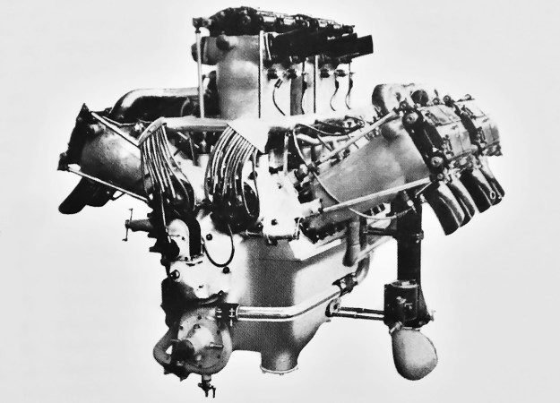
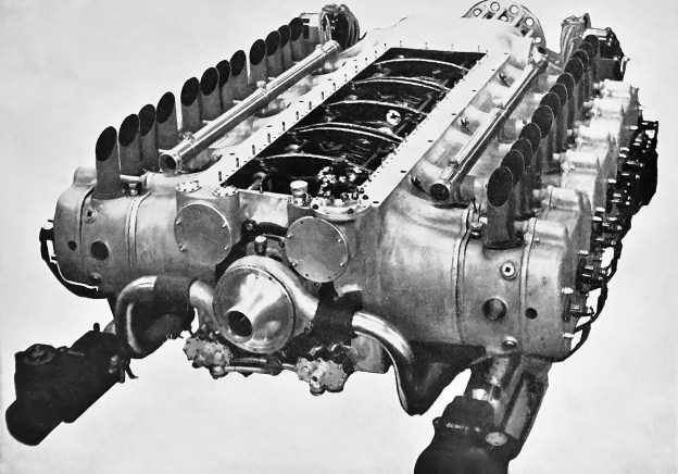
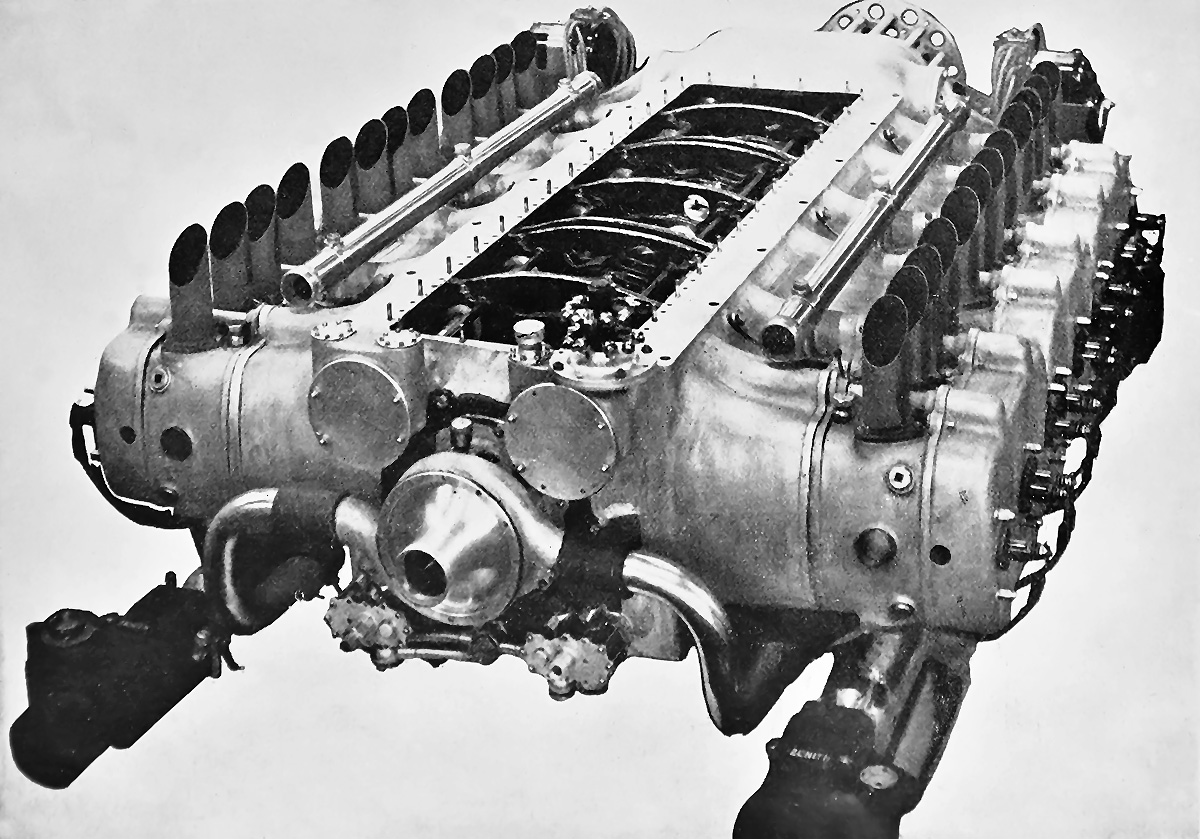
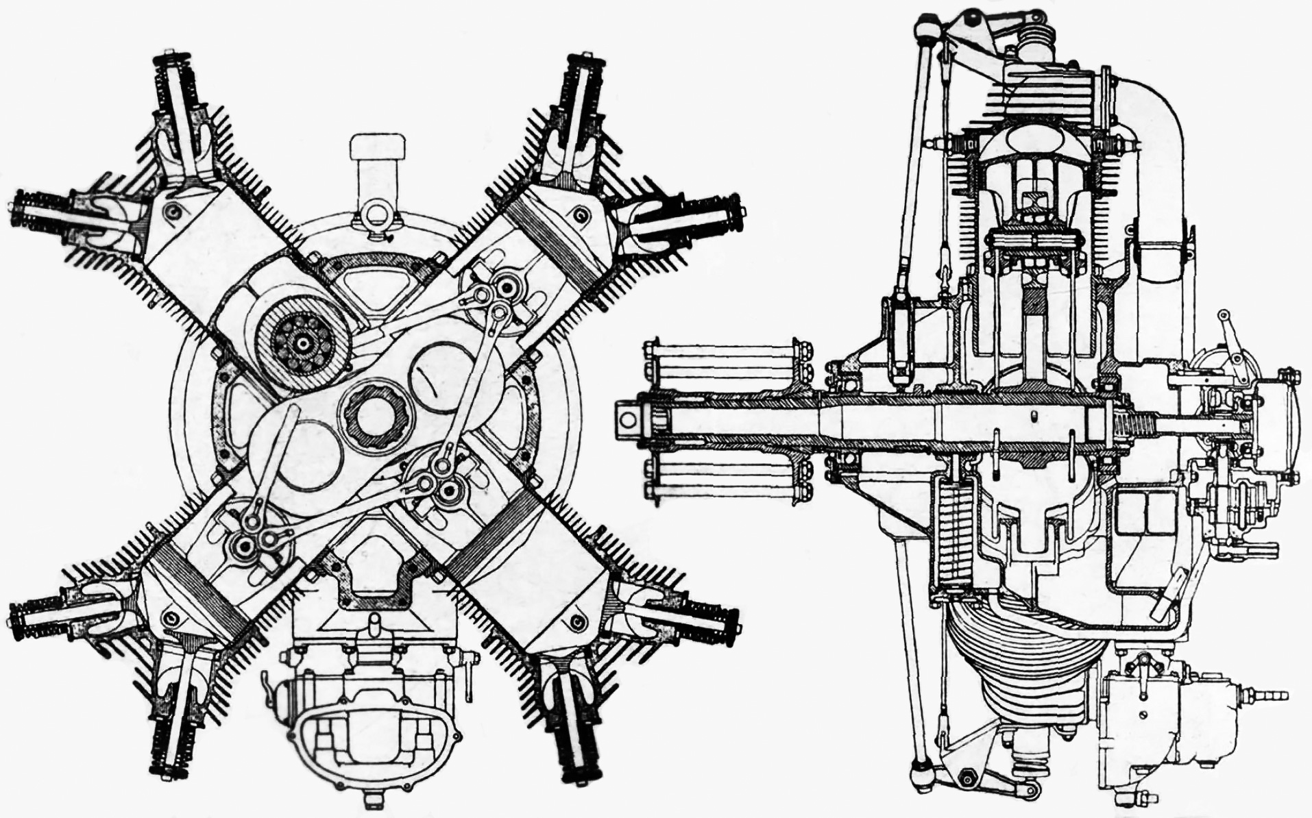
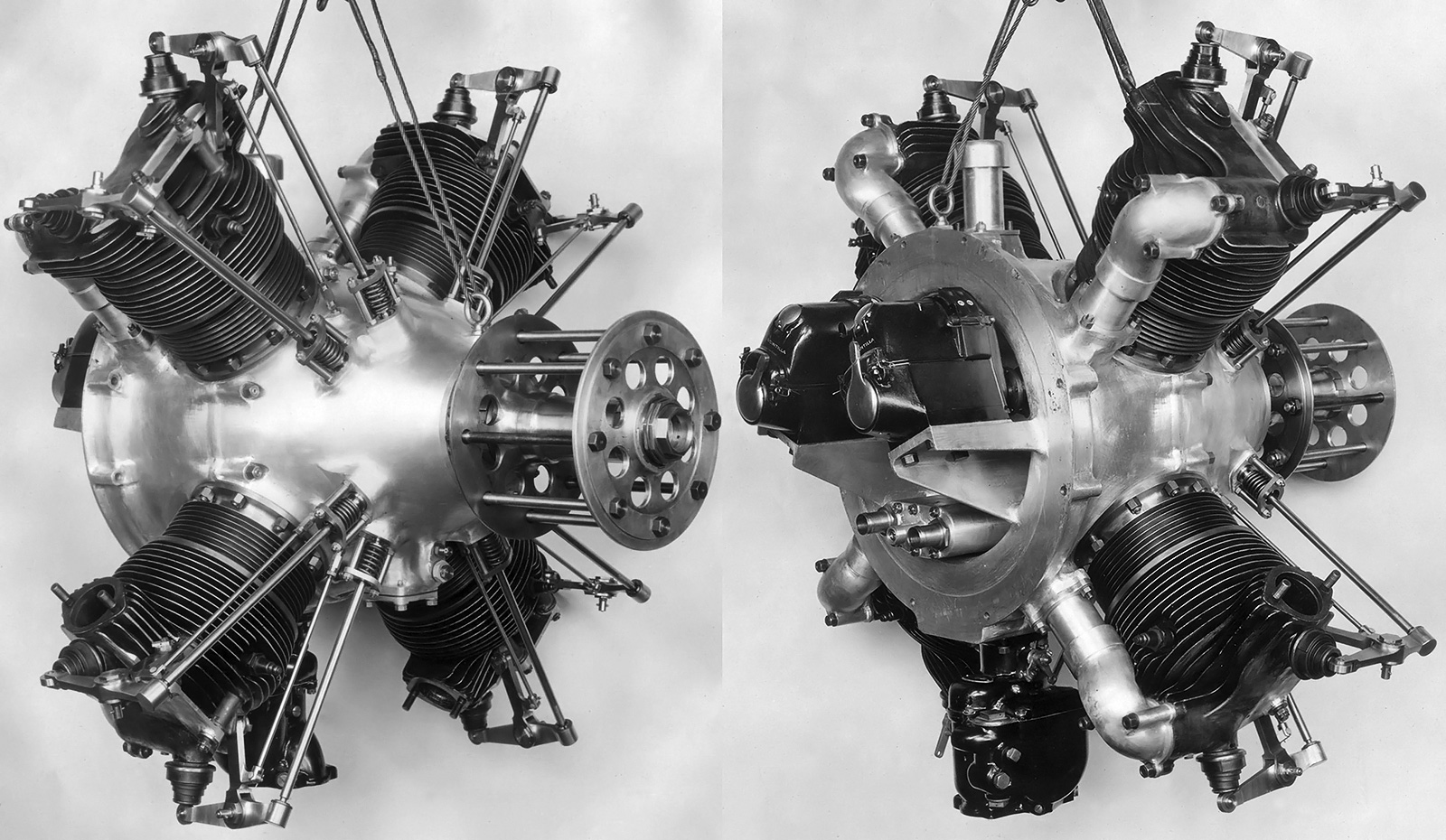
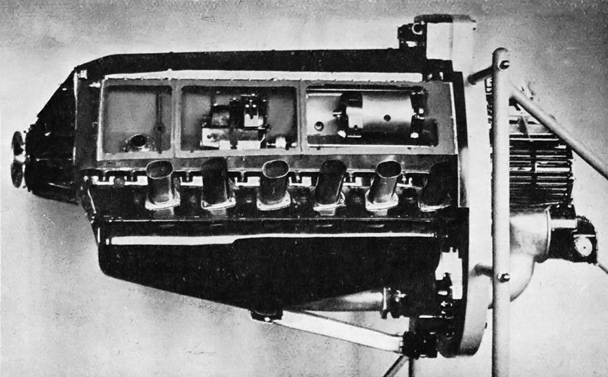
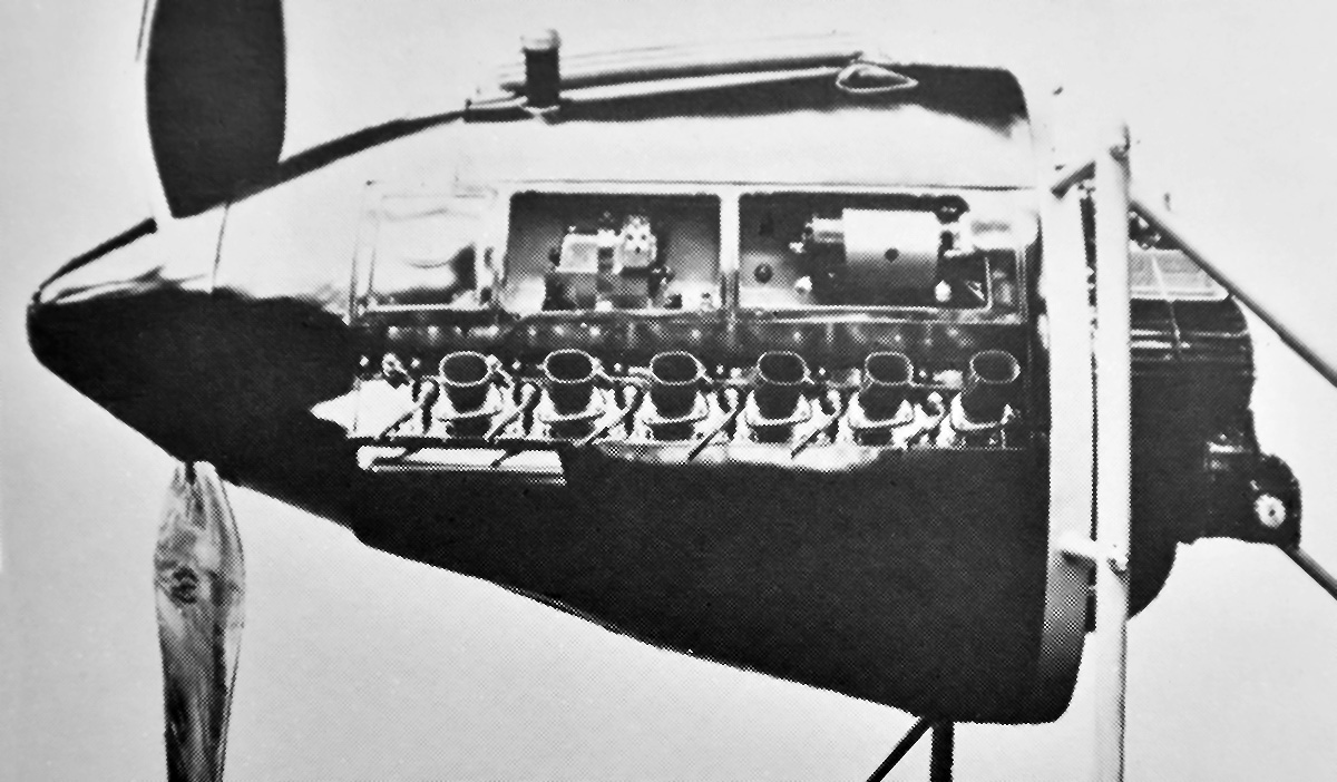
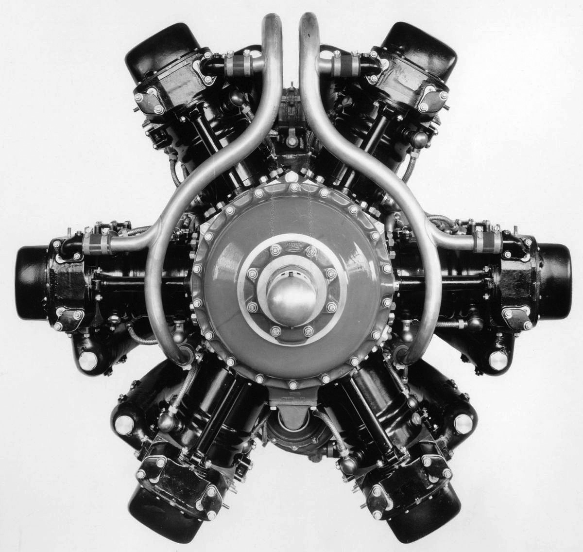
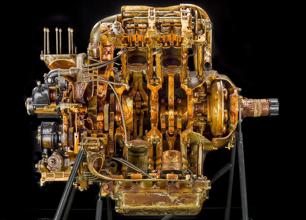
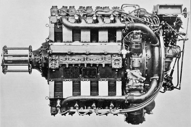
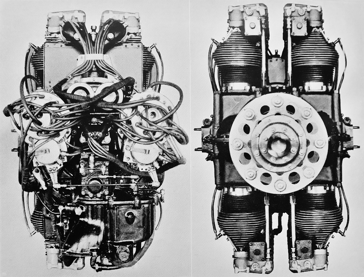
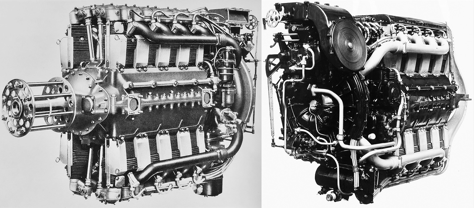
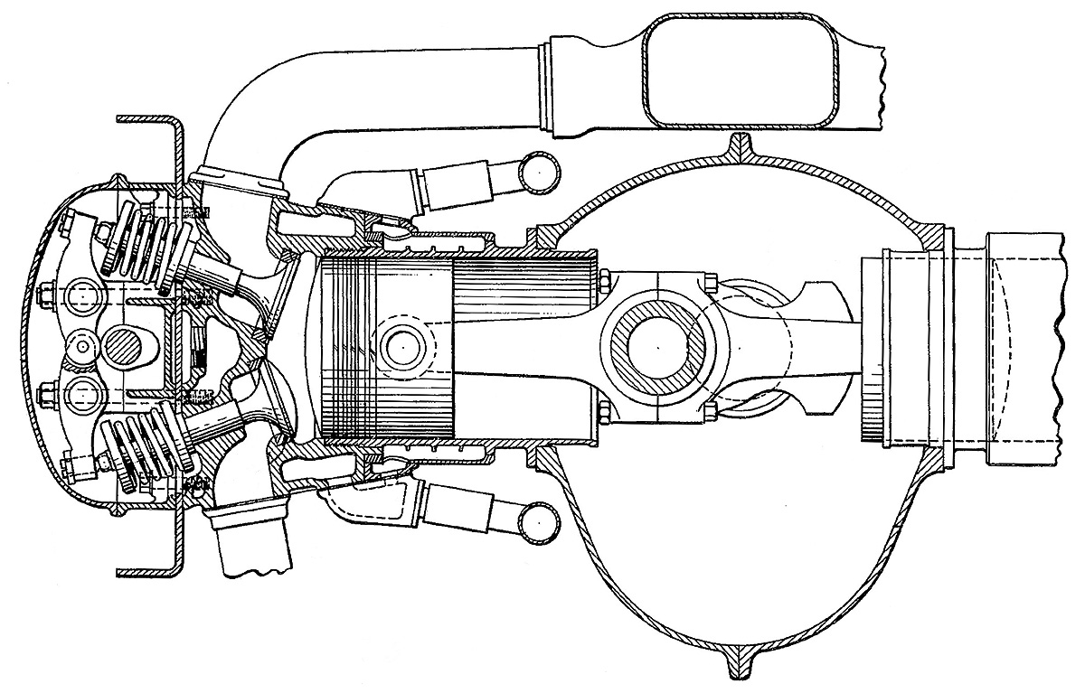
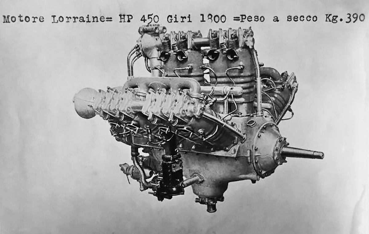
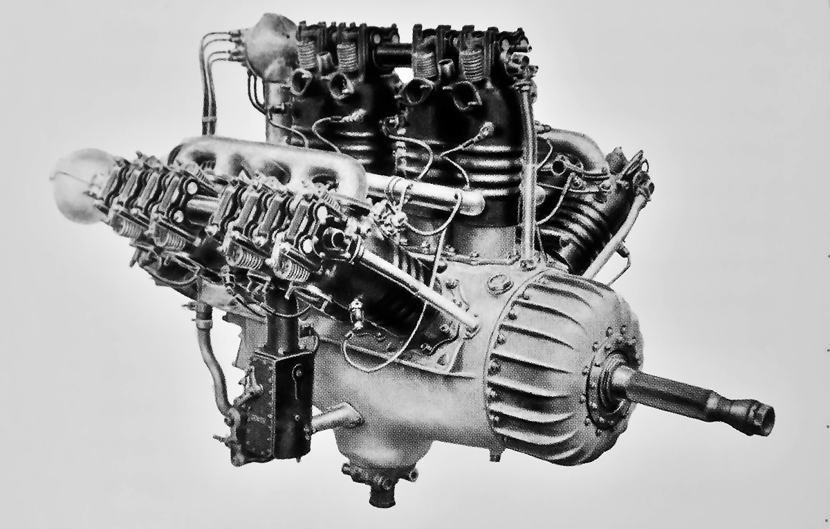
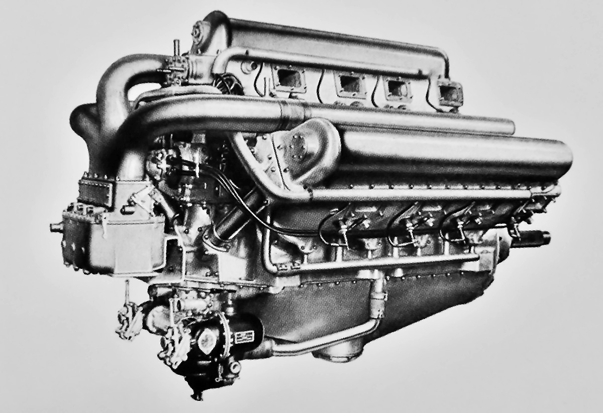
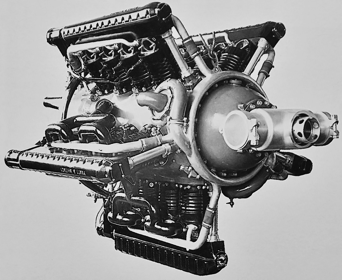
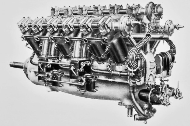
The Lorraine 12F of 1919 was the first of the company’s W-12 engines and followed the design outlined in the 1918 patent. Note the exposed pushrods and enclosed valves.

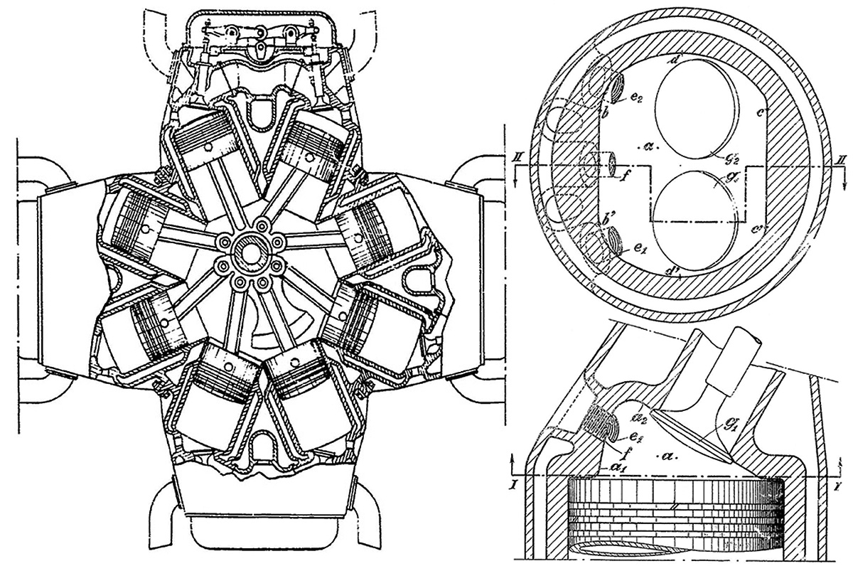
By 1918, Lorraine had developed aircraft engines in the form of an inline-six, a V-8, and a V-12. However, Barbarou began to experiment with engines of a W configuration. The W (or broad arrow) engine configuration had the benefit of being more rigid and slightly lighter than a comparable V-12, with the drawback of being slightly taller and wider. On 5 June 1918, Lorraine (under Barbarou) applied for a patent in which the benefits of a W engine with either four, six, or eight cylinders per bank was described. While the British Napier Lion W-12 was being developed at the same time, the patent illustrates that the Lorraine W engines were a parallel development and not a copy of the Lion. French patent 504,772 was awarded on 22 April 1920 for the W engine design.

The first generation of Lorraine’s W engines was designed around 1918 and known as the 12F (many sources do not give a designation for this engine, and “12F” was used again). The liquid-cooled, 12-cylinder engine consisted of a two-piece aluminum crankcase that was split horizontally along the crankshaft’s axis. Three banks of cylinders were mounted atop the crankcase, and the left and right banks were angled 60 degrees from the center, vertical bank. Each cylinder bank had two pairs of two cylinders. Each pair of steel cylinders was surrounded by a welded steel water jacket. Atop each cylinder was a single intake valve and a single exhaust valve. The enclosed valves were each actuated by a partially exposed rocker and a fully exposed pushrod. All of the pushrods were controlled by two camshafts—one positioned in each Vee between the cylinder banks. The push rods that controlled the exhaust valves for the left and right cylinder banks had a lower roller rocker that followed the camshaft.

A single-barrel updraft carburetor was positioned on the outer side of the right cylinder bank. An intake pipe led from the carburetor, passed between the two cylinder pairs of the right bank, and joined a manifold. The manifold split into four branches that fed each of the cylinders on the right bank. Employing a similar configuration, a two-barrel carburetor on the left side of the engine fed both the left and center cylinder banks. Each cylinder had two spark plugs that were fired by two magnetos located at the rear of the engine. The left magneto fired the spark plugs on the intake side of the cylinders, and the right magneto fired the exhaust-side spark plugs.

Lorraine 24G

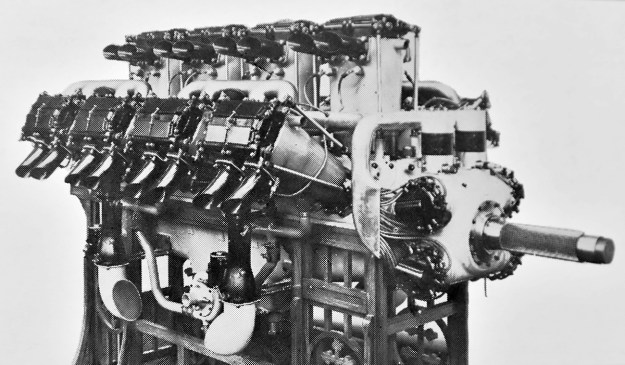
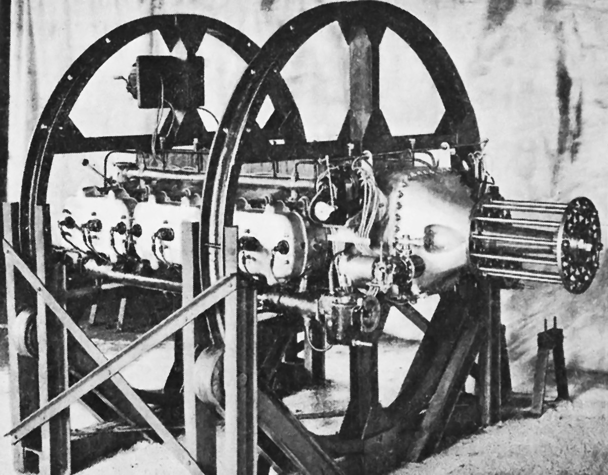
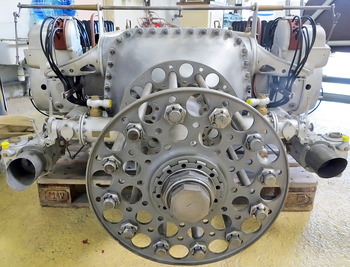
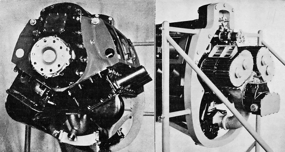
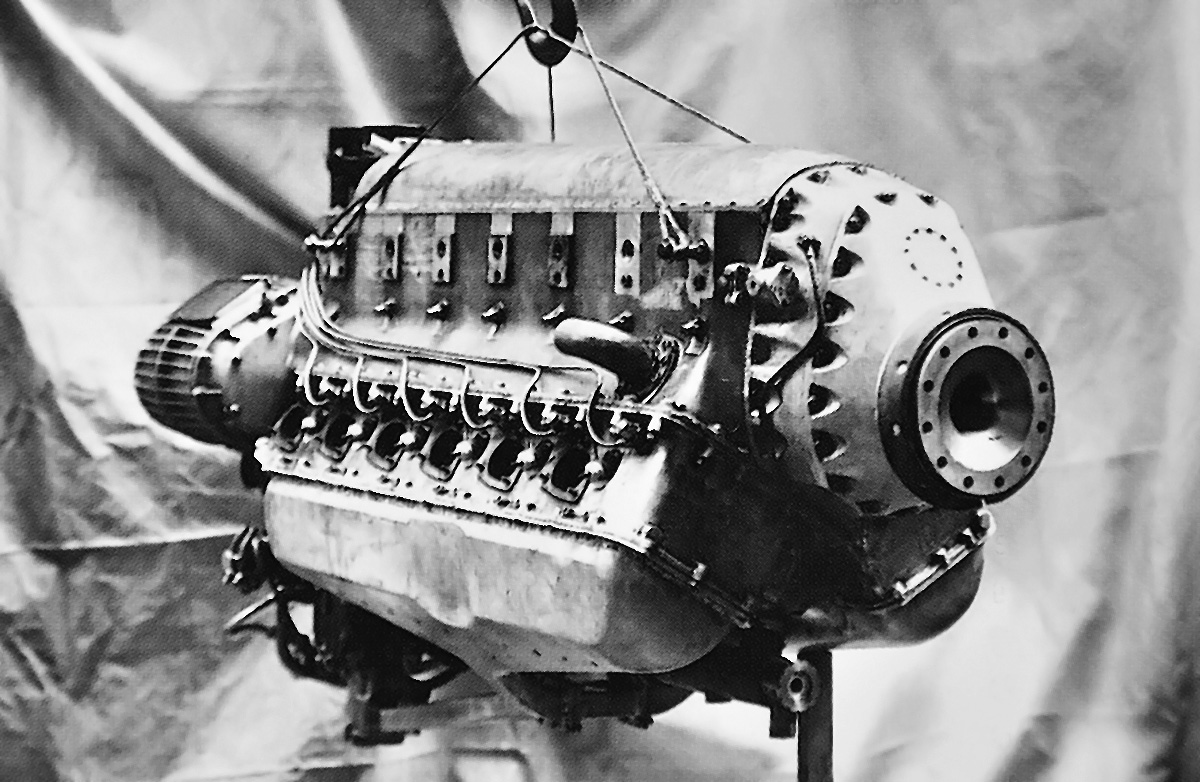
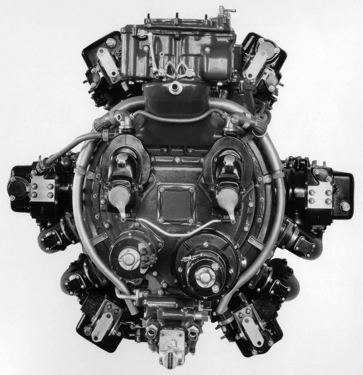
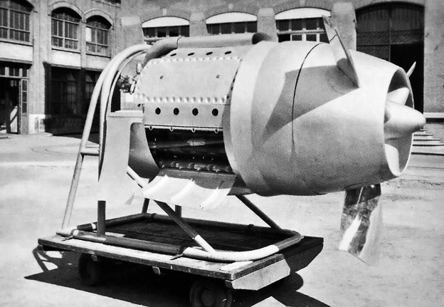
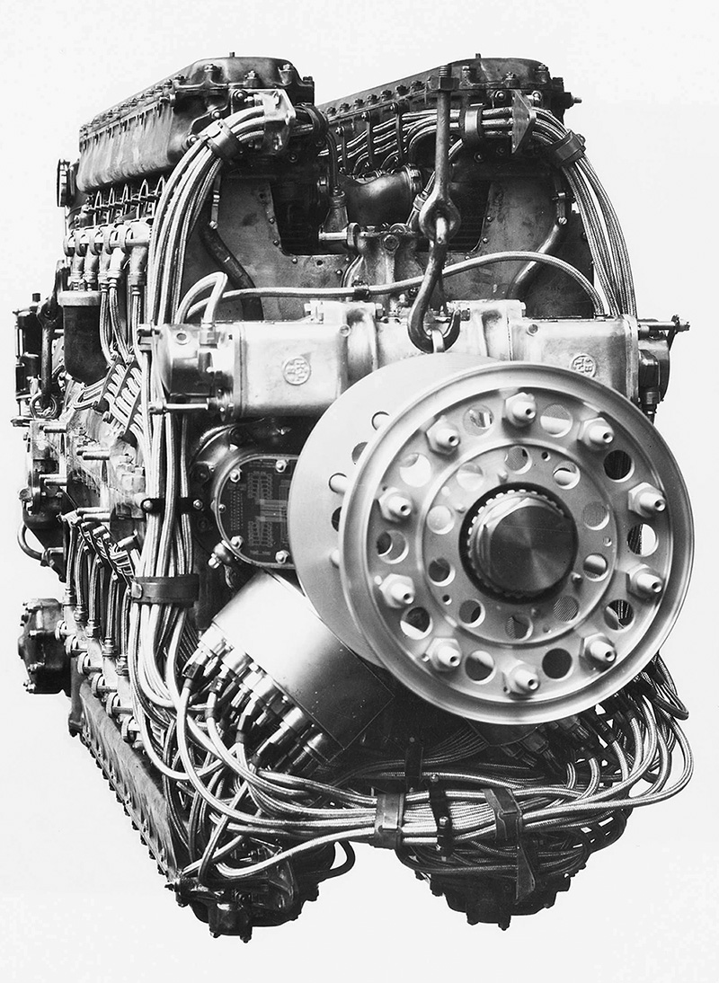
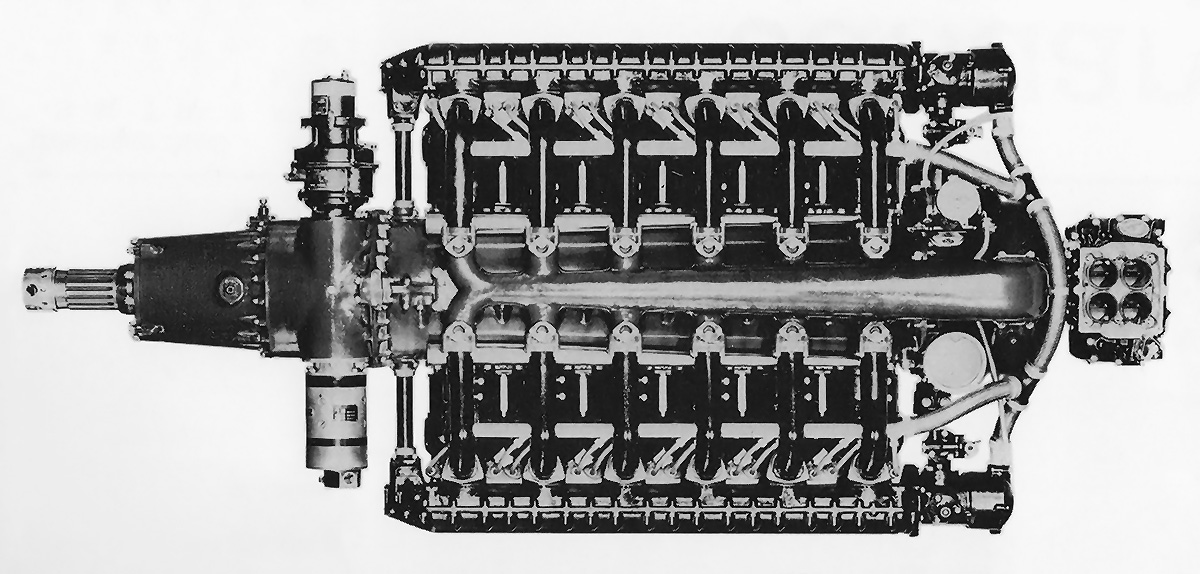
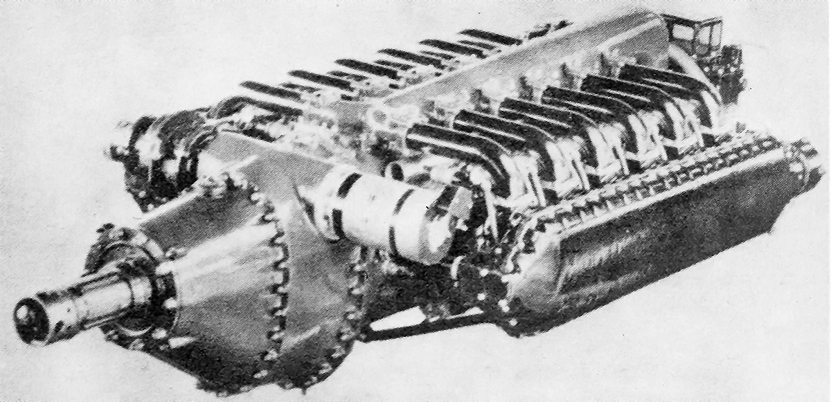
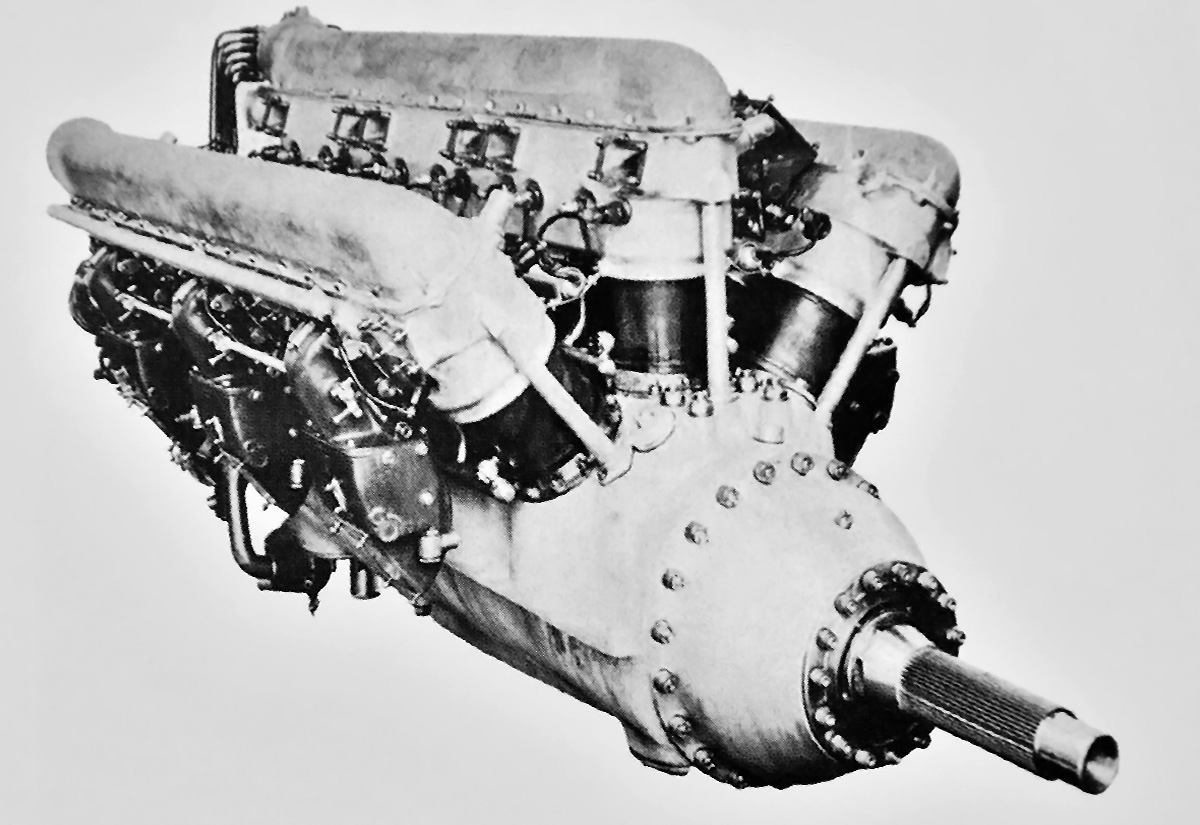
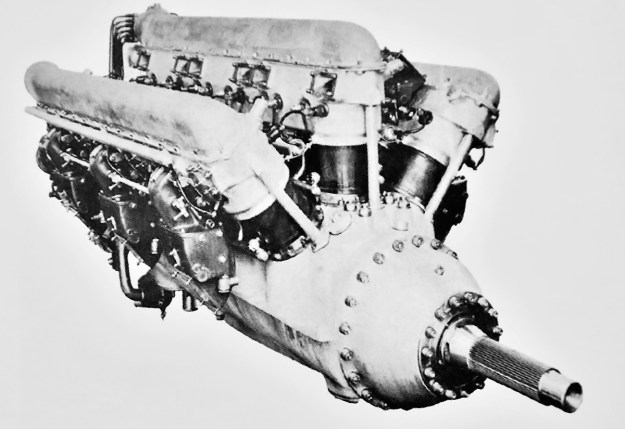
With a new crankcase, crankshaft, and camshafts, the 24-cylinder 24G of 1919 was more than just two 12F engines coupled together. Note the ignition system driven from the propeller shaft.

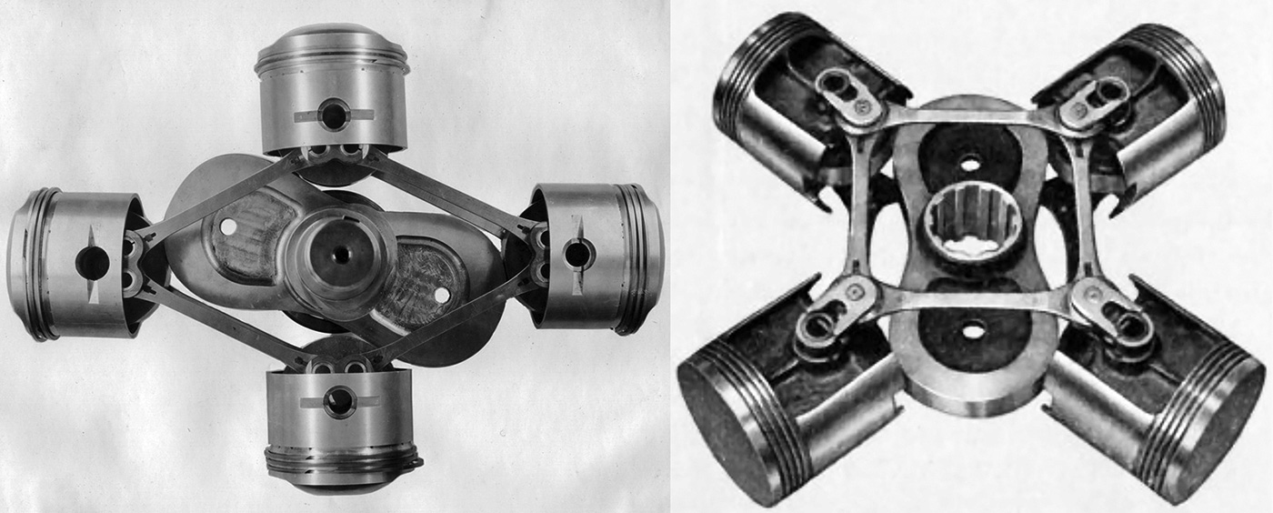
The flat-plane crankshaft had four throws and was supported by three main bearings. A master connecting rod was attached to each crankpin. The master rods were connected to the aluminum pistons in the vertical cylinder bank. Articulated rods connected the pistons in the left and right cylinder banks to the master connecting rods. The engine had a compression ratio of 5.2 to 1. The propeller was attached directly to the crankshaft without any gear reduction. The Lorraine 12F had a 4.96 in (126 mm) bore and a 7.09 in (180 mm) stroke. The W-12 engine displaced 1,826 cu in (29.9 L) and produced 500 hp (372 kW) at 1,600 rpm. The 12F weighed 960 lb (435 kg).

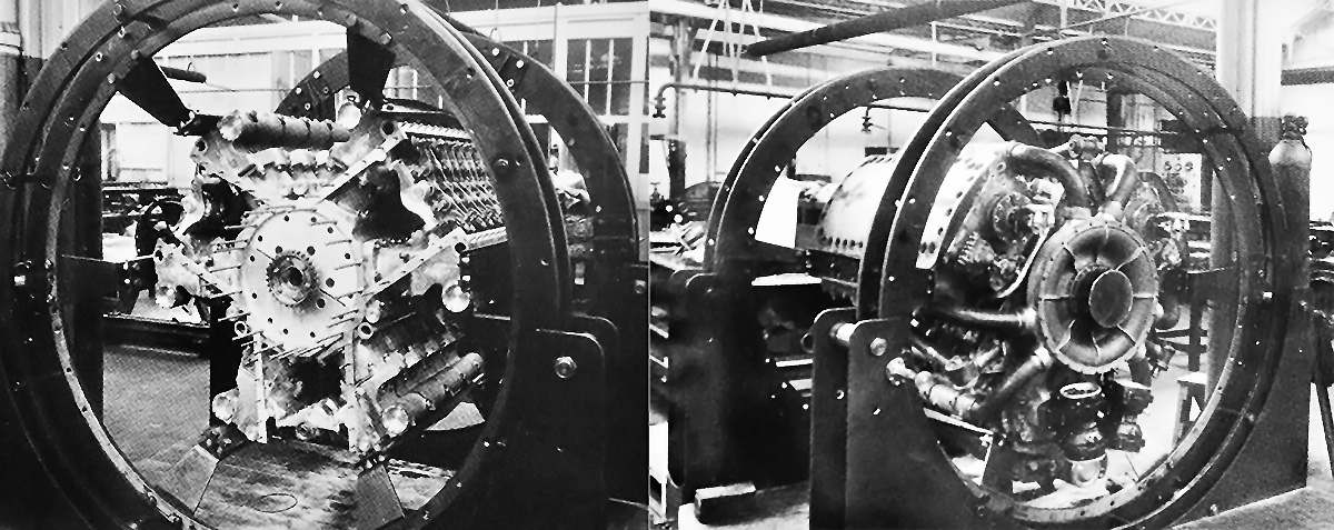
While work on the 12F was underway, a 24-cylinder engine was designed that was basically two 12Fs. The W-24 engine was designated 24G (many sources do not give a designation for this engine, and a different G-series emerged later). Other than having twice the number of cylinders, the main change from the 12F was that the ignition system was driven at the front of the engine. The 12G’s eight throw crankshaft was supported by five main bearings. The W-24 engine displaced 3,652 (59.9 L) and produced 1,000 hp (746 kW) at 1,600 rpm. The direct drive engine weighed 1,874 lb (850 kg), and it was estimated that a 16 ft 5 in (5 m) propeller would be needed to harness its power.

The 12F and 24G engines were built during 1919 and displayed at the Salon de Paris in December of that year. There is some indication that the valve arrangement was problematic at high engine speeds, but the engines were displayed at the next two Salons in November 1921 and December 1922. No applications are known for the 12F or the 24G, which were too large for almost all aircraft. It is unlikely that more than a few of these engines were built.

Lorraine 12Eb no mags

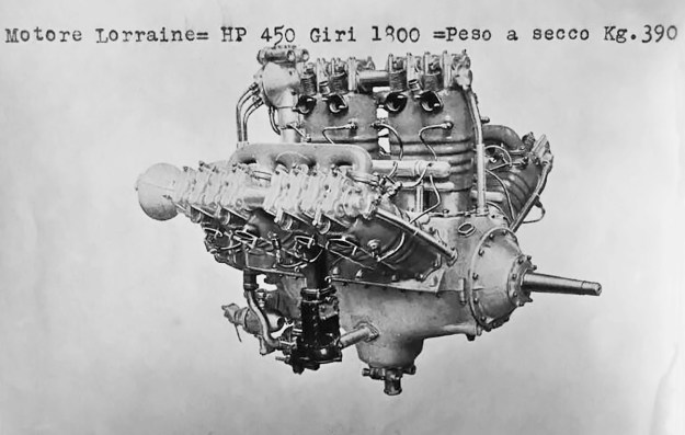
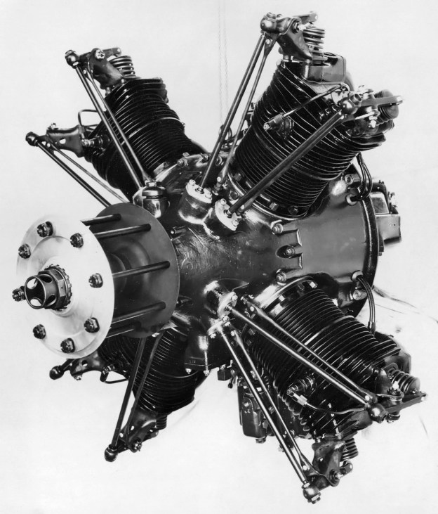
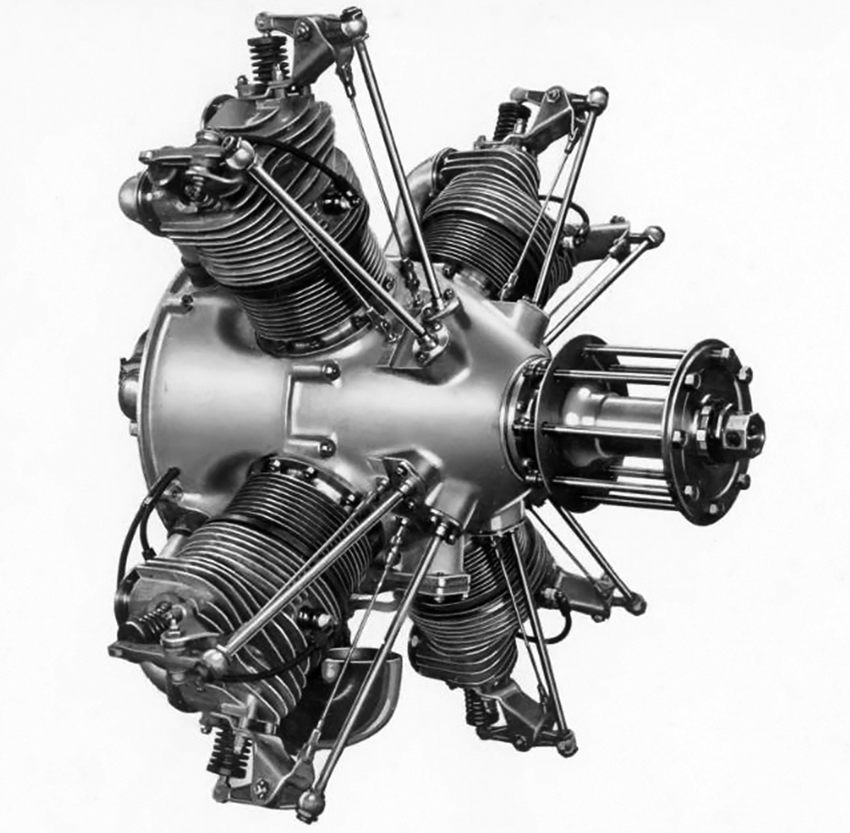
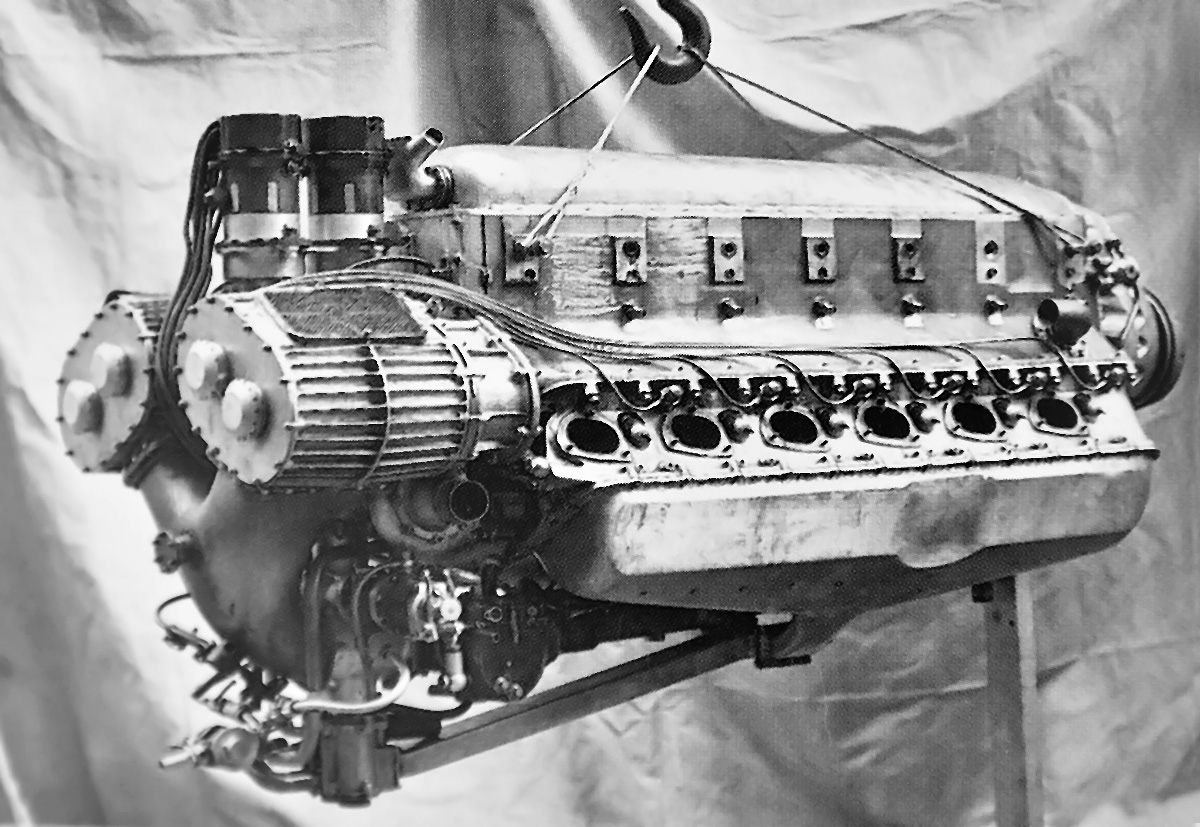
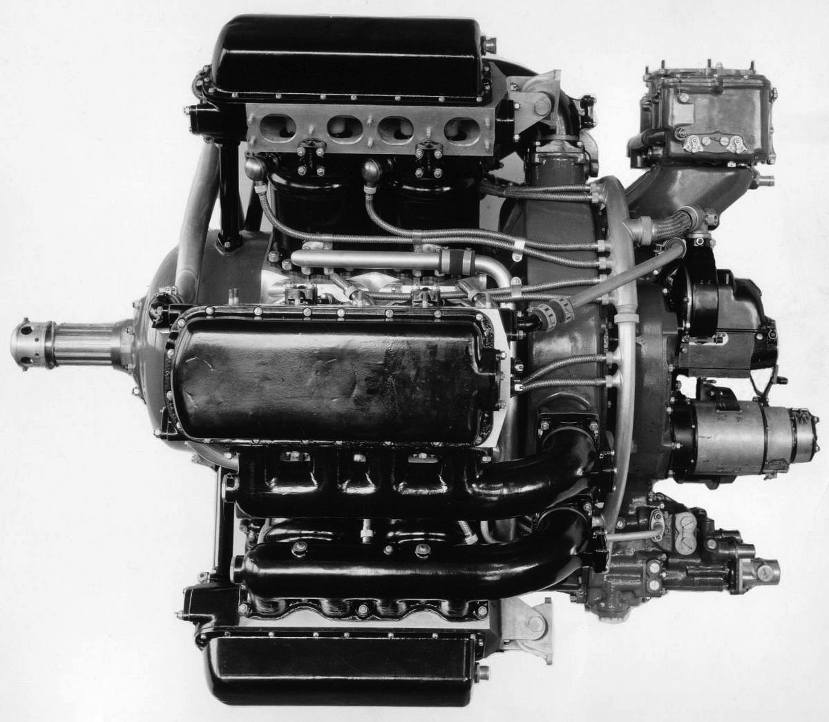
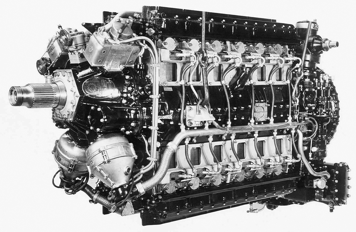
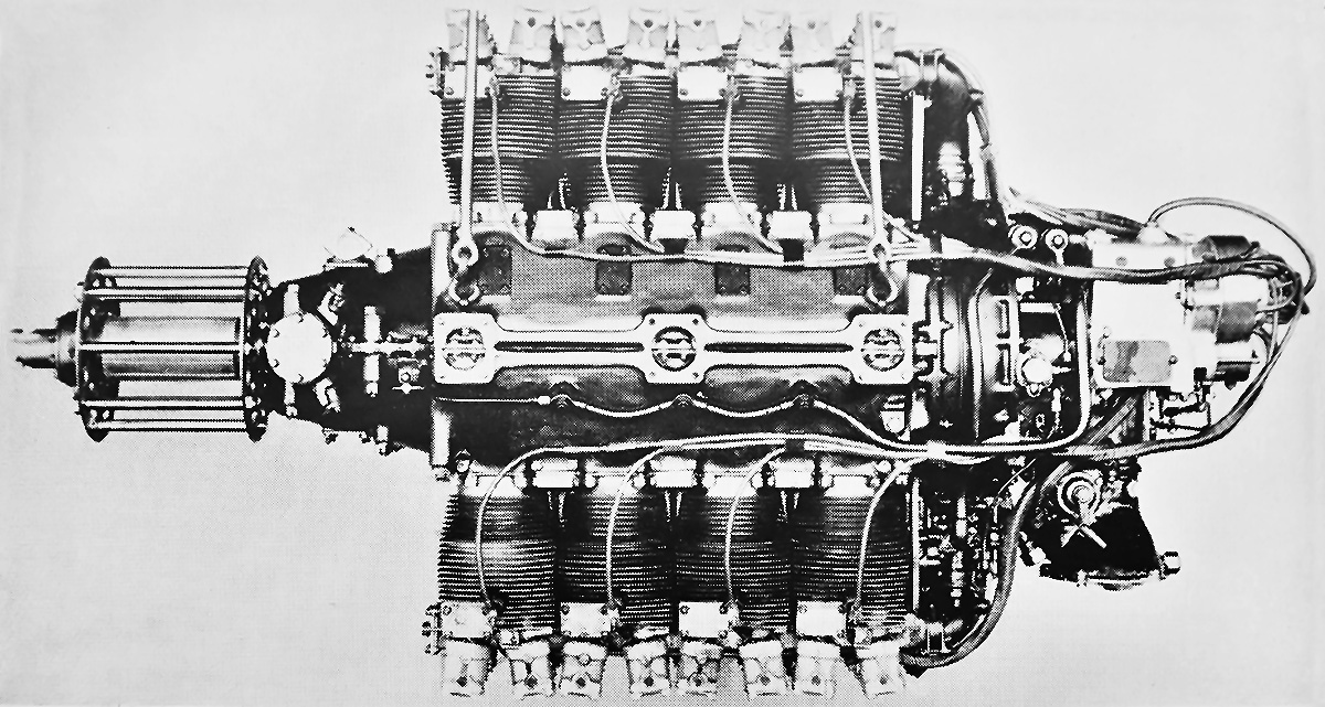
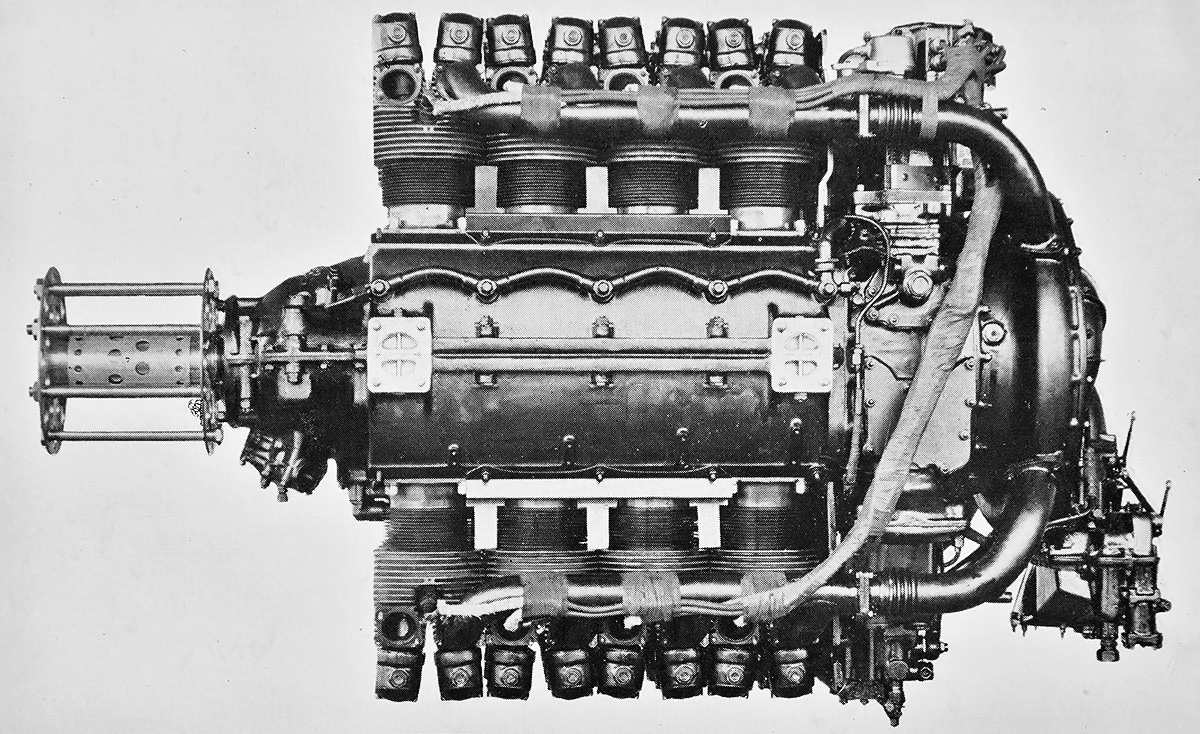
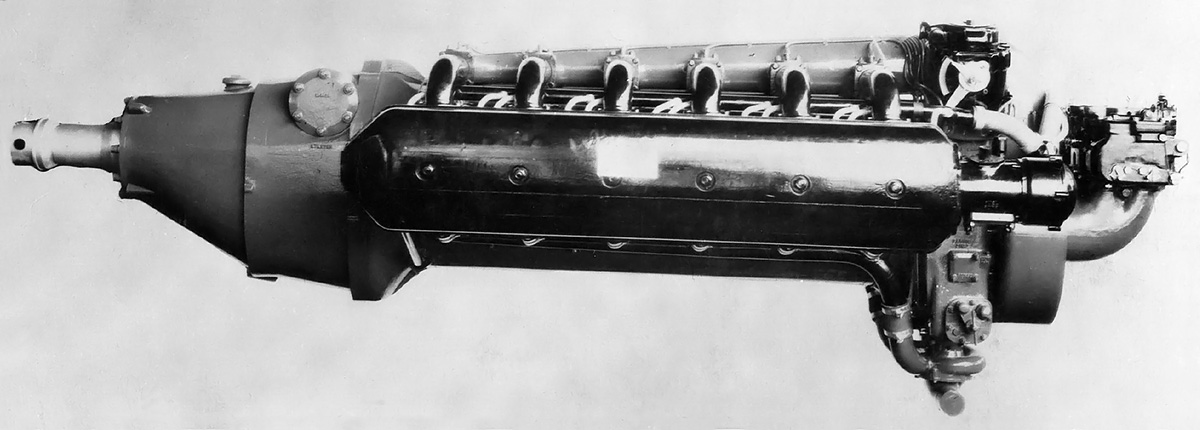
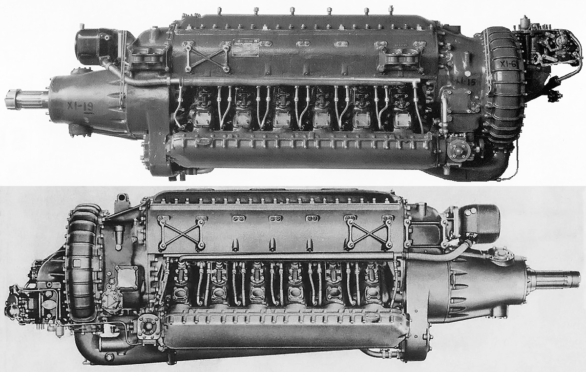
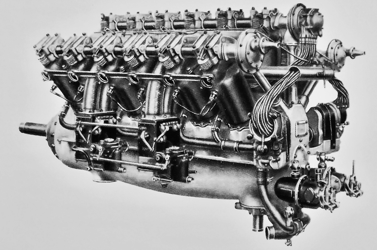
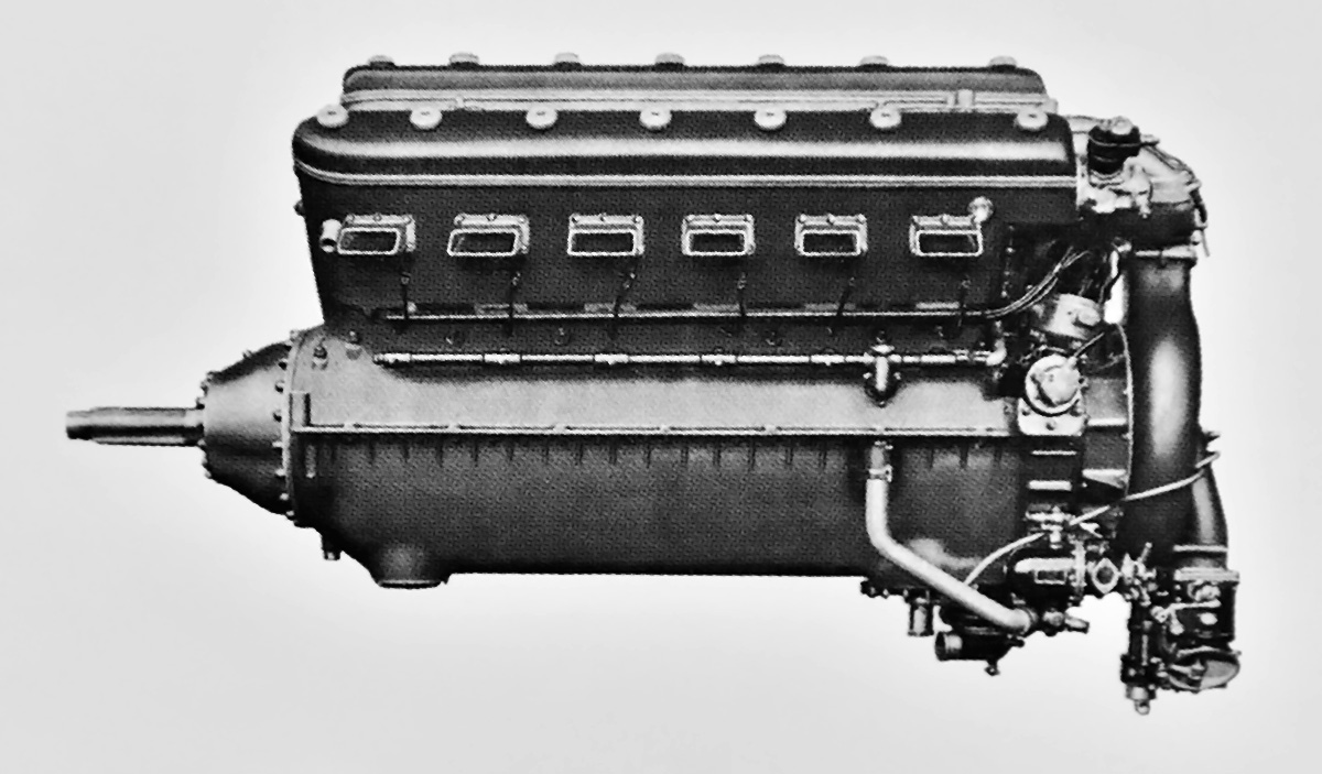
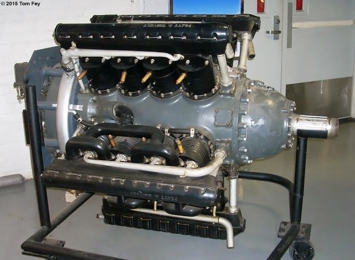
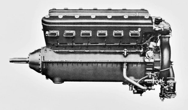
A direct-drive 12E-series engine with exposed valves and overhead camshafts. Unseen are the magnetos positioned at the rear of the engine.

While enduring the rough start with the first generation of W engines, Barbarou had already designed the second generation—starting with the 12E-series. The first engine in this series was the 12Ew, which was derived from the 370 hp (276 kW) Lorraine 12D (V-12) and conceived to fill the power gap between that engine and the 500 hp (373 kW) 12F. The 12Ew was similar in layout to the 12F, but had a completely different valve arrangement. The exposed valves for each cylinder bank were actuated via rockers by a single overhead camshaft. The camshaft was driven by the crankshaft via bevel gears and a vertical shaft at the rear of the engine. It appears that the two magnetos were initially located at the front of the engine but later relocated to the rear of the engine. The engine had a compression ratio of 5.5 to 1. The propeller was attached directly to the crankshaft without any gear reduction.

The Lorraine 12Ew had a 4.72 in (120 mm) bore and a 7.09 in (180 mm) stroke. The engine displaced 1,491 cu in (24.4 L) and produced 420 hp (313 kW) at 1,800 rpm. The 12Ew was 54.1 in (1.37 m) long, 47.6 in (1.21 m) wide, and 44.8 in (1.14 m) tall. The engine weighed around 860 lb (390 kg). The 12Ew was first run around late 1919, but development was slowed due to work on other engines and other projects. The 12Ew was used in a few aircraft, and the engine was developed into the 12Eb.

The Lorraine 12Eb was dimensionally the same as the 12Ew, but it had a compression ratio of 6.0 to 1 and produced 450 hp (336 kW) at 1,850 rpm. The engine weighed 822 lb (373 kg). The 12Eb was first run in late 1922 or early 1923, and 30 test engines were built in 1923. The 12Eb quickly proved itself to be a successful engine. In March 1924, the 12Eb was the most economic engine at an endurance competition (Concours de Moteurs de Grande Endurance) held at Chalais-Meudon, near Paris. The engine operated for a total of 410 hours at 1,850 rpm. During that time, three cylinders were replaced due to water leaks.

Lorraine 12Eb museaum

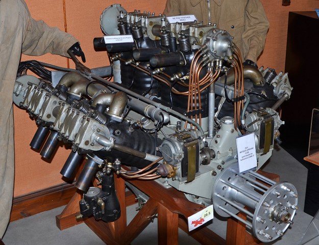
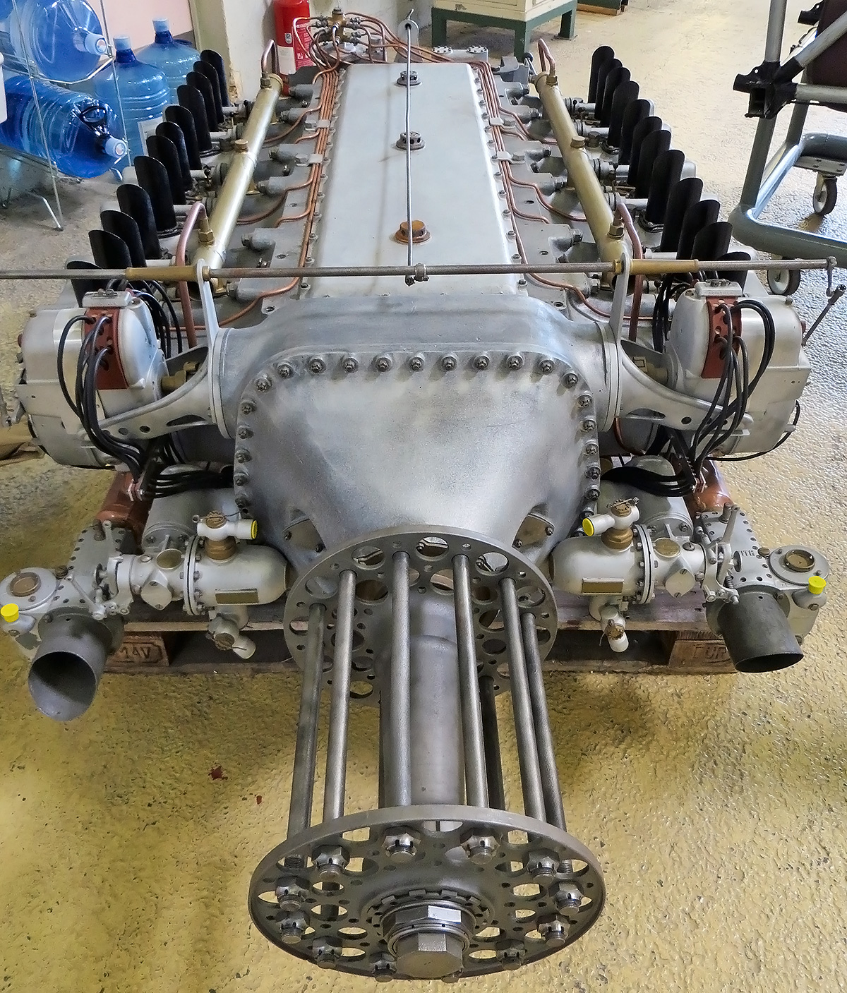
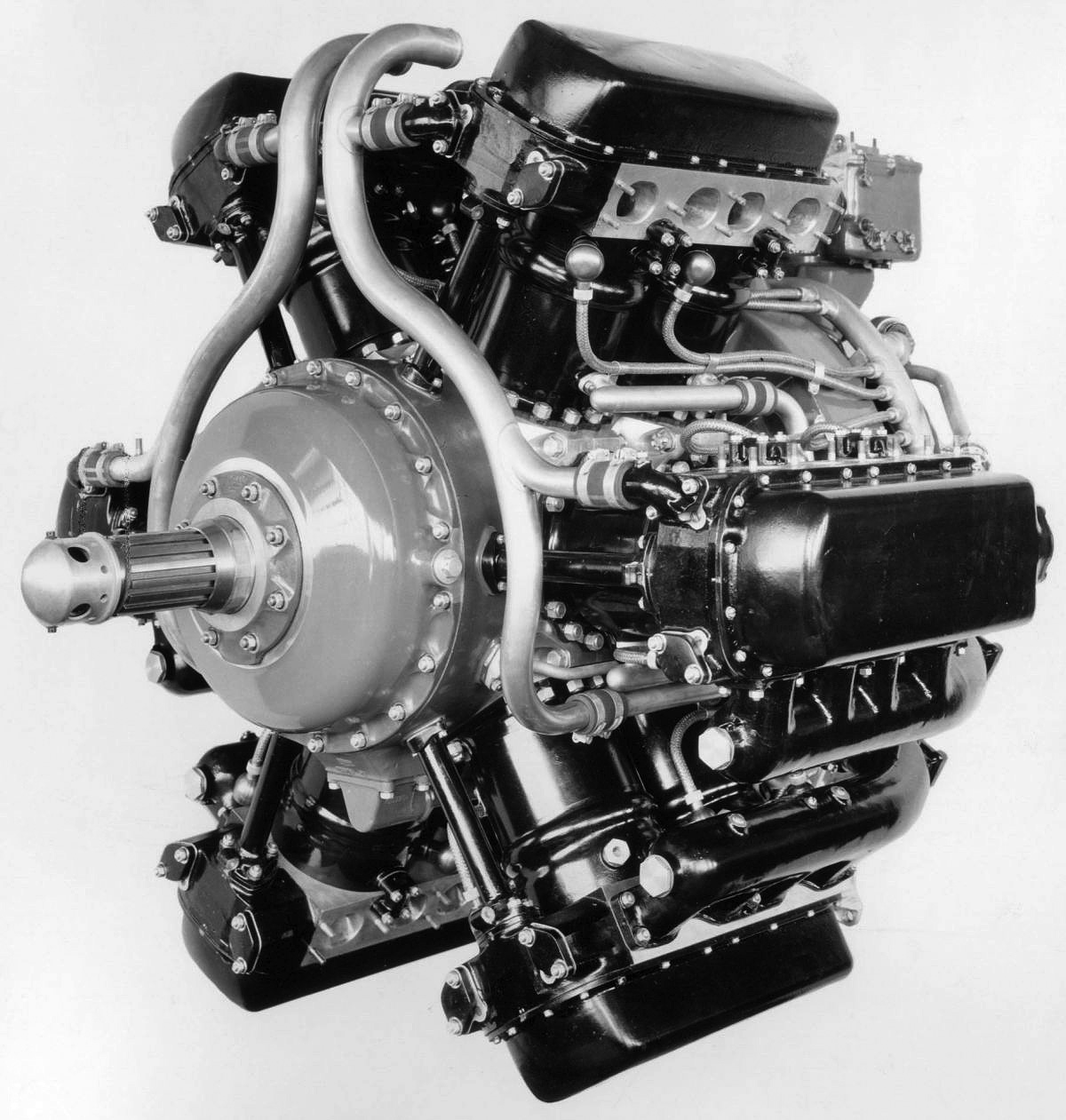
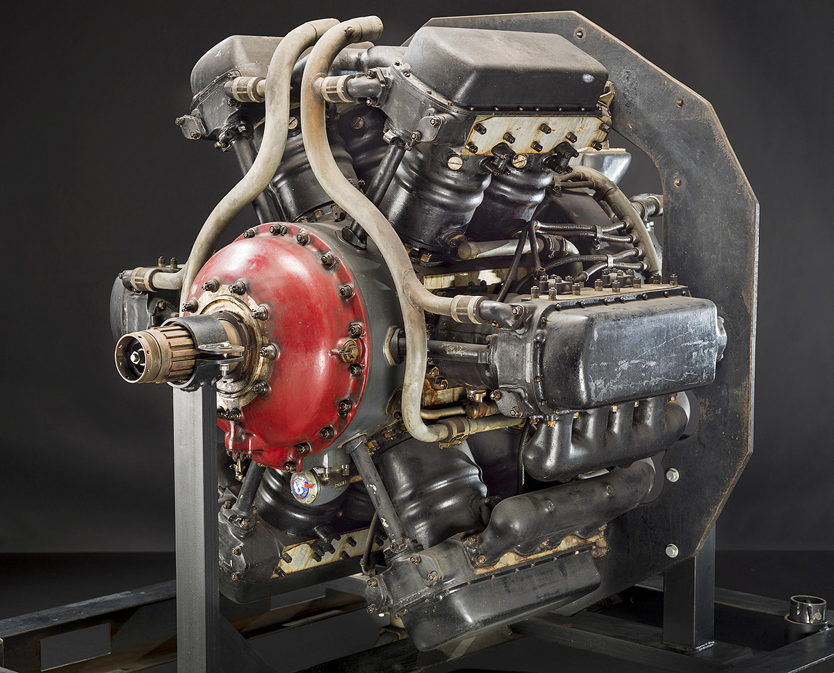
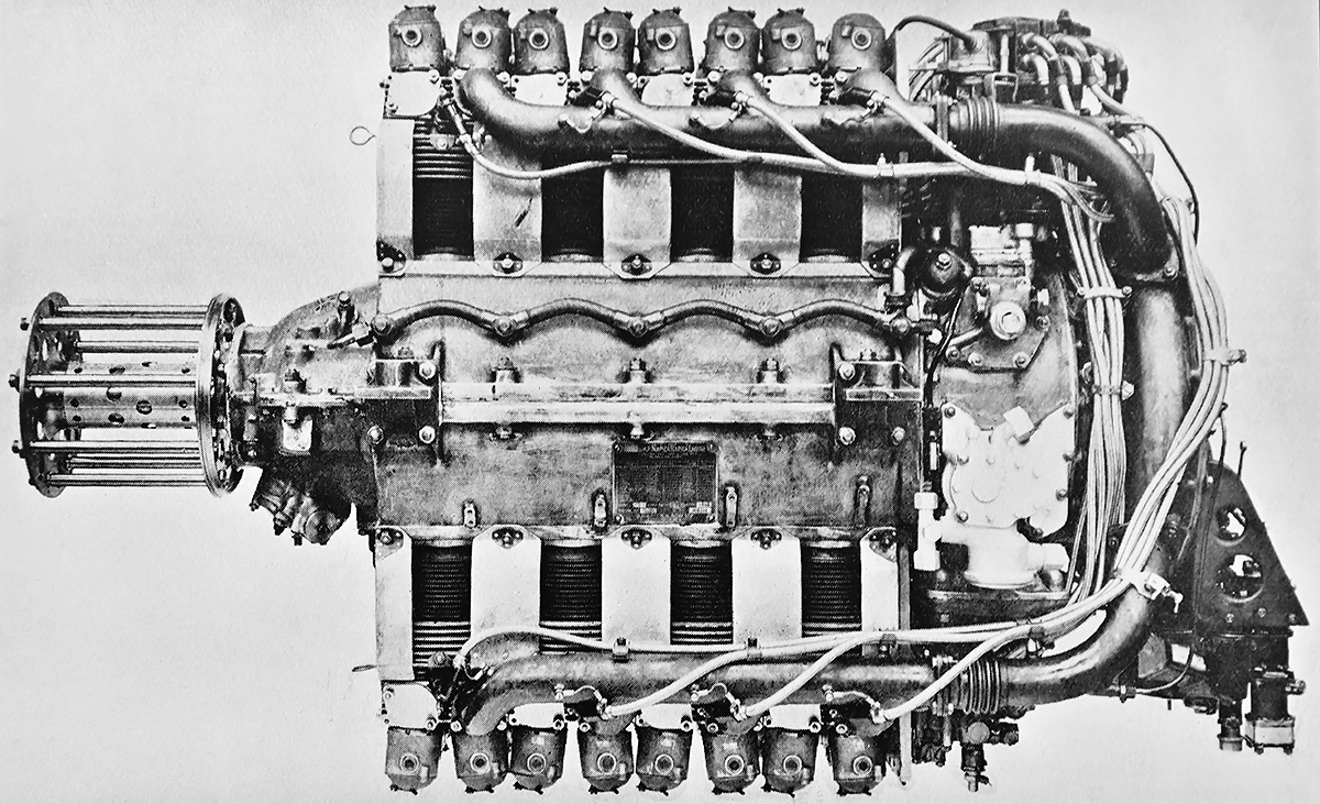
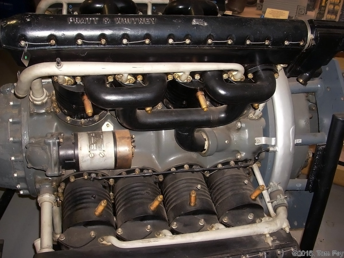
A 12Eb engine with the magnetos driven from the front of the engine. Power from the magnetos was taken to the distributors, which were driven by the back of the left and right cylinder bank camshafts. (Pline image via Wikimedia Commons)

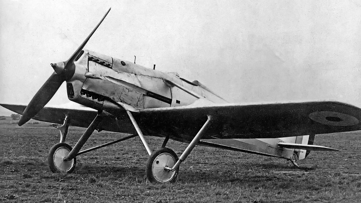
12Eb production started in late 1924, and approximately 150 engines were built in 1925. From 1924 to 1927, a number of licenses were purchased by other countries to manufacture the 12Eb: CASA and Elizalde in Spain; SCAT in Italy; FMA in Argentina; Hiro, Nakajima, and Aichi in Japan; PZL in Poland; Škoda and ČKD in Czechoslovakia; and IAR in Romania. The Blériot-SPAD S.61 fighter, the Breguet 19 light bomber, and the Potez 25TOE reconnaissance bomber were the 12Eb’s primary applications.

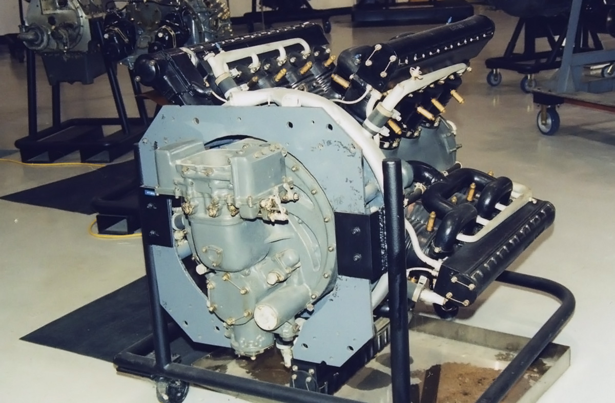
In 1925, a geared version of the 12Eb was developed, and it was designated 12Ed (sometimes referred to as 12Ebr). The planetary gear reduction turned the propeller at .647 times crankshaft speed. At 59.9 in (1.52 m), the 12Ed was 5.8 in (.15 m) longer than the direct-drive engine. Engine weight also increased 86 lb (39 kg) to 908 lb (412 kg). The 12Ed produced the same 450 hp (336 kW), but this was achieved at 1,900 engine rpm and 1,226 propeller rpm. The main application for the 12Ed was the CAMS 37 reconnaissance flying boat.

Lorraine 12Ed

The 12Ed engine with a propeller gear reduction was the same basic engine as the 12Eb. The early engines had a smooth gear reduction housing, but ribs were added later for extra strength.

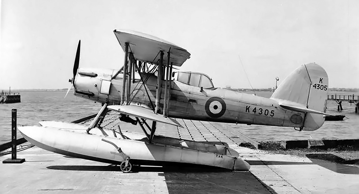
The 12Ee debuted in 1926. This engine was basically a 12Eb with its compression ratio increased to 6.5 to 1. The 12Ee produced 480 hp (358 kW) at 2,000 rpm and had a maximum output of 510 hp (380 kW). The engine weighed 846 lb (383 kg). The 12E-series engines were used in the FBA-21 flying boat and Villiers IV seaplane to set numerous seaplane payload and distance records. Lorraine built around 5,500 E-series W-12 engines, and licensed production added another 1,775, for a total of approximately 7,275 engines. In all, the 12E-series engines were used in around 24 countries.

In December 1926, a Lorraine W-18 engine was displayed at the salon de l’Aviation in Paris. The 18-cylinder engine was designated 18K, and it was based on the E-series. The engine had been under development by Barbarou since at least 1923. The 18K had individual cylinders, rather than the paired units used on the E-series. The cylinder banks had an included angle of 40 degrees. Each of the cylinder banks had two carburetors, with each carburetor feeding three cylinders. Otherwise, the induction system was similar to that used on the 12E, including the two barrel carburetors on the left side of the engine for the left and center cylinder banks. The 18K had a compression ratio of 6.0 to 1, and its crankshaft was supported by seven main bearings.

The Lorraine 18K had the same 4.72 in (120 mm) bore and a 7.09 in (180 mm) stroke as the 12E-series engines. The W-18 engine displaced 2,236 cu in (36.6 L) and weighed around 1,287 lb (584 kg). The 18Kb was the direct drive variant that produced 650 hp (485 kW) at 2,000 rpm. The engine was 79.2 in (2.01 m) long, 36.2 in (.92 m) wide, and 43.3 in (1.10 m) tall.

Lorraine 18K

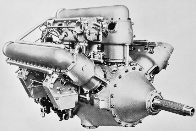
The 18K engine had the same construction as the 12E engines but used individual cylinders. Note that each carburetor fed two inductions pipes—one supplied the left cylinder bank and the other the center bank. The two one-piece magneto/distributor units are driven from the camshaft drive.

A version with a propeller gear reduction was designated 18Kd. The 18Kd turned the propeller at .647 times crankshaft speed and produced up to 785 hp (585 kW) at 2,500 rpm, but its continuous rating was the same as the 18Kb. With a total length of 83.5 in (2.12 m), the 18Kd was 4.3 in (109 mm) longer than the direct drive variant. The 18Kd weighed 1,365 lb (619 kg).

The 18Kd underwent official trials in mid-February 1927, and it was selected for the single-engine Amiot 122 bomber. The 18K may have been installed in other prototype aircraft, but the Amiot 122 was its only production application. A total of approximately 100 18Kb and 18Kd engines were made, and it was not considered a commercial success.

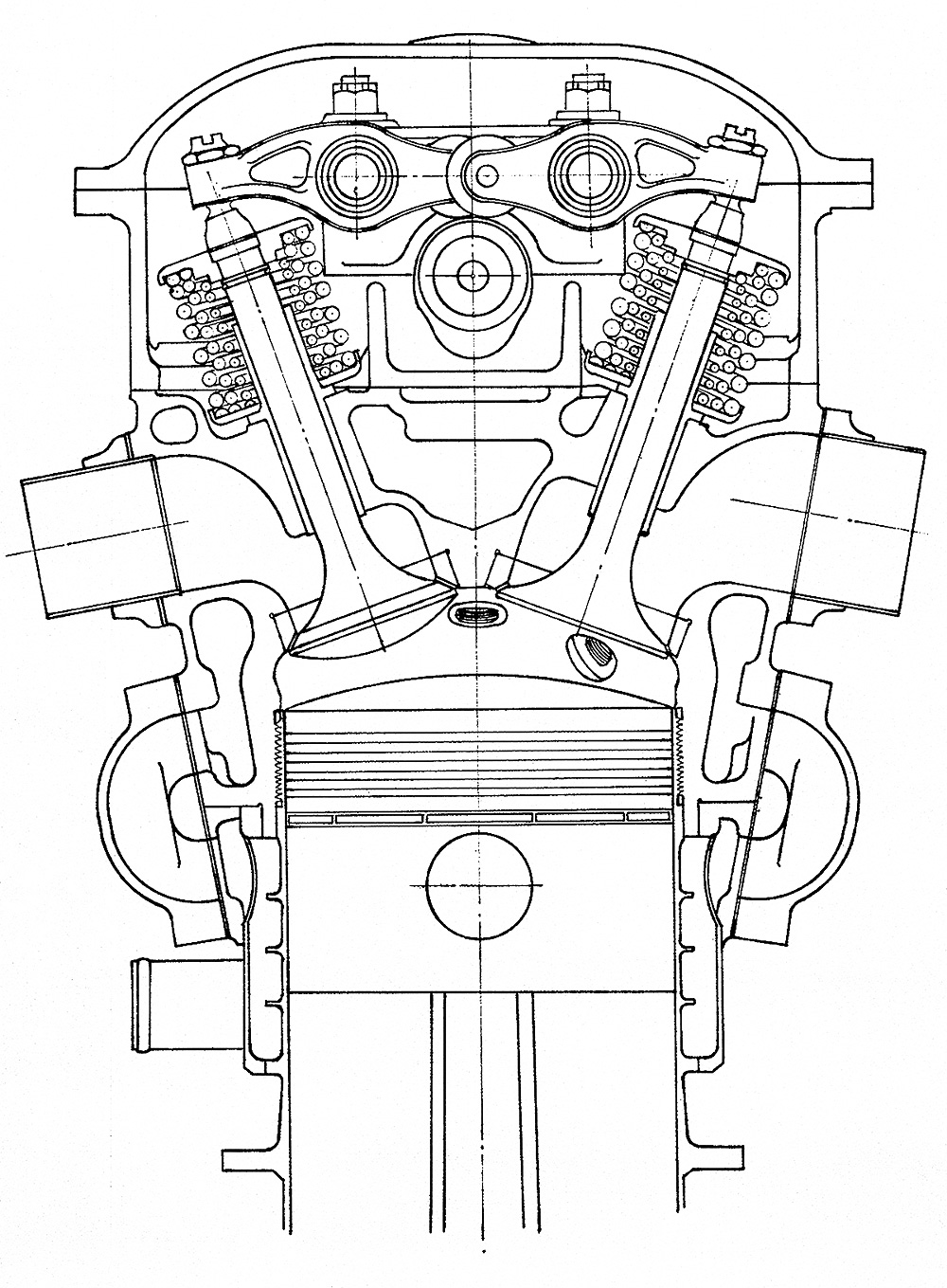
In 1928, Barbarou and Lorraine developed the third generation of W-12 engines, known as 12Fa Courlis. This was a reuse of the “12F” designation that was first applied in 1918. The F-series Courlis engines had a crankcase similar to that of the E-series, but the cylinder bank was a monobloc aluminum casting with enclosed valves. The steel cylinder liners were screwed into the cylinder banks, and the engine’s compression ratio was 6.0 to 1. Compared to the 12E, the cylinder bore diameter was increased, and the stroke length was decreased. Each cylinder had two intake and two exhaust valves, all actuated by a single overhead camshaft. The intake and exhaust ports were on the same side of the cylinder bank, and the carburetors mounted directly to the cylinder bank. The crankshaft was supported by five main bearings.

The Lorraine 12Fa Courlis had a 5.71 in (145 mm) bore and a 6.30 in (160 mm) stroke. The engine displaced 1,944 cu in (31.7 L) and produced 600 hp (447 kW) at 2,000 rpm. Sources indicate that the engine was capable of 765 hp (570 kW) at 2,400 rpm. Without gear reduction, the 12Fa Courlis was 62.2 in (1.66 m) long, 44.9 in (1.14 m) wide, 41.7 in (1.06 m) tall, and weighed 933 lb (423 kg). While the .647 propeller gear reduction did not increase the engine’s length by any noteworthy value, it did add 59 lb (27 kg), resulting in a weight of 992 lb (450 kg).

Lorraine 12Fa

With its enclosed valves and monobloc cylinder banks, the 12Fa Courlis was a modern engine design when it appeared in 1929. The gear reduction mounted to the crankcase in place of the direct-drive propeller shaft housing. The rest of the engine, including the crankshaft, was the same between the direct drive and geared variants.

The 12Fa Courlis was first run around 1928 and was tested by the Ministére de l’Air (French Air Ministry) from 10 to 17 June 1929. During the test, 52 hours were run at 2,000 rpm. In July 1929, the 12Fa made its public debut at the Olympia Aero Show in London. The French authorities officially approved the engine for service on 21 August 1929. The 12Fa was installed in a Potez 25 for engine development tests, which were conducted in 1930.

Developed in 1930, the 12Fb Courlis had a simplified induction system compared to the 12Fa. The 12Fb Courlis had a single, three-barrel carburetor mounted at the rear of the engine. Three separate intake manifolds extended from the carburetor, with one manifold connecting to each cylinder bank. The engine had cross-flow cylinder heads, with the exhaust ports on the side opposite of the intake ports. The 12Fb had the same basic specifications as the 12Fa, but fuel delivery issues initially reduced its rating to 500 hp (372 kW) at 1,900 rpm. However, continued development of the 12Fb soon brought its power up to 600 hp (447 kW) at 2,000 rpm, the same as the 12 Fa. Although installed in a few prototypes, the 12Fb did not power any production aircraft. By the early 1930s, air-cooled radial engines were increasing in popularity for transports and liquid-cooled V-12 engines for fighters. The Lorraine F-series Courlis did not find the success of the E-series. Around 30 F-series Courlis engines were built.

Lorraine 12Fb

The 12Fb had a simplified induction system with one carburetor and three intake manifolds. However, unequal fuel distribution was an issue.

Around 1932, an updated 12Eb was designed that incorporated some features from the 12F-series. Designated 12E Hibis, the engine used aluminum four-valve heads similar to those employed on the 12F engines. The Hibis had a 4.80 in (122 mm) bore and a 7.09 in (180 mm) stroke. The engine’s total displacement was 1,541 cu in (25.3 L), and it produced 500 hp (373 kW) at 2,000 rpm. While the engine was proposed around 1932, it is not clear if any were actually produced. The Hibis had disappeared by 1934.

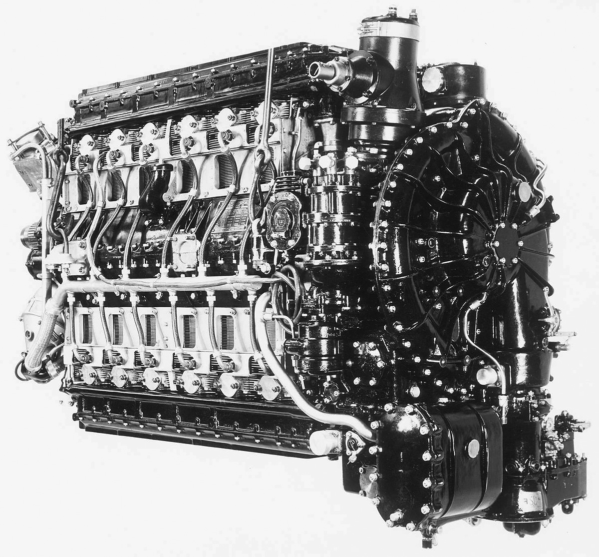
In 1930, Barbarou created the 18-cylinder Lorraine 18Ga Orion. This W-18 engine combined the configuration of the 18K and the improved construction techniques of the F-series Courlis engines. The 18Ga had three monobloc cylinder banks set at 40 degrees. Each bank had six cylinders with a single overhead camshaft that operated the four valves per cylinder. The left and right cylinder banks had their intake and exhaust ports on their outer side. The carburetors were also mounted directly to the outer side of the cylinder bank. The center cylinder banks had a crossflow head with the carburetor and intake ports on the left side and the exhaust port on the right side. The crankshaft was supported by seven main bearings, and the engine had a .647 planetary gear reduction. It does not appear that there was a direct-drive variant.

Lorraine 18Ga

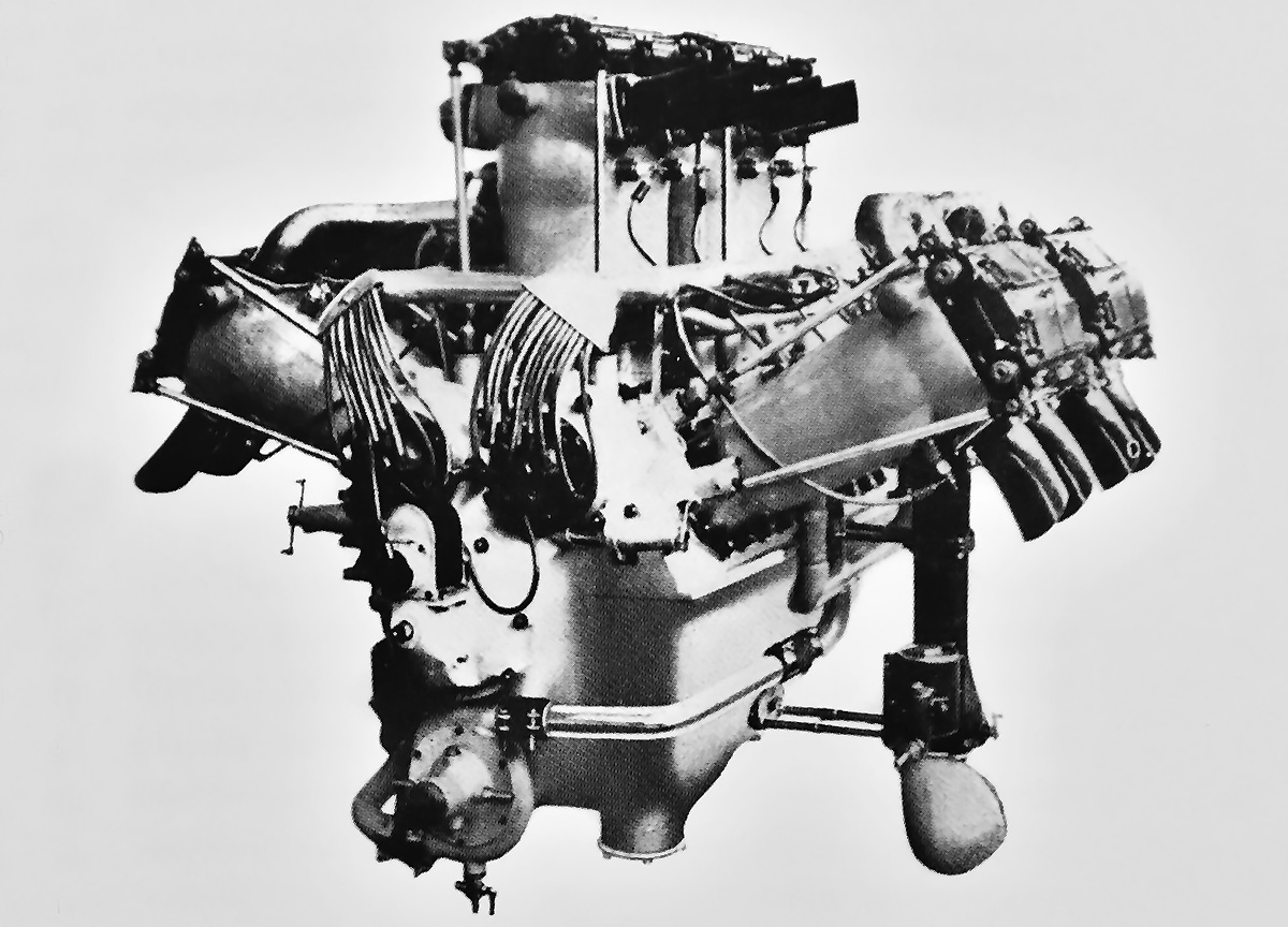
The 18Ga Orion combined the 18-cylinder 18K engine with the modern construction of the 12F-series. Note that the outer cylinder banks have intake and exhaust ports on the same side, while the center cylinder bank has intake and exhaust ports on opposite sides.

The 18Ga Orion had a 4.92 in (125 mm) bore and a 7.09 in (180 mm) stroke. The engine displaced 2,426 cu in (39.8 L) and produced 700 hp (522 kW) at 2,100 rpm and 870 hp (649 kW) at 2,500 rpm. The W-18 engine was 83.1 in (2.11 m) long, 36.6 in (.93 m) wide, and 43.7 in (1.11 m) tall. The engine weighed 1,252 lb (568 kg). The 18Ga completed a 50-hour type test prior to its public debut at the salon de l’Aviation in Paris in November 1930. The engine was used in at least one prototype aircraft, the Amiot 126 bomber. The 18Ga did not enter production, and only around 10 engines were built.

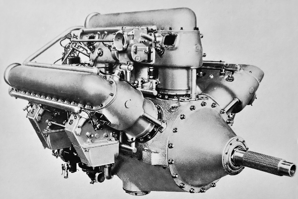
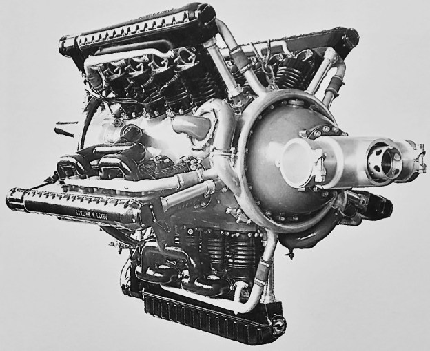
In November 1934, a supercharged version of the 18G Orion was displayed at the salon de l’Aviation in Paris. An updraft carburetor fed the gear-driven, centrifugal supercharger that was mounted to the rear of the engine. Three intake manifolds delivered the air and fuel mixture to the cylinder banks, just like the 12Fb engine. The revised cylinder banks included four valves per cylinder that were actuated by dual overhead camshafts. Each camshaft pair was driven by a vertical shaft at the rear of the engine. The supercharged 18G produced 1,050 hp (783 kW) at 2,150 rpm, but no additional specifications have been found.

A few 12E-series engines are preserved in various museum. No Lorraine F-series, 18-cylinder, or 24-cylinder engines are known to exist.

Lorraine 18G supercharged

The supercharged 18G Orion that was debuted in November 1934. Note the appearance of the new cylinder banks, which included four valves per cylinder.

Sources:
Lorraine-Dietrich by Sébastien Faurès Fustel de Coulanges (2017)
Aerosphere 1939 by Glenn D. Angle (1940)
Les Moteurs a Pistons Aeronautiques Francais Tome I by Alfred Bodemer and Robert Laugier (1987)
Le moteur Lorraine 12 Eb de 450 ch by Gérard Hartmann (undated)
Moteur “Lorraine” 450 C.V. 12 Cylinders en W by Société Lorraine (circa 1925)
Les Moteurs Lorraine by Société Générale Aéronautique (circa 1932)
Moteur “Lorraine” 600 CV (Type 12 Fa.) by Société Lorraine (10 November 1929)

Pratt Whitney R-2060 Yellow Jacket

Pratt & Whitney R-2060 ‘Yellow Jacket’ 20-Cylinder Engine

By William Pearce

Around 1930, the United States Army Air Corps (AAC) was interested in a 1,000 hp (746 kW), liquid-cooled aircraft engine. Somehow, the AAC persuaded Pratt & Whitney (P&W) to develop an experimental engine at its own expense to meet this goal. The engine was the R-2060 Yellow Jacket, and it carried the P&W experimental engine designation X-31. The “Yellow Jacket” name followed the “Wasp” and “Hornet” engine lines from P&W.

Pratt Whitney R-2060 Yellow Jacket

The Pratt & Whitney R-2060 Yellow Jacket was an experimental liquid-cooled engine. Note the annular coolant manifold around the front of the engine that delivered water to the water pumps.

While the R-2060 would be P&W’s first liquid-cooled engine, the company had experimented with liquid-cooled cylinders as early as 1928. In addition, many of P&W’s engineers had experience with liquid-cooled engines while working for other organizations—in particular, those workers who had helped develop liquid-cooled engines at Wright Aeronautical.

The R-2060 had a one-piece, cast aluminum, barrel-type crankcase. Attached radially around the crankcase at 72-degree intervals were five cylinder banks. The lowest (No. 3) cylinder bank was inverted and hung straight down from the crankcase. Each cylinder bank consisted of four individual cylinders arranged in a line. This configuration created a 20-cylinder inline-radial engine. Attached to the front of the crankcase was a propeller gear housing that contained a planetary bevel reduction gear. Mounted to the rear of the crankcase was the supercharger and accessory section.

The crankshaft had four throws and was supported by five main bearings. Mounted to each crankpin was a master connecting rod with four articulated connecting rods—a typical arrangement found in radial engines. Each individual cylinder was surrounded by a steel water jacket. Mounted atop each bank of cylinders was a housing that concealed a single overhead camshaft. The camshaft actuated the one intake valve and one exhaust valve in each cylinder. Each camshaft was driven from the front of the engine by a vertical shaft and bevel gears. Driven from the rear of each camshafts was a magneto that fired the two spark plugs in each cylinder for that cylinder bank. The spark plugs were installed horizontally into the combustion chamber and placed on each exposed side of the cylinder. The camshaft housing on the lower cylinder bank was deeper and served as an oil sump.

Pratt Whitney R-2060 Yellow Jacket right

The 20-cylinder R-2060 was a fairly compact and light engine. Note the camshaft housings atop each cylinder bank and that the housing of the lower bank was deeper to serve as an oil sump. (Tom Fey image via the Aircraft Engine Historical Society)

Air was drawn into the downdraft carburetor mounted at the rear of the engine. Fuel was added, and the mixture then passed into the supercharger, which was primarily used to mix the air and fuel rather than provide boost. The air and fuel flowed from the supercharger through five outlets—one between each cylinder bank. The outlets were cast integral with the crankcase. Attached to each outlet was an intake manifold that branched into two sections, with each section branching further into two additional sections. The four pipes were then connected to the four cylinders of the cylinder bank. The exhaust ports were on the opposite side of the cylinder bank.

Cooling water flowed from the radiator into two inlets on an annular manifold mounted around the rear of the engine. The manifold had five outlets, one for each cylinder bank. Water flowed from the annular manifold into a pipe that ran along each cylinder bank. Branching off from the pipe were connections for each cylinder, with the mounting point near the exhaust port. The water passed by the exhaust port and through the water jacket, exiting near the intake port. The water from each cylinder was collected in another pipe that led to a smaller annular manifold mounted around the front of the engine. Two water pumps driven at the front of the engine took water from the front manifold and returned it to the radiator.

Pratt Whitney R-2060 Yellow Jacket left close

For each cylinder bank, the inlet for the intake manifold was cast into the crankcase. Note the water manifolds attached to the cylinders. The generator can be seen mounted on the left. (Tom Fey image via the Aircraft Engine Historical Society)

The Pratt & Whitney R-2060 Yellow Jacket had a 5.1875 in (132 mm) bore and a 4.875 in (124 mm) stroke. Creating an oversquare (bore larger than the stroke) engine was not typical for P&W and was repeated only with the R-2000, which was derived from the R-1830 with minimal changes. However, the comparatively short stroke helped decrease the engine’s diameter. The R-2060 displaced 2,061 cu in (33.8 L) and was projected to produce 1,500 hp (1,119 kW) at 3,300 rpm. The Yellow Jacket was 68 in (1.73 m) long and 47 in (1.19 m) in diameter. The engine weighed 1,400 lb (635 kg).

Serious design work on the R-2060 was started in March 1931, and single-cylinder testing began in August of the same year. The engine was first run in July 1932, and issues were soon encountered with oil circulation and coolant leaks. Throughout the rest of 1932, P&W worked to solve the oiling issues, control excessive oil consumption, prevent hot spots in various cylinder banks, and eliminate cracks in the cylinder water jackets. On one of its last tests, the R-2060 achieved 1,116 hp (820 kW) at 2,500 rpm, but reaching 1,500 hp (1,119 kW) at 3,300 rpm was beyond what the engine could handle. A major redesign of the engine was needed, and the Yellow Jacket project was subsequently cancelled in early 1933 after accumulating just 46 hours of test running. Only one R-2060 engine was built.

Cancellation of the R-2060 allowed P&W to focus on the development of the air-cooled, two-row, 14-cylinder R-1830 Twin Wasp radial engine. The R-1830 became the most produced aircraft engine of all time, with 173,618 examples built. The sole R-2060 Yellow Jacket was preserved and is part of Pratt & Whitney’s Hangar Museum in East Hartford, Connecticut.

Pratt Whitney R-2060 Yellow Jacket rear

Rear view of the R-2060 illustrates the engine’s carburetor and supercharger housing. The annular manifold around the rear of the engine supplied cooling water to the five cylinder banks. (Kimble D. McCutcheon image via the Aircraft Engine Historical Society)

Sources:
– The Liquid-Cooled Engines of Pratt & Whitney by Kimble D. McCutcheon (presentation at the 2006 Aircraft Engine Historical Society Convention)
Development of Aircraft Engines and Fuels by Robert Schlaifer and S. D. Heron (1950)
The Engines of Pratt & Whitney: A Technical History by Jack Connors (2009)