Monthly Archives: December 2016

big-boy-4002

Union Pacific 4-8-8-4 Big Boy Locomotive

By William Pearce

For some time, locomotives of the Union Pacific Railroad (UP) had struggled to climb the Wasatch mountains between Ogden, Utah and Green River, Wyoming. This 176-mile (283-km) stretch of track started out at 4,300 ft (1,310 m) above sea level in Ogden, climbed the Wasatch Range to 7,300 ft (2,225 m) at the Aspen Tunnel, and then dropped to 6,100 ft (1,859 m) at Green River. Occasionally, up to three helper engines were used to assist heavily loaded trains over the Wasatch mountains.

big-boy-4012

Union Pacific Big Boy 4012 hauling a load of freight through Green River, Wyoming in November 1941. This may have been the recently delivered engine’s first trip west. (Otto Perry image via Denver Public Library)

In 1940, UP was enjoying a period of expansion, and its president, William Jeffers, was interested in a new locomotive that could conquer the Wasatch Range pulling 3,600 tons (3,266 t) unassisted. At the same time, World War II was on the horizon, and the United Sates had begun to increase its production of war material. This put even more traffic on the heavily-traveled Oden-Green River route. Headed by Otto Jabelmann, UP’s Department of Research and Mechanical Standards (DoRMS) in Omaha, Nebraska calculated that 135,000 lbf (600.5 kN) of tractive effort was needed for the engine to achieve its design goal. DoRMS quickly designed the new, massive locomotive and worked closely with the American Locomotive Company (ALCO), the company that agreed to build the engine. The engines were assigned numbers in the 4000-class, and there were plans to name the new series “Wasatch.” However, a worker wrote “Big Boy” in chalk on the front of the first engine while it was being built, and the name stuck. With its tender, the Big Boy was one of the largest and heaviest steam locomotives ever built.

The Big Boy’s design was based closely on the UP’s 4-6-6-4 Challenger that went into service in 1936. However, the Big Boy was larger and heavier than the Challenger and necessitated that UP make many changes to the track between Ogden and Green River. Heavier rail was laid in many places, and curves were realigned and adjusted to maintain a constant curvature. At stations, larger turntables were installed to accommodate the Big Boy’s length. The Big Boy was essentially the largest thing that could normally operate on an existing standard gauge railroad.

big-boy-4002

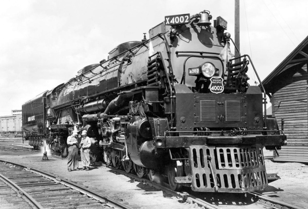
The crew standing next to newly-completed Big Boy 4002 gives scale to every part of the engine: the cylinders, wheels, boiler, etc. The railing on the front of the -1 class engines was originally coolers for the air pump. The -2 class used a standard Wilson aftercooler, as the custom set up on the Class -1 would often crack. As the coolers failed on the -1 class, they were removed and replaced by Wilson units. (Union Pacific image)

The Big Boy utilized a 4-8-8-4 wheel arrangement and was the only locomotive to do so. At the front of the engine was a four-wheel leading truck that had 36 in (.91 m) wheels. This was followed by eight 68 in (1.73 m) drive wheels, with a single piston driving a set of four wheels on each side of the engine. Another set of eight drive wheels followed that were identical to the first. Finally, under the cab was a four-wheel trailing truck with 42 in (1.07 m) wheels. The leading truck and first eight drive wheels were attached to a separate frame than the second set of drive wheels and trailing truck. Between the two sets of drive wheels was a tongue and groove pivot point that allowed the front frame to articulate independently of the rear frame. Mounted to the rear frame was the boiler, firebox, and cab. The articulated locomotive was pioneered by Swiss engineer Anatole Mallet and could handle tighter curves than a standard rigid locomotive. In the case of a long locomotive like the Big Boy, articulation allowed the engine to operate on tracks with curves as sharp as 20 degrees.

ALCO built the Big Boys in Schenectady, New York, and two versions of the engine were made. Starting in 1941, 20 of the 4-8-8-4-1 class engines were made and numbered 4000–4019. In 1944, five of the 4-8-8-4-2 class engines were made and numbered 4020–4024. The difference between the two versions was mainly a different superheater that necessitated changes to the tubing arrangement in the boiler and increased water storage capacity in the tender. These changes were made for maintenance reasons and also due to material shortages during World War II. The first engine, 4000, was delivered to UP in Omaha on 5 September 1941.

big-boy-firebox-and-boiler

The Big Boy’s firebox (left), boiler (middle), and smokebox (right) were all mounted as a single unit and can been seen here, ready to be lowered onto the engine’s frame. The steel that formed the boiler was 1.375 in (35 mm) thick. The two humps above the boiler are the sandboxes. Between the sandboxes is the steam dome, its exposed studs waiting for the cover plate. Exiting the lower part of the smokebox is a duct to feed steam from the superheater to the cylinders. (ALCO image)

All Big Boys were 132 ft 10 in (40.5 m) long and made up of an 85 ft 9.5 in (26.2 m) long engine and a 47 ft .5 in (14.3 m) long tender that carried the locomotive’s coal and water. The locomotive was 16 ft 2.5 in (4.9 m) tall, and its whistle was mounted horizontally so as to not increase the engine’s height. Various ladders and handholds were recessed into the engine and tender to keep the locomotive’s width at a maximum of 11 ft 6 in (3.5 m). The loaded weight of the -1 class was 762,000 lb (345,638 kg) for the engine and 427,500 lb (193,911 kg) for the tender, which gave a total weight of 1,189,500 lb (539,549 kg). The -2 class was heavier at 772,250 lb (350,276 kg) for the engine, 436,500 lb (197,993 kg) for the tender, and a total weight of 1,208,750 lb (548,280 kg). The two sets of eight driving wheels supported 540,000 lb (244,940 kg) on the -1 class and 545,200 lb (247,299 kg) on the -2 class. The maximum weight permitted on each of the engine’s 12 axles was 67,800 lb (30,754 kg).

The centipede-style tender was supported by 14 wheels, each 42 in (1.07 m) tall. The first four wheels made up the leading truck, and the 10 trailing wheels were mounted directly to the tender. The tender originally carried 56,000 lb (25,401 kg) of coal in a front compartment. In the late 1940s, 10 in (254 mm) tall steel sideboards were added to the top of the coal compartment. The sideboards enabled an additional 8,000 lb (3,629 kg) of coal to be loaded, increasing the tender’s capacity to 64,000 lb (29,030 kg). A rear compartment held 24,000 gallons (90,850 L) of water for the -1 class and 25,000 gallons (94,635 L) of water for the -2 class. At full steam, a Big Boy engine would consume the tender’s coal and water supply in two hours, but a proper facility could replenish the coal and water in eight minutes.

big-boy-4023-tender

This image of engine 4023’s tender helps illustrate why the type is known as a centipede tender. Visible on this side are the five wheels mounted to the tender and the two installed in the leading truck. The diagonal row of rivets indicates the partition between the water tank in the rear of the tender and the coal bunker in the front. Note the recessed ladder on the left and the 10 in (254 mm) sideboards atop the tender on the right. (Larry Pieniazek image via Wikimedia Commons)

A large, mechanical stoker auger transported coal from the supply in the tender to the engine’s firebox; no regular fireman could keep up with the Big Boy’s prodigious need for fuel. The firebox was 235 in (5.97 m) long and 96 in (2.44 m) wide and burned coal at around 2,000 °F (1,093 °C). Heat from the firebox flowed through the boiler via a series of tubes, each 22 ft (6.7 m) long. The -1 class engine had 259 tubes: 75 2.25 in (57.2 mm) tubes and 184 4.0 in (101.6 mm) flues. With its altered boiler, the -2 class engine had 285 tubes: 212 2.25 in (57.2 mm) tubes and 73 5.5 in (139.7 mm) flues. If laid end-to-end, the tubes and flues would stretch 5,698 feet (1,737 m) for the -1 class and 6,270 feet (1,911 m) for the -2 class. After passing through the tubes, the soot, embers, smoke, and heat from the burning coal flowed into a smokebox at the front of the engine and then out into the atmosphere via dual stacks. Spent steam from the cylinders was directed through the smokebox and helped create the draft that drew air into the firebox, through the tubes, and out the stacks.

The hot tubes, flues, and firebox provided the surface area to turn water in the boiler to steam. The -1 class had 5,889 sq ft (547.1 sq m) of evaporative surface area, and the -2 class had 5,755 sq ft (534.6 sq m). The water in the boiler was heated until 300 psi (20.7 bar) of steam had been generated. With a temperature of over 420 °F (215 °C), the wet, saturated steam was collected in a steam dome positioned above the boiler. The steam flowed from the dome to the saturated steam chamber in the superheater. Small superheater elements (tubes) took the wet steam back into the flues where it was heated well above its saturation value and converted to dry, superheated steam. The superheater elements delivered the dry steam to the superheated steam chamber in the superheater. Combined, the superheater elements stretched for over a mile (1.6 km). The -1 class had a Type E superheater with a surface area of 2,466 sq ft (299.1 sq m). The -2 class had a Type A superheater with a surface area of 2,043 sq ft (189.8 sq m). The Type A required less maintenance than the Type E and provided more than enough steam for the engine, and this is why the older Type A superheater was used. From the superheater, steam was piped to the Big Boy’s two sets of two cylinders.

big-boy-4014-smokebox

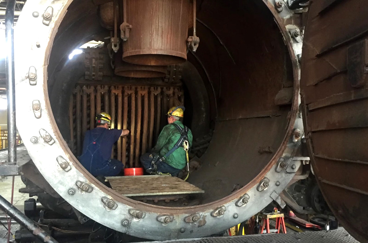
The smokebox of engine 4014 as it undergoes restoration. The workers inside give some perspective to the immense size of the Big Boy. The large vertical ducts are the engine’s dual stacks. The large pipes behind the stacks and leading down the side of the smokebox take steam from the superheater to the cylinders. The vertical tubes are the superheater elements, and just beyond them are the horizontal tubes and flues that extend through the boiler to the firebox. (Union Pacific image via video screenshot)

The Walschaerts valve gear controlled the flow of steam in and out of the cylinders. A piston spool valve mounted in a valve chest above each cylinder slid back and forth. It directed steam from the center of the valve chest to enter one side of the double-acting cylinder while simultaneously opening the other side of the cylinder, expelling the previous steam charge. The steam flowed into the front of the cylinder and filled its 14,176 cu in (232 L) volume, pushing the 23.75 in (603.3 mm) diameter piston back 32 in (812.8 mm) to the rear end of the cylinder. The steam-distribution valve then slid rearward to open the front part of the cylinder, exhausting the spent steam to the smokebox. Simultaneously, fresh steam was directed into the rear part of the cylinder, pushing the piston back to its original position. Although the cylinder was uniform in size, the cylinder’s return volume was only 13,345 cu in (219 L) on account of the 5.75 in (146 mm) diameter, hollow piston rod taking up some room. The piston rod was attached to the connecting rod via a crosshead. The connecting rod extended back to the third driving wheel in the four-wheel set. Here, the connecting rod was attached to the coupling rod, which was connected to all four driving wheels. To aid traction, sand could be deposited on the rails in front of each drive wheel. The Big Boy had two sandboxes mounted on top of the boiler and each held 4,000 lb (1,814 kg) of sand.

The Big Boy was designed for a top speed of 80 mph (129 km/h), but its highest speed reported was a test at 72 mph (116 km/h). It is unlikely the engine was ever operated in service much beyond 50 mph (80 km/h). Of course, hauling the heaviest loads up the steepest grades reduced the engine’s speed to around 12 mph (19 km/h), the speed at which its tractive effort was at a maximum of some 135,375 lbf (602.2 kN). The 80 mph (129 km/h) speed design ensured that parts were built to withstand stresses well beyond what was needed to haul freight at 40 mph (64 km/h).

big-boy-4017-drive-wheels

The front drive wheels on engine 4017. The black box on the right is the cylinder, with the piston rod extending out to the left. A crosshead joins the piston rod with the connecting rod. The connecting rod extends back and attaches to the third drive wheel, and a coupling rod connects all the drive wheels together. (National Railroad Museum image)

At 41 mph (66 km/h), the Big Boy produced some 6,290 hp (4,690 kW) at the drawbar, which would be around 7,157 hp (5,337 kW) produced at the cylinders. Without any slip, each rotation of the drive wheels moved the engine 17.8 ft (5.4 m). At 41 mph (66 km/h), each drive wheel rotated 202 times a minute, and each double-acting piston made 404 strokes. This resulted in roughly 12,869 cu ft (364.4 cu m) of steam passing through the Big Boy’s cylinders every minute.

Four seats were provided in the Big Boy’s cab, although the engine only required a crew of three: an Engineer, a Fireman, and a Brakeman. If needed, the cab could accommodate six occupants with two additional makeshift seats. Each of the 20 -1 class engines cost $265,174 in 1941, and each of the five -2 class engines cost $319,600 in 1944. The equivalent cost for each engine would be over $4,335,000 in 2016.

big-boy-4017

Smoke and steam billow out of Big Boy engine 4017 as it starts off from Rawlins, Wyoming. Even though it is a -1 class, the cooler has been removed from the railing on the front of the engine. (Stan Kistler image)

On engine 4000’s first test run east from Ogden, a train of 3,500 tons (3,175 t) was coupled to the locomotive. This was just below the Big Boy’s rating of 3,600 tons (3,266 t). Although the trip over the Wasatch Range was considered a success, the engine performed slightly below expectations. A quick recheck of the manifest revealed that engine 4000 had actually pulled 3,800 tons (3,447 t)—200 tons (181 t) over its rating. With the true weight realized, the Big Boy’s performance was deemed an unequivocal success.

All Big Boy locomotives were pressed into service as soon as they could be delivered. Originally cleared to pull 3,200 tons (2,903 t) up the 1.14% grade between Ogden and Green River, the engines were eventually allowed to haul 4,450 tons (4,037 t) as experience was gained. On a .82% grade, the engines were cleared to haul 5,360 tons (4,863 t). Theoretically, the Big Boy could pull a train 5.5 miles (8.9 km) long on flat ground from a standing start. In practice, the engine routinely pulled over 100 cars.

During World War II, the Big Boys spent most of their time moving freight between Ogden and Green River. On a typical run from Oden to Evanston, Wyoming, with a stop in Echo, Utah, a Big Boy would take about four hours to cover the 76-mile (122-km), uphill route and climb some 2,500 ft (762 m). Engine 4016 made the trip in 3 hours and 50 minutes while hauling 71 cars, for a weight of 3,883 tons (3,523 t). The Big Boy consumed 74,700 lb (33,883 kg) of coal and 34,800 gallons (131,732 L) of water. This averages to 19,487 lb (8,839 kg) of coal and 9,078 gallons (34,364 L) of water used per hour, or 996 lb of coal and 464 gallons of water per mile (280 kg and 1,089 L per km). Under full steam, the Big Boy was said to consume 22,000 lb (9,979 kg) of coal and 12,000 gallons (45,425 L) of water per hour.

big-boy-4013-and-4004-doubleheading

To expedite service, especially with heavy trains, even the Big Boy used helper engines or was doubleheaded. Here, engines 4013 and 4004 team up to doublehead a train over Sherman Hill on the way from Laramie to Cheyenne in August 1958. (Otto Perry image via Denver Public Library)

After World War II, Big Boys were occasionally used for trips to southern Utah and did make regular trips into Wyoming, going as far as Cheyenne, 483 miles (777 km) from Ogden. The Cheyenne trips required conquering the 1.55% grade up Sherman Hill and passing through the Hermosa Tunnel at around 8,000 ft (2,438 m). In the 1950s, their service expanded on occasion as far east as North Platte, Nebraska and as far south as Denver, Colorado. Although the engines were cleared for other routes, like Ogden to Los Angles, they never made the journey in regular service. The ever-increasing tonnage needing to move on the rails resulted in even the Big Boys using helper engines to speed up travel over the steep mountain passes. Rarely, two Big Boy engines would be linked to doublehead a train quickly over the mountain.

The Big Boy engines proved very reliable in service, but they did require a significant amount of maintenance. UP considered purchasing additional engines, and other railroads thought about buying Big Boys, but resources were somewhat limited during World War II. After the war, diesel locomotives were proving themselves as the prime mover of the future. Still, Big Boys soldiered on and were one of the last steam locomotives in regular service.

big-boy-4021

Well-worn engine 4021 hauls freight through Wyoming in June 1956. The Big Boys were one of the last steam engines in regular service. (Chris Zygmunt Collection image)

The last Big Boy was removed from revenue service on 2 July 1959. The engines were kept in storage until August 1961, when the first were retired. The last Big Boy was retired in July 1962. At the time of their retirement, each of the -1 class Big Boys had accumulated over 1,000,000 miles (1,610,000 km)—the equivalent of traveling from the Earth to the Moon and back twice. Engine 4006 had the most miles, at 1,064,625 (1,713,348 km). Each of the -2 class engines had traveled over 800,000 miles (1,290,000 km)—the equivalent of circling the Earth 32 times. At 855,163 miles (1,376,252 km), engine 4021 had the highest mileage of the -2 class. All total, the Big Boys accumulated 25,008,054 miles (40,246,574 km); this is about the distance from Earth to Venus when the planets are at their closest point.

Although the Big Boy was very impressive, there were other locomotives that were larger, heavier, and more powerful, but probably none that were all three. What makes the Big Boy unique is that even with its massive size and colossal power, it was in regular service for nearly 20 years—it was not an experimental train, and it was not limited to a small section of track. The Big Boy was also not a Mallet-type locomotive. Although it was articulated, the Big Boy was not a compound steam engine, which is the second hallmark of a true Mallet.

Seventeen of the Big Boy engines were scrapped, while the remaining eight were put on display in various museums. As of 2016, seven of the Big Boys are still on display. The remaining engine, 4014, was reacquired by UP in 2013 and underwent a five-year restoration at their facility in Cheyenne, Wyoming. The restoration included converting the engine from coal fired to oil fired and was completed in time for the 150th anniversary celebration of the completion of the transcontinental railroad in Ogden, Utah. In May 2019, Big Boy 4014 once again took to the rails—a living tribute to ALCO, UP, the era of steam, and all the men and women who made it possible. 4014 will be used for special excursion service; its days as a workhorse ended some 50 years ago.

big-boy-4014-boiler-stripped

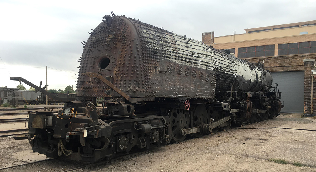
Big Boy 4014 sits in Cheyenne undergoing restoration. The cab has been removed, and the locomotive has been stripped down to the boiler. (Union Pacific image)

Sources:
Big Boy by William W. Kratville (1972)
– “Big Boy: On the Road to Restoration” Trains Magazine Special (2014)
Last of the Giants (Part 1 and Part 2) by Union Pacific
https://www.steamlocomotive.com/locobase.php?country=USA&wheel=4-8-8-4&railroad=up
http://www.steamlocomotive.com/locobase.php?country=USA&wheel=4-8-8-4
http://www.trainorders.com/discussion/read.php?10,2474974
https://www.up.com/aboutup/special_trains/steam/locomotives/4014/about_4014.shtml
https://en.wikipedia.org/wiki/Union_Pacific_Big_Boy
http://www.american-rails.com/big-boy.html
http://www.northeast.railfan.net/bigboy.html
http://www.trainweb.org/brettrw/maps/evanstonsub/evanstonsubmap.html

brayton-1876-inverted-walking-beam-engine

Brayton Ready Motor Hydrocarbon Engine

By William Pearce

With the proliferation of steam power in the late 1800s, many inventors looked to create a simpler and more efficient engine. Rather than having combustion occur outside the engine, as with a steam engine, designers sought to create an internal combustion engine, in which the piston was driven by the expansion of a volatile gas mixture after it was ignited. George Brayton of Boston, Massachusetts was one such inventor, and while his designs would forever influence the internal combustion engine, he never achieved the same level of recognition as many of his contemporaries.

brayton-1872-patent-ready-motor-engine

Patent drawings of George Brayton’s 1872 engine. Gas and air was drawn into cylinder C, compressed by piston D, and stored in reservoir G. The mixture was then released into cylinder A and ignited as it passed through wire gauze e. As the mixture combusted and expanded, it acted on piston B.

Brayton was an inventor, engineer, and machinist who had experience with steam engines. Some of his internal combustion engine experiments date back to the early 1850s, but he began serious development around 1870. In 1872, Brayton patented a new type of engine, the first in a series that became known as the Brayton Ready Motor. The name “Ready Motor” described the fact that the engine was immediately ready for operation, unlike a steam engine. The Brayton engine was also called a “Hydro-Carbon Engine.” The engine used fuel (hydrocarbons) mixed with air as the working fluid that directly acted on the piston, rather than the fuel heating some other working fluid, as with a steam engine. The theoretical process by which the Brayton engine worked became known as the constant-pressure cycle or Brayton cycle. The Brayton cycle in a piston engine involves the pressure in the engine’s cylinder being maintained by the continued combustion of injected fuel as the piston moves down on its power stroke. The constant-pressure Brayton cycle is used in gas turbines and jet engines and is also very similar to the Diesel cycle.

Brayton’s 1872 patent engine was a two-stroke that had two pistons mounted to a common connecting rod. The smaller of the two pistons acted as an air pump, compressing the air to around 65 psi (4.5 bar). A gaseous fuel, such as illuminating gas or carbureted hydrogen, was mixed with the air entering the compression cylinder. Alternatively, an oil fuel, such as naphtha, could be vaporized and added to the air entering the compression cylinder. The air/fuel mixture was then compressed, passed through a valve, and stored in a reservoir. An engine-driven camshaft opened a valve that allowed the pressurized air/fuel mixture to flow from the reservoir and into the large combustion cylinder. Before entering the cylinder, the air/fuel mixture passed through layers of wire gauze where a small pilot flame constantly burned. The pilot flame was kept lit by a continuous, small supply of the air/fuel mixture. As the charge passed through the wire gauze and entered the cylinder, it was ignited by the pilot flame. The combusting and expanding gases created around 45 psi (4.1 bar) of pressure that forced the large piston back in its cylinder, creating the power stroke. At the same time, the small piston was moved toward top dead center in its cylinder, compressing another charge of air for continued operation.

brayton-1874-patent-ready-motor-engine

Brayton’s 1874 patent illustrating a double-sided piston. The upper side of piston B compressed air as the lower side was exposed to the combustion process of air and fuel being mixed and ignited in chamber H. Reservoir C only stored compressed air.

Brayton’s experience with steam engines and how steam expands into the cylinder to smoothly act on the piston probably influenced his desire to have the fuel burn in the cylinder. Gas expansion created by burning fuel acts smoothly on the piston, whereas the sudden ignition of fuel by a spark creates more of an explosion that exposes the piston and other engine components to high stresses. The combustion (motor) cylinder was about twice the volume of the compression (pump) cylinder, and the reservoir was no more than twice the volume of the combustion cylinder. The pressure in the reservoir was always greater than the pressure in the combustion cylinder. A water jacket surrounded the combustion cylinder to provide engine cooling.

While the 1872 patent illustrated an engine utilizing a separate compression piston, Brayton explained in the patent that the same principles of his engine could be applied utilizing both sides of the same piston. One side of the piston would compress the working fluid, while the other side of the piston would be driven by the expanding gases as the working fluid undergoes combustion. The patent drawing also shows a flywheel mounted to the camshaft. Engine power would be distributed from a driving pulley on the opposite end of the flywheel. However, images of early Brayton engines show an articulated rod mounted to the connecting rod that drove the flywheel and drive pulley.

brayton-vertical-ready-motor-engine

Brayton Ready Motor vertical engine with a double-sided piston. The air reservoir was housed in the rocking beam support column. Note the ball governor.

Around 1873, Brayton installed a 4 hp (3.0 kW) engine in a streetcar in Providence, Rhode Island. The streetcar could obtain a speed of 15 mph (24 km/h), but it would barely move with a full load and had difficulty climbing an incline. A larger 12 hp (8.9 kW) engine was substituted, as it was the most powerful Brayton engine that fit in the space available. The engine took up the space of one passenger and enabled the streetcar to climb a 5 percent grade. All total, the streetcar was tested for 18 months. However, the tests indicated issues with wheel slip on the rails, especially in snow or ice, and financial issues brought an end to the experiment.

A drawback to the 1872 engine was the storage of the volatile gas mixture in the reservoir. If any flame were to get past the wire gauze and continue to burn back to the reservoir, the contents of the reservoir would explode. A safety valve prevented damage to the engine, but such an event was very disconcerting to anyone near the engine. The use of light, gaseous fuel exacerbated the issue. In 1874, Brayton switched to a heavy petroleum oil fuel and patented a refined engine in which only air was stored in the reservoir. A small supply of petroleum fuel was pumped into absorbent, porous material contained in a chamber that surrounded the induction pipe. The top of the chamber formed what was basically a burner. As the liquid fuel was heated by the engine and vaporized, it joined with the air charge being admitted into the cylinder via a camshaft-driven valve. The mixture was then ignited as it flowed through the burner section and into the cylinder. The burner stayed lit by residual fuel from the absorbent material mixing with a small amount of air from the reservoir that constantly passed through the burner.

brayton-ready-motor-chart

Engine speed was controlled by an admission valve that regulated the amount of air passing into the cylinder. Although the fuel quantity supplied to the chamber was metered and dependent on engine speed, making changes to engine speed proved to be difficult. Any change in the amount of air supplied meant that there was a brief period of either too much or too little fuel, and this would occasionally extinguish the burner flame. By 1876, this issue had been resolved by implementing a new fuel injection process. The incoming air passed through the absorbent, porous material that was saturated with injected fuel. A jet of air coincided with the injection of fuel and helped distribute the fuel throughout the absorbent material. This injection technique proved more responsive than the earlier vaporization process.

Other changes incorporated in the 1874 engine were the use of both sides of the piston. A rod connected to the compression side of the piston extended out of the engine. The rod decreased the volume of the compression cylinder to less than that of the combustion cylinder. The rod also provided a means to harness power from the reciprocating movement of the piston. Although the rod was mounted on the compression side of the double-sided piston, it was the power stroke of the combustion side that provided the motive force.

brayton-1876-inverted-walking-beam-engine

Circa 1876 Brayton inverted rocking beam engine. The combustion cylinder is on the left, and the smaller compression cylinder is at the center of the engine. Two air reservoirs made up the engine’s base; one was used for operating the engine, and the other was used for starting. The engine is currently in storage at the Smithsonian. (Woody Sins image via John Lucas / smokstak.com)

Development of the Brayton Ready Motor continued, and by 1875, the compression cylinder was completely separate from the combustion cylinder. Both cylinders had the same bore, but the stroke of the compression cylinder was about half that of the combustion cylinder. A number of different engine styles, both vertical and horizontal, were built, and the engines used different ways to harness the power of the compression cylinder. Some engines used the compression cylinder to actuate a rocking beam; other engines had the compression cylinder connected to a crankshaft that turned the power wheel.

By 1875 (and possibly as early as 1873), the Pennsylvania Ready Motor Company in Philadelphia had been established to sell Brayton’s engines, but the engines were built in the Exeter Machine Works in Exeter, New Hampshire. The Brayton Ready Motor may have been the first commercially available internal combustion engine. Engines based on the Brayton cycle were also sold by a number of other companies, including the New York & New Jersey Motor Company (by 1877) and Louis Simon & Sons, in Nottingham, England in 1878.

brayton-1876-vertical-engine

Drawing of the 10 hp (7.5 kW) vertical Brayton Ready Motor displayed at the Centennial Exposition in Philadelphia, Pennsylvania in 1876. This is the same engine that inspired George Selden. The compression cylinder was mounted above the combustion cylinder. The column supporting the rocking beam also contained the reservoir.

In 1878, John Holland used a 4 hp (3.0 kW) vertical Brayton engine in the first submarine powered by an internal combustion engine, the Holland I. While functional, this submarine was not a true success. Holland’s second submarine, the Fenian Ram, used a 15 hp (11.2 kW) horizontal Brayton engine and was launched in 1881. This submarine has been preserved and is displayed in the Paterson Museum in Paterson, New Jersey.

Also in 1878, a vertical engine was tested in an omnibus in Pittsburgh, Pennsylvania, but local authorities would not permit its use to transport passengers. Scottish engine pioneer Dugald Clerk converted a 5 hp (3.7 kW) Brayton engine to spark ignition. This engine was the first two-stroke, spark ignition engine ever built. Horizontal engines were installed in a few boats that operated on the Hudson River. In 1880, the USS Tallapoosa was fitted with a Brayton engine capable of 300 rpm. Other Brayton engines were used for industrial purposes such as powering pumps, cotton gins, or grinding mills. These Brayton engines were the first practical oil engines and were noted for their ease of starting and steady operation.

selden-auto-1906

George Selden and Ernest Samuel Partridge in the Selden automobile in 1905. The vehicle was built in 1903 to prove the viability of Selden’s patent design. Between the front wheels is a three-cylinder Brayton-style engine, which ultimately led to Selden’s patent claims being dismissed.

George Selden was inspired by the 10 hp (7.5 kW) Brayton engine he saw at the 1876 Centennial Exposition in Philadelphia and felt the engine could be adapted to power a practical wheeled vehicle (automobile). In 1879, Selden applied for a patent on his three-cylinder Road Engine, which powered a four-wheel carriage. Selden continued to delay his patent with minor modifications until 1895, when the patent was finally granted despite the fact that Selden had never built the actual vehicle. That did not deter Selden from claiming he invented the automobile and demanding royalties from all automobile manufactures—suing those who refused to pay. Henry Ford led the rebellion against Selden and lost the court case in 1909. However, that ruling was overturned on appeal in 1911. For the successful appeal, Ford demonstrated that Selden’s automobile used an engine based on the Brayton cycle (two-stroke and a constant-pressure cycle), while Ford and others used engines based on the design of Nicolaus Otto (Otto cycle: four-stroke and a constant-volume cycle). No automobiles were built with a Brayton cycle engine; therefore, the automobile manufacturers were not infringing on Selden’s patent.

By the late 1880s, it was becoming clear that the Brayton cycle for piston-driven internal combustion engines was outclassed by the more efficient Otto cycle. The main issue facing the Brayton engine was its relatively low pressure (60–80 psi / 4.1–5.5 bar) combined with excessive friction, pumping, and heat losses between the compression and combustion cylinders.

brayton-horizontal-marine-engine

Horizontal Brayton Ready Motor marine engine that was very similar, but not identical, to the engine used in the Fenian Ram submarine. The combustion cylinder is in the foreground, and the compression cylinder is in the background. The bevel gear powered the propeller shaft.

Brayton continued to develop his engine and applied for a patent in 1887 that outlined a horizontal, fuel injected, four-stroke engine. The cylinder was closed at both its combustion (hot) and non-combustion (cool) sides. Exhaust from the hot side of the cylinder passed through a water-cooled condenser that opened to the cool side of the cylinder. As the piston moved up on the exhaust stroke, the vacuum created in the cool side of the cylinder helped draw exhaust gases out of the hot side of the cylinder. An exhaust valve on the cool side of the cylinder was sprung to open at just above atmospheric pressure. As the piston moved toward the cool side of the cylinder on the intake stroke, the exhaust valve opened to expel the products of combustion. When the intake valve was opened, it brought fresh air into the cylinder and sealed the condenser. The intake valve then closed, and the piston moved toward the hot side of the cylinder to compress the air. Brayton stated in his patent that the cylinder’s cycle provided an abundance of fresh air to increase the engine’s power and efficiency.

Once the air was compressed, fuel was injected into the cylinder. The act of injecting the petroleum oil under pressure converted the fuel to a fine spray that was easily ignitable. The fuel injection pump was controlled by a follower riding on an engine-driven camshaft, and engine speed was controlled by the quantity of fuel injected. Once injected, the fuel was ignited by an incandescent burner made from a coil of platinum wire. This concept is very similar to a hot bulb in a much later semi-diesel engine. Brayton’s fuel injection was ideally suited for the use of heavy fuels. This engine was built with a 7 in (179 mm) bore and a 10 in (254 mm) stroke, displacing 385 cu in (6.31 L). Running at 200 rpm and driving a 30 in (762 mm) fan at 1,500 rpm for 10 hours, the engine only consumed 3.5 gallons (13.2 L) of kerosene.

brayton-1887-patent-ready-motor-engine

Patent drawing showing the cylinder of Brayton’s horizontal, four-stroke engine of 1887. Passage d was used for both intake and exhaust. Passage d1 harnessed the vacuum created under the piston to help draw the exhaust gases out of the cylinder and through the condenser (C). The exhaust was expelled via valve g1. Fresh air was admitted via valve e1, which sealed the condenser. Fuel was injected via “Oil-jet” F and ignited by a platinum coil.

In 1890, Brayton patented his last engine, a vertical four-stroke that featured fuel injection. As the piston moved down on its intake stroke, a valve in the piston head opened and allowed air from the crankcase to enter the vacuum in the cylinder. As the piston moved up on the compression stroke, the exhaust valve opened for a short time to evacuate any remaining products of combustion. With all valves closed, the remaining air was compressed, and fuel was injected in a combustion chamber space above the piston. A connecting rod attached the piston to an inverted rocking beam, and the opposite end of the rocking beam was connected to a crankshaft. A small air pump was driven from a rod connected to the rocking beam. The air pump provided the pressure for the fuel injection system, enabling a blast of air to disperse the fuel into a fine spray as it was forced into the combustion chamber. The fuel was ignited by an incandescent burner and continued to burn as more fuel was injected and the piston moved down on the power stroke. Brayton’s last engine worked through a similar process as the engines Rudolf Diesel began developing in 1893, but Diesel used much higher cylinder pressures.

While traveling in England and still experimenting with engines, Brayton passed in 1892 at the age of 62. Production of his engines had already decreased by the time of his death but may have continued until the early 1900s. While names like Otto and Diesel are known to many today, Brayton’s is relatively unknown despite his pioneering work. Brayton’s engines were used in land vehicles, boats, and submarines before Otto’s or Diesel’s engines successfully ran. Undoubtedly, Brayton’s engineering contributions helped pave the way for many who followed. Out of the hundreds of Brayton Ready Motors that were made, only around six original engines are known to survive today.

brayton-1890-patent-ready-motor-engine

Patent drawing illustrating Brayton’s 1890 inverted rocking beam (D) engine. Air slightly pressurized in the crankcase (A) passed through a valve (b1) in the piston to fill the cylinder (B). Fuel was injected (via g) and ignited by a burner (G) in a combustion chamber space (B1) at the top of the cylinder. A smaller cylinder (J) acted as a pump to power the fuel injector.

Sources:
– Correspondence with John Lucas
– “Improvement in Gas Engines” US patent 125,166 by George B. Brayton (granted 2 April 1872)
– “Gas Engines” US patent 151,468 by George B. Brayton (granted 2 June 1874)
– “Gas and Air Engine” US patent 432,114 by George B. Brayton (applied 15 September 1887)
– “Hydrocarbon Engine” US patent 432,260 by George B. Brayton (granted 15 July 1890)
Internal Fire by C. Lyle Cummins Jr. (1976/1989)
The Gas and Oil Engine by Dugald Clerk (1904)
A Text-Book on Gas, Oil, and Air Engines by Bryan Donkin Jr (1894)
Pioneers, Engineers, and Scoundrels by Beverley Rae Kimes (2005)
– “The Brayton Ready Motor or Hydrocarbon Engine” Scientific American (13 May 1876)
– “Brayton’s Hydrocarbon Engine” Scientific American Supplement, No. 58 (10 February 1877)
– “Selden Patent Not Infringed” The Automobile (12 January 1911)
– “Road Engine” US patent 549,160 by George B Selden (applied 8 May 1879)
– “Events Which Led Up to the Formation of the American Street Railway Association” by D. F. Longstreet The Street Railway Journal (November 1892)
http://todayinsci.com/B/Brayton_George/BraytonGeorgeBoat.htm
http://todayinsci.com/B/Brayton_George/BraytonGeorgeEngine.htm
http://todayinsci.com/B/Brayton_George/BraytonGeorgeEngine2.htm
http://todayinsci.com/B/Brayton_George/BraytonGeorge.htm
https://www.smokstak.com/forum/showthread.php?t=115633
http://users.zoominternet.net/~pcgray/FenianRam/fenianarticle.htm
http://vintagemachinery.org/mfgindex/imagedetail.aspx?id=6367