Category Archives: Stationary Engines

Napier-Deltic-T18-37K-Marine-Engine

Napier Deltic Opposed-Piston Diesel Engine

By William Pearce

In 1933, the British engineering firm D. Napier & Son (Napier) acquired licenses to produce the Junkers Jumo 204 and 205 aircraft engines. Napier sought to diversify and expand its aircraft engine business, and the company felt the two-stroke, opposed-piston, diesel engines would usher in an era of safe and fuel-efficient air travel. Napier made some modifications to the Jumo engines, but the internal components were mostly unchanged. The Jumo 204 was built as the Napier Culverin (E102), and the Jumo 205 was planned as the Napier Cutlass (E103). The Culverin was first run on 24 September 1934, but the engine garnered little interest and no orders. By 1936, after only seven Culverins were made and no Cutlasses, Napier halted further work on opposed-piston diesel aircraft engines. English Electric took over Napier in November 1942.
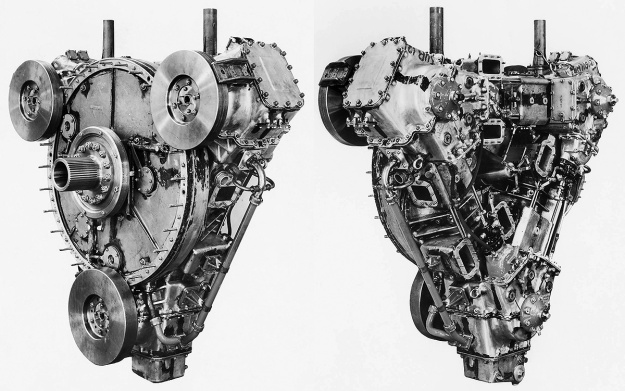
Napier-Deltic-E130-Three-cylinder-test-engine

The Napier E130 three-cylinder test engine that validated the triangular engine arrangement. Each of the engine’s crankshafts had a flywheel on the drive end (left). The six intake chamber openings are visible on the free (non-drive) end (right). Note the vertical coolant pipes on top of the engine. (Napier/NPHT/IMechE images)

In 1944, the British Admiralty desired to increase the survivability of the Motor Torpedo Boat (MTB). One of the main issues was that MTBs used gasoline engines. Gasoline liquid is highly flammable, and gasoline vapor is highly explosive. MTB safety would be improved if a switch to diesel engines could be made. Diesel fuel has non-explosive characteristics and a much higher flashpoint than gasoline. However, at the time, there were no suitable diesel engines to power MTBs.

Around 1945, Napier and other companies submitted proposals to the Admiralty for a light-weight, powerful, and compact 18-cylinder diesel engine. Napier’s new engine carried the company designation E130, and the design was influenced by their experience with the Junkers Jumo diesel engines, their work on the Culverin and Cutlass, and analyses of other Jumo six-cylinder engines captured during World War II. However, there is no mention of the Junkers Jumo 223 contributing to Napier’s engine design. In early 1946, the Admiralty selected the Napier design and issued a developmental contract that covered the construction of one single-cylinder test engine, one three-cylinder test engine, and six prototype 18-cylinder engines.
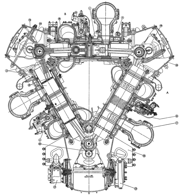
Napier-Deltic-drive-end-section

Section drawing from the drive end of a Deltic engine. The air chamber surrounds the intake end of the cylinder, and the exhaust manifolds are mounted to the outer sides of the engine. Note the rotation of the crankshafts. (Napier/NPHT/IMechE image)

Napier’s liquid-cooled, two-stroke engine used opposed-pistons, a design feature that eliminated many parts, required no cylinder head, improved thermal efficiency, and resulted in more power for a given size and weight. In an opposed-piston engine, each cylinder has two pistons that move toward each other to form a single combustion space near the center of the cylinder. Ports in the cylinder wall that are covered and uncovered by the pistons bring in air and allow exhaust gases to escape. The most unusual aspect of Napier’s design was that the engine was formed as an inverted triangle, with a crankshaft at each corner. Because of its triangular structure, the name Deltic was selected in reference to the Greek letter Delta, and the 18-cylinder engine was known as the Deltic D18 (or just 18). The triangular design resulted in a compact engine with a very rigid structure.

Design work on the Napier Deltic started under Ben Barlow, George Murray, and Ernest Chatterton, Chief Engineer of the Piston Engine Division at Napier. The project was initially overseen by Henry Nelson, with Herbert Sammons taking over in 1949. The Deltic engine formed an equilateral triangle with each of its three cylinder banks angled at 60 degrees. Cast aluminum crankcase housings were at each corner of the triangle, with the lower crankcase incorporating an oil sump and also serving as the engine’s base. Each cast aluminum cylinder bank was sandwiched between two crankcases via through bolts. The monobloc cylinder banks were identical, as were the upper two crankcases. However, various ancillary components were installed according to the casting’s position on the complete engine.
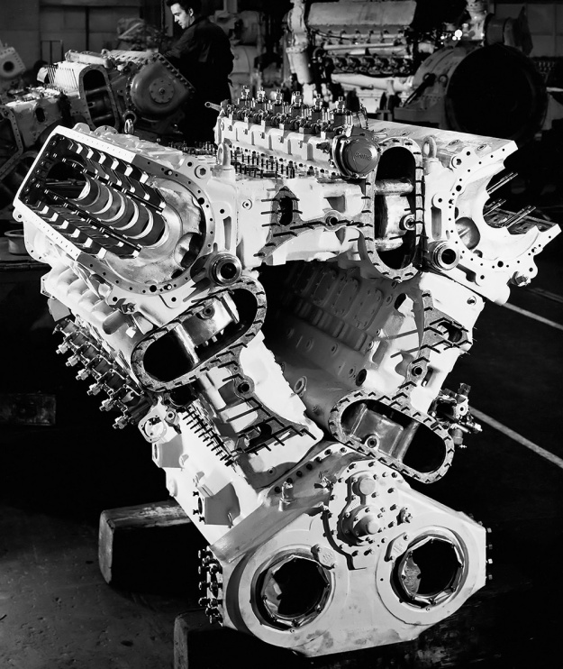
Napier-Deltic-18-Triangle-Case

The assembled cylinder banks and crankcases of an 18-cylinder Napier Deltic engine seen from the free end. Note the open space between the cylinder banks. The stadium (oval) ports are to the air chambers. The bushings visible in the upper crankcases, at the triangle’s corners, supported the shafts that drove the blower. (Napier/NPHT/IMechE image)

The forged-steel cylinder wet liners were open-ended and had a chrome-plated bore to reduce wear. Part of the bore was etched with small dimples to retain lubricating oil and reduce piston ring wear. The liner was approximately 32 in (813 mm) long and protruded some distance into the crankcases. The ends of the liner were notched to allow clearance for the swinging connecting rods. Near one end of the liner were 14 intake ports with a tangential entry to impart a swirling motion of the incoming air. The swirling air helped scavenge the cylinder through the nine exhaust ports near the other end of the liner. In each cylinder, one piston would cover and uncover the intake ports while the other piston would do the same for the exhaust ports. The exhaust ports were uncovered (opened) 34.5 degrees before the intake ports. Both sets of ports were uncovered (open) for 101.5 degrees, and the intake ports were uncovered (open) for 5.5 degrees after the exhaust ports were covered (closed). The placement of the intake and exhaust ports at opposite ends of the cylinder liner allowed for uniflow scavenging of the cylinder. The liners were shrink-fitted into the cylinder banks and secured by an annular nut on the intake side.

The two-piece pistons consisted of a cast aluminum outer body and a forged Y-alloy (nickel-aluminum alloy) inner member that held the wrist pin. The inner member was heat-shrunk to the outer piston body and secured by a large circlip. Oil flowed between the two pieces to cool the piston. Three compression rings were positioned just below the piston crown, and two oil scraper rings were located near the bottom of the piston skirt. The pistons were attached to fork-and-blade connecting rods, with the exhaust pistons mounted to the forked rods and the intake pistons mounted to the blade rods. The opposed pistons created a compression ratio of 17.5 to 1 (some sources say 15 to 1).
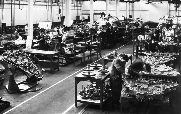
Napier-Deltic-assembly

Napier Deltic engine assembly, with phasing gear housings being built up in the lower right. At left is a completed phasing gear housing; note the two idler gears connecting the lower crankshaft to the central output shaft. Toward the center are Deltics in various stages of assembly. A completed engine without its blower installed is in the upper right. Note the opening in the center of the engine. (Napier/NPHT/IMechE image)

A two-piece phasing gear housing at the drive end of the engine contained the gears that connected the crankshafts to the main output shaft. The main output shaft was usually located at the center of the engine, but different phasing gear housings allowed for different output shaft locations. Each crankshaft was coupled to its drive gear via a short, flexible quill shaft. When viewed from the free (non-drive) end of the engine, the upper two crankshafts rotated clockwise and were connected to the main output shaft via one idler gear. The lower crankshaft rotated counterclockwise and was connected to the main output shaft via two idler gears. The idler gears could be repositioned to reverse the rotation of the output shaft. Each crankshaft was supported in its crankcase by seven main bearings, and each main bearing cap was secured by four studs and two transverse bolts. The crankshafts were phased so that the exhaust piston in each cylinder led the intake piston by 20 degrees. The reverse rotation of the lower crankshaft, and the crankshaft phasing was devised by Herbert Penwarden from the Admiralty Engineering Laboratory.

Via a quill shaft and bevel gears, each crankshaft also drove a camshaft for the fuel injection pumps. The camshaft was located in a housing bolted to the outer side of each cylinder bank, near its center. Each camshaft operated six fuel injection pumps, and each pump fed fuel to two injectors per cylinder. The timing of the pumps changed depending on engine RPM. The upper two crankshafts drove separate flexible drive shafts for the blower (weak supercharger). The driveshafts were positioned at the upper, inner corners of the engine triangle. They led to the opposite end of the engine and powered a single-stage, double-sided centrifugal blower. The impeller was 15.5 in (394 mm) in diameter and rotated at 5.72 times crankshaft speed, creating 7.8 psi of boost (.53 bar). The pressurized air from the blower was fed into a chamber that extended through each cylinder bank and that surrounded the intake ports in the cylinder liner. Exhaust gases were collected via a water-cooled manifold that attached to the outer side of each cylinder bank. The lower crankshaft drove a flexible drive shaft to power the engine’s two oil and two water pumps.

Napier-Deltic-T18-37K-sections-display

Basic sections of the Deltic (T18-37K) marine engine. From left to right are the blower section (turbo-blower in this case), D18-cylinder engine section, phasing gear housing, and the bi-directional gearbox. The Deltic was a powerful diesel engine for its size and weight. (Napier/NPHT/IMechE image)

When viewing the engine from the free end, the cylinder banks were designated as follows: left was Bank A; upper, horizontal was Bank B; and right was Bank C. The crankshafts were designated as follows: upper left was Crankshaft AB, upper right was Crankshaft BC, and lower was Crankshaft CA. The cylinder rows were numbered with Bank 1 at the free end, and subsequent banks were numbered consecutively with Bank 6 at the drive end. The Deltic D18’s firing order was Bank C cylinder 1 (C1), A6, B1, C5, A1, B5, C3, A5, B3, C4, A3, B4, C2, A4, B2, C6, A2, and B6.

The Napier Deltic had a 5.125 in (130 mm) bore and a 7.25 in (184 mm) stroke (x2). This gave each cylinder a displacement of 299 cu in (4.9 L), and the 18-cylinder engine displaced 5,384 cu in (88.2 L). The bare engine (without the bi-directional marine gearbox) had a maximum, 15-minute output of 2,730 hp (2,036 kW) at 2,000 rpm with a specific fuel consumption (sfc) of .380 lb/hp/hr (231 g/kW/h). The Deltic’s continuous rating was 2,035 hp (1,517 kW) at 1,700 rpm with a sfc of .364 lb/hp/hr (221 g/kW/h). With the bi-directional gearbox, the engine produced 2,500 hp (1,864 kW) at 2,000 rpm with a sfc of .415 lb/hp/hr (252 g/kW/h) and 1,875 hp (1,398 kW) at 1,700 rpm with a sfc of .395 lb/hp/hr (240 g/kW/h). The Deltic D18 was 105 in (2.67 m) long, 71.25 in (1.81 m) wide, and 80 in (2.03 m) tall. The bi-directional gearbox added another 36 in (.91 m). The engine weighed 8,860 lb (4,018 kg) without the bi-directional gearbox and 10,500 lb (4,763 kg) with it.

The single-cylinder test engine was designed from October to December 1946, with the three-cylinder engine following from January to May 1947. Testing of these engines started as soon as construction was completed. The three-cylinder engine represented just one row of a Deltic engine, but it demonstrated the validity of the components used in the triangular arrangement.
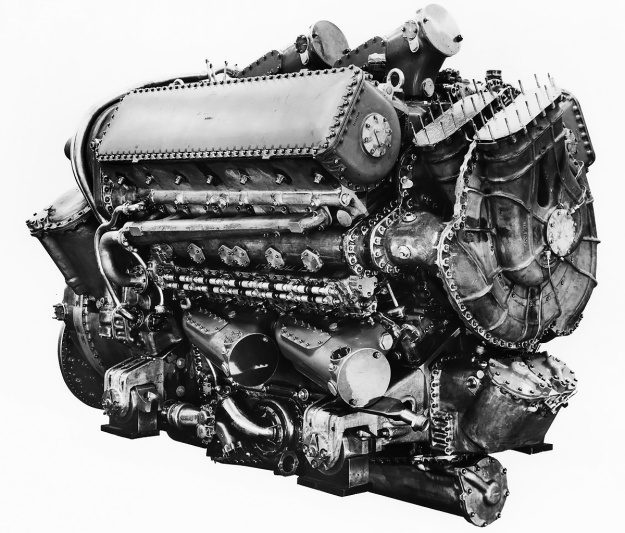
Napier-Deltic-D18-E130-Prototype

Free end of the 2,500 hp (1,864 kW) Deltic D18-1 (E130) prototype engine. Note the two intakes, one for each side of the double-sided blower. Each cylinder bank had two, large exhaust manifolds. The transverse bolts threaded into the main bearings can be seen on the side of the upper crankcase. (Napier/NPHT/IMechE image)

The first 18-cylinder Deltic Series I engine was assembled by March 1950. The engine was soon to be tested at Napier’s works in Acton, England; however, a cable broke as the engine was being mounted to the stand. It fell on the stand, damaging the engine and the test stand. Repairs were made, and engine began testing in April 1950. The 18-cylinder Deltic fired a cylinder every 20 degrees of crankshaft rotation, which resulted in smooth, nearly-constant output torque. Engine idle was around 600 rpm, and the Deltic demonstrated a gross mechanical efficiency of 85.5% at 2,000 rpm. In late 1951, two Deltics were installed in place of the three Mercedes-Benz MB 501 V-20 engines in a former German E-boat S-212 (redesignated Fast Patrol Boat P5212). By January 1952, the originally-contracted six Deltic D18 engines had been built. In 1953, an Admiralty 1,000-hr type test was completed and indicated the engine could run 2,000 hours between overhauls.

By 1954, Napier was offering a commercial version of the Deltic D18 Series I (E169). This was basically a de-rated engine. The commercial engine produced 1,900 hp (1,417 kW) at 1,500 rpm with a sfc of .363 lb/hp/hr (221 g/kW/h) and could operate for 5,000 hours between overhauls. In addition to a variety of marine applications, Deltic engines could also run power generation sets, water pumps, and be used to power traction motors for locomotives. Napier also built a nine-cylinder version with three banks of three cylinders. The Deltic 9 (E159/E165) displaced 2,692 cu in (44.1 L) and had a one-sided centrifugal blower but was otherwise of the same construction as the Deltic D18. It fired one cylinder for every 40 degrees of crankshaft rotation. Maximum output for the Deltic 9 was 1,250 hp (932 kW) at 2,000 rpm for the high-power version and 950 hp (708 kW) at 1,500 rpm for the commercial version. By late 1955, Deltic test and production engines had accumulated over 20,000 hours of operation.
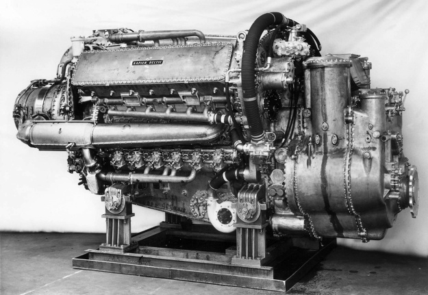
Napier-Deltic-C18-5-Compound-Marine-Engine

The 5,500 hp (4,101 kW) compound Deltic C18 (E185) engine was the most powerful piston engine Napier ever built. Although it is covered, the intake can be seen in the upper part of the phasing gear housing. Exhaust was routed through the three-stage turbine, which powered the eight-stage compressor inside the engine’s triangle. (Napier/NPHT/IMechE image)

In 1956, Napier built a compound diesel engine known as the Deltic C18 (E185). Serious development of the C18 occurred after the Napier Nomad II compound diesel aircraft engine was cancelled in 1955. The Deltic C18 had an eight-stage (some sources say 12-stage, which was the same number of stages as used in the Nomad II) axial compressor positioned inside the engine triangle. The compressor was driven by a three-stage turbine, which was powered by the engine’s exhaust gases. The turbine was positioned in the normal blower position on the free end of the engine. A new phasing gear housing was constructed with an opening that allowed air into the center of the engine triangle and served as the inlet for the compressor. The Deltic C18 produced 5,500 hp (4,101 kW) at 2,000 rpm. The engine was 124 in (3.15 m) long, 65 in (1.65 m) wide, and 77 in (1.96 m) tall. The C18 weighed approximately 10,700 lb (4,853 kg). The engine was tested in 1957, but only one experimental C18 was built. While undergoing power tests, the engine was intentionally pushed beyond its limits until a connecting rod failed at 5,600 hp (4,176 kW). The rod came through the crankcase, but the damage was never repaired due to the Navy’s increased focus on gas turbine engines.

By 1956, Napier had introduced some minor changes as the Series II Deltic engines, but one major change was the addition of a turbo-blower. These engines were known as turbo-blown, and they were designated as the Deltic T18 (E171/E239). Exhaust gases were collected and fed into an axial-flow turbine mounted behind the blower. The turbine wheel was 18.04 in (458 mm) in diameter and helped turn the blower via a geared shaft. The turbine wheel turned at .756 times the speed of the blower impeller. The blower was still driven by the upper crankshafts, but it now turned at 8.266 times crankshaft speed. The turbo-blower created 19 psi (1.31 bar) of boost. The piston was redesigned and consisted of three-pieces: a Hidural 5 (copper alloy) crown that screwed onto an aluminum skirt to form the outer body, and a Y-alloy (nickel-aluminum alloy) inner member that held the wrist pin. A third scraper ring was added to the piston skirt. The compression ratio was increased to 17.9 to 1, and the engine used one fuel injector per cylinder. The Deltic T18 had an output of 3,100 hp (2,312 kW) at 2,100 rpm and 2,400 hp (1,641 kW) at 1,800 rpm. SFC was .414 lb/hp/hr (252 g/kW/h) and .404 lb/hp/hr (246 g/kW/h) respectively. The engine was 118 in (3.00 m) long, 75 in (1.91 m) wide, and 84 in (2.13 m) tall. The T18 weighed around 13,630 lb (6,183 kg) with the bi-directional gearbox and 11,050 lb (5,012 kg) without it. The turbo-blown nine-cylinder Deltic T9 (E172/E198) produced 1,100 hp (820 kW) at 1,600 rpm.

Napier-Deltic-T18-37K-Marine-Engine

The 3,100 hp (2,312 kW) turbo-blown Deltic T18-37K (E239) engine was most widely used in Motor Torpedo Boats. Note the exhaust manifolds leading to the turbine with its large intake at the rear of the engine. The short duct connecting the blower to the upper cylinder bank is visible. (Napier/NPHT/IMechE image)

More changes were incorporated into the Series III engines, which also introduced charge-cooling with the Deltic CT18 (E263) in 1966. For the CT18, a single drive shaft passed through the center of the engine to deliver power from the phasing gear housing to the turbo-blower. The shaft turned at 5.16 times crankshaft speed, and both the blower impeller and turbine wheel were mounted to the drive shaft. The single-sided blower impeller was relocated to behind the turbine wheel. A water-filled aftercooler was mounted before each opening of the engine’s three air compartments. The aftercooler dropped the charge temperature from 259° F (126° C) to 144° F (62°C). Pistons were again redesigned, with the Hidural 5 (copper alloy) crown bolting to the aluminum skirt. For the Deltic CT18, power increased to 3,700 hp (2,759 kw) at 2,100 rpm with a sfc of .403 lb/hp/hr (245 g/kW/h) and 2,750 hp (2,051 kW) at 1,800 rpm with a sfc of .395 lb/hp/hr (240 g/kW/h). By 1968, further development had increased the output to 4,000 hp (2,983 kW) at 2,100 rpm with a sfc of .401 lb/hp/hr (244 g/kW/h) and 3,000 hp (2,237 kW) at 1,800 rpm with a sfc of .399 lb/hp/hr (243 g/kW/h). The CT18 weighed 15,382 lb (6,977 kg) with its bi-directional gearbox.

As Napier declined in the late 1960s, English Electric moved Deltic production to the newly acquired Paxman Engine Division. The General Electric Company (GEC, not related to the US company General Electric / GE) purchased English Electric in 1968. What was once Napier basically closed in 1969. In 1975, GEC reformed Paxman Engine Division as Paxman Diesels Limited. Paxman continued to support Deltic engines, developing the CT18 to 4,140 hp (3,087 kW) in 1978 and reworking the mechanically-blown Deltic 9 for production as the D9-59K (E280) in the early 1980s. The D9-59K was constructed almost entirely with non-ferrous (non-magnetic) parts for mine-sweeper duties. In 2000, MAN acquired what used to be Paxman, and Rolls-Royce was awarded a contract to support Deltic engines in 2001. The contract was carried through until 2012, but it is not clear if the contract was extended beyond that year.
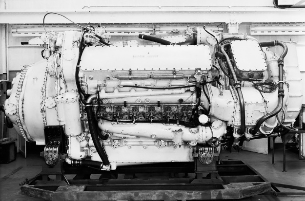
Napier-Deltic-CT18-42K-Charge-Cooled-engine

A 3,700 hp (2,759 kw) charge-cooled and turbo-blown Deltic CT18-42K (E263) engine. The turbine is located between the engine and the blower. Note the large, square aftercooler in the air duct between the blower and the engine. (Napier/NPHT/IMechE image)

Deltic engines powered a number of various MTBs, including the Royal Navy’s Dark-class (18 produced). Two 3,100 hp (2,312 kW) Deltic C18 turbo-blown engines powered each Nasty-class / Tjeld-class fast patrol boat (total of 49 built), which were designed in 1959 and put in service in 1960. These boats served with the navies of Norway, the United States, Greece, Germany, and Turkey. The boats had a top speed of 52 mph (83 km/h), and some were in service until the 1990s. Deltic engines powered Ton-class minesweepers (over 100 built) as well as the pulse generators for other minesweepers. Deltics were still being installed in new military boats during the 1980s, with the 1,180 hp (880 kW) Deltic T9-powered Hunt-class minesweepers (13 built) still in service. A few commercial vessels were also powered by Deltic engines—the largest installation was four 1,850 hp (1,380 kW) engines for the 513.5-ft (156.5-m) ore carrier Bahama King in 1958.

In 1955, two 1,650 hp (1,230 kW) Deltic D18-12 (E158) engines were used in the English Electric DP1, a prototype diesel-electric locomotive. The engines powered six English Electric EE829-1A traction motors that gave the locomotive 50,000 lbf (222.4 kN) of tractive effort. The DP1 proved successful, resulting in 22 British Rail Class 55 locomotives powered by Deltic D18-25 (E169) engines being built in the early 1960s. Called Deltics, these locomotives could exceed 110 mph (177 km/h) and were in service until the early 1980s. One 1,100 hp (919 kW) Deltic T9-29 (E172) engine was used in each of the smaller British Rail Class 23 locomotives, known as Baby Deltics. The engine powered four English Electric traction motors that gave the locomotive 47,000 lbf (209.1 kN) of tractive effort. The Baby Deltics entered service in 1959, but they were not as successful as their bigger counterparts due to shorter runs and frequent stops. All Baby Deltics were withdrawn from service by 1971.
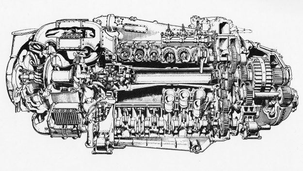
Napier-Deltic-CT18-Charge-Cooled-cutaway

Cutaway view of a Deltic CT-18 charge-cooled and turbo-blown engine. Note the shaft through the center of the engine that powered the turbo-blower from the phasing gear. (Napier/NPHT/IMechE image)

Other Deltic designs included a 735 hp (548 kW) inline six-cylinder (E164/E197) with one bank of six cylinders and a 1,420 hp (1,059 kW) 15-cylinder (E162) with three banks of five cylinders, but these engines were not built. A 24-cylinder square engine (E260) with four crankshafts and four banks of six cylinders was also designed for an output of 5,400 hp (4,027 kW). The square engine design had much more in common with the Deltic than the Jumo 223, but it was not constructed. Including the nine-cylinder version, over 600 Deltic engines were made. A number of Deltic engines survive. Some are still operational in preserved boats or locomotives, allowing the unusual roar of the triangular two-stroke Deltic to still be heard. Others engines are in various museums, and a few are privately owned.

Note: In some cases, the Napier E number is one example of the type, with additional E numbers existing for similar engines with different configurations (marine vs rail applications). Around 100 E numbers were assigned to various Deltic designs.
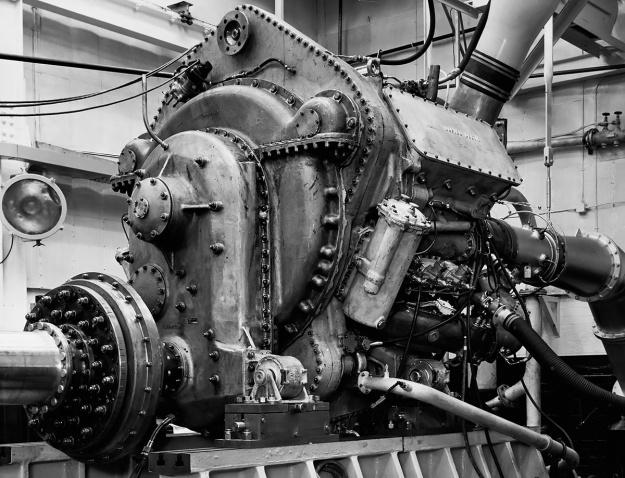
Napier-Deltic-T9-33-Locomotive-Rraction-Engine

A 1,250 hp (932 kW) turbo-blown nine-cylinder Deltic T9-33 (E198) under test at Napier’s factory in Acton. The engine was similar to those used in the Baby Deltic Locomotives. Note the low position of the output shaft. (Napier/NPHT/IMechE image)

Sources:
– “The Napier Deltic Diesel Engine” by Ernest Chatterton, SAE Transactions Vol 64 (1956)
Opposed Piston Engines by Jean-Pierre Pirault and Martin Flint (2010)
Course Notes on the Deltic Engine Type T18-37K by D. Napier & Son Ltd. (December 1967)
– “Development of the Napier Deltic Charge Cooled Engine” by R. P. Taylor and C. H. Davison, Proceedings of the Institution of Mechanical Engineers Vol 183 (1968–69)
By Precision Into Power by Alan Vessey (2007)
Napier Powered by Alan Vessey (1997)
https://www.ptfnasty.com/ptfDeltic.html
http://www.npht.org/deltic/4579702653
Otto-Langen Atmospheric Engine

Otto-Langen Atmospheric Engine

By William Pearce

Before devoting his life to engine development, Nicolaus Otto worked selling merchandise to grocery stores around Cologne, Germany, but he always had an interest in science and technology. Otto became entirely focused on internal combustion engines around 1860, after reading about Étienne Lenoir’s engine. He was so fascinated that he had an example built for experimentation in 1861.

Otto-Langen 1866 drawing

Drawing of the Otto-Langen engine circa 1866. Note the piston (K) and its rack (X) in the cylinder (A). The drawing also shows an early version of the over-running clutch (S).

Otto tried a wide-range of modifications to the Lenoir atmospheric engine in search of better performance. One interesting finding was that when the engine’s cylinder and piston were used to compress the incoming air and fuel charge, the resulting power stroke had enough energy to rotate the crankshaft through several revolutions. While Otto had discovered a number of improvements for the Lenoir atmospheric engine, creating a compression engine was a bit beyond the contemporary technology. Otto had already spent his saving and what he had borrowed from friends. To continue his research and develop an atmospheric engine, he needed money.

For some time, Eugen Langen ran his family’s sugar refining business in Cologne, Germany, but, like Nicolaus Otto, his true passion was for science and technology. Langen had become a fairly wealthy man from the family business and from a few of his own ventures. In 1863, his business was running smoothly, and he was looking for a new enterprise. Langen had read of the Lenoir engine and contemplated how such a device could benefit industry.

Otto-Langen repro overrunning clutch

A reproduction of the over-running clutch built by Wayne Grenning of Grenning Models. Counterclockwise movement of the gear brings the shoes to their stops and allows the gear to rotate free from the inner hub. When the gear rotates clockwise, the shoes slide on their rollers until they are wedged between the gear and the inner hub, locking the two together. The clutch was originally designed by Franz Reuleaux, and later clutches used on the Otto-Langen had three shoes. (Wayne Grenning image)

Exactly how Otto and Langen met is not known. Perhaps Otto sought out Langen as a financial backer, or perhaps they met through a third party. Regardless, Langen witnessed Otto’s unrefined atmospheric engine running on 9 February 1864. Langen saw potential in the engine and its inventor. Langen and Otto formed N.A. Otto & Cie on 31 March 1864 to develop and manufacture internal combustion engines.

Otto-Langen repro piston rack

Other reproduction parts built by Wayne Grenning. The piston with its rack attached are shown outside of the cylinder housing column. The piston and rack weigh around 80 lb (36 kg). The studs seen at the base of the column are where the slide valve mounts. (Wayne Grenning image)

Three years of experimentation and refinement occurred before N.A. Otto & Cie had a marketable engine that was superior to the competition. The Otto-Langen .5 hp (.37 kW), single-cylinder, atmospheric engine made its public debut at the 1867 International Exposition in Paris, France (Exposition universelle de 1867). Nothing about the engine appeared remarkable, but interest piqued when a demonstration showed that the engine consumed half the gas of other engines of the same power. The engine’s remarkably efficient performance won it the grand prize.

The Otto-Langen engine consisted of a vertical column that formed a single cylinder. A free piston was installed in the cylinder, with the piston head facing down. Attached to the upper part of the piston was a rack gear that extended out vertically above the engine. The rack engaged the one-way, over-running (sprag) clutch that was mounted on the engine’s main drive shaft. The clutch was the first of its type and was designed by Franz Reuleaux. The flywheel was mounted on one side of the main drive shaft, and the belt drive pulley was mounted on the other side. On the flywheel side of the main drive shaft was the main drive gear. The main gear engaged an accessory gear, which drove the accessory shaft. Typically, the accessory gear was larger and had more teeth than the main gear. The difference resulted in an accessory gear speed slower than that of the main gear, which helped reduce impact forces on the accessory gear drive.

Otto-Langen Rough Tumble Engineers top

Top view of the Otto-Langen engine at the Rough and Tumble Engineers Historical Association in Kinzers, Pennsylvania. It is the oldest internal combustion engine in the Americas. Installed on the main drive shaft (top) from left to right are the flywheel, main drive gear, over-running clutch, and belt drive. Installed on the accessory shaft (bottom) from left to right are the accessory drive gear, secondary eccentric, main eccentric, and ratcheting gear. (Rough and Tumble Engineers image)

The accessory gear was mounted on and drove the accessory shaft. Also on the accessory shaft were two eccentrics and a ratcheting gear. The ratcheting gear was attached directly to and turned with the accessory shaft. The two eccentrics operated independently of the accessory shaft and were mostly stationary. A pawl would engage the ratcheting gear and drive the main eccentric. This eccentric lifted the piston and rack assembly and also drove the second eccentric, which operated the hand-scraped slide valve at the base of the engine via a control rod. When the eccentrics raised the piston and slide valve, the air and fuel mixture was draw into the cylinder. The slide valve then aligned to a port with an internal flame that ignited the gaseous mixture in the cylinder.

On the power stroke, the free piston had unrestricted upward movement in the cylinder and took advantage of the complete expansion of gases during the combustion process. As the piston moved up, the rack attached to the upper side of the piston moved freely on the clutch. As atmospheric pressure and gravity pulled the rack and piston back down, the rack engaged the over-running clutch that drove the main drive shaft. A flyball governor was driven by the accessory shaft and controlled an exhaust valve. With a closed exhaust valve, the piston could not fully descend. As the speed of the accessory shaft decreased below the desired rpm, the governor opened the exhaust valve, which allowed the piston to descend. This movement of the piston and its attached rack assembly tripped an arm that engaged the pawl to the ratcheting gear, driving the eccentrics and subsequently firing the engine.

Otto-Langen reproduction pawl

Grenning’s full-size reproduction of a .5 hp (.37 kW) Otto-Langen engine under power. The accessory shaft is in the foreground, and the pawl in the center of the image is about to engage the ratcheting gear. The ratcheting gear will then drive the eccentrics. (Wayne Grenning image)

The internal flame that ignited the gaseous mixture in the cylinder was extinguished on each power stroke. The internal flame was relit by an external flame via a port on the slide valve that aligned as the valve moved. The Otto-Langen engine was run on illuminating gas, which was typically distributed at around .07 psi (.005 bar). When firing, the engine needed more gas than the line could supply. An accumulator bag was used, which held a surplus of gas. The Otto-Langen engine would draw from the bag when firing, and the gas would be replenished between firings from the low-pressure supply line.

For cooling, an integral water jacket surrounded the cylinder. The Otto-Langen engine employed thermosyphon circulation. As the water was heated, it expanded out of a port in the upper part of the water jacket and flowed to an external reservoir. At the same time, cool water was drawn from the external reservoir and to the engine. The engine relied on manual, external lubrication, which could be (and was) supplied while the engine was in operation. The Otto Langen’s design and features allowed for a quick start and continuous running.

Otto-Langen reproduction base

The base of Grenning’s Otto-Langen reproduction shows the safety slide valve (with brass connector) and the main slide valve behind it. The main slide valve was operated by the secondary eccentric. The rod with the coiled spring is the governor-controlled exhaust valve. Later engines did not have the safety slide valve, and the governor controlled the pawl’s engagement. (Wayne Grenning image)

Because of the free piston, cylinder firing was not directly linked to the rpm of the drive shaft. With a light load, the cylinder could fire once for every 25 revolutions of the main drive shaft. Under heavy loads, the cylinder could fire once for every two revolutions. The engine was typically operated with a main drive shaft speed of 90 rpm. However, the speed could be increased to 120 rpm or decreased to around 30 rpm. The high and low speeds were dictated by the mechanical limitations of the eccentrics and slide valve movement.

Otto-Langen repro complete

Grenning’s completed Otto-Langen reproduction is a fantastic display of a modern-day master-craftsman’s appreciation of old-world engineering. After spending years researching the Otto-Langen, it took Grenning 14 months to build his reproduction engine. (Wayne Grenning image)

The cylinder housing on the early Otto-Langen engines was fluted and resembled a Grecian column, but this expensive feature was not included on later engines. In addition, early engines did not have a governor and had a second slide valve. The secondary slide valve acted as a safety feature to cut the gas flow to the cylinder. Extensive engine operation showed that the safety slide valve was not needed, and it was eliminated to cut down on manufacturing costs.

The success at the International Exposition in Paris brought in a flood of orders that N.A. Otto & Cie could not fulfill due to a lack of existing capital. Ludwig August Roosen-Runge, a businessman from Hamburg, lent financial support, and the company was renamed Langen, Otto & Roosen in 1869. That same year, the factory was relocated to Deutz, Germany. More capital was sought and found, and a new company, Gasmotoren-Fabrik Deutz AG (Deutz), was established in January 1872. That same year, Gottlieb Daimler and his protégé, Wilhelm Maybach, joined Deutz.

Maybach was tasked with redesigning the Otto-Langen engine to simplify its construction and lower its production cost. The updated design eliminated the accessory shaft and ran everything from the main drive shaft. The governor controlled cylinder firing with the pawl and not with the exhaust valve. The updated engine was available at the end of 1873.

Otto-Langen repro drive

View of the accessory shaft on Grenning’s engine. The left side of the shaft drives the flyball governor. In the background are the black gas accumulator bag and copper water reservoir. (Wayne Grenning image)

The .25 hp (.19 kW) version was the smallest Otto-Langen, and it stood 7 ft (2.1 m) tall and weighed 900 lb (408 kg). To make more power, the engine was basically scaled-up to a larger size. However, the design of the Otto-Langen engine limited just how large the engine could be while still being practical. With its vertical cylinder and long rack attached to the piston, the Otto-Langen was a tall and heavy engine. There were practical limits on the engine’s height and weight. The vertical piston had a tendency to send significant vibrations through the ground with every stroke. This shook foundations, could damage nearby equipment, and made most above ground level installations unfeasible. The largest Otto-Langen engine was the 3 hp (2.24 kW) model. It was 12.7 ft (3.9 m) tall and weighed 4,450 lb (2,018 kg).

The .5 hp (.37 kW) Otto-Langen engine created its power at 110 rpm at the flywheel with 40 power strokes per minute. The cylinder had a 5.9 in (150 mm) bore and a 38.7 in (985 mm) maximum stroke. Maximum displacement was 1,062 cu in (17.4 L). The engine was 8.8 ft (2.65 m) tall and weighed 1,600 lb (725 kg). The piston and rack assembly of the .5 hp (.37 kW) engine weighed around 80 lb (36 kg).

The 2 hp (1.49 kW) engine operated at 90 rpm at the flywheel with 30 power strokes per minute. The cylinder had a 12.5 in (318 mm) bore and a 40.5 in (1,030 mm) maximum stroke. Maximum displacement was 4,992 cu in (81.8 L). The 2 hp (1.49 kW) engine was 10.7 ft (3.25 m) tall and weighed 4,000 lb (1,815 kg). The piston and rack alone weighed 116 lb (52.6 kg).

Otto-Langen no1 Technikum

The first Otto-Langen engine is on display in the Deutz Technikum Engine Museum in Cologne, Germany. This engine has no governor, and the safety slide valve was removed sometime after the engine was built. The gas accumulator bag is on the right. (Wayne Grenning image)

By 1875, there was competition in the form of George Brayton’s Ready Motor and other engines. Otto felt that the atmospheric engine had reached its zenith, yet Daimler was still interested in pursuing the type. Tension existed between Otto and Daimler, and the men did not work well together. In 1876, Otto first ran his four-stroke, internal combustion engine using the combustion cycle that would revolutionize the world. Development of the Otto-Langen engine stopped around 1877, and production of the engine at Deutz stopped around 1878. Daimler and Maybach left Deutz in 1880 and formed a new company to develop engines and automobiles. The Deutz company is still in business designing and manufacturing internal combustion engines.

Between 1864 and 1882, Deutz and its predecessors built 2,649 Otto-Langen engines. Around 2,000 more engines were built by subsidiaries or under license in Austria (Langen & Wolf), Belgium (E. Schenck & Co.), Britain (Crossley Brothers), and France (Sarazin / Panhard). For a brief time, the Otto-Langen atmospheric engine led the industry, and it was the world’s first commercially successful internal combustion engine. Perhaps the Otto-Langen’s greatest achievement was to serve as a stepping stone to the four-stroke, Otto-cycle engine. Around 23 Otto-Langen engines survive, including the very first engine built, which won the grand prize in 1867. The over 150-year-old first engine is on display at the Deutz Technikum Engine Museum in Cologne, Germany, and it is run on special occasions.

Wayne Grenning of Grenning Models has built a number of reproduction Otto-Langen engines. He gives a detailed explanation of the engine’s operation in the video below.

Sources:
Internal Fire by C. Lyle Cummins, Jr. (1989)
Flame Ignition by Wayne S. Grenning (2014)
Startup & Instructional Explanation of 1867 Otto Langen Engine Operation by Wayne Grenning (5 March 2017)
https://sites.google.com/site/wgrenning/home
– “Improvements in Air-Engines,” US patent 67,659 by Eugen Langen and Nicol. Auguste Otto (granted 13 August 1867)
– “Improvements in Gas-Motor Engines,” US patent 153,245 by Gottlieb Daimler (granted 21 July 1874)
https://collection.maas.museum/object/207174
http://www.roughandtumble.org/ottolangen

brayton-1876-inverted-walking-beam-engine

Brayton Ready Motor Hydrocarbon Engine

By William Pearce

With the proliferation of steam power in the late 1800s, many inventors looked to create a simpler and more efficient engine. Rather than having combustion occur outside the engine, as with a steam engine, designers sought to create an internal combustion engine, in which the piston was driven by the expansion of a volatile gas mixture after it was ignited. George Brayton of Boston, Massachusetts was one such inventor, and while his designs would forever influence the internal combustion engine, he never achieved the same level of recognition as many of his contemporaries.

brayton-1872-patent-ready-motor-engine

Patent drawings of George Brayton’s 1872 engine. Gas and air was drawn into cylinder C, compressed by piston D, and stored in reservoir G. The mixture was then released into cylinder A and ignited as it passed through wire gauze e. As the mixture combusted and expanded, it acted on piston B.

Brayton was an inventor, engineer, and machinist who had experience with steam engines. Some of his internal combustion engine experiments date back to the early 1850s, but he began serious development around 1870. In 1872, Brayton patented a new type of engine, the first in a series that became known as the Brayton Ready Motor. The name “Ready Motor” described the fact that the engine was immediately ready for operation, unlike a steam engine. The Brayton engine was also called a “Hydro-Carbon Engine.” The engine used fuel (hydrocarbons) mixed with air as the working fluid that directly acted on the piston, rather than the fuel heating some other working fluid, as with a steam engine. The theoretical process by which the Brayton engine worked became known as the constant-pressure cycle or Brayton cycle. The Brayton cycle in a piston engine involves the pressure in the engine’s cylinder being maintained by the continued combustion of injected fuel as the piston moves down on its power stroke. The constant-pressure Brayton cycle is used in gas turbines and jet engines and is also very similar to the Diesel cycle.

Brayton’s 1872 patent engine was a two-stroke that had two pistons mounted to a common connecting rod. The smaller of the two pistons acted as an air pump, compressing the air to around 65 psi (4.5 bar). A gaseous fuel, such as illuminating gas or carbureted hydrogen, was mixed with the air entering the compression cylinder. Alternatively, an oil fuel, such as naphtha, could be vaporized and added to the air entering the compression cylinder. The air/fuel mixture was then compressed, passed through a valve, and stored in a reservoir. An engine-driven camshaft opened a valve that allowed the pressurized air/fuel mixture to flow from the reservoir and into the large combustion cylinder. Before entering the cylinder, the air/fuel mixture passed through layers of wire gauze where a small pilot flame constantly burned. The pilot flame was kept lit by a continuous, small supply of the air/fuel mixture. As the charge passed through the wire gauze and entered the cylinder, it was ignited by the pilot flame. The combusting and expanding gases created around 45 psi (4.1 bar) of pressure that forced the large piston back in its cylinder, creating the power stroke. At the same time, the small piston was moved toward top dead center in its cylinder, compressing another charge of air for continued operation.

brayton-1874-patent-ready-motor-engine

Brayton’s 1874 patent illustrating a double-sided piston. The upper side of piston B compressed air as the lower side was exposed to the combustion process of air and fuel being mixed and ignited in chamber H. Reservoir C only stored compressed air.

Brayton’s experience with steam engines and how steam expands into the cylinder to smoothly act on the piston probably influenced his desire to have the fuel burn in the cylinder. Gas expansion created by burning fuel acts smoothly on the piston, whereas the sudden ignition of fuel by a spark creates more of an explosion that exposes the piston and other engine components to high stresses. The combustion (motor) cylinder was about twice the volume of the compression (pump) cylinder, and the reservoir was no more than twice the volume of the combustion cylinder. The pressure in the reservoir was always greater than the pressure in the combustion cylinder. A water jacket surrounded the combustion cylinder to provide engine cooling.

While the 1872 patent illustrated an engine utilizing a separate compression piston, Brayton explained in the patent that the same principles of his engine could be applied utilizing both sides of the same piston. One side of the piston would compress the working fluid, while the other side of the piston would be driven by the expanding gases as the working fluid undergoes combustion. The patent drawing also shows a flywheel mounted to the camshaft. Engine power would be distributed from a driving pulley on the opposite end of the flywheel. However, images of early Brayton engines show an articulated rod mounted to the connecting rod that drove the flywheel and drive pulley.

brayton-vertical-ready-motor-engine

Brayton Ready Motor vertical engine with a double-sided piston. The air reservoir was housed in the rocking beam support column. Note the ball governor.

Around 1873, Brayton installed a 4 hp (3.0 kW) engine in a streetcar in Providence, Rhode Island. The streetcar could obtain a speed of 15 mph (24 km/h), but it would barely move with a full load and had difficulty climbing an incline. A larger 12 hp (8.9 kW) engine was substituted, as it was the most powerful Brayton engine that fit in the space available. The engine took up the space of one passenger and enabled the streetcar to climb a 5 percent grade. All total, the streetcar was tested for 18 months. However, the tests indicated issues with wheel slip on the rails, especially in snow or ice, and financial issues brought an end to the experiment.

A drawback to the 1872 engine was the storage of the volatile gas mixture in the reservoir. If any flame were to get past the wire gauze and continue to burn back to the reservoir, the contents of the reservoir would explode. A safety valve prevented damage to the engine, but such an event was very disconcerting to anyone near the engine. The use of light, gaseous fuel exacerbated the issue. In 1874, Brayton switched to a heavy petroleum oil fuel and patented a refined engine in which only air was stored in the reservoir. A small supply of petroleum fuel was pumped into absorbent, porous material contained in a chamber that surrounded the induction pipe. The top of the chamber formed what was basically a burner. As the liquid fuel was heated by the engine and vaporized, it joined with the air charge being admitted into the cylinder via a camshaft-driven valve. The mixture was then ignited as it flowed through the burner section and into the cylinder. The burner stayed lit by residual fuel from the absorbent material mixing with a small amount of air from the reservoir that constantly passed through the burner.

brayton-ready-motor-chart

Engine speed was controlled by an admission valve that regulated the amount of air passing into the cylinder. Although the fuel quantity supplied to the chamber was metered and dependent on engine speed, making changes to engine speed proved to be difficult. Any change in the amount of air supplied meant that there was a brief period of either too much or too little fuel, and this would occasionally extinguish the burner flame. By 1876, this issue had been resolved by implementing a new fuel injection process. The incoming air passed through the absorbent, porous material that was saturated with injected fuel. A jet of air coincided with the injection of fuel and helped distribute the fuel throughout the absorbent material. This injection technique proved more responsive than the earlier vaporization process.

Other changes incorporated in the 1874 engine were the use of both sides of the piston. A rod connected to the compression side of the piston extended out of the engine. The rod decreased the volume of the compression cylinder to less than that of the combustion cylinder. The rod also provided a means to harness power from the reciprocating movement of the piston. Although the rod was mounted on the compression side of the double-sided piston, it was the power stroke of the combustion side that provided the motive force.

brayton-1876-inverted-walking-beam-engine

Circa 1876 Brayton inverted rocking beam engine. The combustion cylinder is on the left, and the smaller compression cylinder is at the center of the engine. Two air reservoirs made up the engine’s base; one was used for operating the engine, and the other was used for starting. The engine is currently in storage at the Smithsonian. (Woody Sins image via John Lucas / smokstak.com)

Development of the Brayton Ready Motor continued, and by 1875, the compression cylinder was completely separate from the combustion cylinder. Both cylinders had the same bore, but the stroke of the compression cylinder was about half that of the combustion cylinder. A number of different engine styles, both vertical and horizontal, were built, and the engines used different ways to harness the power of the compression cylinder. Some engines used the compression cylinder to actuate a rocking beam; other engines had the compression cylinder connected to a crankshaft that turned the power wheel.

By 1875 (and possibly as early as 1873), the Pennsylvania Ready Motor Company in Philadelphia had been established to sell Brayton’s engines, but the engines were built in the Exeter Machine Works in Exeter, New Hampshire. The Brayton Ready Motor may have been the first commercially available internal combustion engine. Engines based on the Brayton cycle were also sold by a number of other companies, including the New York & New Jersey Motor Company (by 1877) and Louis Simon & Sons, in Nottingham, England in 1878.

brayton-1876-vertical-engine

Drawing of the 10 hp (7.5 kW) vertical Brayton Ready Motor displayed at the Centennial Exposition in Philadelphia, Pennsylvania in 1876. This is the same engine that inspired George Selden. The compression cylinder was mounted above the combustion cylinder. The column supporting the rocking beam also contained the reservoir.

In 1878, John Holland used a 4 hp (3.0 kW) vertical Brayton engine in the first submarine powered by an internal combustion engine, the Holland I. While functional, this submarine was not a true success. Holland’s second submarine, the Fenian Ram, used a 15 hp (11.2 kW) horizontal Brayton engine and was launched in 1881. This submarine has been preserved and is displayed in the Paterson Museum in Paterson, New Jersey.

Also in 1878, a vertical engine was tested in an omnibus in Pittsburgh, Pennsylvania, but local authorities would not permit its use to transport passengers. Scottish engine pioneer Dugald Clerk converted a 5 hp (3.7 kW) Brayton engine to spark ignition. This engine was the first two-stroke, spark ignition engine ever built. Horizontal engines were installed in a few boats that operated on the Hudson River. In 1880, the USS Tallapoosa was fitted with a Brayton engine capable of 300 rpm. Other Brayton engines were used for industrial purposes such as powering pumps, cotton gins, or grinding mills. These Brayton engines were the first practical oil engines and were noted for their ease of starting and steady operation.

selden-auto-1906

George Selden and Ernest Samuel Partridge in the Selden automobile in 1905. The vehicle was built in 1903 to prove the viability of Selden’s patent design. Between the front wheels is a three-cylinder Brayton-style engine, which ultimately led to Selden’s patent claims being dismissed.

George Selden was inspired by the 10 hp (7.5 kW) Brayton engine he saw at the 1876 Centennial Exposition in Philadelphia and felt the engine could be adapted to power a practical wheeled vehicle (automobile). In 1879, Selden applied for a patent on his three-cylinder Road Engine, which powered a four-wheel carriage. Selden continued to delay his patent with minor modifications until 1895, when the patent was finally granted despite the fact that Selden had never built the actual vehicle. That did not deter Selden from claiming he invented the automobile and demanding royalties from all automobile manufactures—suing those who refused to pay. Henry Ford led the rebellion against Selden and lost the court case in 1909. However, that ruling was overturned on appeal in 1911. For the successful appeal, Ford demonstrated that Selden’s automobile used an engine based on the Brayton cycle (two-stroke and a constant-pressure cycle), while Ford and others used engines based on the design of Nicolaus Otto (Otto cycle: four-stroke and a constant-volume cycle). No automobiles were built with a Brayton cycle engine; therefore, the automobile manufacturers were not infringing on Selden’s patent.

By the late 1880s, it was becoming clear that the Brayton cycle for piston-driven internal combustion engines was outclassed by the more efficient Otto cycle. The main issue facing the Brayton engine was its relatively low pressure (60–80 psi / 4.1–5.5 bar) combined with excessive friction, pumping, and heat losses between the compression and combustion cylinders.

brayton-horizontal-marine-engine

Horizontal Brayton Ready Motor marine engine that was very similar, but not identical, to the engine used in the Fenian Ram submarine. The combustion cylinder is in the foreground, and the compression cylinder is in the background. The bevel gear powered the propeller shaft.

Brayton continued to develop his engine and applied for a patent in 1887 that outlined a horizontal, fuel injected, four-stroke engine. The cylinder was closed at both its combustion (hot) and non-combustion (cool) sides. Exhaust from the hot side of the cylinder passed through a water-cooled condenser that opened to the cool side of the cylinder. As the piston moved up on the exhaust stroke, the vacuum created in the cool side of the cylinder helped draw exhaust gases out of the hot side of the cylinder. An exhaust valve on the cool side of the cylinder was sprung to open at just above atmospheric pressure. As the piston moved toward the cool side of the cylinder on the intake stroke, the exhaust valve opened to expel the products of combustion. When the intake valve was opened, it brought fresh air into the cylinder and sealed the condenser. The intake valve then closed, and the piston moved toward the hot side of the cylinder to compress the air. Brayton stated in his patent that the cylinder’s cycle provided an abundance of fresh air to increase the engine’s power and efficiency.

Once the air was compressed, fuel was injected into the cylinder. The act of injecting the petroleum oil under pressure converted the fuel to a fine spray that was easily ignitable. The fuel injection pump was controlled by a follower riding on an engine-driven camshaft, and engine speed was controlled by the quantity of fuel injected. Once injected, the fuel was ignited by an incandescent burner made from a coil of platinum wire. This concept is very similar to a hot bulb in a much later semi-diesel engine. Brayton’s fuel injection was ideally suited for the use of heavy fuels. This engine was built with a 7 in (179 mm) bore and a 10 in (254 mm) stroke, displacing 385 cu in (6.31 L). Running at 200 rpm and driving a 30 in (762 mm) fan at 1,500 rpm for 10 hours, the engine only consumed 3.5 gallons (13.2 L) of kerosene.

brayton-1887-patent-ready-motor-engine

Patent drawing showing the cylinder of Brayton’s horizontal, four-stroke engine of 1887. Passage d was used for both intake and exhaust. Passage d1 harnessed the vacuum created under the piston to help draw the exhaust gases out of the cylinder and through the condenser (C). The exhaust was expelled via valve g1. Fresh air was admitted via valve e1, which sealed the condenser. Fuel was injected via “Oil-jet” F and ignited by a platinum coil.

In 1890, Brayton patented his last engine, a vertical four-stroke that featured fuel injection. As the piston moved down on its intake stroke, a valve in the piston head opened and allowed air from the crankcase to enter the vacuum in the cylinder. As the piston moved up on the compression stroke, the exhaust valve opened for a short time to evacuate any remaining products of combustion. With all valves closed, the remaining air was compressed, and fuel was injected in a combustion chamber space above the piston. A connecting rod attached the piston to an inverted rocking beam, and the opposite end of the rocking beam was connected to a crankshaft. A small air pump was driven from a rod connected to the rocking beam. The air pump provided the pressure for the fuel injection system, enabling a blast of air to disperse the fuel into a fine spray as it was forced into the combustion chamber. The fuel was ignited by an incandescent burner and continued to burn as more fuel was injected and the piston moved down on the power stroke. Brayton’s last engine worked through a similar process as the engines Rudolf Diesel began developing in 1893, but Diesel used much higher cylinder pressures.

While traveling in England and still experimenting with engines, Brayton passed in 1892 at the age of 62. Production of his engines had already decreased by the time of his death but may have continued until the early 1900s. While names like Otto and Diesel are known to many today, Brayton’s is relatively unknown despite his pioneering work. Brayton’s engines were used in land vehicles, boats, and submarines before Otto’s or Diesel’s engines successfully ran. Undoubtedly, Brayton’s engineering contributions helped pave the way for many who followed. Out of the hundreds of Brayton Ready Motors that were made, only around six original engines are known to survive today.

brayton-1890-patent-ready-motor-engine

Patent drawing illustrating Brayton’s 1890 inverted rocking beam (D) engine. Air slightly pressurized in the crankcase (A) passed through a valve (b1) in the piston to fill the cylinder (B). Fuel was injected (via g) and ignited by a burner (G) in a combustion chamber space (B1) at the top of the cylinder. A smaller cylinder (J) acted as a pump to power the fuel injector.

Sources:
– Correspondence with John Lucas
– “Improvement in Gas Engines” US patent 125,166 by George B. Brayton (granted 2 April 1872)
– “Gas Engines” US patent 151,468 by George B. Brayton (granted 2 June 1874)
– “Gas and Air Engine” US patent 432,114 by George B. Brayton (applied 15 September 1887)
– “Hydrocarbon Engine” US patent 432,260 by George B. Brayton (granted 15 July 1890)
Internal Fire by C. Lyle Cummins Jr. (1976/1989)
The Gas and Oil Engine by Dugald Clerk (1904)
A Text-Book on Gas, Oil, and Air Engines by Bryan Donkin Jr (1894)
Pioneers, Engineers, and Scoundrels by Beverley Rae Kimes (2005)
– “The Brayton Ready Motor or Hydrocarbon Engine” Scientific American (13 May 1876)
– “Brayton’s Hydrocarbon Engine” Scientific American Supplement, No. 58 (10 February 1877)
– “Selden Patent Not Infringed” The Automobile (12 January 1911)
– “Road Engine” US patent 549,160 by George B Selden (applied 8 May 1879)
– “Events Which Led Up to the Formation of the American Street Railway Association” by D. F. Longstreet The Street Railway Journal (November 1892)
http://todayinsci.com/B/Brayton_George/BraytonGeorgeBoat.htm
http://todayinsci.com/B/Brayton_George/BraytonGeorgeEngine.htm
http://todayinsci.com/B/Brayton_George/BraytonGeorgeEngine2.htm
http://todayinsci.com/B/Brayton_George/BraytonGeorge.htm
https://www.smokstak.com/forum/showthread.php?t=115633
http://users.zoominternet.net/~pcgray/FenianRam/fenianarticle.htm
http://vintagemachinery.org/mfgindex/imagedetail.aspx?id=6367

Michel 3-cylinder

Michel Opposed-Piston Diesel Engines

By William Pearce

Hermann Michel* of Voorde, Germany was a foreman at the Krupp Germania shipyard in Kiel, Germany. Through his work, he experienced the common problems of two-stroke submarine engines. Seeking to avoid the disadvantages of conventional engines, Michel designed a unique, new engine. He believed his engine would be particularly well suited for marine use. His design was for an opposed-piston, two-stroke, diesel engine. Beyond the use of opposed pistons, the Michel engine was unique in that it was a crankless cam engine. With minor changes in the basic engine design, the cylinder group could either be stationary or rotate like a rotary engine.  Michel filed a patent application for his engine configuration in Germany on 20 July 1920 and in the United States on 23 August 1921.

Michel Cam engines

Drawings from Hermann Michel’s original patent show two- and three-cylinder cam engines. In the drawings, the cylinder group was stationary and the cam ring rotated. The upper cylinder in the three-cylinder engine drawing had the exhaust ports. Note that it was angled slightly different than the other cylinders to facilitate scavenging.

Michel’s engine design was for either two pistons in a common cylinder or three pistons in three cylinders. Regardless of the number of pistons used, the cylinder group possessed a common combustion chamber in which the pistons moved toward each other on the compression stroke. The movement of opposite pistons covered or uncovered intake and exhaust ports that were in the cylinder walls. This configuration eliminated the use of valves and a head gasket. The intake and exhaust port locations allowed scavenging air to flow through the cylinder and completely evacuate any exhaust gases when the ports were open.

The engine did not have a crankshaft. The pistons’ movement was controlled by a comparatively large cam ring that surrounded the cylinder group. The rod for each piston had rollers in an annular cam track that formed an undulating path. This path determined the pistons’ movement in the cylinder and facilitated the compression stroke. When configured with stationary cylinders, the cam ring rotated around the cylinder group. For a rotary configuration, the cylinder group rotated inside the stationary cam ring.

Unlike a crankshaft that is directly tied to the cycle of the engine, the cam ring could be made with several compression and power cycles for each revolution. For example, if the cam ring had six cycles, the cylinder group would go through six compression and six power strokes for each revolution of the cam ring. Likewise on a rotary configuration, the cylinder group would go through six compression and six power strokes each revolution.

Michel cam rings

This Michel patent drawing from 1923 illustrates the axillary cam (21) and axillary piston rod rollers (20) on a two-cylinder opposed-piston engine. The main roller (7) rode on the main cam track (15).

Michel took out at least five other patents relating to and further detailing his engine design. A patent filed on 27 October 1923 detailed the use of an auxiliary cam ring. In this design, the cam track was widened and the piston rod’s main roller rode on the track’s main outer edge during normal engine operation. The power stroke forced the main roller against the main track, and the main track was forced against the main roller during the compression stroke. As a result, the main roller was always in contact with the main cam track during normal operation.

Coaxial with the main rollers were smaller auxiliary rollers. During engine start or if a piston began to seize, the auxiliary roller would come into contact with the inner, auxiliary edge of the cam ring track. During the power stroke, if the cylinder lacked compression or there was too much friction between the piston and cylinder, the main roller would lose contact with the main cam track and the inner cam track would come into contact with the auxiliary roller. This action would result in a rattling nose emanating from the engine, alerting the (astute) operator that something was amiss.

A two-piston cam engine of Michel’s design was built in 1921 at the Krupp shipyard. For this engine, the cylinder group was stationary and the cam ring rotated. The engine had a bore and stroke of 5.9 in (150 mm), and the total displacement was 324 cu in (5.3 L). Reportedly, the engine produced 62.5 hp (46.6 kW) at 110 rpm. A larger two-piston engine followed with a 6.9 in (175 mm) bore and stroke; its total displacement was 514 cu in (8.4 L). This engine produced 120 hp (89.5 kW) at 110 rpm. Because of the six piston cycles per each revolution, it was noted that the Michel engine running at 110 rpm was equivalent to a standard engine operating at 660 rpm.

Michel 2-cylinder rotary B

Section drawings of the Michel 2-cylinder engine that was built in 1921. Like the patent drawings, the cylinder group was stationary and the cam ring rotated. Attached to the front of the cam ring housing was a drive shaft mounted in bearings.

After encouraging results with his two-piston engine, Michel went on to build a three-cylinder engine. For this engine, the cylinder group rotated within the stationary cam ring. The two intake cylinders were spaced 120 degrees apart, but the exhaust cylinder was at slightly different angle to allow that cylinder’s piston to lead the others. This arrangement uncovered the exhaust port first and improved cylinder scavenging. The three-cylinder engine had a 6.5 in (165 mm) bore and a 6.3 in (160 mm) stroke. The engine’s total displacement was around 626 cu in (10.3 L), and it produced 250 hp (186 kW), which seems high. Michel’s basic design allowed the addition of multiple cylinder groups (or stars) to create engines of increased power.

Michel continued his development of the three-cylinder opposed-piston engine design and reverted back to the use of a crankshaft, albeit three of them. The three cast iron cylinders were arranged in a Y configuration, and all the cylinders were spaced 120 degrees apart. Air was fed into the upper two cylinders via ports in the cylinder walls. The exhaust ports were in the wall of the lower cylinder, and exhaust gases were expelled through the side of the lower cylinder bank. The lower piston had a 24 degree lead time over the upper pistons to ensure good cylinder scavenging. The exhaust ports alone were uncovered for 32.6 degrees of crankshaft rotation. For the next 76.3 degrees, both the exhaust and intake ports were uncovered, followed by another 15.8 degrees where only the intake ports were unobstructed.

Michel section

Section view of the Michel three-crank opposed-piston engine. The crankshafts are marked A, B, and C. Clearly seen are the liquid-cooling (W), scavenging air (S), and exhaust (E) passageways. Note the unique piston head shape that creates a combustion chamber.

The three-cylinder engine had a 15 to 1 compression ratio. The engine’s three pistons converged on a common combustion chamber where a fuel injector was positioned vertically between the upper two cylinders. The piston heads were specially designed to create a combustion space when the pistons came together. Fuel injection started 19 degrees before the exhaust piston reached top dead center and continued for 21 degrees. The engine’s configuration resulted in very efficient combustion due to the high degree of turbulence and thorough mixing of air and fuel.

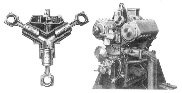
All three crankshafts rotated in the same direction. There was an additional, projecting crank at the end of each crankshaft. Attached to this crank was a triangular casting that connected the crankshafts together at the rear of the engine. This triangular member drove the generator and the water, oil, and Bosch fuel injection pumps. The fuel injection pump was positioned in the upper V of the engine.

Michel 3-cylinder section

Front and rear section view of the Michel three-cylinder opposed-piston engine. Note on the rear view, the triangular member connecting the three crankshafts and the rectangular scavenging air pump at its center.

A scavenging air pump was situated at the rear of the engine. This air pump was a rectangular frame formed integral with the triangular member that joined the crankshafts. The air pump took advantage of the frame’s rotary motion. The rectangular frame was sealed except for strategically placed passageways. A slide valve formed a partition within the frame and was fixed so that it could only move up and down. As the engine ran, the space within the frame on either side of the slide valve partition alternately expanded and contracted, creating a pumping action. Air was fed from the slide valve at 21-25 psi (1.4-1.7 bar) to the cylinders via internal passageways. Power from the engine was taken from the lower crankshaft.

In the early 1930s, Michel relocated to Hamburg, Germany and built a few of his redesigned, three-cylinder, opposed-piston engines. Like the cam engine, the cylinder group was somewhat modular, and additional groups could be added to the design. The engine with the smallest cylinder size had a 1.9 in (47 mm) bore and a 3.1 in stroke (80 mm). This engine had four three-cylinder groups and a total displacement of around 102 cu in (1.7 L) from its 12 cylinders. It produced 60 hp (45 kW) at 2,000 rpm and weighed 616 lb (279 kg).

Michel 3-cylinder

A Michel 3-cylinder group and its engine. This engine has one cylinder group. Note its short length and the single exhaust port of the lower cylinder..

A larger three-cylinder engine was built with a 2.6 in (67 mm) bore and a 4.7 in stroke (116 mm). Each three-cylinder group would displace around 75 cu in (1.2 L) and had an output of around 45 hp. A one cylinder group and a four cylinder group were made. The four cylinder group engine had a displacement of 299 cu in (4.9 L). This engine produced 180 hp (134 kW) at 2,000 rpm and weighed 1,188 lb (539 kg).

Although the engine’s size was not stated, a Michel engine was extensively run in a truck testbed and reportedly gave good results. However, the engine never entered production. The Michel line of engines was supposed to be made under license in the United Kingdom by Tekon Development Ltd and called the Stellar. However, it does not appear that any engines were made.

*Please note, the Hermann Michel discussed in this article is not the Nazi war criminal with the same name.

Michel 12-cylinder opposed piston engine

A Michel engine with four groups of three opposed-piston cylinders. This engine had a total of 12 cylinders. Note the four square exhaust ports on the lower cylinder bank.

Sources:
– “Two-Stroke-Cycle Internal-Combustion Engine” US patent 1,603,969 by Hermann Michel (granted 19 October 1926)
– “Engine, and Particularly Internal Combustion Engine” US patent 1,568,684 by Hermann Michel (granted 5 January 1926)
– “Comments on Crankless Engine Types” NACA Technical Memorandum No. 462, May 1928 (Translated from “Motorwagen” 20 November 1927) 12.8 MB
High Speed Diesel Engines by Arthur W. Judge (1941)
The Modern Diesel fourth edition no date Illiffe & Sons Ltd
New Motoring Encyclopedia (complete work 1937)
Ungewöhnliche Motoren by Stefan Zima and Reinhold Ficht (2010)

Nordberg 12-cylinder radial diesel

Nordberg Radial Stationary Engine

By William Pearce

In 1889, Bruno V. Nordberg founded the Nordberg Manufacturing Company (Nordberg) in Milwaukee, Wisconsin to build various industrial machines. In the 1910s, the company entered the heavy-duty diesel engine market. Over the years, Nordberg expanded its stationary engine catalog to include engines from 10 hp (7.5 kW) to over 10,000 hp (7,457 kW). To further expand its market, Nordberg developed a line of stationary radial engines in the 1940s.

Nordberg 12-cylinder radial diesel

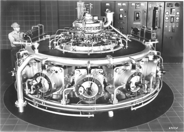
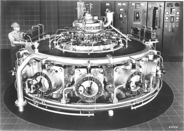
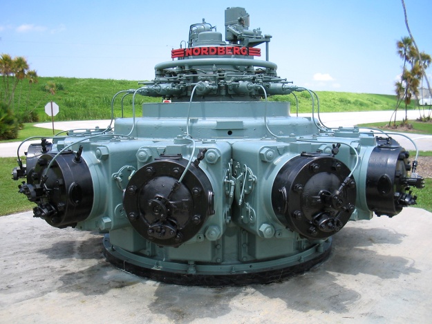
A 12-cylinder Nordberg diesel radial engine. This engine displaced 29,556 cu in (484.3 L) and produced around 2,000 hp (1,500 kW). Note the fuel injector in the center of the cylinder head.

The Nordberg radial offered several advantages over the stationary inline engines that were the current standard. With its cylinders horizontal, the Nordberg radial’s output shaft was in a vertical position. Although the engine was built primarily to generate power for the electrolytic reduction of aluminum, its arrangement was perfect for pumping applications. In addition, the configuration of the radial made it more compact and much lighter than a comparative inline engine. The Nordberg radial took up about half the space of an equally powerful inline engine and could be installed on a much lighter foundation.

The Nordberg radial was first introduced in 1947. The first engines were spark-ignition natural gas burning units that quickly established themselves as reliable and economical. These engines had two spark plugs located in the cylinder head. A single cam on the crankshaft actuated a gas valve for each cylinder. This gas valve allowed the natural gas into the incoming scavenging air for the cylinder.

Nordberg continued to develop the radial as its use spread to central power stations and various pumping applications, primarily for flood control and at sewage treatment plants. Nordberg soon developed a diesel version of the engine and a version that could run on a mixture of diesel and natural gas, which Nordberg dubbed Duafuel. The Duafuel engine could run on 100% diesel or as little as 5% diesel and 95% natural gas. This flexibility allowed the engine to operate with the most economical fuel mixture possible. In the diesel and Duafuel engines, the single cam now actuated a fuel pump for each cylinder, and the diesel fuel injector was in the center of the cylinder head.

Nordberg 12-cylinder radial spark ignition

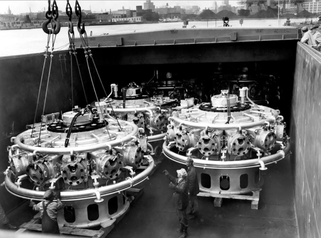
A number of Nordberg 12-cylinder spark-ignition radial engines are loaded into a barge in Milwaukee, Wisconsin. Note the two spark plugs in the cylinder head. This image also shows the base of the engine that would extend under the operating floor.

A later development was the addition of two turbochargers and intercoolers that increased the engine’s thermal efficiency while decreasing its fuel consumption. It is not clear whether or not the turbochargers were available for all engine types or just for the spark-ignition engines.

The Nordberg radial was a two-stroke engine with a 14 in (356 mm) bore and a 16 in (406 mm) stroke. Each cylinder displaced 2,463 cu in (40.4 L). There was an 11-cylinder (RTS 1411) and a 12-cylinder (RTS 1412) version of the radial engine, displacing a total of 27,093 cu in (444.0 L) and 29,556 cu in (484.3 L) respectively. The 11-cylinder engine was 12.125 ft (3.70 m) in diameter while the 12-cylinder was 13 ft (4.96 m). The engines had an operating speed of 400 rpm. Output varied depending on the engine’s configuration. A 11-cylinder spark-ignition engine was rated at 1,340 hp (1,100 kW), an 11-cylinder diesel was rated at 1,655 hp (1,235 kW), and a 12-cylinder diesel was rated at 2,125 hp (1,585 kW).

The 11-cylinder and 12-cylinder engines both had a crankshaft cast of high tensile alloy iron. The crankshaft had upper and lower main bearings. Neither engine had a master connecting rod; all connecting rods were of the articulated type.

Nordberg 11-cylinder radial crankshaft

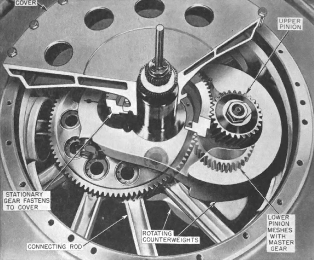
The crankshaft arrangement of the 11-cylinder Nordberg radial engine. All the connecting rods are attached to the master gear, which is not labeled in the image.

Each of the 11-cylinder engine’s connecting rods was attached to a large master gear via a knuckle pin. The master gear sat just above the connecting rods and was mounted on the crankshaft’s single crankpin. The master gear did not rotate, being restrained by two pinions and a stationary gear. The lower pinion rode on the master gear opposite the crankpin. The lower pinion was mounted on the same shaft as the upper pinion, which engaged a stationary gear at the top of the engine. Since the master gear was mounted on the crankpin, it moved in a circular motion with the crankshaft, and each knuckle pin subsequently moved in a circular motion. This design eliminated the need for a master connecting rod and provided good balance.

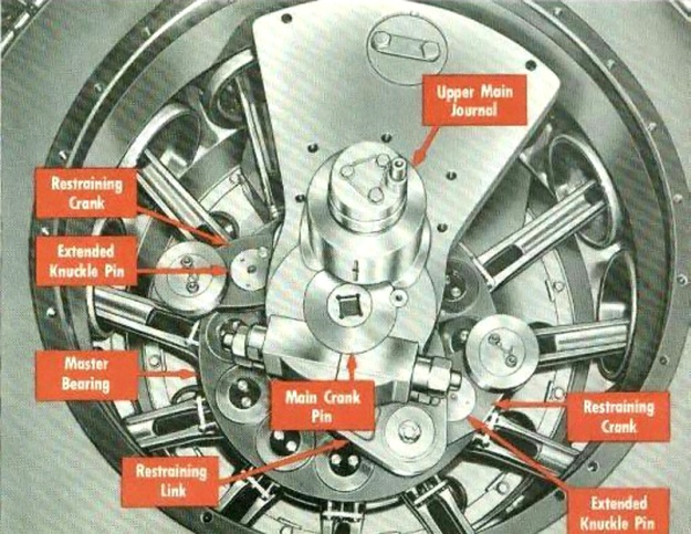
The 12-cylinder engine did not employ a master gear like the 11-cylinder engine. Instead, each connecting rod was attached to a master bearing via a knuckle pin. The master bearing was mounted on the crankshaft’s single crankpin. Two opposing connecting rods were rigidly connected to extended knuckle pins. Each of these extended knuckle pins carried a small restraining crank. The two restraining cranks were connected via a larger restraining link. This linkage prevented the master bearing from rotating but allowed it to move in a circular motion, like the master gear in the 11-cylinder engine. The 12-cylinder’s crankshaft arrangement was designed by Donald I. Bohn and awarded US patent 2,584,098 on 29 January 1952.

Nordberg 12-cylinder radial crankshaft

The crankshaft arrangement of the 12-cylinder Nordberg radial. Compare with the image of the 11-cylinder’s crankshaft.

The Nordberg radial engine had a single-piece cast iron crankcase and sub-base. Each cylinder was drawn to the crankcase by four long studs. The cylinders had intake ports positioned on the top side of the cylinder wall and exhaust ports on the lower side. The exhaust ports were closer to the head than the intake ports to allow for good cylinder scavenging. Either an electric or a geared blower pressurized the intake air and aided cylinder scavenging. The exhaust was expelled into a manifold located under the operating floor. The cylinders fired one right after another in successive order.

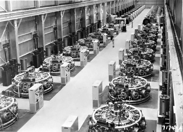
By the mid-1950s, the Aluminum Company of America (Alcoa) had 220 normally scavenged and 22 supercharged Nordberg radial engines installed in its Port Lavaca, Texas aluminum plant. Combined, these engines could produce 475,000 hp (354,207 kW). The engines were arranged in seven powerhouses, consisting of around 40 engines each. Kaiser Aluminum used 80 Nordberg radial engines in its reduction plant in Chalmette, Louisiana, accounting for 150,000 hp (111,885 kW).

Various smaller engine installations occurred in municipal power plants and pumping stations. In 1956, a 12-cylinder Nordberg radial engine was put into service at the municipal power plant in Winterset, Iowa. This engine is still in service as of 2016. In 1957, three 11-cylinder Nordberg radials were installed in the South Florida Water Management District Pump Station S-9, just west of Southwest Ranches, Florida. Each of these engines powered a pump with a 143,625 gpm (543,679 L/m) capacity. These Nordberg radials were retired in 1989 because of the scarcity of spare parts. One of the engines is currently on display at John Stretch Park in Lake Harbor, Florida. Nine 12-cylinder engines were installed in the Wastewater Treatment Plant at Deer Island (Boston), Massachusetts in 1968. Over five years, each engine had averaged 22,315 hours of operation. This equates to the engines running 12.25 hours a day, every day, for five years.

Nordberg 11-cylinder radial engines Alcoa

Forty Nordberg 11-cylinder spark-ignition radial engines in one of seven powerhouses at the Aluminum Company of America plant in Port Lavaca, Texas.

Over time, the engines did have problems. Because the cost to inspect the crankshaft was practically as much as replacing it, Alcoa adopted a policy to forgo inspections and run the engine until the crankshaft broke—and break it would. A number of other operators followed suit. Another issue was with excessive piston wear. The Deer Island installation had constant issues with various parts breaking, resulting in engines being off-line for extended periods. Since Nordberg was the sole supplier of parts and it could take some time for replacement parts to be supplied, cannibalism of engines occurred when more than one unit was down.

In 1970, the Nordberg Manufacturing Company was purchased by the Rexnord Corporation, also of Milwaukee, Wisconsin. In 1973, Nordberg/Rexnord stopped manufacturing diesel engines and parts. This, combined with the difficulties experienced by several operators, led to the phase out of the Nordberg radial engine. In 1987, Rexnord was purchased by Banner Industries of Cleveland, Ohio, and Nordberg was renamed Nordberg Inc. In 1989, Nordberg Inc was sold to the Finish company, Rauma-Repla Oy. At his time, Nordberg Inc manufactured mining equipment, mainly rock crushers. Through mergers, Rauma-Repla Oy became the Metso conglomerate in 1999. Nordberg Inc was renamed Metso Minerals Milwaukee, and continued to manufacture equipment until the factory was shut down on 30 June 2004. The closure ended 115 years of industrial machine manufacture.

Nordberg 11-cylinder radial engine FL

An 11-cylinder Nordberg diesel radial engine retired from pumping duties and now on display at John Stretch Park in Lake Harbor, Florida. (Image by Daniel Holth via Wikimedia Commons)

Sources:
Diesel and High Compression Gas Engines – Fundamentals by Edgar J. Kates (1954)
Nordberg Radial Engines (1958)
– “Radial Engine,” US patent 2,584,098 by Donald I. Bohn (awarded 29 January 1952)
http://www.oldengine.org/members/diesel/Nordberg/Nordmenu.htm and sub-pages
https://ssl.panoramio.com/photo/14133737
http://archive.org/stream/wastewaterengine10mass/wastewaterengine10mass_djvu.txt
https://cityofwinterset.org/electric-utility-information/

Fairbanks-Morse 32-14 engine

Fairbanks Morse Model 32 Stationary Engine

By William Pearce

In 1823, Thaddeus Fairbanks and his brother Erastus founded the E & T Fairbanks Company, which operated an iron foundry. In June 1832, Thaddeus patented the platform scale which quickly became the mainstay of the company. Back then, scales were integral to business as marine and railway shippers charged by weight. The E & T Fairbanks Company became the leading scale manufacturer in the United States and sold thousands of scales in the US, Europe, South America, and China.

Fairbanks-Morse 32-14 engine

Four-cylinder Fairbanks Morse 32E-14 engine.

In the 1870s, Charles Morse, an E & T Fairbanks Company distributor, was responsible for adding Eclipse Windmills and pumps to the E & T Fairbanks Company product list. Morse’s successful sales abilities enabled to him becoming a partner, and the company was eventually renamed Fairbanks Morse & Company.

In the late nineteenth century, Fairbanks Morse & Company continued to expand its now very diverse product line. The Company began producing oil and naptha engines in the 1890s. The Fairbanks Morse gas engine became a success providing power for irrigation, electricity generation, and oilfield work. Small power plants built by Fairbanks Morse were popular and evolved by burning kerosene in 1893, coal gas in 1905, and semi-diesel in 1913.

After the expiration of Rudolf Diesel’s American license in 1912, Fairbanks Morse entered the large engine business. Introduced in 1914, the company’s large Model Y semi-diesel stationary engine became a standard workhorse used by sugar, rice, and timber mills; mines, and other applications. The Model Y was available in sizes from one through six-cylinders, or 30 to 200 horsepower (22 to 149 kW).

Fairbanks-Morse 32E cutaway

Sectional view of a Fairbanks Morse 32E-14 engine illustrating the induction and exhaust.

Successor to the Model Y, the Y-VA engine was developed in Beloit, Wisconsin and introduced in 1924. It was the first high compression, cold start, full diesel developed by Fairbanks Morse without the acquisition of any foreign patent. The Y and Y-VA engines were made to run for long periods without stopping. By 1925 there were over 1,000 American cities generating electricity with Fairbanks Morse engines.

Around 1925 the Y-VA diesel was improved and renamed the Model 32 engine. The Model 32 was the culmination of many years of improvement upon the initial Model Y design. The improvements included various cylinder head designs, increased compression, and the eventual adoption of high-pressure injection and differential fuel injectors. To differentiate various cylinder heads and methods of induction on the Model 32 engine series, letter designations A thru E were used.

Fairbanks-Morse 32E crankshaft

The crankshaft and lower base for a four-cylinder 32E engine. The base for the individual cylinders mounted directly to the lower base.

The Model 32 was available in two cylinder sizes: 12 in (305 mm) bore with a 15 in (381 mm) stroke and 14 in (356 mm) bore with 17 in (432 mm) stroke. The 12×15 engine, known as -12, was available in one- through three-cylinder versions with each cylinder displacing 1,696 cu in (27.8 L) and producing about 40–50 hp (30–37 kW). The 14×17 engine, known as -14, was available in one- through six-cylinder versions with each cylinder displacing 2,617 cu in (42.9 L) and producing 60–75 hp (45–56 kW). Normal operating speed ranged from 257 to 360 rpm.

The two-stroke, water-cooled diesel of all cast iron construction was air started with 250 psi (17.2 bar). The only moving parts in the Model 32 were the pistons, connecting rods, crankshaft, oil pumps, fuel pumps, flywheel, and governor. The engine had no intake or exhaust valves. Air was drawn through the crankcase and into the cylinder when the piston uncovered an induction port. The air was then compressed by the piston as fuel was injected into the cylinder at 2,000 psi (137.9 bar) and ignited by the heat of the 500 psi (34.5 bar) compression. As the piston moved down on the power stroke, it uncovered the exhaust port, allowing the burnt gases to be expelled. Fuel consumption was around 0.39 lb/hp/hr (237 g/kW/h).

Fairbanks Morse Model 32E piston sectional, piston, and connecting rod assembly.

The Model 32 engines were in service for years in power stations, manufacturing plants, ice plants, flour mills, rock crushing plants, cotton gins, seed oil mills, textile mills, irrigation and drainage pumping stations, and many other locations. To give some idea of the service life of the engine, at 10,000 hours of operation the needle rollers on the piston pin should be replaced. At 20,000 hours the needle rollers should be replaced again and the piston pin should be rotated 180 degrees. At 40,000 hours, or 4.57 years of continuous operation, the piston pin and bushing should be replaced. The Model 32 was built at least into the 1940s. A number of engines were still in regular service at various locations into the 1970s, with at least one being run until 1991. The Indian Grave Drainage District in Quincy, Illinois still has three operational Model 32 engines, and three engines are on standby as back-up power generators in Delta, Colorado.

Today, stationary diesels are still used for power generation, pumping, and other purposes. Fairbanks Morse still exists in this field and also manufactures marine and locomotive diesels. As far as the Model 32 is concerned, some still exist in abandoned factories and power stations, while others have been saved and preserved. A few Model 32s are run for special events, enabling them to shake the ground once again.

Here is a video of 1936 four-cylinder Fairbanks Morse 32D-14 by accessgainer8. This engine is owned and occasionally operated by the Pottsville Historical Museum near Grant’s Pass, Oregon. The engine weighs around 60,000 lb (27,216 kg), and the flywheel alone weighs about 12,000 lb (5,443 kg).


Sources:
Fairbanks Morse: 100 Years of Engine Technology by C. H. Wendel (1993)
https://old.oldtacomamarine.com/fairbanks/manual.html
https://en.wikipedia.org/wiki/Fairbanks-Morse
http://www.oldtacomamarine.com/engines/fairbanks/index.html