By William Pearce
Maschinenfabrik Augsburg-Nürnberg (MAN) was involved with diesel engines since their inception. From 1893 to 1897, MAN* worked with Rudolf Diesel to develop his combustion cycle and build the first diesel engines. When Diesel’s engine first ran in 1894, it produced around 3 hp (2 kW) at 88 rpm. Just 15 years later, MAN was contracted to develop a diesel engine capable of 12,000 hp (8,948 kW) at 120 rpm.

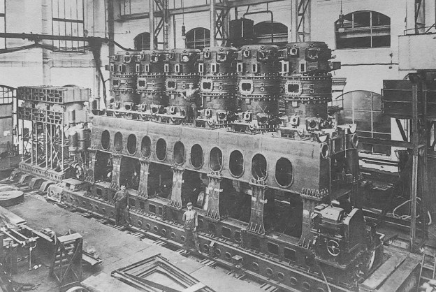
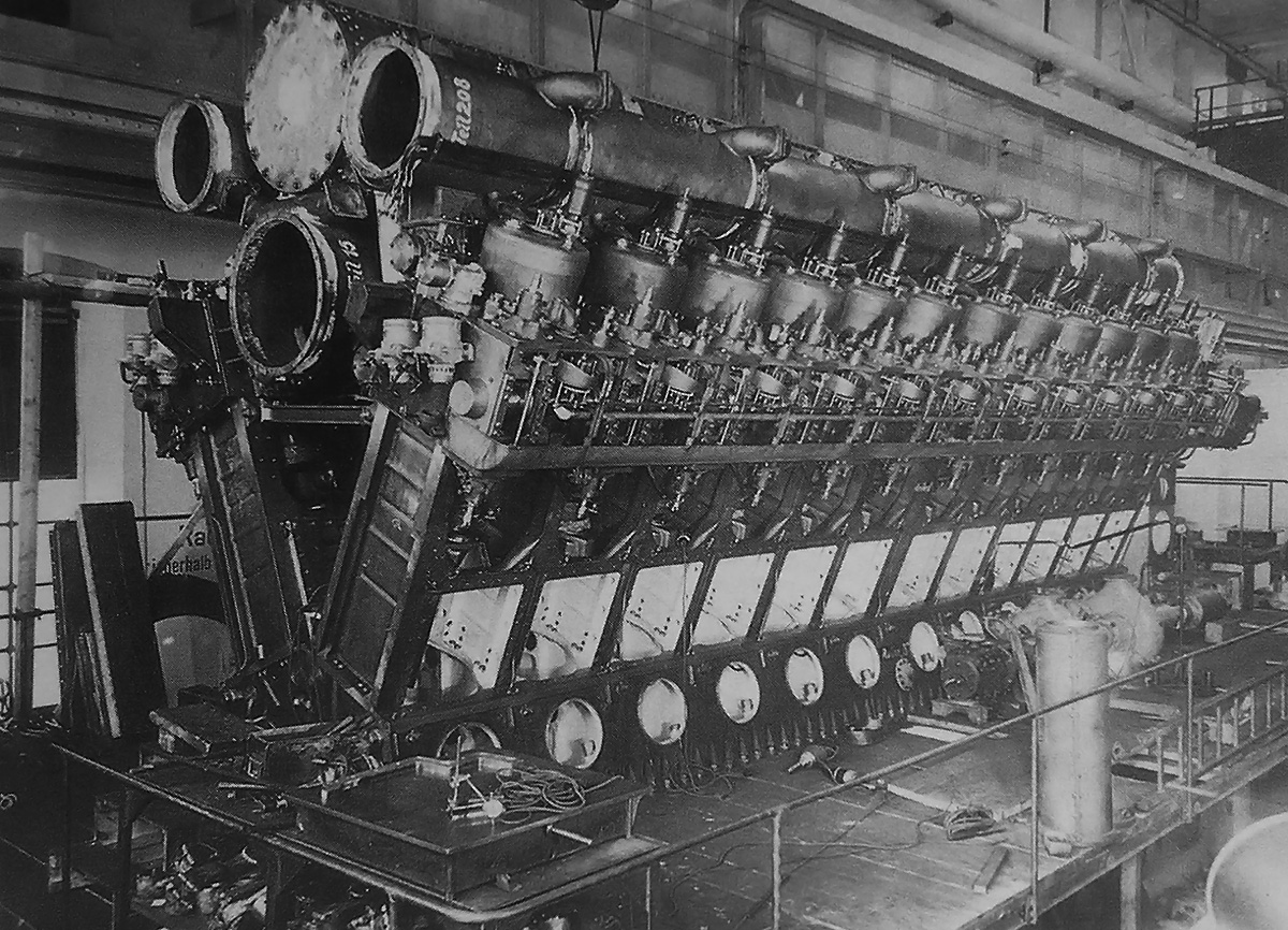
The MAN six-cylinder, double-acting, two-stroke, 12,000 hp, diesel marine engine under construction. The three workers provide a good reference as to the engine’s size.
The remarkable rise of diesel power caught the eye of many militaries. Anton von Rieppel, general manager of MAN at Nürnberg (Nuremberg), felt that diesels had matured enough to power the latest battleships. In August 1909, Rieppel proposed a new engine to the Reichsmarine (Germany Navy). By late 1909, a development contract was issued to MAN for the construction of a 12,000 hp (8,948 kW), six-cylinder diesel engine. Six of the engines would be needed to produce the 70,000 hp (52,199 kW) required for the latest German battleships. Given the uncharted territory MAN was traversing, a three-cylinder engine would be built first to prove that a six-cylinder engine could meet the desired specifications. Other companies were also contracted to build competing engines.
MAN’s design was an inline, two-stroke engine that used double-acting cylinders. Each of the closed cylinders had a combustion chamber at its top and bottom. Originally, each combustion chamber had four intake valves, four fuel valves, and two safety valves that were also used for air-starting the engine. The safety valves were located at the center of the combustion chamber. The locations of the remaining valves were split between passageways that branched off from either side of the upper combustion chamber. With the exception of the safety valves, the valves for each side of each combustion chamber were actuated by a single underhead camshaft. This configuration had a total of 20 valves for each cylinder and four camshafts for the engine. The final (seventh) combustion chamber design retained the four intake valves but had only two fuel valves and one safety valve (located in the upper combustion chamber). The changes lowered the number of valves per cylinder to 15. Exhaust ports were located in the middle of the cylinder and were covered and uncovered by the piston.

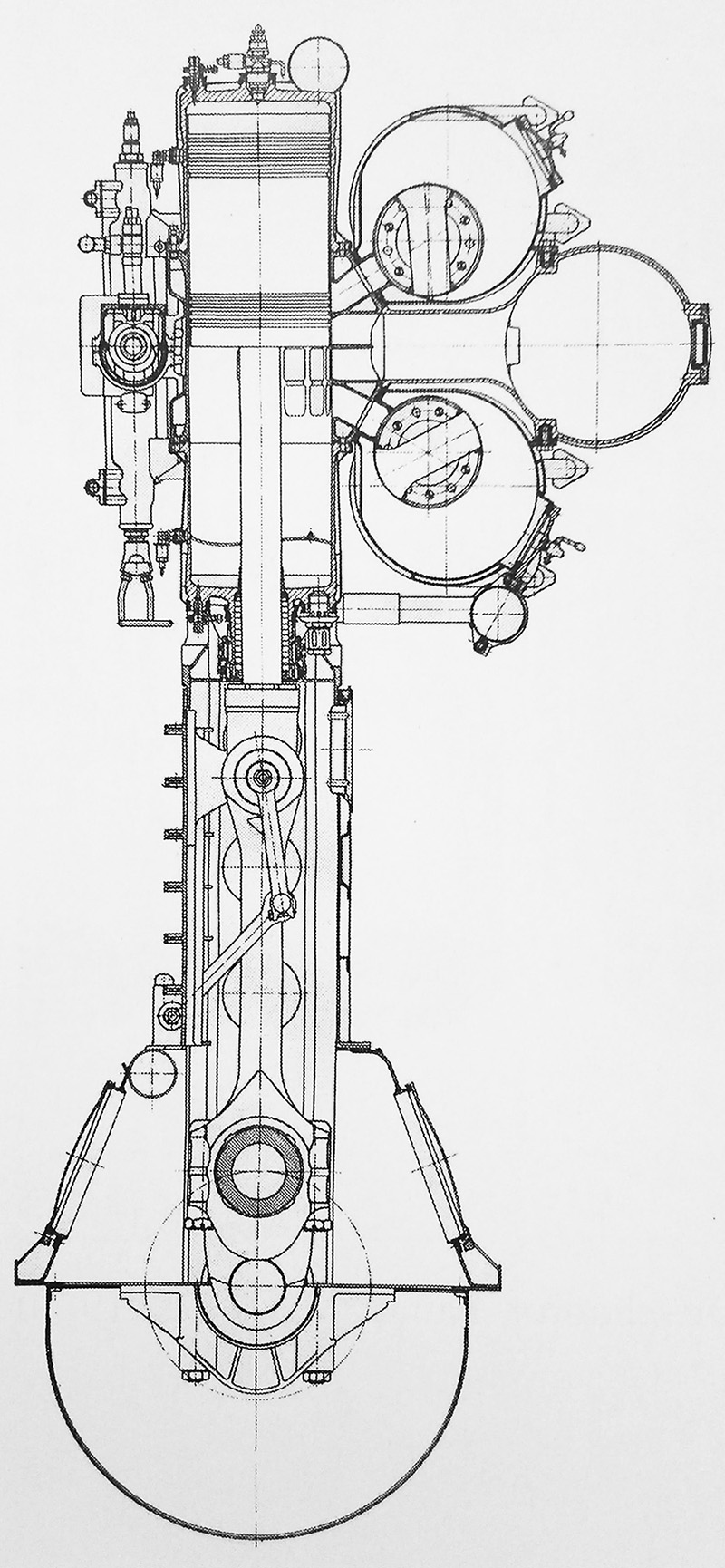
A drawing of the final cylinder design of the World War I engine. Fuel valves are on the left of the drawing, and intake valves are on the right. The exhaust manifold is positioned at the center of the cylinder. Note how the two piston halves are bolted together.
The double-headed piston was constructed of two parts. The lower part was connected to a non-articulating piston rod, and the upper part of the piston was bolted to the lower part. The piston rod was connected to the connecting rod via a cross head. The cross head slid in vertical channels on both sides of the inner crankcase. Oil was circulated through the piston to cool it. The oil flowed up through passageways in the piston rod and into the lower part of the piston. The oil then flowed to the upper part of the piston and down the center of the piston rod. The upper and lower combustion chamber sections were bolted to the center section of the cylinder, and the assembly was attached to the crankcase. A water jacket surrounded the cylinder. The center section of the cylinder and of the upper combustion chamber were made of cast iron. The crankcase, piston, lower combustion chamber, and many other components were made of cast steel. Each complete cylinder assembly was around 12 ft (3.5 m) tall, and the engine was over 24 ft 3 in (7.4 m) tall.
Each cylinder had a 33.4 in (850 mm) bore and a 41.3 in (1,050 mm) stroke. Since the piston was double-acting and there was a lower combustion chamber, each cylinder’s displacement was nearly doubled, as if it were two conventional cylinders. The upper combustion chamber displaced 36,359 cu in (595.8 L). However, the connecting rod passing through the lower combustion chamber took up around 3,021 cu in (49.5 L) of volume. Displacement for the lower combustion chamber was approximately 33,337 cu in (546.3 L). The cylinder’s total displacement was around 69,697 cu in (1,142 L). The three-cylinder test engine displaced 209,094 cu in (3,426 L), and the six-cylinder engine displaced 418,187 cu in (6,853 L). The engine drove three double-acting air pumps to scavenge the engine. Each air pump had a 52.0 in (1,320 mm) bore and a 31.5 in (800 mm) stroke.
The three-cylinder engine was first run on 12 March 1911. Severe delays occurred as technological issues were encountered. In January 1912, a failure caused the intake manifolds to explode, killing ten workers. By June 1913, the three-cylinder engine had met its requirement by producing 5,400 hp (4,027 kW) at 90% power. Construction of a six-cylinder engine followed.
The six-cylinder engine was first run on 23 February 1914. By September 1914, the engine was producing 10,000 hp (7,457 kW) at 130 rpm. By this time, World War I was underway; priorities shifted, and shortages were encountered. A single cylinder made a five-day run at over 2,000 hp (1,491 kW) in April 1915. On 24 March 1917, the six-cylinder engine produced 12,200 hp (9,098 kW) at 135 rpm for 12 hours. In April 1917, the engine passed its five-day acceptance test, running at 90% power and producing 10,800 hp (8,054 kW) at 130 rpm.
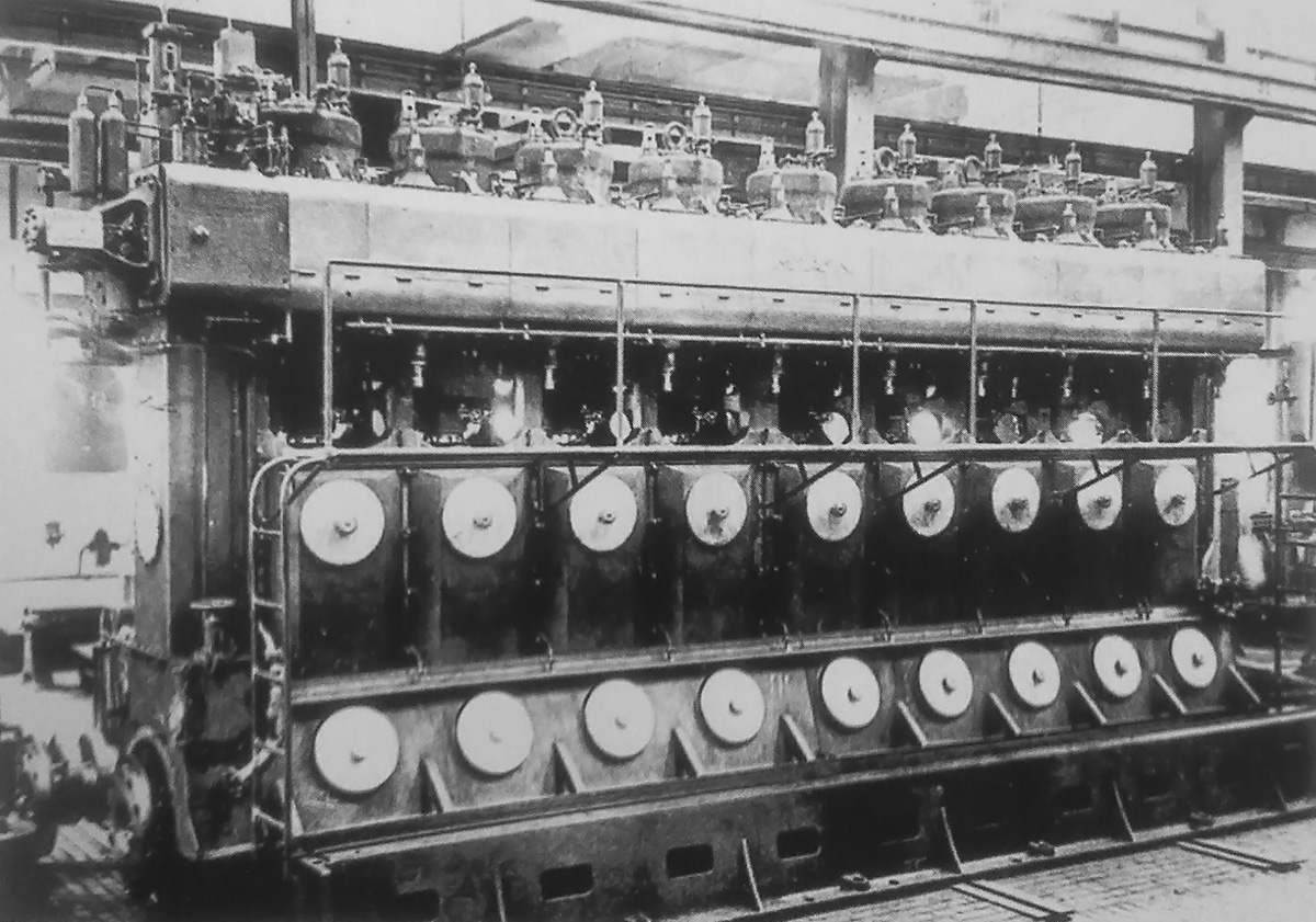
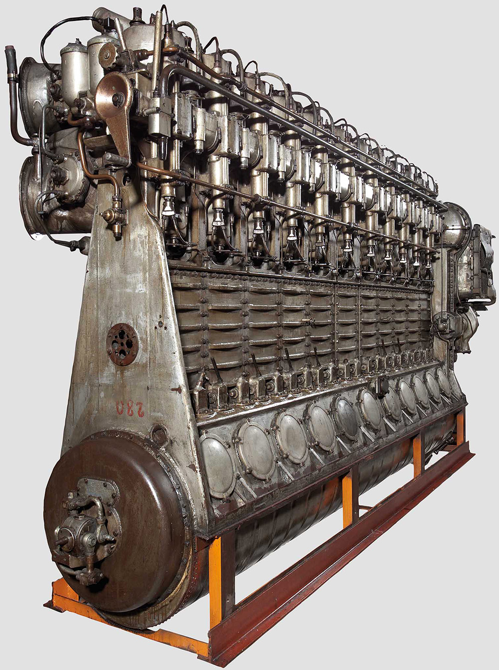
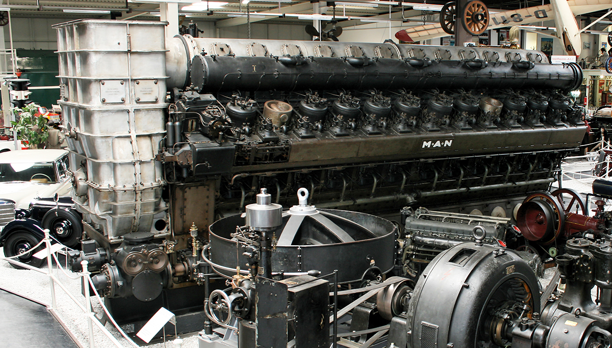
One of the MAN M9Z 42/58 engines built for installation in a Deutschland-class cruiser. At least 24 of the engines were made. The fuel injection pumps for each cylinder can be seen above and below the housing along the engine’s side.
By mid-1917, it was obvious that due to delays and the war, the engine would never be used, and the other five engines would never be built. MAN decided to test the engine to its limits. The engine test stand at MAN could not absorb the maximum anticipated power of the complete six-cylinder engine, so just one cylinder was run. On 16 October 1917, a single cylinder produced 3,570 hp (2,662 kW) at 145 rpm. If all six cylinders could match that performance, the complete engine would produce 21,420 hp (15,973 kW). The engine was later scrapped as a result of the Treaty of Versailles.
After World War I, Germany entered a period of economic ruin. It was not until 1926 that MAN designed the first engine in a new series of double-acting, two-stroke diesels. Overseen by engineer Gustav Pielstick, the new engines were similar in concept to the double-acting engine built during World War I, but they incorporated many new features. Pielstick had developed MAN submarine engines during World War I but did not work on the large double-acting engine.
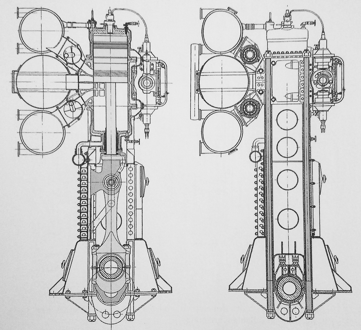
Sectional drawings of a MAN M9Z 42/58 engine. The rotary exhaust valves are positioned in a runner between the cylinder and the exhaust manifold. Note the long through bolts that pass through the entire engine.
The main structure of the new engines was made of steel plates welded together. This construction kept the engine rigid, but made it lighter than using cast components. Pairs of very long through bolts were positioned between the cylinders. They held the center part of the cylinder, crankcase, and crankshaft together and allowed for the disassembly of individual cylinders without compromising the integrity of the overall engine. The double-headed pistons were again made in two parts. From the top, the piston rod passed through the lower part of the piston, which was threaded to a shoulder on the rod. The upper part of the piston was threaded to the top of the piston rod. The skirt of the upper part of the piston slid into the skirt of the lower part. A sealed gap between the skirts allowed for the differential expansion of the individual piston halves. The piston was oil-cooled, like the World War I engine. The lower part of the piston rod was threaded into the cross head. Unlike the World War I engine, the cross head of the new series slid in a mount attached only to one side of the crankcase.
The new engine had no valves in the cylinder. In the middle of the cylinder were two rows of intake ports. The top row serviced the upper combustion chamber, and the bottom row serviced the lower combustion chamber. Air was forced into the cylinder by an auxiliary “pumping” engine. Fuel entered the cylinder via a single injector in the upper combustion chamber and two injectors on each side of the piston rod in the lower combustion chamber. The injectors were water-cooled and provided fuel to each cylinder at 3,625–4,350 psi (250–300 bar). Mounted to the side of the engine was a camshaft that drove the fuel injection pumps. Each cylinder had an upper and lower injection pump that respectively provided fuel to the upper and lower combustion chambers. Both pumps for each cylinder were controlled by a single lobe on the camshaft.
Sectional view of the MAN L11Z 19/30 shows that the rotary exhaust valves have been placed inside of the exhaust manifold to conserve space. Otherwise, the engine and cylinder are very similar to the larger engines.
Each combustion chamber had its own exhaust ports which led to separate manifolds for the upper and lower combustion chambers. The intake and exhaust ports were on the same side of each cylinder, and their relative positions allowed the cylinder to be loop scavenged. Rotary valves inside of the exhaust manifolds closed off the exhaust port before the piston and allowed the cylinder to be charged with incoming air. The valve itself was supported by a hollow tube through which water was circulated to keep the valve cool. Otherwise, the intake and exhaust ports were covered and uncovered by the piston. All the engines of the new series used the same basic cylinder design, but the engines differed in their bore, stroke, and number of cylinders.
After cylinder testing, the first complete engine built of this type was the D4Z 23/34. In MAN nomenclature, “4” represents the number of cylinders per bank and “23/34” the bore/stroke in cm. With its 9.1 in (230 mm) bore and 13.4 in (340 mm) stroke in a double-acting cylinder, the engine displaced around 6,591 cu in (108 L). The D4Z 23/34 produced 1,000 hp (746 kW) at 800 rpm. The D4Z 23/34 was run in 1927, and tests went well.
On 27 March 1928, the Reichsmarine contracted MAN to develop a larger engine for what would become the cruiser Leipzig. Four M7Z 30/34 engines powered the middle shaft in the Leipzig, while two other shafts were powered by steam turbines. The seven-cylinder M7Z 30/34 engine had a 11.8 in (300 mm) bore and a 13.4 in (340 mm) stroke. Each engine displaced around 19,624 cu in (321.6 L) and produced 3,100 hp (2,312 kW) at 800 rpm, giving a total of 12,400 hp (9,247 kW) for the four engines.
Compared to a steam turbine, the diesel engine took up less space, was simpler to operate, had nearly instant power, and could suffer damage without disastrous consequences. Shrapnel passing through a diesel engine would shut down the engine, most likely one of several. Shrapnel passing through a steam boiler would cause the boiler to explode, most likely killing some of the crew in the room.
Front view of the MAN L11Z 19/30. The camshaft ran to the side of the cylinders and controlled the fuel injection pumps. The handle on the front of the camshaft was used to adjust the camshaft when the engine was run in reverse. (Hermann Historica image)
The Reichsmarine decided to use only diesel-power for the Deutschland-class Panzerschiffe (armored ships) cruisers: Deutschland (later renamed Lützow), Admiral Scheer, and Admiral Graf Spee. In these ships, four nine-cylinder engines powered each of two propeller shafts. Engines were ordered in October 1928 for the Deutschland, on 9 January 1930 for the Admiral Scheer, and on 14 March 1931 for the Admiral Graf Spee. The engine type for these ships was the M9Z 42/58. With a 16.5 in (420 mm) bore and a 22.8 in (580 mm) stroke, the nine-cylinder, double-acting engine displaced 84,359 cu in (1,382 L). Each engine produced 7,100 hp (5,294 kW) at 450 rpm and weighed around 110 tons (100 tonnes). Combined, the eight engines provided a total of 56,800 hp (42,356 kW).
The artillery training ship (Artillerieschulschiff) Bremse was ordered in 1931. Powering the ship were eight M8Z 30/44 engines—four engines on each of the two propeller shafts. The M8Z 30/44 was the same engine used in the Leipzig but with an additional cylinder. The eight-cylinder M8Z 30/44 engine had a 11.8 in (300 mm) bore and a 13.4 in (340 mm) stroke. It displaced 22,427 cu in (367.5 L) and produced 3,350 hp (2,498 kW) at 600 rpm, giving a total of 26,800 hp (19,985 kW) for the eight engines.
The light cruiser Nürnberg was ordered in 1933 and used a combination of diesel engines and steam turbines, like its sister ship, the Leipzig. Four M7Z 32/44 engines powered the ship’s center shaft. The engines were larger than the ones used on the Leipzig but appear to have the same rated output. The M7Z 32/44 engine had a 12.6 in (320 mm) bore and a 17.3 in (440 mm) stroke. The seven-cylinder engine displaced 28,894 cu in (473 L) and produced around 3,100 hp (2,312 kW) at 600 rpm, giving a total of 12,400 hp (9,247 kW) for the four engines.
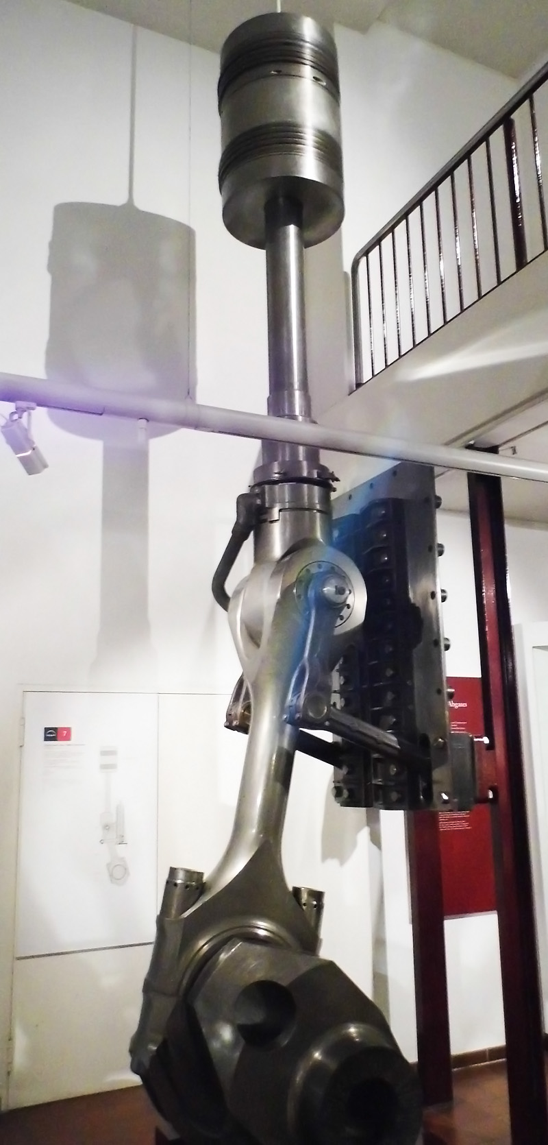
The piston, piston rod, connecting rod, and crankshaft section for a M9Z 65/95. The piston halves were threaded onto the piston rod, which was threaded to the cross head. An oil line can be seen attached to the cross head. The assembly is displayed in the Deutsches Museum in Munich. (enwo image)
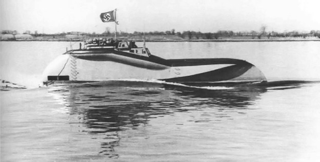
Around 1933, the Reichsmarine looked to steam turbines to fulfill their power needs, so the funding for MAN’s large diesel marine engines was severely cut. At the same time, a new engine was needed to power the latest German airships, the LZ 129 Hindenburg and LZ 130 Graf Zeppelin II. Pielstick adapted the basic design of the double-acting diesel to create a lighter, smaller engine, the L7Z 19/30. After the Daimler-Benz DB 602 engine was selected to power the airships, MAN added four cylinders to the L7Z engine to create the 11-cylinder L11Z 19/30 for marine use. The L11Z 19/30 used an engine-driven blower to provide intake air and cylinder scavenging. The engine had a 7.48 in (190 mm) bore, a 11.81 in (300 mm) stroke, and a total displacement of around 10,979 cu in (179.9 L). The L11Z 19/30 had a maximum output of 2,000 hp (1,491 kW) at 1,050 rpm and a continuous output of 1,400 hp (1,044 kW) at 900 rpm. The engine was approximately 157 in (4.0 m) long, 39 in (1.0 m) wide, and 98 in (2.5 m) tall. It weighed around 8,378 lb (3,800 kg) and was reversible. L11Z 19/30 engines were used in torpedo boats, with three engines installed in each Schnellboot S 14 to S 17 (S 14 was launched in January 1936) and four engines installed in the Versuchs Schnellboot VS 5 (launched in January 1941). The three L11Z 19/30 engines from S 15 survived. One engine is in the MAN Museum in Augsburg; one is in the Deutsches Museum in Munich, and one is in a private collection.
In 1935 and under Nazi leadership, the Reichsmarine was renamed Kriegsmarine. That same year, the Kriegsmarine initiated the design of new H-class battleships. The first of the ships would be powered by diesel engines. In 1938, the Kriegsmarine showed a renewed interest in large diesel marine engines, and MAN’s developmental funding was substantially increased. MAN developed the M9Z 65/95 engine for the H-class battleships in 1938. Four of these engines would power each of three shafts. The nine-cylinder engine had a 25.6 in (650 mm) bore, a 37.4 in (950 mm) stroke, and a total displacement of approximately 330,945 cu in (5,423 L). The M9Z 65/95 weighed around 248 tons (225 tonnes) and had a continuous output of 12,500 hp (9,321 kW) at 256 rpm and an emergency output of 13,750 hp (10,253 kW) at 265 rpm. The 12 engines gave a total of 150,000 hp (111,855 kW) for continuous operation and 165,000 hp (123,040 kW) for emergencies. In early 1939, 24 M9Z 65/95 engines were ordered by the Kriegsmarine, followed later in the year by another order for 24 engines. However, the orders were cancelled in late 1939, and only one test engine was built. This engine was tested in 1940 but was destroyed during an Allied air raid. A piston and rod assembly survived and is displayed in the Deutsches Museum in Munich. No H-class battleships were completed.
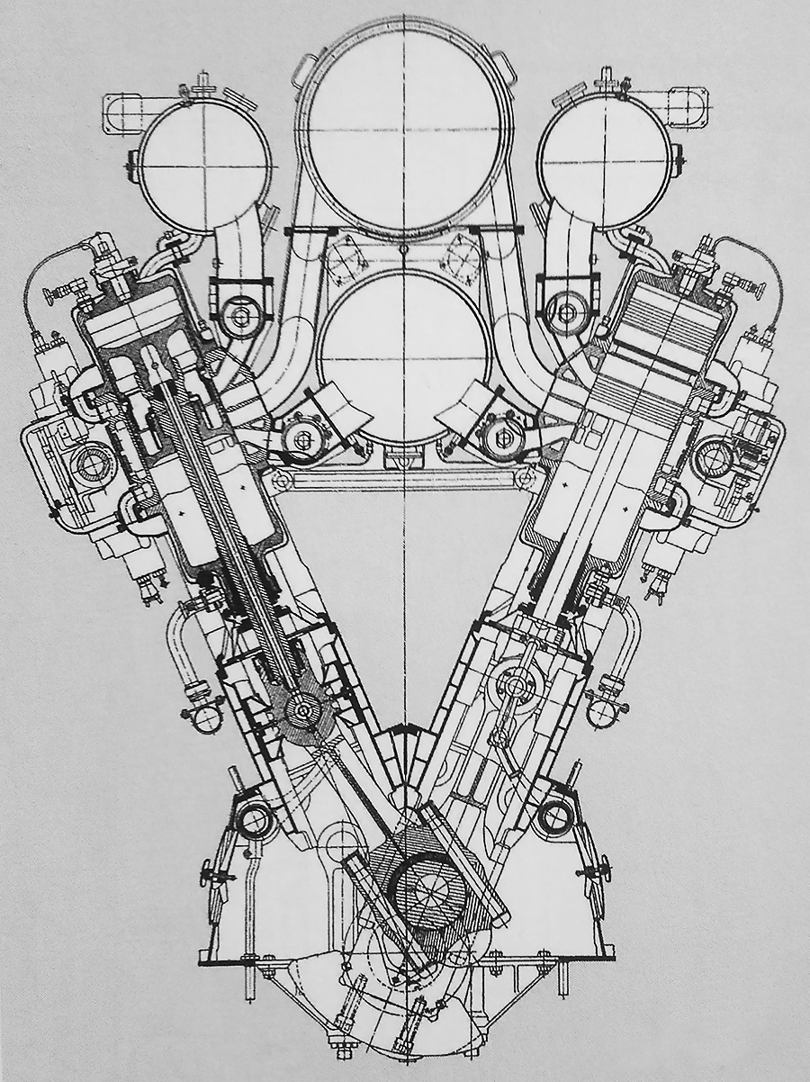
Sectional view of the MAN V12Z 32/44 engine illustrates a cylinder design similar to that used on the inline engines but with a completely different manifold arrangement. The large upper manifold was the intake, and the three other manifolds were for exhaust. Note the camshaft and fuel injection pumps on the outside of the cylinder banks.
By 1939, Pielstick used the basic cylinder design of previous engines to create larger and more powerful engines in a V configuration with 24 cylinders. The V-24 engines had a 45 degree bank angle and a new manifold arrangement, but the cylinder design and other components were similar to the previous inline engines. Positioned in the Vee of the engine was a lower exhaust manifold that collected the exhaust gases from the lower combustion chambers. Above this manifold was the intake manifold that serviced all the cylinders. Each cylinder bank had an upper exhaust manifold that collected the exhaust gases from the upper combustion chambers. These manifolds were positioned between the intake manifold and the respective cylinder bank. The fuel injection camshaft and pumps were located on the outer side of the cylinder banks. An engine-driven blower was positioned at the rear of the engine and fed air into the intake manifold.
The first V-24 was designated V12Z 42/58, and the engine was designed for the German O-class battlecruisers, with four engines powering each of two shafts. A third shaft was powered by a steam turbine. The V12Z 42/58 had a 16.5 in (420 mm) bore, a 22.8 in (580 mm) stroke, and displaced around 224,957 cu in (3,686 L). The 150.5-ton (136.5-tonne) engine produced 15,600 hp (11,633) at 450 rpm. The eight engines planned for use in the O-class would have produced a total of 124,800 hp (93,063 kW), but the O-class was cancelled, and no ships were built. One V12Z 42/58 engine was built and completed a 200-hour test run, generating a continuous 10,000 hp (7,457 kW) at 243 rpm.
A second, smaller V-24 engine was the V12Z 32/44 (sometimes called the V24Z 32/44). This engine was designed in 1940 for the Zerstörer 1942, of which one was built, the Z 51. Most sources state that the Z 51 was powered by six engines, with two engines powering each of three shafts. Other sources claim the center shaft had four engines and that the outer shafts had one engine each. The V12Z 32/44 had a 12.6 in (320 mm) bore and a 17.3 in (440 mm) stroke. The engine displaced around 99,066 cu in (1,623 L) and produced 10,000 hp (7,457 kW) at 600 rpm. A turbocharged version was planned that would increase output to 16,000 hp (11,931 kW). The V12Z 32/44 weighed 56.0 tons (50.8 tonnes), and the turbocharged version weighed 66 tons (60 tonnes). The Z 51 destroyer was nearly complete when it was sunk during an allied attack on 21 March 1945. Sources state that either four or six V12Z 32/44 engines were built. One engine was preserved and is on display in the Auto & Technik Museum in Sinsheim.
The MAN V12Z 32/44 engine under construction. The blower was mounted to the rear of the engine. Note the many access panels incorporated into the engine’s crankcase.
In the early 1950s, MAN again offered their double-acting, two-stroke diesel engines. The largest of these post-war engines was the D8Z 70/120. With a 27.6 in (700 mm) bore and a 47.2 in (1,200 mm) stroke, the eight-cylinder engine displaced 430,953 cu in (7,062 L) and produced 8,000 hp (5,966 kW) at 120 rpm. More efficient engines that required less maintenance overtook the double-acting, two-stroke power plants. Today, MAN continues to build diesels for automotive, industrial, and marine use.
*Maschinenfabrik Augsburg AG worked with Rudolf Diesel. The company merged with Maschinenbau-AG Nürnberg in 1898 to become Vereinigten Maschinenfabrik Augsburg und Maschinenbaugesellschaft Nürnberg (United Machine Factory Augsburg and Machinery Construction Company Nuremberg). In 1908, the company was renamed Maschinenfabrik Augsburg-Nürnberg (MAN).
The 24-cylinder MAN V12Z 32/44 engine as displayed in the Auto & Technik Museum in Sinsheim. The cars behind the engine give an indication of the engine’s size. Note the large blower housing attached to the engine. Six of these engines were to power the Z 51 destroyer. (Technik Museum Sinsheim und Speyer image)
Sources:
– “Multicylinder Combustion Engine” US patent 1,836,498 by Gustav Pielstick (granted 15 December 1931)
– “Internal Combustion Engine” US patent 1,887,661 by Gustav Pielstick (granted 15 November 1932)
– “Fuel Valve” US patent 1,919,904 by Gustav Pielstick (granted 25 July 1933)
– “Piston for Double Acting Internal Combustion Engines” US patent 1,922,393 by Gustav Pielstick (granted 15 August 1933)
– “Internal Combustion Engine” US patent 1,962,523 by Gustav Pielstick (granted 12 June 1934)
– “Housing for a Vertical Combustion Power Engine” US patent 1,969,031 by Gustav Pielstick (granted 7 August 1934)
– Diesel’s Engine by Lyle Cummins (1993)
– Ungewöhnliche Motoren by Stefan Zima and Reinhold Ficht (2010)
– Pocket Battleships of the Deutschland Class by Gerhard Koop and Klaus-Peter Schmolke (2014)
– http://www.deutsches-museum.de/en/collections/machines/power-engines/combustion-engines/diesel-engines/large-diesel-engines/marine-diesel-engine-1938/
– http://www.deutsches-museum.de/en/collections/machines/power-engines/combustion-engines/diesel-engines/large-diesel-engines/marine-engine-l11z-1930-1939/
– http://www.hermann-historica-archiv.de/auktion/hhm61.pl?f=NR_LOT&c=6902&t=temartic_M_GB&db=kat61_m.txt