
By William Pearce
Aircraft engine designer Frank Bernard Halford believed that an engine using a multitude of small cylinders running at a relatively high rpm would be smaller, lighter, and just as powerful as an engine with fewer, large cylinders running at a lower rpm. Halford was contracted by the British engineering firm D. Napier & Son (Napier) in 1928 and built the Rapier I (E93) in 1929 and the Dagger I (E98) in 1933. Both of these air-cooled engines had a vertical H configuration, with the Rapier having 16-cylinders and the Dagger having 24-cylinders. Ultimately, the 539 cu in (8.83 L) Rapier VI (possibly E106) produced 395 hp (295 kW) at 4,000 rpm in 1936, and the 1,027 cu in (16.84 L) Dagger VIII (E110) produced 1,000 hp (746 kw) at 4,200 rpm in 1938.

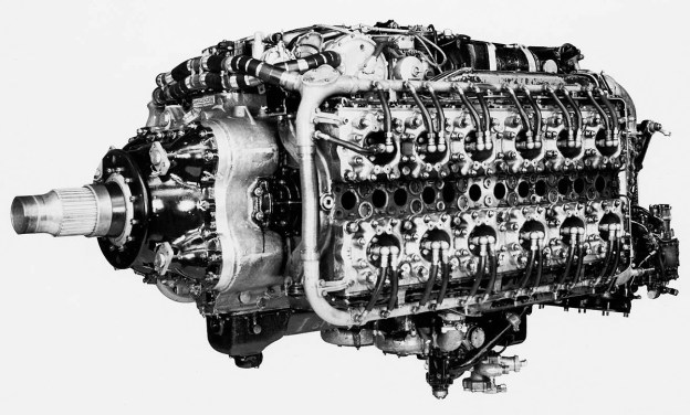
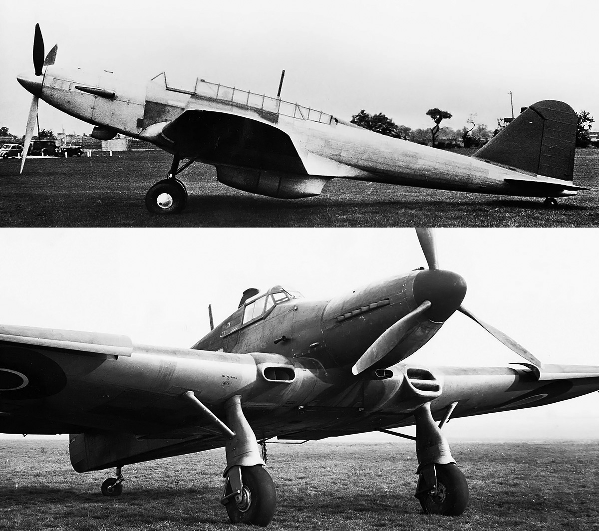
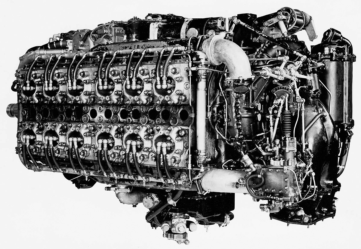
The Napier Sabre’s block-like exterior hid the engine’s complicated internals of 24-cylinders, two crankshafts, sleeve-valves, and numerous drives. The Sabre VA seen here was the last variant to reach quantity production. (Napier/NPHT/IMechE image)
Back around 1930, Napier Chairman Montague Stanley Napier and the company’s Board of Directors sought to diversify into the diesel aircraft engine field. Montague Napier and Bill Nowlan laid out the design for a liquid-cooled, vertical H, 24-cylinder diesel engine that used sleeve valves. Given the Napier designation E101, the engine had a 5.0 in (127 mm) bore, a 4.75 in (121 mm) stroke, and a total displacement of 2,239 cu in (36.68 L). Montague Napier passed away on 22 January 1931, but Nowlan continued design work under the direction of George Shakespeare Wilkinson, Ronald Whitehair Vigers, and Ernest Chatterton. Wilkinson took out a patent for the sleeve drive (GB363850, application dated 7 January 1931), and Vigers took out patents for sealing rings on a plug-type cylinder head (GB390610, application dated 15 February 1932) and sleeve-valves (GB408768, application dated 24 January 1933). It appears the E101 diesel was abandoned around 1933. However, two- and six-cylinder test engines had been built to test the sleeve-drive mechanism and prove the validity of the entire design.
In 1935, Halford joined Napier’s Board of Directors, acting as the company’s Technical Director. Halford was disappointed that the Rapier and Dagger were not more successful. He decided to design a new, larger, 24-cylinder, H-configuration engine that would be capable of 2,000 hp (1,491 kW). The design for at least part of the new engine was based on the E101 diesel. As he had done with the Rapier, Halford showed his design to George Purvis Bulman, the Deputy Director of Engine Research and Development for the British Air Ministry. Bulman was aware that designers of fighter aircraft were interested in such an engine and was able to arrange financial support for Napier to develop the H-24 engine. Halford’s 2,000 hp (1,491 kW) engine was given the Napier designation E107 and became known as the Sabre.
Serious design work on the Sabre started in 1936. The spark-ignition engine had a similar layout to the E101 diesel—both being liquid-cooled H-24s with sleeve-valves and possessing the same bore and stroke. Liquid-cooling was selected to efficiently reject the heat that the compact 2,000 hp (1,491 kW) engine generated, and a mixture of 70 percent water and 30 percent ethylene-glycol would be used. The Air Ministry enabled the free flow of information between Napier, Halford, and Harry Ralph Ricardo—a British engine expert who had been researching sleeve-valve engines for quite some time. With the engine technology known in the early 1930s, a perception existed that the poppet-valve engine had reached its developmental peak. Sleeve-valves were seen as a way to extract more power out of internal combustion engines. The sleeve-valve offered large, unobstructed intake and exhaust ports, a definite advantage to achieve a full charge into the cylinder and complete scavenging of the exhaust when the engine is operating at high RPMs.
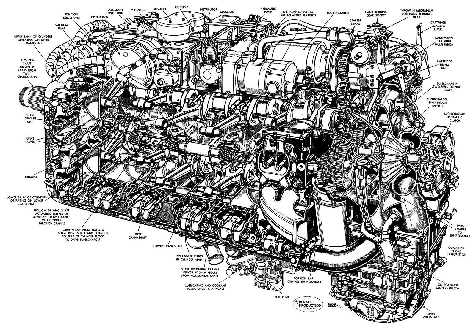
A drawing of a Sabre II, which was the main production variant. Note the two-sided supercharger impeller and the location of the supercharger clutch at the rear of the engine. The design of these components was changed for the Sabre IV and later variants. All accessories are mounted neatly atop the engine, away from any leaking oil, coolant, and fuel. (AEHS image)
The layout of the engine was finalized as a horizontal H-24. The Napier Sabre had a two-piece aluminum crankcase that was split vertically on the engine’s centerline. Sandwiched between the crankcase halves was an upper and lower crankshaft, each secured by seven main bearings. The center main bearing was larger than the rest, which resulted in an increased distance between the third and fourth cylinders in each bank. The crankshafts were phased at 180 degrees, and a cylinder for each crankshaft fired simultaneously. The single-piece, six-throw crankshafts were identical, and both rotated counterclockwise when viewed from the rear of the engine. Fork-and-blade connecting rods were used, with the forked rods serving the three front-left and three rear-right cylinders of the upper banks and the three front-right and three rear-left cylinders of the lower banks.
A 21-tooth spur gear on the front of each crankshaft meshed with two compound reduction gears, each with 31 teeth. A 17-tooth helical gear on the opposite side of each of the four compound reduction gears drove the 42-tooth propeller shaft counterclockwise. The drive setup created a double gear reduction, with the compound reduction gears operating at .6774 times crankshaft speed and the propeller shaft operating at .4048 times the speed of the compound reduction gears. The final gear reduction of the propeller shaft was .2742 crankshaft speed. A balance beam was mounted to the front of the two upper and the two lower compound reduction gears. A volute spring acted on each side of the beam to equally balance the tooth loading of the helical reduction gears on the propeller shaft. The forward ends of the compound reduction gears were supported by a gear carrier plate that was sandwiched between the crankshaft and the propeller shaft housing. The propeller shaft, balance beams, and volute springs were secured by the propeller shaft housing that bolted to the front of the engine.
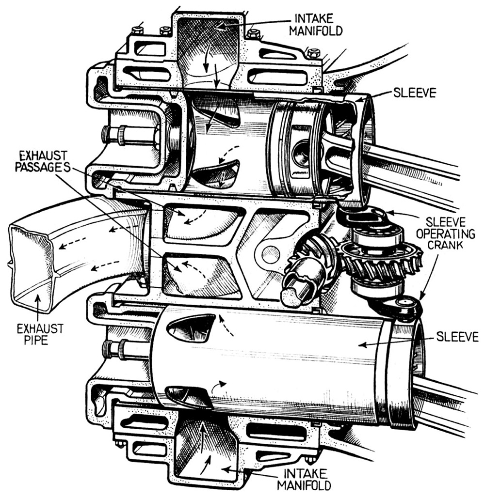
Sectional view through a Sabre cylinder block showing the upper and lower cylinders paired by the sleeve-valve drive. Intake and exhaust passageways were cast into the cylinder block, and coolant flowed through the hollow cylinder head. Note that the sleeve extends quite a distance between the cylinder head and cylinder wall. Also note the supercharger torsion bar extending through the hollow sleeve-valve drive shaft. (AEHS image)
Attached to each side of the crankcase was a one-piece, aluminum cylinder block that consisted of an upper and a lower cylinder bank, each with six cylinders. With the exception of a few installed studs, the left and right cylinder blocks were interchangeable. A two-piece sleeve-valve drive shaft was mounted between each cylinder block and the crankcase, and it ran between the upper and lower cylinder banks. Each sleeve-valve drive shaft was driven at crankshaft speed through a layshaft by an upper compound reduction gear. The left and right sleeve-valve drive shafts each had six worm gears with 11 teeth, and each worm gear drove the sleeves for an upper and a lower cylinder pair via a 22-tooth worm wheel made from bronze. This setup enabled the sleeves to operate at half crankshaft speed (and half the speed of the sleeve-valve drive shaft). The worm wheels and their separate housings were mounted to the inner sides of the cylinder blocks. Each worm wheel had an upper and lower sleeve crank, which were phased at 180 degrees. Each sleeve crank drove a sleeve via a ball joint mounted on a lug on the outer bottom of the sleeve. The rotational movement of the sleeve crank caused the sleeve to reciprocate and oscillate in the cylinder bore. In addition, when the sleeve for the upper cylinder was rotating clockwise, the sleeve for the paired lower cylinder rotated counterclockwise. Due to the opposite rotation, the sleeves for the upper and lower cylinder banks had different (mirrored) port shapes. Each sleeve-valve drive shaft was supported by 14 bearings, with each of the six worm wheel housings incorporating two bearings.
Each sleeve-valve drive shaft was hollow and had a supercharger torsion bar running through its center. The two supercharger torsion bars acted on a compound supercharger gear at the rear of the engine. Via a fluid-actuated clutch, the two-speed supercharger was driven at 4.48 times crankshaft speed in low gear (often called moderate supercharging, MS) and 6.62 times crankshaft speed in high gear (often called full supercharging, FS). The supercharger’s centrifugal impeller was double-sided. Air was drawn in through a four-barrel updraft SU (Skinner’s Union) suction carburetor and fed into the impeller. The air and fuel mixture was distributed from the supercharger housing via one of four outlets to a cast aluminum manifold that ran along the outer side of each cylinder bank.
When ports in the sleeve-valve aligned with three intake ports cast into the cylinder, the air and fuel mixture was admitted into the cylinder. As the sleeve rotated and ascended, the ports closed. Two spark plugs mounted parallel to one another in the cylinder head ignited the mixture, initiating the power stroke. As the sleeve rotated back and descended, the cylinder’s two exhaust ports were uncovered to allow the gasses to escape between the upper and lower cylinder banks. The sleeve’s stroke was approximately 2.5 in (64 mm), and its full rotation was approximately 56 degrees (its rotary movement being approximately 28 degrees back and forth from center). Each sleeve had only four ports, one of which was used for both intake and exhaust. Valve timing had the intake ports opening 40 degrees before top dead center and closing 65 degrees after bottom dead center. The exhaust ports opened 65 degrees before bottom dead center and closed 40 degrees after top dead center. Intake and exhaust ports were simultaneously partially uncovered for 80 degrees of crankshaft rotation—the last 40 degrees of the exhaust stroke and the first 40 degrees of the intake stroke. Twelve exhaust ports were located in a single line on each side of the engine, and each ejector exhaust stack served two ports—one for an upper cylinder and one for a lower cylinder.
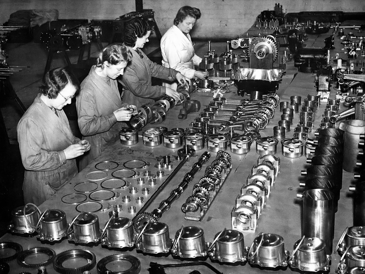
A Sabre engine being assembled. In the foreground are the individual cylinder heads with their sealing rings. In the row above the heads is a long, slim shaft that is the supercharger torsion bar. It passes through the two-piece sleeve-valve drive shaft. Further right are six sleeve-valve cranks, followed by their housings, and a set of 12 sleeves. The crank end of the sleeve is up, and note the helical grooves for oil control. Next is a row of pistons sitting inverted, each with rings and a piston pin. On the next row is a crankshaft being worked on and a set of six fork-and-blade connecting rods. Further to the right is another set of connecting rods that are already attached to the other crankshaft (out of frame). The lady furthest from the camera is working on the four compound reduction gears that will take power from the two crankshafts and deliver it to the propeller shaft, which is being held in a wooden fixture in front of her. On the far left, behind the ladies, is a Sabre cylinder block with numerous studs to attach the cylinder bank. Next is an upper accessory housing with some accessories attached. Last is a lower accessory housing with fuel, water (both external), and oil (internal) pumps.
The forged aluminum pistons were rather short with a minimal skirt, which was required for the engine’s relatively short stroke, use of sleeve-valves, and narrow width. Each flat-top piston had two compression rings above the piston pin, with one oil scraper ring below. The top ring was later tapered to prevent the buildup of carbon. The piston operated directly in the sleeve-valve, which was .09375 in (2.4 mm) thick and made from forged chrome-molybdenum steel. When the piston was at the bottom of its stroke, it was almost completely removed from the cylinder and supported only by the sleeve. The sleeves had a hardened belt on their inner diameter at the top of the piston stroke. Helical grooves inside the lower part of the sleeve helped prevent excessive oil accumulation on the sleeve walls. Oil was controlled further by an oil scraper fitted at the bottom of the sleeve between its outer diameter and the cylinder. The top of each cylinder was sealed by a cast aluminum cylinder head. The cylinder head acted as a plug atop the cylinder and was sealed against the sleeve by a compression ring. The top of the sleeve extended between the cylinder head and the cylinder wall. The cylinder head incorporated coolant passages that communicated with passages in the cylinder block. The engine had a compression ratio of 7.0 to 1.
The upper and lower crankshafts also respectively drove upper and lower auxiliary drive shafts. These auxiliary drive shafts were contained in their own separate housings which were respectively attached to the upper and lower sides of the assembled engine. The upper auxiliary drive shaft powered a vacuum pump, the propeller governor, two distributors, two magnetos, a generator, an air compressor, a hydraulic pump, and an oil pump for the supercharger. All of this equipment was mounted as compactly as possible to the top of the engine. The lower auxiliary drive shaft powered left and right coolant pumps, a fuel pump, and various oil pumps. The coolant and fuel pumps were mounted below the engine, while the oil pumps were internal. The coolant pumps provided a combined flow of 367 US gpm (306 Imp gpm / 1,389 L/min). Also mounted atop the engine and geared to the rear of the upper crankshaft was the Coffman combustion starter unit. The starter had a five-cartridge capacity.
The upper and lower cylinders were numbered 1–12, starting from the left rear and proceeding clockwise to the right rear. With the simultaneous firing of a cylinder for each crankshaft, the engine’s firing order was Top 1/Bottom 6, T9/B10, T5/B2, T12/B7, T3/B4, T8/B11, T6/B1, T10/B9, T2/B5, T7/B12, T4/B3, and T11/B8. Four mounting pads on the underside of the engine attached it to the support structure in the aircraft. The basic design of the Sabre enabled easy access for routine maintenance. Once the aircraft’s cowling was removed, crews had unobstructed access to all of the spark plugs on the sides of the engine and all accessories mounted atop the engine.

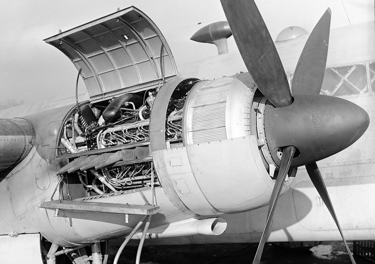
A Sabre IIB being pulled from a Typhoon IB. Note the coolant header tank at the front of the engine, the accessories packaged atop the engine, the two-into-one exhaust stacks, and the hydraulic supercharger clutch at the rear of the engine. The cylinder housing for the five-cartridge Coffman starter can be seen above the supercharger.
The Napier Sabre I (E107) engine had a 5.0 in (127 mm) bore and a 4.75 in (121 mm) stroke. With a bore diameter greater than the stroke length, the Sabre was an over-square engine. Each cylinder displaced 93.2 cu in (1.53 L), and the engine’s total displacement was 2,239 cu in (36.68 L). At 3,700 rpm, the Sabre I produced 2,050 hp (1,529 kW) at 2,500 ft (762 m) with 7 psi (.48 bar) of boost and 1,870 hp (1,394 kW) at 14,500 ft (4,420 m) with 8 psi (.55 bar) of boost. The engine was 81.1 in (2.06 m) long, 40.0 in (1.02 m) wide, and 51.1 in (1.30 m) tall. The Sabre I weighed 2,360 lb (1,070 kg).
Sabre development at Napier’s works in Acton, England progressed quickly, and single-, twin-, and six-cylinder test engines were all running by the end of 1936. The first of four 24-cylinder prototype engines was run on 23 November 1937, and the Air Ministry ordered six additional test engines by December. On 17 January 1938, the Sabre passed initial acceptance tests with a rating of 1,350 hp (1,007 kW), and on 3 March, the Air Ministry ordered two Sabre-powered Hawker Typhoon fighter prototypes. Also in March, the engine passed a 50-hour test that included a peak output of 2,050 hp (1,529 kW). All ordered engines were completed by the end of 1938 and were running on test stands by February 1939. While testing continued, the Sabre I was first flown in a Fairey Battle on 31 May 1939, piloted by Chris Staniland. As installed in the Battle, the Sabre had a single exhaust manifold on each side of the engine that collected the exhaust from all 12 cylinders.
In July 1939, the Air Ministry ordered 100 production engines and material for another 100 engines. In August, the Sabre passed a type test with a rating of 1,800 hp (1,342 kW). On 8 October 1939, an order for 250 Typhoons was placed, and on 24 February 1940, the Typhoon prototype (P5212) made its first flight, piloted by Philip G. Lucas. Three four-into-one exhaust manifolds were originally installed on each side of the Typhoon’s Sabre, but these were quickly replaced by what would become the standard two-into-one exhaust stacks. In March 1940, Napier created its Flight Development Establishment at Luton, England for flight testing the Sabre and developing installations for the engine. By all accounts, the Sabre continued to perform well, although some vibration issues were experienced with the Typhoon. In June 1940, the engine passed a 100-hour type test with a maximum output of 2,050 hp (1,529 kW) at 3,700 rpm, making the Sabre the first engine to have a service rating over 2,000 hp (1,491 kW).
The installation of Sabre engines on the Fairly Battle (top) and Folland F.108 (bottom) were well executed. Two Battles and three Fo.108s were employed to test the Sabre, and these aircraft provided valuable information about the engine.
Since mid-1938, a plan was underway to use an uprated Sabre engine in a specially-designed aircraft for a speed record attempt. The special engine produced 2,450 hp (1,827 kW) at 3,800 rpm with 9.2 psi (.63 bar) of boost and was first run on 6 December 1939. Installed in the Napier-Heston Racer, the combination first flew on 12 June 1940, piloted by G. L. G. Richmond. Difficulties with the new engine and airframe resulted in a hard landing that damaged the aircraft beyond repair. The Sabre engine installed in the Napier-Heston Racer featured two six-into-one exhaust manifolds on each side of the engine.
Around November 1939, the Air Ministry ordered 500 examples of the Typhoon. This order was temporarily suspended due to the Battle of Britain but was reinstated in October 1940. At that time, Napier began work to produce additional Sabre engines for the Typhoon order, but production was still a very limited affair. These early engines were limited to 25 hours before being removed for major inspection. The first production Typhoon IA (R7576) flew on 27 May 1941, with other aircraft soon to follow. Nearly all Sabre I engines were used in Typhoon IAs.
Around 1940, consideration was given to producing the Sabre in the United States. A Sabre I was sent to the Army Air Corps Technical Branch at Wright Field, Ohio, where it was inspected by a number of aircraft engine and automotive manufacturers in early 1941. While the engine was judged to be impressive overall, the general consensus was that the Sabre’s complexity and its unproven sleeve-valves made it too much of a risk to justify production in the United States.
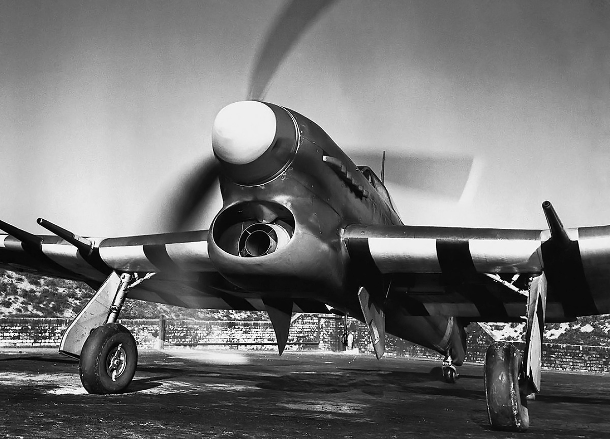
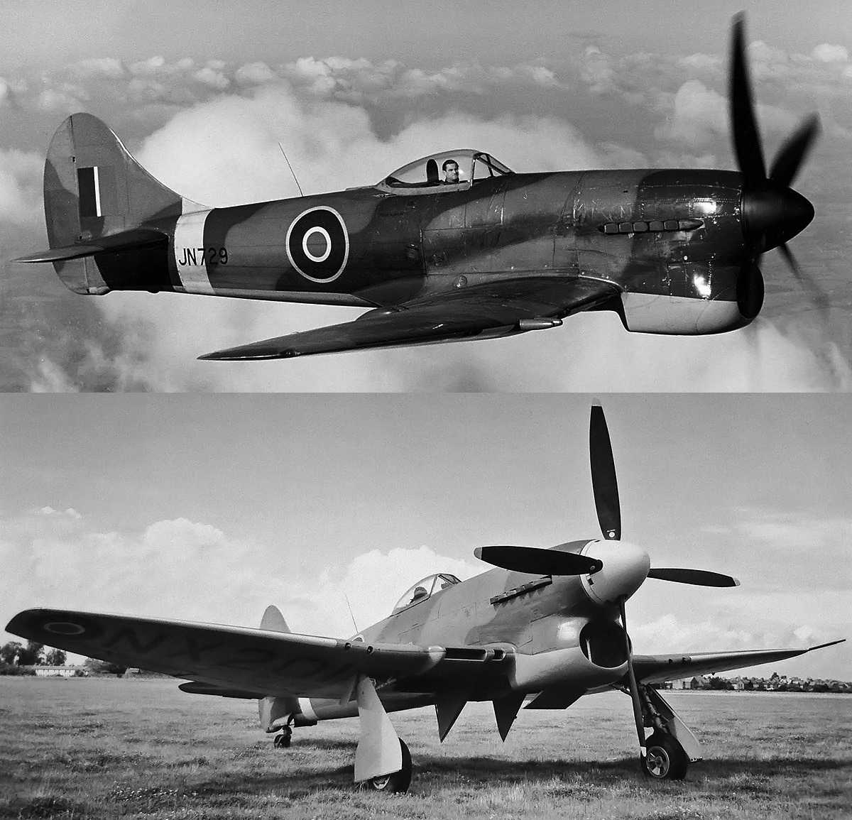
With its 14 ft (4.27 m) three-blade propeller turning, this early Typhoon IB warms up its Sabre engine for a flight. The Typhoon IB had four 20 mm cannons, while the earlier IA had 12 .303 machine guns. At the center of the radiator is the open carburetor intake, which was later covered by a momentum air filter. Note the underwing identification/invasion stripes.
Napier continued to develop the engine as the Sabre II, and the first production Sabre II was completed in January 1941. The Sabre II produced 2,090 hp (1,559 kW) at 3,700 rpm at 4,000 ft (1,219 m) with 7 psi (.48 bar) of boost and 1,735 hp (1,294 kW) at 17,000 ft (5,182 m). Sabre II engines were first installed in Typhoons on a trial basis in June 1941, and the engine was cleared for 50 hours between major inspections around this time. The Sabre II would ultimately replace the Sabre I in Typhoon IAs and IBs, and the Sabre I was phased out around October 1941. In addition to the Typhoon, the Sabre II also powered the Martin-Baker MB3 fighter, which made its first flight on 31 August 1942, and the Hawker Tempest V fighter prototype (HM595), which made its first flight on 2 September 1942, piloted by Lucas. The Tempest V was a new aircraft developed from the Typhoon.
The Folland Fo.108 was built to Air Ministry Specification 43/37 calling for an engine testbed aircraft. Three of the fixed-gear monoplanes were delivered to Napier’s Flight Development Establishment at Luton in 1941 and were initially fitted with Sabre II engines. The aircraft were to serve Napier for several years testing various versions of the Sabre engine. One of the Sabre-powered aircraft was lost on 14 September 1944.
The Sabre III was similar to the II but was intended for higher engine speeds. The Sabre III was selected for the Blackburn B-37 Firebrand carrier strike aircraft. At 4,000 rpm, the Sabre III had a takeoff rating of 2,250 hp (1,678 kW) and military ratings of 2,310 hp (1,723 kW) at 2,500 ft (762 m) with 9 psi (.62 bar) of boost and 1,920 hp (1,432 kW) at 16,000 ft (4,877 m). At 3,500 rpm, the engine had a normal rating of 1,890 hp (1,409 kW) at 5,000 ft (1,524 m) and 1,630 hp (1,215 kW) at 16,500 ft (5,029 m). The Firebrand (DD804) was first flown on 27 February 1942. However, with production priority going to the Typhoon, the Ministry of Aircraft Production decided to reengine the Firebrand with the Bristol Centaurus sleeve-valve radial engine. Only around 24 of the Sabre-powered versions were built.
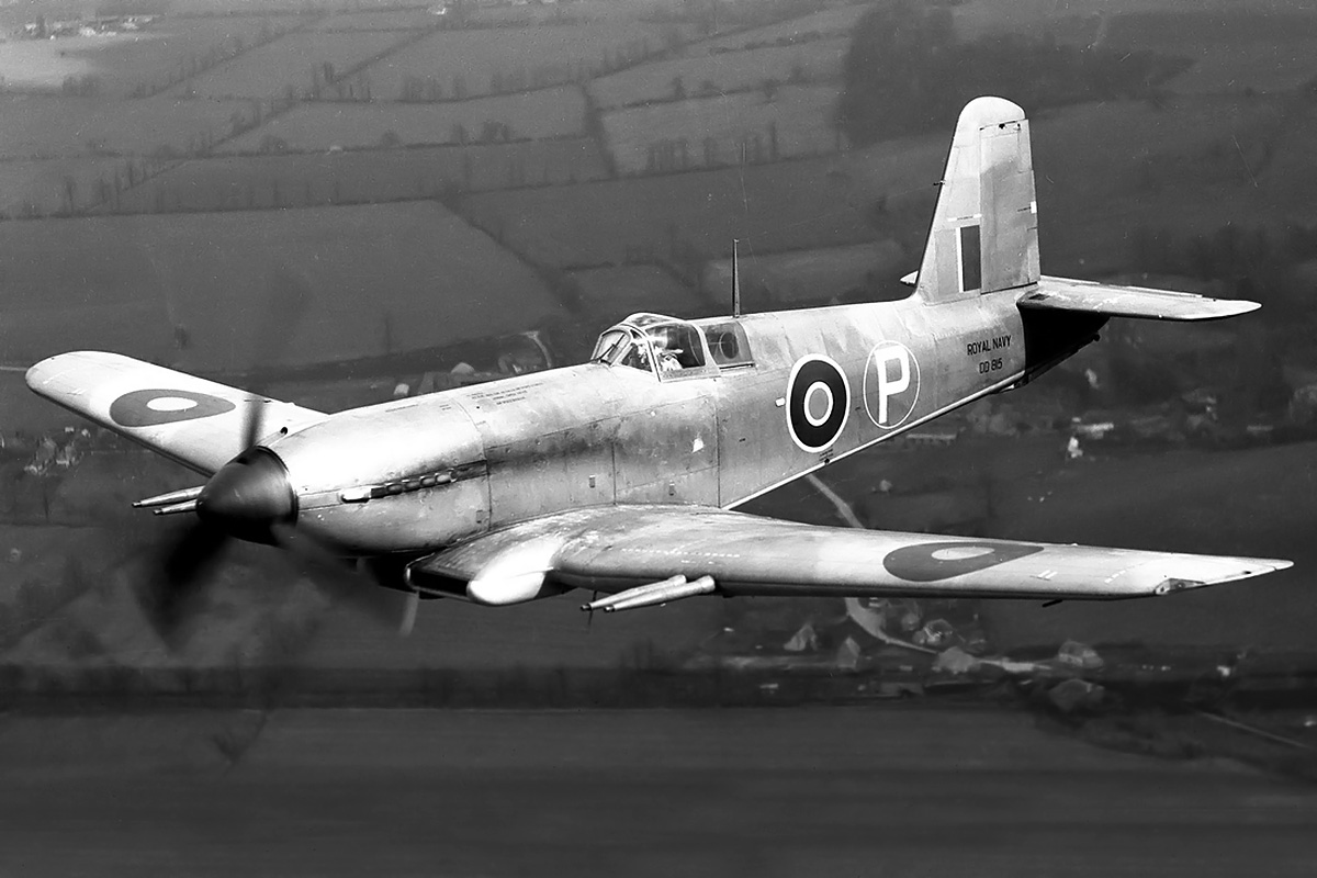
The Blackburn Firebrand, was to be powered by the Sabre III. However, Sabre engine production was allocated to the Typhoon, and the Firebrand was reengined with the Bristol Centaurus. Pictured is DD815, the third Firebrand Mk I prototype.
With production engines in production airframes, Sabre reliability issues were soon encountered. After running for a few hours, sometimes not even passing initial tests, Sabre engines began to experience excessive oil consumption and sleeve-valves cracking, breaking, seizing or otherwise failing. Examinations of numerous engines found sleeves distorted or damaged. Since the Sabre’s main application was the Typhoon, it was that aircraft that suffered the most. To make matters worse, the Typhoon was experiencing its own issues with in-flight structural failures. Other aircraft suffered as well. On 12 September 1942, the Sabre II engine in the MB3 failed; the subsequent crash landing destroyed the prototype and killed the pilot, Valentine H. Baker.
The Sabre had performed admirably during testing, but the production engines were encountering issues at an alarming rate. The early engines were built and assembled by hand. Parts with small variances were matched to obtain the desired clearances and operation. This was a luxury that could not be afforded once the engine was mass produced. The sleeves were found to be .008 to .010 in (.203 to .254 mm) out of round. This caused the cascading failure of other components as the engine was operated. In addition, the piston was forming a ridge in the sleeve, leading to excessive wear and the eventual failure of the piston rings, piston, or sleeve.
Carbon build-up was causing issues with the lubrication system. While in flight, aeration of the oil resulted in a heavy mist of oil flowing from the breather and coating the cockpit, obscuring the pilot’s view. The Coffman cartridge starter caused other issues; its sudden jolt when starting the engine occasionally damaged sleeve-drive components, setting up their inevitable failure. Part of the starting issue was that the sudden rotation of the engine with a rich mixture washed away the oil film between the pistons and sleeves. Finally, service crews were misadjusting the boost controller, creating an over-boost situation that led to detonation in the cylinders and damaged engines.
The Tempest I was powered by the Sabre IV engine. At 472 mph (760 km/h), the aircraft was the fastest of the Tempest line. The Tempest I was rather elegant without the large chin radiator, and the wing radiators were similar to those that would be used on the Sabre VII-powered Fury.
Napier worked diligently to resolve the issues. A detergent-type oil was used to prevent the build up of carbon on internal components. A centrifugal oil separator was designed to deaerate the oil and was fitted to Sabre engines already installed in Typhoons. Changes were made to the starter drive, and a priming mixture of 70 percent fuel and 30 percent oil was utilized to maintain an oil film in the cylinders. The boost controllers were factory sealed, and severe repercussions were put in place for their unauthorized tampering.
The issues with sleeve distortion were the most serious and vexing. Methods were devised to measure the sleeve with special instruments via the spark plug hole. While this helped to prevent failures, it also caused the withdrawal of low-time engines as sleeves became distorted. To fix the issue, different sleeve materials were tried along with different processes of manufacture, but nothing seemed to work. The supply of Sabre engines fell behind the production of Typhoon aircraft, and engineless airframes sat useless at manufacturing facilities. The engine shortage was so severe that a good Sabre would be installed in a Typhoon to ferry the aircraft to a dispersal facility. The engine would then be removed, returned to the aircraft factory, and installed in another Typhoon to shuttle that aircraft away, repeating the process over and over.
In October 1941, Francis Rodwell ‘Rod’ Banks replaced Bulman, who was, at the time, the Director of Engine Production for the Ministry of Aircraft Production. Bulman was back in Engine Research and Development and continued to work with Halford and Napier to resolve issues with the Sabre. Banks suggested that Napier work with the Bristol Engine Company on a suitable sleeve for the Sabre. Bristol had been manufacturing radial sleeve-valve engines since 1932, and their Taurus engine had the same 5.0 in (127 mm) bore as the Sabre. Napier was apparently not interested in pursuing that possible solution, so Banks went directly to Bristol and had them machine a pair of sleeves for use in the Sabre two-cylinder test engine. The Bristol sleeves were made from centrifugally cast austenitic steel comprised of nickel, chromium, and manganese. The sleeve was nitrided to increase its hardness and was not more than .0002 in (.005 mm) out of round. The Sabre two-cylinder test engine with the Bristol sleeves ran 120 hours without issue. Banks then had Bristol produce 48 sleeves for two complete 24-cylinder Sabre test engines. Bristol became unhappy with sharing its components and processes with a competitor, and Napier was still hesitant to utilize Bristol’s materials and techniques. Bristol’s position is somewhat understandable considering it took them years and a sizable fortune to develop the materials and procedures to reliably manufacture their sleeves.
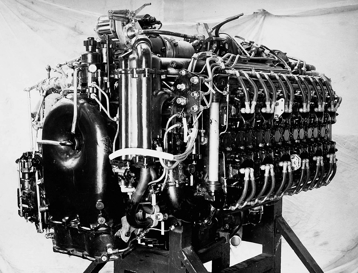
The Sabre VA had a one-sided supercharger impeller, a relocated supercharger clutch, and a two-barrel injection carburetor. These refinements were introduced on the Sabre IV. The Sabre VA powered the Tempest VI. (Napier/NPHT/IMechE image)
With the Air Ministry’s push, Napier was taken over by English Electric in December 1942. The new management was happy to accept any assistance from Bristol, and Bristol was now more willing than ever to lend support. A lack of support from the Napier board of directors had caused Halford to give a three-month notice of resignation, and he left in early 1943 to focus on turbojet engines at the de Havilland Engine Company. Halford was already involved in turbojet engine development at de Havilland before his departure from Napier, and some accused him of neglecting his duties on the Sabre. However, it was the Ministry of Aircraft Production that had previously asked him to get involved with the turbojet. Halford continued consulting work on the Sabre for a time. Before his departure from Napier, Halford’s Sabre designs had progressed up to the Sabre V. Ernest Chatterton took over Sabre development after Halford’s departure. Through all this, Bulman continued to work with Napier, but the Ministry of Aircraft Production handed all responsibility for the Sabre engine to Banks in early 1943. To get engine production up to speed, Sundstrand centerless grinders made in the United States and destined for a Pratt & Whitney factory producing R-2800 C engines were rerouted to Napier’s Sabre production facility in Liverpool. While it is not entirely clear how Banks felt at the time, he later wondered what would have become of the Fairey Monarch H-24 engine if the Air Ministry and the Ministry of Aircraft Production had encouraged its development with the same financial and technological resources supplied for the Sabre.
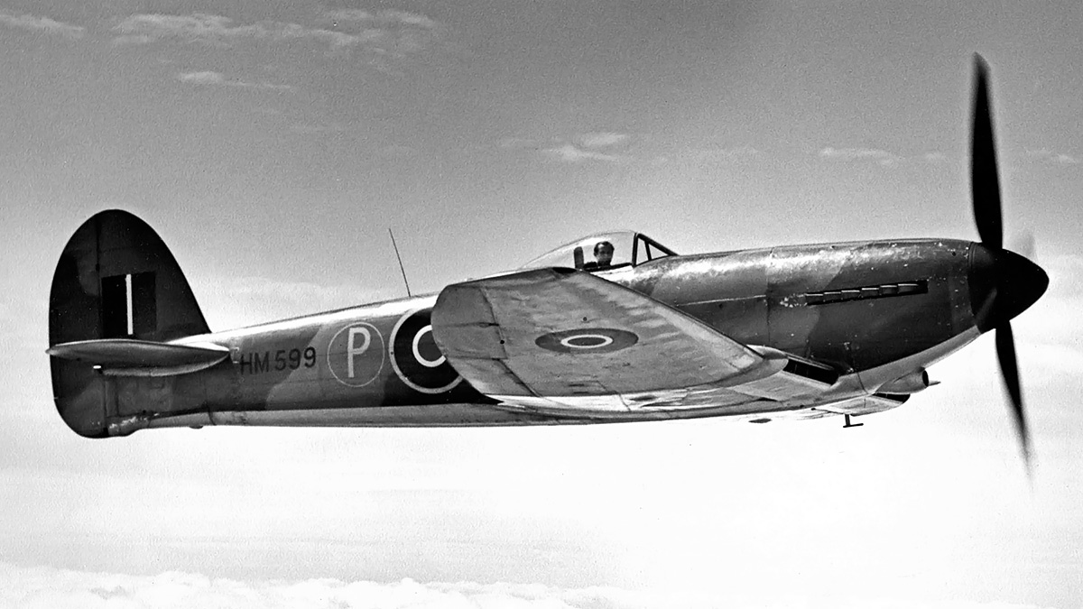
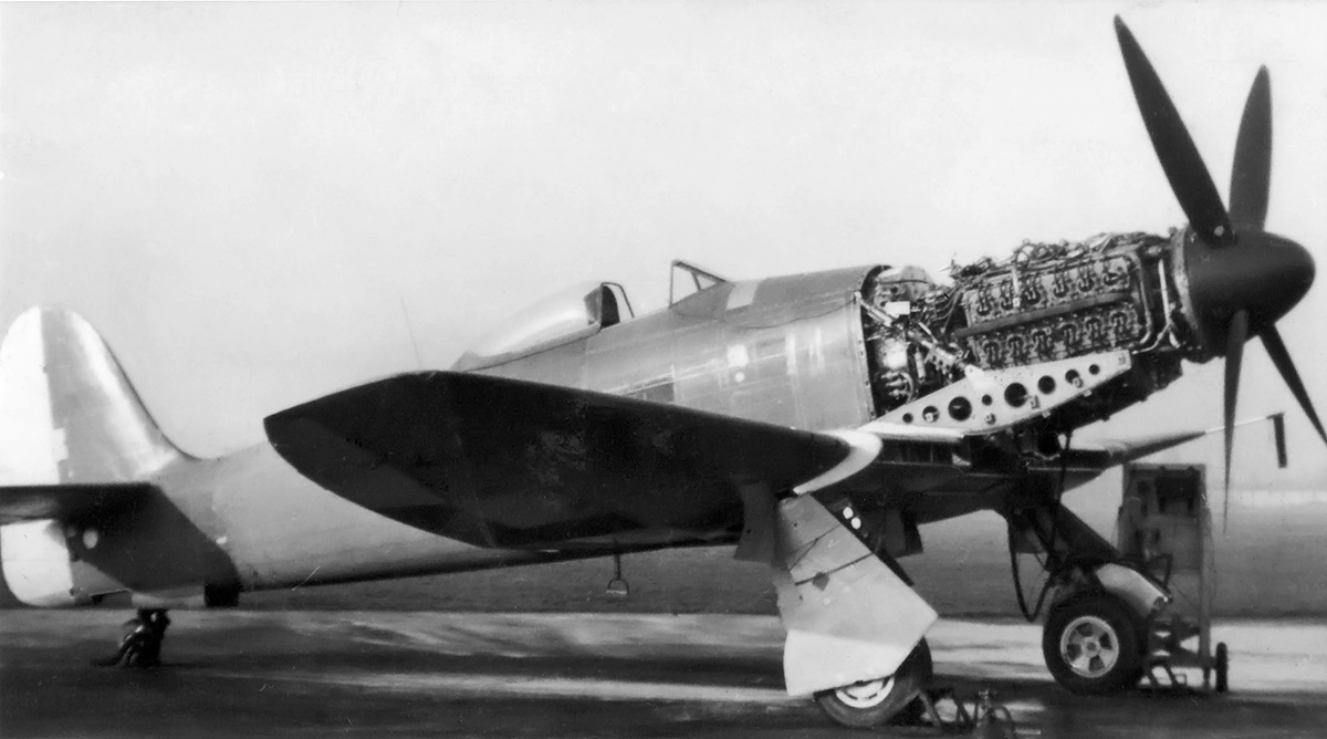
In the spring of 1943, some 1,250 engines had accumulated a total of 12,000 hours of testing and 40,000 hours of service use, and the Sabre’s service life was extended from 25 hours to 250 hours between major inspections. With Sabre reliability issues resolved and production resuming, development of the engine continued. The Sabre IV incorporated a two-barrel Hobson-RAE injection carburetor and a revised supercharger with a single-sided impeller. The supercharger clutches were updated and relocated from the extreme rear of the supercharger to between the supercharger and the engine. Revised gears turned the impeller at 4.68 times crankshaft speed in low gear and 5.83 times crankshaft speed in high gear. The Sabre IV produced 2,240 hp (1,670kW) at 4,000 rpm at 8,000 ft (2,438 m) with 9 psi (.62 bar) of boost. The engine was selected for the Tempest I, the prototype of which was initially ordered on 18 November 1941, followed by an order for 400 production aircraft in August 1942. The Tempest I featured a streamlined nose and its radiator and oil cooler were installed in the wing’s leading edge. The prototype Tempest I (HM599) was first flown on 24 February 1943, piloted by Lucas, and would go on to record a speed of 472 mph (760 km/h) at 18,000 ft (5,486 m) in September 1943. However, delays and development issues with the Sabre IV engine led to the Tempest I order being converted to Sabre IIA and IIB-powered Tempest Vs.
The Sabre IIA (E115) was a refinement of the Sabre II and had been developed in mid-1943. The engine had a modified oil system and used dynamically-balanced crankshafts. The Sabre IIA had a takeoff rating of 1,995 hp (1,488 kW) at 3,750 rpm with 7 psi (.48 bar) of boost. At 3,750 rpm and 9 psi (.62 bar) of boost, the engine had a military rating of 2,235 hp (1,667 kW) at 2,500 ft (762 m) and 1,880 hp (1,402 m) at 15,250 ft (4,648 m). At 3,700 rpm and 7 psi (.48 bar) of boost, the engine had a normal rating of 2,065 hp (1,540 kW) at 4,750 ft (1,448 m) and 1,735 hp (1,294 kW) at 17,000 ft (5,182 m). Fuel consumption at cruise power was .46 lb/hp/hr (280 g/kW/h). Starting around August 1943, Sabre IIA engines were incorporated into production Typhoon IB and Tempest V Series I aircraft.
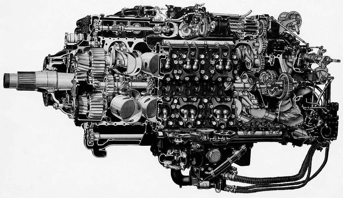
Cutaway drawing of a Sabre VA illustrating the engine’s propeller reduction gears and sleeve-valve drive. Note the upper and lower accessory drives, the slight fore-and-aft angling of the spark plugs, and the single-sided supercharger impeller. (Napier/NPHT/IMechE images)
In 1944, prototypes of the Sabre IIB (E107A) became available. Compared to the Sabre IIA, the IIB used a different carburetor, had a modified boost controller, and was cleared for additional engine speed. The Sabre IIB had a takeoff rating of 2,010 hp (1,499 kW) at 3,850 rpm with 7 psi (.48 bar) of boost. At 3,850 rpm with 11 psi (.76 bar) of boost, the engine had a military rating of 2,400 hp (1,790 kW) at sea level, 2,615 hp (1,950 kW) at 2,500 ft (762 m), and 2,045 hp (1,525 kW) at 13,750 ft (4,191 m). The Sabre IIB had the same normal rating as the IIA. The engine was used in later Typhoon IBs and was the main Sabre version to power the Tempest V Series II.
The Sabre IIC (E107B) was a similar to the IIB but with new supercharger gears. The impeller turned at 4.73 times crankshaft speed in low gear and at 6.26 times crankshaft speed in high gear. The engine had a takeoff rating of 2,065 hp (1,540 kW) at 3,850 rpm. At the same engine speed and with 11 psi (.76 bar) of boost, the military power rating was 2,400 hp (1,790 kW) at 2,000 ft (610 m) and 2,045 hp (1,525 kW) at 13,750 ft (4,191 m). The Sabre IIC was used in some late production examples of the Tempest V, including those converted as target tugs in 1948.
The Sabre V (E107C) was developed from the IV with an updated carburetor. Linkages were incorporated to allow one lever to control the engine’s throttle and the propeller’s pitch along with automatic boost and mixture control, but this system could be overridden by the pilot. The spark plugs were repositioned, although it is not clear if this change was made on the Sabre V or the Sabre VA engine. Rather than being parallel, as in earlier Sabre engines, the electrode of the front spark plug was angled forward, and the electrode of the rear spark plug was angled back. The engine produced 2,420 hp (1,805 kW) at 3,750 rpm at 4,250 ft (1,295 m) with 15 psi (1.0 bar) of boost. The Sabre V was tested in the Tempest I, and the combination was first flown on 8 February 1944 by Bill Humble. On 12 February, an order for 700 Sabre V-powered Tempest Is was issued. This order was later reduced to 300 examples, and then converted to the Sabre V-powered Tempest VI in May. The prototype Tempest VI (HM595 again) made its first flight on 9 May 1944, piloted by Humble. Cooling the more powerful engine in warmer climates required modifications to be incorporated into the Tempest VI, including a larger chin radiator and a secondary oil cooler in the wing. Carburetor inlets were also relocated to the wing’s leading edge. Otherwise, the aircraft was similar to the Tempest V.
A Tempest V Series I (top) and Tempest VI (bottom). The Tempest V Series I had Hispano Mk II cannons with long barrels that protruded from the wing’s leading edge. The Tempest V Series II and other Tempests had Hispano Mk V cannons with short barrels. The Sabre VA-powered Tempest VI (bottom) has an enlarged chin radiator, an oil cooler in the wing, and carburetor inlets in both wing roots.
The Sabre VA was essentially the production version of the Sabre V. The Sabre VA had a takeoff rating of 2,300 hp (1,715 kW) at 3,850 rpm with 12 psi (.83 bar) of boost. The engine’s military rating at 3,850 rpm with 15 psi (1.0 bar) of boost was 2,600 hp (1,939 kW) at 2,500 ft (762 m) and 2,300 hp (1,715 kW) at 13,750 ft (4,191 m). At 3,650 rpm, the Sabre VA had a normal rating of 2,165 hp (1,614 kW) at 6,750 ft (2,057 m) and 1,930 hp (1,439 kW) at 18,000 ft (5,486 m). Cruise power at 3,250 rpm was 1,715 hp (1,279 kW) at 6,750 ft (2,057 m) and 1,565 hp (1,167 kW) at 14,250 ft (4,343 m). Fuel consumption at cruise power was .50 lb/hp/hr (304 g/kW/h). The engine was 82.2 in (2.10 m) long, 40.0 in (1.02 m) wide, and 46.0 in (1.17 m) tall. The Sabre VA weighed 2,500 lb (1,134 kg). Starting around March 1946, the engine was the powerplant for production Tempest VI aircraft.
The Sabre VI was the same engine as the Sabre VA, but it incorporated an annular nose radiator and provisions for a cooling fan, all packaged in a tight-fitting cowling. The cooling fan rotated clockwise, the opposite direction from the propeller. The intent of the engine and cooling system combination was to produce a complete low-drag installation package that would cool the engine sufficiently for use in tropical climates. The radiator incorporated cooling elements for both engine coolant and oil.
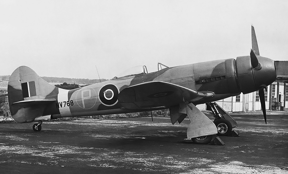
The Sabre VI incorporated an annular radiator and provisions for an engine-driven cooling fan. Tempest V NV768 was used to test a number of different spinner and annular radiator cowling configurations with the Sabre VI. The aircraft is seen here with a large ducted spinner. The configuration slightly improved NV768’s performance over that of a standard Tempest. (Napier/NPHT/IMechE image)
Napier and Hawker experimented with annular radiators using various Sabre IIB engines installed on a Typhoon IB (R8694) and a Tempest V (EJ518). In early 1945, the Sabre VI with an annular radiator was test flown on a Tempest V (NV768). Numerous changes to the annular radiator and its cowling eventually led to the development of a ducted spinner, which was installed on NV768. The aircraft continued to test annular radiators through 1948. While the annular radiator added 180 lb (82 kg), it created only a third of the drag compared to the chin radiator, decreased the aircraft’s overall drag by almost nine percent, and improved the Tempest’s top speed by 12 mph (19 km/h). The annular radiator’s durability was inadvertently tested on 18 December 1944 when EJ518 made a forced, gear-up landing after a hydraulic failure. The annular radiator was undamaged and later installed on NV768. The chin radiator was typically destroyed during a gear-up landing.
Two Sabre VI engines, each with an annular radiator and a cooling fan, were installed on a Vickers Warwick C Mk III (HG248) twin-engine transport. With the Sabre engines, the Warwick’s top speed was limited to 300 mph (483 km/h) due to its fabric covering. This was still about 75 mph (121 km/h) faster than the aircraft’s original design speed. Most of the annular radiator testing was conducted at Napier’s Flight Development Establishment at Luton. While some of the ducted spinner research was applied to the Napier Naiad turboprop, none of the work was applied to production piston engines.
A Vickers Warwick C Mk III (HG248) was used to test the installation of the Sabre VI engine with an annular radiator and an engine-driven cooling fan. Note that the fan rotates in the opposite direction from the propeller and that the lower cowling folds down level to be used as a work platform. The rear four exhaust ejectors were replaced with elongated stacks to prevent excessive heat build-up on the wing’s leading edge. (Napier/NPHT/IMechE image)
The Sabre VII carried the Napier designation E121 and was essentially a VA engine strengthened to endure higher outputs. The engine was fitted with water/methanol (anti-detonant) injection that sprayed into the supercharger via an annular manifold. The mixture used was 40 percent water and 60 percent methanol. The water/methanol injection lowered the engine’s tendency toward detonation and allowed for more power to be produced. The supercharger housing was reworked for the water/methanol injection, and the cylinder heads were modified to accommodate two compression rings. Individual ejector exhaust stacks were fitted, replacing the two-into-one stacks previously used on most Sabre engines.
Initially, the Sabre VII had a takeoff rating of 3,000 hp (2,237 kW) at 3,850 rpm with water/methanol injection and 17.25 psi (1.19 bar) of boost. This was later increased to 3,500 hp (2,610 kW) at the same rpm with 20 psi (1.38 bar) of boost. The engine’s military rating at 3,850 rpm with 17.25 psi (1.19 bar) of boost and water/methanol injection was 3,055 hp (2,278 kW) at 2,500 ft (762 m) and 2,820 hp (2,103 kW) at 12,500 ft (3,810 m). The water/methanol injection flow rate was 76 US gph (66 Imp gph / 300 L/h) at takeoff, 78 US gph (65 Imp gph / 295 L/h) at military power in low supercharger, and 122 US gph (102 Imp gph / 464 L/h) at military power with high supercharger. The water/methanol flow rates corresponded to 30 percent of the fuel flow at low supercharger and 45 percent of the fuel flow at high supercharger. The Sabre VII’s fuel flow was 284 US gph (235 Imp gph / 1,068 L/h) at takeoff, 287 US gph (239 Imp gph / 1,087 L/h) at military power in low supercharger, and 289 US gph (241 Imp gph / 1,096 L/h) at military power with high supercharger. At 3,700 rpm and 10.5 psi (.73 bar) of boost, the Sabre VII had a normal rating of 2,235 hp (1,667 kW) at 8,500 ft (2,591 m) and 1,975 hp (1,473 kW) at 18,250 ft (5,563 m). Cruise power at 3,250 rpm was 1,750 hp (1,305 kW) at 8,500 ft (2,591 m) for a fuel consumption of .45 lb/hp/hr (274 g/kW/h), and 1,600 hp (1,193 kW) at 17,000 ft (5,182 m) for a fuel consumption of .51 lb/hp/hr (310 g/kW/h). The engine was 83.0 in (2.11 m) long, 40.0 in (1.02 m) wide, and 47.2 in (1.20 m) tall. The Sabre VII weighed 2,540 lb (1,152 kg). Some sources state that a Sabre VII engine achieved an output of 4,000 hp (2,983 kW) and was run at 3,750 hp (2,796 kW) for a prolonged period without issues during testing.
A Sabre VII with its revised supercharger housing that accommodated water/methanol injection. The injection controller is mounted just above the supercharger housing. The Sabre VII ultimately produced 3,500 hp (2,610 kW) at 3,850 rpm with 20 psi (1.38 bar) of boost. (Napier/NPHT/IMechE image)
The Sabre VII was intended to power the Hawker Fury Mk I, of which 200 were ordered in August 1944. Shifting priorities at the end of the war all but cancelled the aircraft, and only two prototypes were built. The first prototype (LA610) made its initial Sabre VII-powered flight on 3 April 1946. This aircraft would go on to record a speed of 483 mph (777 km/h) at 18,500 ft (5,639 m) and 422 mph (679 km/h) at sea level. The Sabre VII was also test-flown on a Tempest V or VI in mid-1946, but additional details have not been found. This aircraft had the larger radiator and wing root carburetor inlets of the Tempest VI, but it did not have the additional oil cooler in the wing.
The Sabre VIII carried the Napier designation E122 and was based on the Sabre VII. The engine incorporated contra-rotating propellers and a two-stage supercharger. Four aftercoolers were to be installed—one on each induction runner leading from the supercharger housing to the intake manifold attached to the cylinder bank. Although some sources say the Sabre VIII was built, it appears to have remained an unbuilt project. The engine was forecasted to have a military rating of 3,350 hp (2,498 kW) and be capable of 25 psi (1.72 bar) of boost.
The Napier Sabre VII engine installed in the nearly-complete Hawker Fury Mk I prototype. The aircraft and engine combination created a fast and elegant fighter. Note the leading edge wing radiators. (Napier/NPHT/IMechE image)
Production of the Sabre was halted shortly after the end of World War II with approximately 5,000 engines produced. Starting in October 1939, Napier worked to establish a shadow factory in Liverpool to produce Sabre engines. The first engine, a Sabre II, was completed at this factory in February 1942. The Liverpool site manufactured around 3,500 II, IIA, IIB, and VA engines, with the remaining 1,500 engines, including all prototypes, coming from Napier’s Acton works. With Sabre development at an end, Napier focused on their next aircraft engine, the two-stroke diesel/turbine compounded Nomad.
A number of engine designs based on the Sabre were considered, but most stayed as projects, and none progressed beyond cylinder testing. The E109 of 1939 was half of a Sabre, with 12-cylinders and a single crankshaft. It would have displaced 1,119 cu in (18.34 L). The E113 of 1940 was a fuel-injected, two-stroke, uniflow, Sabre-type test engine intended for increased engine speed and boost. The design concept originated with Harry Ricardo, and a two-cylinder test engine was built in 1942. Reportedly, the test engine was so loud that people on the street had to cover their ears as they passed by Napier’s works in Acton. The E120 of 1942 was a 32-cylinder Sabre consisting of four banks of eight cylinders. It would have displaced 2,985 cu in (48.91 L). The E123 of 1943 was a complete 24-cylinder, fuel-injected, two-stroke Sabre based on the E113 test engine. It had a forecasted output of 4,000 hp (2,983 kW) but was never built.
Although the Sabre was proposed for many projects that never left the drawing board and powered a few prototypes, the engine’s main applications were the 109 Typhoon IAs, 3,208 Typhoon IBs, 801 Tempest Vs, and 142 Tempest VIs produced during World War II. After the initial production difficulties, which were quite severe, the engine served with distinction. The Sabre could be difficult to start, and it was advisable to use a remote heater to pre-heat the coolant and oil in cold temperatures. Sleeve trouble came back with Typhoons stationed around Normandy, France in the summer of 1944. Fine dust particles from the soil were getting into the engines and causing excessive sleeve wear. A momentum air filter developed by Napier cured the trouble. The filter was designed and test flown the same day of its original request, and all the Typhoons in France were fitted with a filter within a week. Production of the Sabre was an expensive affair, with each horsepower costing four to five times that of the Rolls-Royce Merlin. However, Typhoons and Tempests played an important role in attacking German forces on the ground and countering V-1 flying bombs. Around a dozen Sabre engines survive and are on display in museums or held in private collections. As of 2020, there are no running Sabre engines, but efforts are underway to create running examples to power Typhoon and Tempest aircraft under restoration.
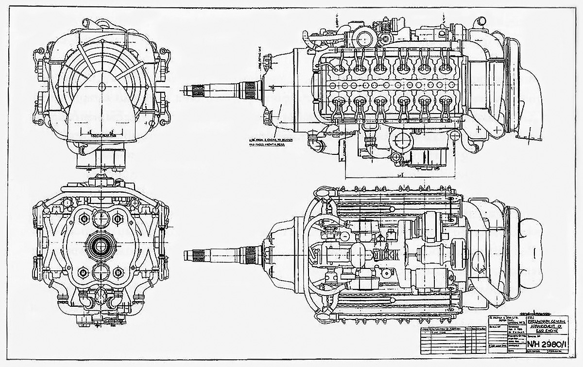
General arrangement drawing of the unbuilt Sabre VIII (E122). The engine featured a two-stage supercharger and contra-rotating propellers. It was forecasted to produce 3,350 hp (2,498 kW).
Sources:
– Major Piston Aero Engines of World War II by Victor Bingham (2001)
– Allied Aircraft Piston Engines of World War II by Graham White (1995)
– Aircraft Engines Volume Two by A. W. Judge (1947)
– By Precision Into Power by Alan Vessey (2007)
– An Account of Partnership – Industry, Government and the Aero Engine by George Bulman and edited by Mike Neale (2002)
– I Kept no Diary by F. R. (Rod) Banks (1978)
– Boxkite to Jet — the remarkable career of Frank B Halford by Douglas R Taylor (1999)
– The Napier Way by Bryan ‘Bob’ Boyle (2000)
– The Hawker Typhoon and Tempest by Francis K. Mason (1988)
– Hawker Typhoon, Tempest and Sea Fury by Kev Darling (2003)
– Tempest: Hawker’s Outstanding Piston-Engined Fighter by Tony Buttler (2011)
– Hawker Aircraft since 1920 by Francis K. Mason (1991)
– Blackburn Aircraft since 1909 by A. J. Jackson (1968/1989)
– Aircraft Engines of the World 1945 by Paul H. Wilkinson (1945)
– Aircraft Engines of the World 1946 by Paul H. Wilkinson (1946)
– Aircraft Engines of the World 1949 by Paul H. Wilkinson (1949)
– “The Napier Sabre Engine Parts 1–3” by J. A. Oates, Aircraft Production Volume 6, Numbers 66–68 (April–June 1944) via The Aircraft Engine Historical Society
– “Napier Sabre II” by F. C. Sheffield, Flight (23 March 1944)
– “Napier Sabre VII” Flight (22 November 1945)
– “Napier Flight Development” Flight (25 July 1946)
– Jane’s All the World’s Aircraft 1945/46 by Leonard Bridgman (1946)
– Jane’s All the World’s Aircraft 1947 by Leonard Bridgman (1947)
– Jane’s All the World’s Aircraft 1948 by Leonard Bridgman (1948)

Dear Mr Pierce,
Thank you for this superb article on the Napier Sabre. What an engine and let’s hope someone gets one running.
Regards,
Maurie Copsey
AUSTRALIA
Hello Bill;
Another fascinating article on what has to be one of the most interesting aircraft engines ever designed. You’ve outdone yourself – a very impressive essay made even better with astounding photographs, particularly of the engine during assembly.
In 1984 I stood next to the Sabre engine on display at the RAF Museum Hendon ( now London I think ) for some time, amazed at the complexity of it. In 2016 I was at Burlen Fuel Systems in Salisbury and had a brief look at the SU carburetor used on the early versions of the Sabre.
I am old enough now that I’ll have to read the article several times to glean everything from it but I look forward to that! Many thanks,
Rhys Kent
Another great slice of mechanical history pie from Bill Pearce, so thanks for that. OK, I had to look up “austenitic”.
Hello Maurie, Rhys, and Tom – Thank you all for the kind words. This one was a long time coming.
Hi William – you can add me to the list of people who enjoyed this article. I’ve long been a fan of the Sabre and hope to be able to hear/see one in action when the project to restore a Typhoon to flying condition is successful (see https://hawkertyphoon.com/ for details).
I worked in the Napier Liverpool works in the 1960’s on DELTIC production.
There were a number of engineers there who had worked on the Saber production.
Napiers were good at making complex designs work and put in a great effort in making the complex Saber a success which helper win the war.
It was not a user friendly engine but powered the Hawker Typhoon to great success in the latter stages of the war and is fondly remembered in France for destroying German tanks and anything that moved such as trains , troops etc.
Sadly when the war ended the Typhoons were flown back to their bases and scrapped.
Not a single Typhoon was preserved in flying condition and now there are preservation groups valiantly attempting to build an air worthy Typhoon with a Saber engine.
I shall look forward to hearing and seeing a Typhoon in the air.
Hello,
I don’t suppose you knew my father, Leonard Calder? He worked at Napier in Acton, I think the Sabre was part of his apprenticeship there, then he was transferred to Liverppol in around 1949. He worked for the English Electric (possibly overlapping with Napier) then for AC Delco. The timeline is probably too early, but you never know.
Thanks
Martin Calder
This was a fascinating read, thanks very much. I do have one nit to pick, however; the water/methanol injection rates are reported in US and British gallon/hour, but the liter volume is in liters/minute. Doing the math shows the number is correct, but the time period probably should be L/h.
Hello Steve – Glad you liked the article. Thank you for pointing out the wrong unit. I have made the corrections.
Hello William,
A really good read, I have always been fascinated by this engine, its flaws add to the interest. Of all the other manufacturers, only Junkers it this interesting. And of course, Frank Halford was a great engineer with an astonishing career,
As you may already know, there is contention about the final output power of the Sabre. Setright made some unrealistic claims and this just adds fuel to the fire of the naysayers Would it be possible for you to narrow down the sources you used for the performance figures of the Mk VII? Unfortunately, I do not have access to much of the material you cite in the references at the bottom of this article, so narrowing it down would be of great benefit to me.
Best Regards,
Rob
Hello Rob,
I am glad you liked the article. I assume that the interest/contention lies with the Sabre VII’s higher output figures. The 3,055 hp (or 3,050 hp) figure is pretty widely reported, so I will skip that one.
Aircraft Engines of the World 1949 by Paul H. Wilkinson (1949) on page 245 gives the Sabre VII takeoff rating of 3,500 hp at 3,850 rpm with 20 psi of boost. The 1949 edition was inadvertently left off the article’s original source list, but has now been added.
Major Piston Aero Engines of World War II by Victor Bingham (2001) on page 96 states: “…on test a Sabre VII was run at 3,750 hp for 175 hours non-stop.” Personally, I’m a bit doubtful of these numbers, but I included them in a far-less definitive fashion with “some sources state” and “a prolonged period.” Also on page 96, the book has a pretty good breakdown of the Sabre VII’s normal outputs.
Allied Aircraft Piston Engines of World War II by Graham White (1995) on page 172 states, referring to the Sabre VII: “…a phenomenal 3500 hp was achieved at 3850 rpm with 70.6 in Hg manifold pressure. Finally, Napier test-ran a Sabre at 4000 hp with ADI.” The 3,500 hp achieved at 3,850 rpm with 70.6 in Hg of boost match the Wilkinson values, but I don’t know the origins of the 4,000 hp. I thought the 4,000 hp output was reported in another non-Setright source, but I could not find it. However, like the Bingham values, the 4,000 hp falls under the “some sources state” heading.
Aircraft Engines Volume Two by A. W. Judge (1947) on page 477 states: “… Series VII… 3,655 h.p. maximum power (combat rating) at 3,850 R.P.M at 2,250 ft. altitude with moderate supercharge.” I include this source as an example that I was not just blindingly including numbers. I believe the “3,655” is a mistake and it should read “3,055.”
I did not use Setright as a source as I have always felt the 5,500 hp at 4,200 rpm with 45 psi of boost Sabre claim was too much. Maybe a single- or twin-cylinder test engine ran at a pace such that when scaled up to a full engine, those numbers were the mathematical result. I’d like to believe it, but I have not seen anything to support those numbers.
In summary, none of the numbers come from any official report that I am aware of. If the reported outputs were achieved, it seems they were done in the late 1940s, when many were focusing on other forms of propulsion. Anyway, I hope the above was helpful.
Best regards,
William
I am sorry it took me almost a year to reply to you. I appreciate the extra detail you provided. In many ways it confirmed my suspicions
I remember seeing an advertisement in Flight magazine (from the archive while it was still available) by Napier where they quote the Sabre’s power output as up to 3500HP, i do not think they specified what standard that power was measured to, normal, military, etc.. I can think of no reason why Napier would falsely claim the figure, what purpose would it serve? I think we can give 3500hp considerable credence.
I did some crude calculations and baring some other problems (the sometimes cited sleeve valve barreling), contemporary BMEPs and maximum piston velocities would get the engine to 4000hp – just. I do not hold out a great deal of hope that this was reached in any meaningful way.
Speculation on Setwright’s 5500hp figure is fun, I have speculated that someone may have told him this was the structural limit of the engine and he either misheard or misunderstood what was said, we will never know. I was trying to estimate the heat rejection of the engine if it was to produce that sort of power for any length of time, the mind boggles.
Similarly, I think that running the engine at 3750hp for 175 hours is more than a bit unlikely.
The saddest part of all this is just how little documentation for these British engines has survived. As far as I know, there are no complete engineering or production drawings for any mark of Napier Sabre, I have only seen a few drawings of the Sabre blocks of an early mark and the linkages of a late mark fuel system.
The sleeve barreling problem that RR had reportedly found was hearsay from surviving engineers who knew the engineer who did the tests. It is certain that at Hives’ RR if such a study was undertaken, a full report would have been written. That report appears to have not survived. One author seems to have relied quite a bit on German reports of captured engines, perhaps the German archives have more information on this engine than the British archives.
The Americans seem to have far better archives.
Do you intend on writing an article on the P&W liquid cooled sleeve valve H engines? I wonder what technical documentation, if any, survived the cancellation of those projects.
As always, a pleasure reading your articles, even for engines that had previously held little interest for me.
Regards,
Rob
Kimble McCutcheon has written an excellent book on the American sleeve valve engines. It was a trail of tears. https://www.amazon.com/gp/product/0971084785/ref=dbs_a_def_rwt_hsch_vapi_taft_p1_i0
Hello Rob – No worries on the reply timeframe; I know how I goes.
I feel the disappearance of the Flight archive is a tragedy. Not nearly as great of a tragedy as all the company archives that were discarded with a change in ownership or location, but still a tragedy. I hope that it can return someday.
I don’t recall seeing ads for a 3,500 hp Sabre. I know there were ads for 3,000 hp. For fun, here is a link to the Aviation Ancestry Database with 28 Napier Sabre ads. I searched for the 3,500 hp ad, but I could not find it. It would be interesting to see what date it was published.
I do not intend to write about the Pratt & Whitney H-engines for the reason Tom listed. Kim’s American Sleeve-Valve Aircraft Engines book is excellent and based on the info available in the archives. While what is in the archives is not complete, Kim puts it all together for a detailed look at the various engine programs.
Best regards,
William
Hi Rob, if you do search, there are Sabre documents spread far & wide, from within the Vickers collect at Brooklands Museum, with some able to be viewed online freely, such as on the IMECHE site,
like this one, with sealing pressure figures for Sabre rebuilds:
https://archivecat.imeche.org/records/NAP/6/5/42
Or this one for a crankshaft engineering drawing:
https://archivecat.imeche.org/records/NAP/6/5/29
Another thing per the (stillborn) US-connection with the Sabre was the potential for turbocharger equipped Typhoons (& perhaps the British hi-speed/unarmed ‘Super-Mosquito’ & its Hawker ‘sister’).
Hawker produced the drawings for G.E. turbo fitment in the thick wing section of the Typhoon, close to the engine (plans can be seen in the UK National Archive in Kew) & Napier ‘apparently’ tested the set-up at their Luton Flight-Research unit. Here below, is linked a Napier graph (per Calum Douglas) which depicts the effect of the ‘altitude compensation’ on power/height – which the USAAF was keen on.
Also, the UK Science Museum does list holding documents by Napier Works Engineer P.J. Wallace – pertaining to “…testing of N. Sabre…”,
along with their engine, which sadly, also seems to be a ‘sectioned’
Sabre VII, just like the IWM’s unit & the couple mentioned already.
Hope this helps with your upcoming itinerary, Rob.
Regards,
James
Hi William,
Full credit for your authoritative source checking.
Len Setright’s emotive/enthusiastic writing style
was rightly critiqued, but he did claim to have
transcribed the data points he used, directly
from Napier factory documents (- as had ‘Flight’).
It would seem that many of these Sabre-related
documents are now kept in the archives of the
British Institution of Mechanical Engineers.
https://www.imeche.org
I’m sure you must’ve also had doubts about a
recent book which gives a Sabre appraisal from
the ‘damned with faint praise’ – end of the spectrum,
viz: ‘The Secret Horsepower Race’ by Cal Douglas.
Douglas it would appear, could gain a more useful
understanding of engine design merits, and ‘power
to fly and fight’ fundamentals – by reading your articles,
especially given the misapprehensions he propounds.
A glaring example being his seemingly blithe acceptance
of exceptionally high piston speeds quoted in Jumo 213
projected power outputs from long stroke cylinders
accommodating very high rpm (Roy Fedden stated he
was ‘incredulous’ on 1st principles, about this claim).
Certainly as an F1 racecar engineer, Douglas would
do himself a service by learning about ‘approved for
flight-clearance power ratings, allowable power-
settings/time periods’, and volumetric efficacy of
sleeve valves at lower boost levels than poppets.
(He need only compare the boost-level/fuel grade
requirements at max BMEP outputs for the most
highly developed 36 litre Sabre VII and Griffon 130
with resulting power outputs – quoted in Wilkinson
– along with endurance & consumption at cruise).
He also fails to acknowledge that the Sabre was
flown hard by RAF Tempest units up to the mid `50s,
latterly providing realistic air-to-air gunnery training
for RAF jet-jockeys, (one remark made to a dubious
jet pilot was: ‘Make no mistake, without the target
drogue, those Tempests have no trouble giving
Vampires the runaround at low-level!’)
I have spent a bit of time going through my very disorganized collection of information. Further, I have been through the listings in the link you provided for the Sabre and quite a few others, most interesting. I have to admit that I can find no evidence for my recollection of the “up to 3500hp power rating” and must conclude hat “I must have been dreaming”, most likely I have conflated two different things – this, of course, is how these questionable claims start. I had a look around and can not find what I used as a basis for the 3500hp, it certainly was not the Nomad, either of them, nor any other Napier engine.
I am afraid we are left with the 3055hp takeoff with ADI figure as the highest power output from a “reliable” source.
That number was also in the book on Frank Halford, “Boxkite to Jet”, not a primary source so not really useful to this discussion.
One of the other engines that I am interested is the XB-4070 supercharged diesel barrel engine, I believe that one of these prototype engines still exists. This used the Michell tilting pad trust bearing to transmit the linear trust of the piston to the rotating “slant”. My interest in this is primarily via A.G.M.Michell, a remarkable man. The following is a link to a YouTube video on Michell:
His work on crankless engines starts just before 40minutes and the XB-4070 just after 47 minutes.
Again, thanks for your help and, of course, your articles.
Hello Bill,
I have Just watched a Kermit Weeks YouTube video of the current status of his Hawker Tempests. Richard Grace is in the video. There are quite a few errors in these videos. BUT, what i find astonishing is that Kermit now has two Napier Sabres.
One is identified as a Sabre V that appears to be a crate engine. Richard Grace says it is new, never flown through external inspection, I am unconvinced. However, i could easily see it as an overhauled engine. In any case, i am hopeful that we may once again hear a Sabre running at power, even if it is on the ground.
The other is identified as a Sabre III, which if correct would (I assume) make it a very rare engine.
This raises the big question, just how many Sabres exist, what Marks are thy, what condition are they in? Do you know if there is a database that details the remaining Sabres.
Rob Nicholson
Per Rob’s enquiry about still-extant Sabres, there has been a list made, & IIRC – sadly, most are in a damaged state, via crash recovery, & by ‘section for display’.
(If Kermit Weeks does have a Mk III Sabre, it does have a surviving twin – of the 25 built for Naval aviation use – & it is on display at the RN Fleet Air Arm Museum).
In a Norman Franks book (I forget the title) he includes the comments of an ex-RAF ‘engine-basher’ (fitter) who describes the unceremonious dumping of new/surplus to requirements (still in crates/inhibited) Sabre VA’s off the end of the British military pier at Khartoum Sudan, into the river Nile – at the end of Tempest service there, 70 odd years ago. (Might be a bit fraught to mount a salvage expedition there, currently, though).
Certainly, the RAF’s use of its Sabre-powered Tempests – for about a decade – of hard-flying duty post-war, both in harsh Middle Eastern-African conditions, & to provide training for its ‘jet-jockeys’ – towing air-to-air targets at realistic speeds, belies the ‘perceived trope’ held by many – of the Sabre being a ‘tender’ device requiring unfeasible levels of ‘fettling’ in service, & thus only a wartime expedient.
Similarly, any 24 cylinder mill is per se a ‘complex’ unit – but that does not mean the Sabre was therefore ‘needlessly complicated’ – in a pejorative sense, as such.
(Do a core engine – parts count for a Porsche 911 flat six – is it less than 1/4 the number used by the Sabre – for the same functions? I’d doubt it.)
Mike Nixon has rebuilt many WW2 era aero-engines (including Bristol sleeve-valve units), & has stated that given the specific tools/manuals – a Sabre presents as a straightforward proposition for overhaul likewise.
Perhaps Rob, you could direct Richard Grace to this splendid site, so that he too can benefit from Bill’s well written/researched articles, just as we have?
Lastly, as to Len Setright’s ‘bold claim’ of “5,500hp on test” – given he noted it was apparently performed sans cooling/supercharge/fuel limitations – then it is feasible, on the same basis as the ‘flash reading’ power outputs obtained from Allison V-1710 & R/R V12s used in ‘tractor-pulling’/ ‘unlimited hydroplanes’, etc.
Hello James,
I have gone back over the video and Richard Grace definitely says a Napier Sabre Mk III, they show the identification plate but I can’t make out what Mark it is from that glimpse.
To tell the truth I don’t trust much from the video, some of the things that are said by Richard Grace (and to a lesser extent Kermit) are very strange and some are very wrong. At one stage Richard Grace says they put the engine in airliners and trains!! there is also some sillyness about trading the (possible) MK III for the sectioned one in the Science Museum so that they get spare parts of the MkV. I haven’t seen the Sabre in the Science Museum (next year, I am hopefully going to spend about 4 months in Britain, 3.5 of those months in museums) but from photos it has an outboard supercharger clutch and a carby, so it is probably just as old and incompatible to the Mk V as the putative MkIII.
Apparently he has an engine guy back in england that he has run this past so perhaps we are talking the about the same person.
The thing that worries me most about Sabre restorations is the level of existing documentation for the engine. AFAIK there is no complete set of plans for any mark of the engine, indeed there are very few engineering drawings at all.
The devil is in the detail. I assume there is no one alive who worked on these engines. Are there even extant copies of the manuals for the Sabre and if so which mark? Does anyone know the factory torque settings? You can calculate them, but there is going to be a lot of assumptions involved.
If you had an infinite supply of money, you could get one of the sectioned Mk VIIs (the Canadians have two!!) and using modern scanning techniques recreate a set of engineering/manufacturing plans. You could build new engines, there is nothing problematic, it is all reasonaably straight forward EXCEPT casting the sleeves, do we even know the detailed, complete, sleeve production process. The rest of the castings and all the machining (including the sleeves) can be done today with tolerances that Napier could only dream of back in the nineteen forties.
Of course, you would have to stick to the engine design as used in the nineteen fourties, you can not “improve” the engine without exhaustive tests.
I don’t believe the Setright claim, to get that level of power would require a BMEP or a rev limit well outside of what was possible at the time.
More later on.
Regards,
Rob
Hi Rob, I have to agree, the video with Richard Grace expounding the limits of his knowledge on the subject of the Sabre* – was a tad alarming/dispiriting!
It may be worth asking to view the Sabre test documentation held by the Science Museum, when you visit to see their Sabre engine – their archive lists such items.
Rolls-Royce may well have hold Sabre data, (they hastily shut down the Napier Aero-engine Works, when given the opportunity, in the 1960s) yet sadly, don’t offer any access to their archive stacks.
A visit to Kew to peruse Air Ministry ‘Type Test’ reports on the Sabre maybe of interest, & where are the Hawker Test-Flight reports on Sabre-Fury VP 207 flown with the final Sabre VII (type-tested @ +20lbs boost on ADI) up through 1948?
Check: https://www.enginehistory.org/index.php if you scroll down you’ll see listed entries for Napier Sabre overhaul, & the required tool kit.
With the Canadians, one of theirs was formerly on display at the RNZAF Museum, prior to it being garishly decorated for show at an Art Gallery in New Zealand! Perhaps they’ve ‘got lucky’ & the two they have – were ‘dissected’ non-identically?
Likely the Smithsonian Museum has documentation in store, along with their Sabre engine, since Sabre manufacture by Chrysler Corp was intended, for use in Bell Corp built Typhoons – prior to this plan being stymied by the #1 priority – the huge B-29 program – with Chrysler responsible for Wright R-3350 production (& Bell still having a keen customer in Stalin, for otherwise unwanted P-39s).
As for the ‘5,500hp’ Sabre test noted by Len Setright, well he did state that was carried out in the well-equipped English-Electric dyno-cell, & absent the limits that aircraft mounted mills had to accept (viz: cooling capability/regulation TBO power settings/fuel use/supercharger boost & available propellor power- absorption), while the dyno-lab was providing ideal parametrics for oil/coolant control, plus any amount of boost & high-speed intake ram air – all from external sources.
If you check the Napier-Railton Land Speed Record car driven to ~400mph by owner/driver John Cobb, (via article also here on Bill’s fabulous site) you’ll see how an earlier Napier engine, the Lion – was developed from a ~400hp RAF service-use rating through a race-development program to four times that power by use of boost increases from supercharging and exotic fuel; ice-water cooling & raising engine internal strength to allow raised gas-flow/rpm levels.
Another analogy could be seen in the development of the Chrysler Hemi V8, from a NASCAR endurance racing engine of ~500hp, to a drag-race mill giving many times that output, for a ‘sprint’ period of running, with just a few minutes of TBO.
*Napier did propose a marine-use Sabre for fast patrol boats, but went to the Deltic 2-stroke CI engine instead, at British Admiralty request – for diesel power.
Regards,
James.