Monthly Archives: May 2018

Lycoming XR-7755-3 side

Lycoming XR-7755 36-Cylinder Aircraft Engine

By William Pearce

Since 1933, the Lycoming Division of the Aviation Manufacturing Corporation had worked to create a high-power engine for the United States Armed Forces. Its first attempt was the 1,200 hp (895 kW), 12-cylinder O-1230, which was outclassed by the time it first flew in 1940. Lycoming’s second attempt was the 2,300 hp (1,715 kW), 24-cylinder XH-2470. The engine had shown some promise, but its performance was eclipsed by other engines when the XH-2470 was first flown in 1943. Lycoming set out to design an engine that was more powerful than any other and that would meet the power needs of future large aircraft.

Lycoming XR-7755-3 side

The Lycoming XR-7755 was the most powerful aircraft engine in the world when it was built. The XR-7755 was the culmination of Lycoming’s experience with radial and liquid-cooled engines. Conceived in 1943, such a large engine was not needed by the time it first ran in 1946.

In mid-1943, Lycoming engaged in talks with personnel from the US Army Air Force (AAF) at Wright Field, Ohio. Different sources list the involvement of the Air Materiel Command, Air Technical Service Command, and the Power Plant Lab. By December 1943, the engine concept had been solidified as a very large displacement, high-compression, liquid-cooled engine designed for optimum fuel economy and intended to power the next generation of very large aircraft. Lycoming’s experimental engine was designated XR-7755 and given the “Materiel, Experimental” code MX-434.

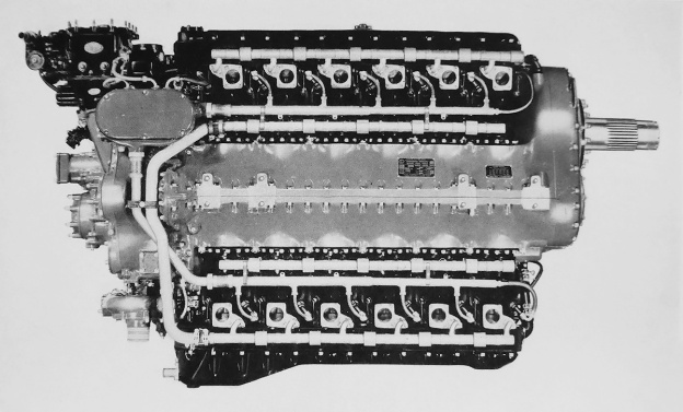
Clarence Wiegman headed the Lycoming XR-7755 design team. The engine consisted of nine banks of four inline cylinders positioned radially with 40-degrees of separation around a forged steel crankcase. This formed a 36-cylinder inline radial engine. The crankcase was made up of five sections, each split vertically through the cylinders. The crankcase sections were secured together by nine bolts that extended the length of the case. The individual steel cylinders each had their own water jacket. Each bank of four cylinders shared a common cast aluminum cylinder head. Each four-cylinder bank was secured to the crankcase by 16 long studs that passed through the cylinder head.

Lycoming XR-7755-3 stand

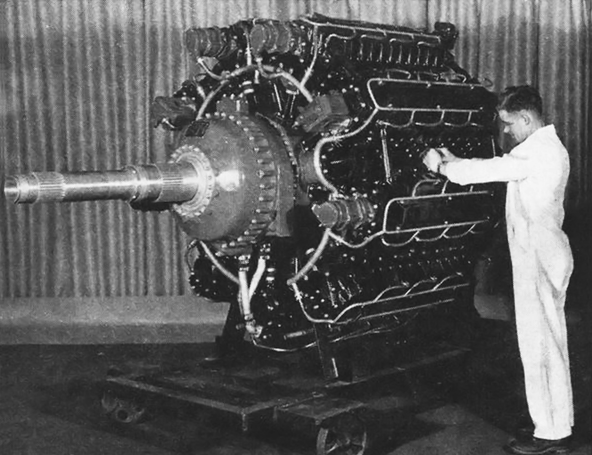
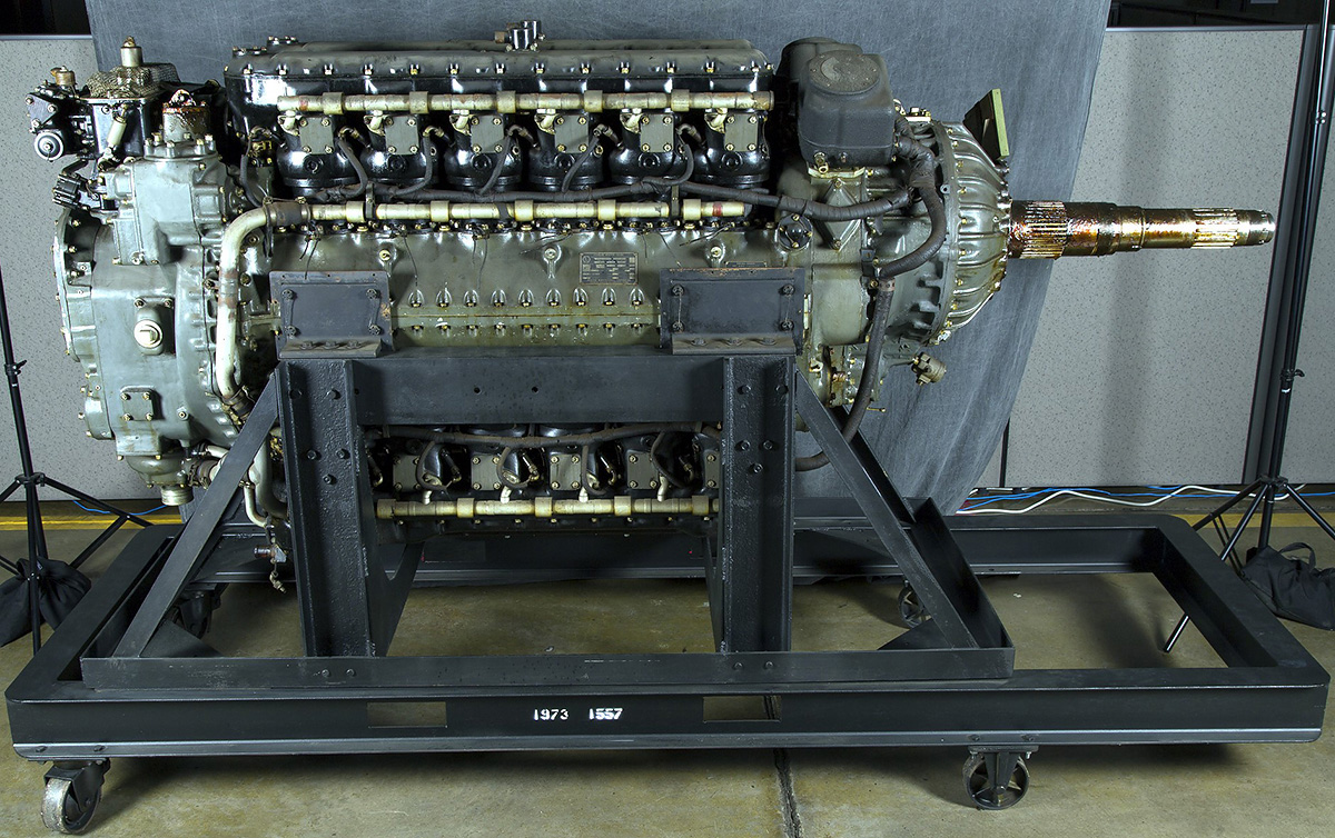
The worker gives some perspective to the XR-7755’s large size. However, the engine’s three-ton (2.74 t) weight is hard to imagine. The engine’s two magnetos and four distributors are visible on the front of the cylinder banks.

Each cylinder had one intake and one exhaust valve. Both valves were sodium cooled, with a hollow stem for the intake valve and a hollow stem and head for the exhaust valve. The valves for each bank of cylinders were actuated by a single overhead camshaft, driven via a vertical shaft at the front of the engine. Each camshaft had two sets of lobes for different valve timing—one lobe set was optimized for power and the other set for economic cruise. The camshafts shifted axially to engage the desired set of lobes. When the camshaft was shifted, the spark plug timing was automatically changed. Ignition was provided by two magnetos and four distributors. Each unit was camshaft-driven and mounted to the front of a separate cylinder bank. The spark plug leads passed through the valve covers and to the spark plugs, which were positioned in opposite corners of each cylinder.

Lycoming XR-7755-1 test stand

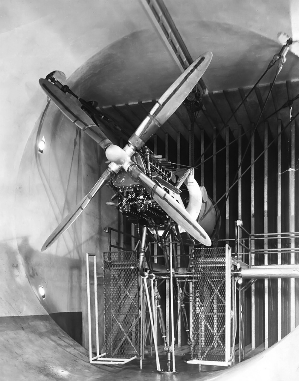
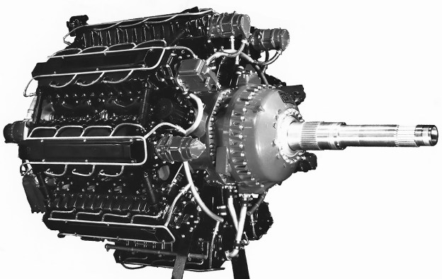
The XR-7755-1 on the test stand with its single propeller shaft. With each of the 36-cylinders displacing 215 cu in (3.5 L), witnessing the XR-7755 run was most likely a very memorable event. Note the robust upper engine support.

The crankshaft had four crankpins, each spaced at 180 degrees. The crankshaft was made up of five sections and assembled through the four one-piece master connecting rods. The crankshaft sections were joined at the rear of the crankpin via face splines and secured by four bolts. Five roller bearings supported the crankshaft in the crankcase.

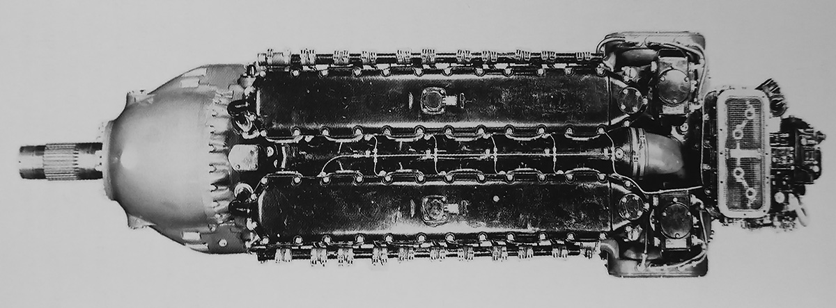
At the rear of the engine was a single-stage, single-speed supercharger. The supercharger’s impeller was 14.4 in (366 mm) in diameter and spun at six times crankshaft speed. The supercharger fed air to nine intake manifolds, each mating with the right side of a cylinder bank. Fuel was provided to the cylinder via either a carburetor or fuel injection. Individual exhaust stacks were attached to the left side of each cylinder. Provisions were also made to incorporate two turbosuperchargers.

Although a single rotation engine was tested, the engine accommodated contra-rotating propellers using SAE #60L-80 spline shafts. The inner shaft rotated counterclockwise, and the outer shaft rotated clockwise. A two-speed planetary propeller gear reduction was hydraulically shifted by engine oil boosted to 300 psi (20.68 bar) by a pump in the nose case. A .2460 reduction was available for high engine speeds, and a .3536 reduction was used for cruise operations with low engine rpm. Due to its size, the XR-7755 required two starters. Both starters were mounted vertically on the crankcase in front of the cylinder banks; one was at the 2:30 position, and the other was at the 9:30 position.

Lycoming XR-7755-1 Maxwell and Cervinsky

Lycoming workers Red Maxwell (left) and Paul Cervinsky (right) pose next to the completed XR-7755-1. It appears Maxwell is ready for the big engine to be stuffed in an airframe to see what it will do. Note the ring on the nose case and around the propeller shaft. No other image found has that ring.

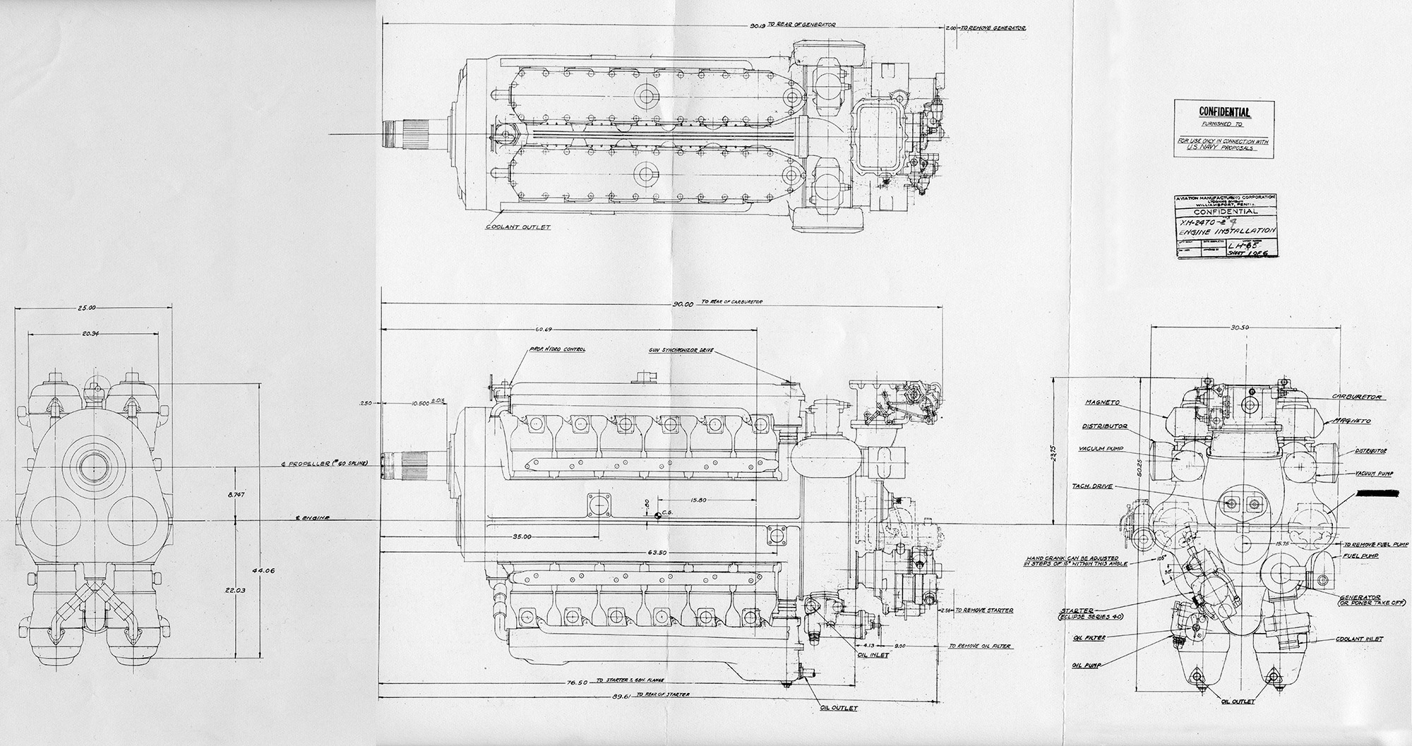
The XR-7755 had a 6.375 in (162 mm) bore and a 6.75 in (171 mm) stroke. The engine displaced 7,756 cu in (127.1 L) and had a compression ratio of 8.5 to 1. The XR-7755 produced 5,000 hp (3,728 kW) at 2,600 rpm (.2460 propeller gear) for takeoff, 4,000 hp (2,983 kW) at 2,300 rpm (.2460 propeller gear) for normal operation, and 3,000 hp (2,237 kW) at 2,100 rpm (.3536 propeller gear) for cruise power. Specific fuel consumption at normal cruise power was .43 lb/hp/hr (262 g/kW/hr), but the rate dropped to around .38 lb/hp/hr (231 g/kW/hr) at low cruise power of around 1,500 hp (1,119 kW). The engine was 61.0 in (1.55 m) in diameter, 66.25 in (1.68 m) tall, and 121.35 in (3.08 m) long. The XR-7755 weighed 6,050 lb (2,744 kg).

Lycoming XR-7755 ad Dec 1946

Lycoming ad from December 1946 featuring the XR-7755. If the engine was not going to go into production, Lycoming might as well get some press out of it. One can only wonder how those responsible for marketing imagined the huge, liquid-cooled engine would factor into the decision-making process of a person buying a small, air-cooled engine.

The XR-7755 was first run in July 1946. At the time, some 10,000 hours of single-cylinder testing had been completed. The Lycoming factory was located near a residential area. Reportedly, a nearby grocery store’s canned goods would vibrate off the shelves as the XR-7755 underwent high-power tests. A good neighbor, Lycoming went to the store and installed strips on the shelf edges to keep the cans from falling. At takeoff power, the XR-7755’s fuel consumption was 580 gallons (2,196 L) per hour, or 20.62 fl oz (.61 L) per second. The engine’s coolant pump flowed 750 gpm (2,839 l/m) to dissipate 95,600 BTUs (24,107 kcal) per minute. That is 2,504 hp (1,681 kW) of heat being rejected into the coolant, and the system’s flow rate was enough to fill a 55 gallon (208 L) drum every 4.4 seconds. The oil pump circulated 71 gpm (269 l/m) at 100 psi (6.89 bar). The oil system absorbed 25,500 BTUs (6,430 kcal) per minute, which is 601 hp (448 kW). Lycoming had an optimistic opinion of the engine and believed that an output of 7,000 hp (5,220 kW) was possible.

Most sources indicate that two XR-7755 engines were built: an XR-7755-1 with a single rotation propeller shaft and an XR-7755-3 with a contra-rotating propeller shaft. Both of these engines used carburetors. There is some indication, including the recollections of those who had family members involved with the project, that a third engine was built: an XR-7755-5 with fuel injection. Reportedly, the -1 underwent a 50-hour test run, but the results are not known. The -3 was delivered to the AAF in 1946, but it is unlikely this engine underwent much testing. It is not clear what happened to the -5, if it was completed. By the time the XR-7755 had run, the concept of an aircraft larger than the Convair B-36 Peacemaker had fallen out of favor, as had the idea of modifying the B-36 with larger piston engines. Rather, jets would be used to improve performance of the aircraft. There was no application for the XR-7755 in a post-war world with the performance of jet aircraft quickly being realized. The XR-7755 never flew.

Lycoming XR-7755 AAF Fair Oct 1945

The XR-7755 on display at the Army Air Forces Fair held at Wright Field, Ohio in October 1945. Note what appears to be a mockup of the contra-rotating propeller shafts.

One curious anomaly in the XR-7755’s story is an appearance of the engine at the Army Air Forces Fair held at Wright Field, Ohio in October 1945. This predates the engine’s run date and its supposed delivery to the AAF. However, the engine appears to have a mockup of its contra-rotating propeller shafts installed. It would seem that the engine is not complete and was shipped the 460 miles (740 km) from Lycoming’s factory in Williamsport, Pennsylvania to Dayton, Ohio to be displayed with other unusual treasures from the war. Presumably, the engine was returned to Lycoming after the show and was subsequently completed and tested in 1946.

The sole XR-7755-3 has been preserved by the Smithsonian National Air and Space Museum and is on display in the Steven F. Udvar-Hazy Center in Chantilly, Virginia. Many consider the XR-7755 the largest aircraft engine ever built. However, the Soviet IAM M-44 (8,107 cu in / 132.8 L) of 1933 and Yakovlev M-501 (8,760 cu in / 143.6 L) of 1952 were larger engines. At the time it first ran, the XR-7755 was the world’s most powerful reciprocating aircraft engine.

Lycoming XR-7755-3 NASM

The restored XR-7755-3 on display in the Steven F. Udvar-Hazy Center of the Smithsonian National Air and Space Museum. The bottom of the engine is on the left, marked by the drain tube from the gear reduction housing and the sump built into the valve cover. Note the two spark plug leads for each cylinder passing through opposite sides of the valve covers. (Sanjay Acharya image via Wikimedia Commons)

Sources:
– “5,000-Hp. Lycoming Revealed” by J. H. Carpenter, Aviation (December 1946)
Lycoming XR-7755 Aircraft Engine and Engineering Laboratories by Lycoming Division, The Aviation Corporation (31 October 1946)
– “The Evolution of Reciprocating Engines at Lycoming” by A. E. Light, AIAA: Evolution of Aircraft/Aerospace Structures and Materials Symposium (24–25 April 1985)
Aircraft Engines of the World 1948 by Paul Wilkinson (1948)
The History of North American Small Gas Turbine Aircraft Engines by Richard A. Leyes II and William A. Fleming (1999)
Studebaker’s XH-9350 and Their Other Aircraft Engines by William Pearce (2018)
https://generalaviationnews.com/2007/04/20/the-xr-7755-the-whole-story/
https://airandspace.si.edu/collection-objects/lycoming-xr-7755-3-radial-36-engine

Lycoming XH-2470 side

Lycoming XH-2470 24-Cylinder Aircraft Engine

By William Pearce

The Lycoming Division of the Aviation Manufacturing Corporation was located in Williamsport (Lycoming County), Pennsylvania. The company had started producing aircraft engines in the late 1920s. In 1937, Lycoming became aware that its most powerful engine to date, the 12-cylinder O-1230, would not produce the power needed for future frontline military aircraft. Development of the O-1230 engine started in 1933, but the anticipated power needs of state-of-the-art aircraft were beyond what the 1,200 hp (895 kW) engine could provide. Lycoming moved quickly to apply knowledge gained from the O-1230 to a new aircraft engine.

Lycoming XH-2470 side

The design of the Lycoming XH-2470 started with the concept of mounting two O-1230 engines to a common crankcase. Note that the propeller shaft is raised above the centerline of the engine.

Lycoming started the design of its new engine in 1938, and detailed design work commenced in mid-1939. The 24-cylinder engine had an H-configuration and consisted of components from two O-1230 engines combined with a new crankcase. The new two-piece aluminum crankcase was split horizontally and accommodated a left and right crankshaft. Each crankshaft served two banks of six cylinders, with one bank above the engine and the other bank below. Fork-and-blade connecting rods were used, with the forked rods serving the lower cylinders. The H-24 engine was designated XH-2470 and given the “Materiel, Experimental” code MX-211. The US Army Air Corps (AAC) initially felt that the engine was too small, but the US Navy supported the design. The Navy ordered a single prototype engine on 11 December 1939, and the AAC started to show some interest in the engine in 1940.

The Lycoming XH-2470 utilized individual cylinders that consisted of a steel barrel screwed and shrunk into an aluminum head. The liquid-cooled cylinder was surrounded by a steel water jacket. The aluminum head had a hemispherical combustion chamber with one intake valve and one sodium-cooled exhaust valve. A cam box was mounted to the top of each cylinder bank, and each cam box contained a single camshaft that was shaft-driven from the rear of the engine.

Lycoming XH-2740 top

Top view of the XH-2470 shows the intake manifold positioned between the cylinder banks. The narrow engine could be installed horizontally (on its side) in an aircraft’s wing. Bell and Northrop pursued this installation for project aircraft, but the designs were not built.

A downdraft carburetor fed fuel into the supercharger’s 12 in (305 mm) diameter impeller mounted to the rear of the engine. Lycoming had experimented with direct fuel injection on test cylinders and planned to have fuel injection available for the XH-2470, but it is unlikely that any complete engines ever used fuel injection. The XH-2470-1, -3, and -7 engines had a single-speed, single-stage supercharger that was driven at 6.142 times crankshaft speed. The XH-2470-5 had a two-speed supercharger that was driven at 6.06 and 7.88 times crankshaft speed. Intake manifolds ran between the upper and lower cylinder banks. Depending on the installation, exhaust gases were either expelled from the outer side of the cylinders via individual stacks or collected in a manifold common to each cylinder bank. Provisions were made for the engine to accommodate a turbosupercharger.

The XH-2470-1, -3, and -5 were available with a single-rotation propeller shaft using a SAE #60 spline shaft. The -1 and -3 had a .38 gear reduction. The -5 was listed as having a two-speed reduction, but the ratios have not been found. The XH-2470-7 had contra-rotating propeller shafts and a two-speed gear reduction with speeds of .433 and .321. The contra-rotating shafts were SAE #40-60 splines, with the inner shaft rotating counterclockwise and the outer shaft rotating clockwise. The gear reduction for all engines was achieved through spur gears, and the propeller shaft was positioned above the engine’s centerline. The engine could be installed in either a vertical or horizontal position.

Lycoming XH-2470-2 drawing

The XH-2470-2 and -4 were engines intended for the Navy. The -2 was similar to the AAF’s engine with a single propeller shaft. The -4 had contra-rotating propeller shafts and was similar to the -7.

The H-2470 had a 5.25 in (133 mm) bore and a 4.75 in (121 mm) stroke. The engine’s total displacement was 2,468 cu in (40.4 L), and it had a 6.5 to 1 compression ratio. The H-2470 produced 2,300 hp (1,715 kW) at 3,300 rpm at 1,500 ft (457 m) for takeoff, 2,000 hp (1,491 kW) at 3,100 rpm at 3,500 ft (1,067 kW) for normal operation, and 1,300 hp (969 kW) at 2,400 rpm at 15,000 ft (4,572 m) for cruise operation. In addition, the two-speed supercharged engine could achieve 1,900 hp (1,417 kW) at 3,300 rpm at 15,000 ft (4,572 m) for emergency power and 1,750 hp (1,305 kW) at 3,100 rpm at 15,000 ft (4,572 m) for normal operation. The XH-2470 had a 3,720-rpm overspeed limit for diving operations. The single-rotation engines were 89.9 in (2.28 m) long, 30.5 in (.77 m) wide, 50.3 in (1.28 m) tall, and weighed 2,430 lb (1,102 kg). The contra-rotating XH-2470-7 was approximately 114 in (2.90 m) long and weighed 2,600 lb (1,179 kg).

Before the XH-2470 had even run, Lycoming proposed a variant of the engine to satisfy the AAC’s Request for Data R40-D, which was issued on 6 March 1940. R40-D sought the design of a 4,000 to 5,500 hp (2,983 to 4,101 kW) aircraft engine for use in long-range bombers. Lycoming proposed coupling two H-2470 engines together, creating a 48-cylinder XH-4940. The XH-4940 would produce 4,800 hp (3,579 kW) at 3,100 rpm up to 8,500 ft (2,591 m) with the aid of a single-speed, single-stage supercharger. The engine had a projected maximum speed of 3,400 rpm and would weigh 6,200 lb (2,812 kg). The AAC’s R40-D ended up going nowhere, and the request was cancelled in mid-1940.

Lycoming XH-2470 test stand

An XH-2470 mounted on a test stand with a tractor propeller. Installed in the XP-54 as a pusher; the blades on the XH-2470 had their angle reversed. Note the individual exhaust stacks.

The XH-2470 was first run in July 1940. The engine was proposed for the Curtiss XF14C Naval fighter and the Vultee XP-54 Swoose Goose AAC fighter. The XP-54’s original power plant was the Pratt & Whitney X-1800 (XH-2240 / XH-2600), but development of this engine stopped in October 1940. It was the cancellation of the X-1800 that led to the AAC’s interest in the XH-2470, and the AAC ordered 25 (later increased to 50) engines in October 1940. The AAC was also interested in potentially using the XH-2470 to power the Lockheed XP-58 Chain Lightning. Bell and Northrop also expressed interest in the engine for future projects.

The XH-2470 completed a Navy acceptance test in April 1941. At the time, the XF14C and XP-54 prototypes were in the detailed design stage. However, the Army Air Force (AAF—the AAC had changed its name in June 1941) continued to alter the XP-54 requirements throughout 1941. Added to the Vultee project were Turbosuperchargers, a pressurized cockpit, and the option of the Wright R-2160 Tornado engine. It was not until 1942 when R-2160 development was seriously behind schedule that the engine was dropped from the XP-54 and a more focused installation of the XH-2470 was presented. An XH-2470-7 engine with contra-rotating propellers was intended for the XP-54, but a single rotation engine was substituted because of delays with the contra-rotating gearbox. The AAF specified two Wright TSBB turbosuperchargers for the first XP-54 prototype and a single, experimental General Electric (GE) XCM turbosupercharger for the second aircraft. Reportedly, the Navy ordered 100 XH-2470 engines in May 1942. However, this may have been a total of 100 engines on order with 50 going to the AAF and 50 to the Navy.

The first XP-54 (41-1210) made its first flight on 15 January 1943, taking off from Muroc (now Edwards) Air Force Base, California. With the exception of the first flight, the XH-2470 engine installed in the XP-54 turned a 12 ft 2 in (3.71 m) Hamilton Standard propeller. Although the aircraft handled well, its development had suffered through constant changes in design and intended role. The aircraft underperformed, and the XH-2470 engine had some issues, such as oil foaming at high RPM or at altitudes above 20,000 ft (6,096 m).

Lycoming XH-2470 Vultee XP-54

The Vultee XP-54 was a very large aircraft. Even so, the installation of the XH-2470 appears to be quite cramped. Note the large exhaust manifold linking the engine to the turbosupercharger, which was positioned behind the cockpit.

The first XP-54 was flown to Wright Field, Ohio on 28 October 1943. After the next flight, a close inspection of the XH-2470 revealed some minor issues as well as damage to the supercharger impeller. The engine was removed and sent to Lycoming for repairs. The cost to fix the engine was more than the AAF was willing to pay, which showed the AAF’s lack of interest in the XH-2470 program. The first XP-54 was removed from flight status and used as a source of spare parts for the second XP-54 aircraft. The first XP-54 had completed 86 flights and accumulated 63.2 hours of flight time.

To make matters worse, the Navy cancelled its XH-2470 order in December 1943, deciding to power the XF14C with a turbosupercharged Wright R-3350 instead. Factors that influenced this change were the Navy’s long-standing preference for air-cooled engines, a shift of the XF14C’s role to that of a high-altitude fighter, issues with the XH-2470’s developmental progress, and doubts that the engine would be ready in time to see combat during World War II. At the same time, Lycoming had moved on to another aircraft engine project, the 36-cylinder XR-7755. Lycoming had invested over $1,000,000 of its own money into the XH-2470 engine.

Lycoming XH-2470 Vultee XP-54 top

The two exhaust outlets from the turbosupercharger protrude quite visibly behind the cockpit. The panel behind the exhaust was stainless steel, and hot exhaust burned the paint off the cowling on early flights. The upper cowling was later replaced with an unpainted stainless steel unit, and the rudders were painted around the same time. (Aerospace Legacy Foundation Archive image)

The second XP-54 prototype (42-108994, but incorrectly painted as 41-1211) made its first flight on 24 May 1944, taking off from Vultee Field. After at least three flights, the GE XCM turbosupercharger and the XH-2470 were removed from the aircraft. Some incompatibility between the turbosupercharger and engine had caused damage to both units. A new engine and turbosupercharger were installed, and the XP-54 flew again in December 1944. The second XP-54 made at least 10 flights, the last ending with an engine failure on 2 April 1945. The airframe had accumulated 10.7 hours of flight time.

At least one XH-2470 engine has been preserved. An XH-2470-7 is in storage at the Smithsonian National Air and Space Museum. The engine, which was never installed in any aircraft, has contra-rotating propellers and a two-speed gear reduction. The Smithsonian also lists an XH-2470-1 engine from the XP-54 in its inventory. However, no further evidence of this engine’s existence has been found.

The preserved XH-2470-7 is in storage at the Smithsonian National Air and Space Museum. Although the engine was never installed in any aircraft, at least it may be displayed one day. (NASM image)

The preserved XH-2470-7 is in storage at the Smithsonian National Air and Space Museum. Although the engine was never installed in any aircraft, at least it may be displayed one day. (NASM image)

Sources:
Aircraft Engines of the World 1947 by Paul Wilkinson (1947)
American Secret Pusher Fighters of World War II by Gerald H. Balzer (2008)
Development of Aircraft Engines and Fuels by Robert Schlaifer and S. D. Heron (1950)
U.S. Experimental & Prototype Aircraft Projects Fighters 1939–1945 by Bill Norton (2008)
Experimental & Prototype U.S. Air Force Jet Fighters by Dennis R. Jenkins and Tony R. Landis (2008)
The History of North American Small Gas Turbine Aircraft Engines by Richard A. Leyes II and William A. Fleming (1999)
Studebaker’s XH-9350 and Their Other Aircraft Engines by William Pearce (2018)
Preliminary Model Specification for Engine Aircraft Model XH-2470-4 for Opposite Rotating Propellers by Aviation Manufacturing Corporation Lycoming Division (18 April 1940)
– “The Evolution of Reciprocating Engines at Lycoming” by A. E. Light, AIAA: Evolution of Aircraft/Aerospace Structures and Materials Symposium (24–25 April 1985)
https://airandspace.si.edu/collection-objects/lycoming-xh-2470-7-h-24-engine
https://airandspace.si.edu/collection-objects/lycoming-xh-2470-1-h-24-h-type-engine