Category Archives: World War II

Daimler-Benz-DB-606-engine-front

Daimler-Benz DB 606, DB 610, and DB 613 Doppelmotoren

By William Pearce

In 1936, Siegfried and Walter Günter began design work on the Heinkel He 119, an experimental, unarmed, high-speed light bomber and reconnaissance aircraft. The engine for the He 119 was buried in the fuselage, and the Günter brothers quickly realized that no engine available was capable of providing the desired power in excess of 2,300 hp (1,691 kW). Heinkel requested proposals from Germany’s leading aircraft engine manufacturers. Daimler-Benz responded with a plan to construct a doppelmotor (double engine) by coupling two DB 601 V-12 engines to create the 24-cylinder DB 606. Combining two engines as a single unit was seen as a quick way to double engine power without spending years to develop a new powerplant.

Daimler-Benz-DB-606-engine-front

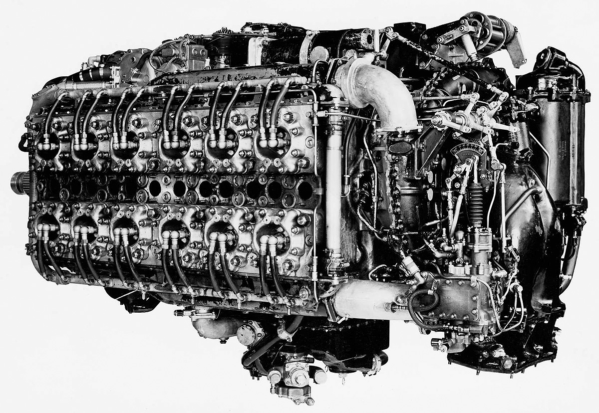
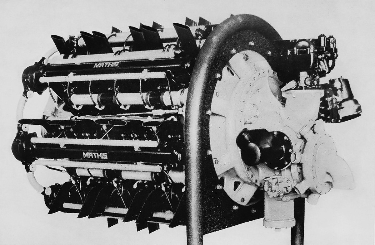
The Daimler-Benz doppelmotoren (double engines) were quite literally formed by combining two separate engines. The DB 606 was made from two DB 601 engines. The levers attached to the combining gear reduction housing controlled the coupling and decoupling of the separate engine sections.

Development of the DB 601 was started in the mid-1930s and based on the DB 600. The main differences between the engines were that the DB 600 used a carburetor and geared supercharger, whereas the DB 601 used fuel injection and a variable speed supercharger. The DB 601 was an inverted, liquid-cooled engine with two banks of six cylinders. Its single-piece Silumin-Gamma (aluminum alloy) crankcase was closed out by a cover affixed to its top side. The six-throw crankshaft was supported by seven main bearings, and each main bearing was secured by four bolts and one transverse bolt that passed through the crankcase. The crankshaft turned counterclockwise. Fork-and-blade connecting rods were used, with the forked rods serving cylinders on the right side of the engine (when viewed from the rear). The connecting rods ran on roller bearings, but the blade rod had an additional plain bearing between it and the roller bearing.

The two cylinder blocks were made from Silumin (aluminum-silicon alloy) and attached to the bottom of the crankcase at a 60 degree angle. Each cylinder block consisted of six cylinders with integral cylinder heads. The dry cylinder liners (barrels) were made of chrome steel and were screwed and shrunk into the upper cylinder block. Threaded liner skirts protruded into the crankcase toward the crankshaft. A locking ring screwed onto each liner skirt and drew and secured the entire cylinder block to the crankcase. The locking ring had “teeth” around its outer edge and was tightened by a special pinion tool that was held secure in the crankcase and rotated the ring.

Each cylinder had two spark plugs mounted on its outer side and a fuel injector mounted on its inner side. The Bosch fuel injection pumps were mounted in the Vee between the cylinder banks. Two intake valves on the inner side of the cylinder brought in air. The combustion gasses were expelled through two sodium-cooled exhaust valves on the outer side of the cylinder. All four valves per cylinder were actuated via rockers by a single overhead (technically underhead) camshaft, which was driven by a vertical shaft at the rear of the engine.

The DB 601’s propeller shaft was driven clockwise via spur gears through a gear reduction housing mounted to the front of the engine. The gear reduction was made so that a gun or cannon could be mounted behind the engine and fire through the Vee between the cylinder banks and out the propeller’s hub. Mounted to the rear of the engine was an accessory section that provided the drives for the magnetos, generator, starter, fuel and oil pumps, and the transversely mounted supercharger.

Daimler-Benz-DB-606-engine-bottom-eng

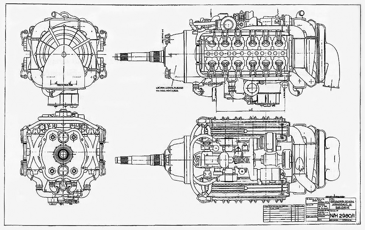
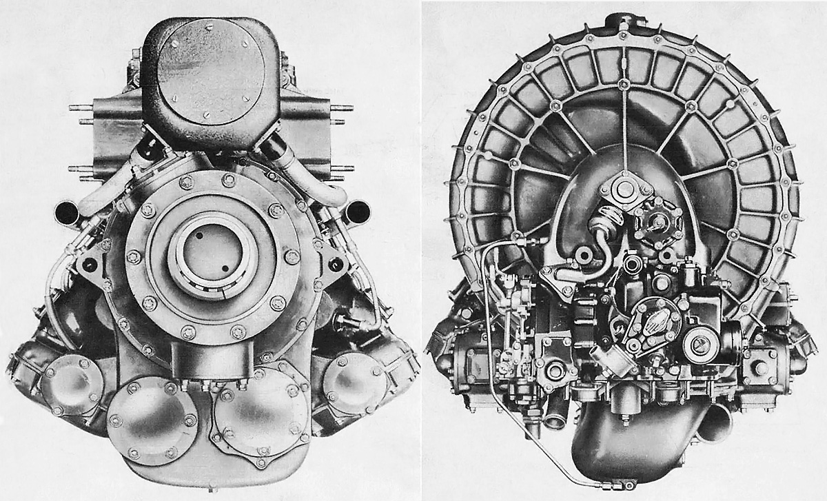
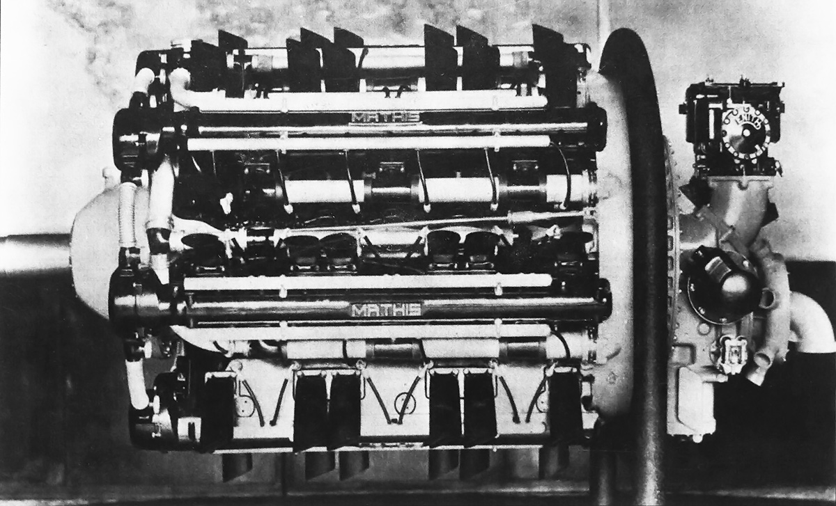
Bottom view of a DB 606 illustrates the separate engine sections. Note the rear engine mount which joined the two engine sections. The fuel injection pump for each engine section can be seen in the Vee between the cylinder banks.

The supercharger was mounted on the left side of the engine and driven from the crankshaft via a variable speed fluid coupling. In simple terms, two oil pumps supplied oil that flowed through the supercharger coupling. One pump continuously supplied the amount of oil needed for the supercharger to operate at its lowest (sea level) speed. The second pump was barometrically controlled and gradually supplied more oil as the aircraft’s altitude increased. At the engine’s critical altitude, the second pump was supplying the maximum amount of oil, and the supercharger was at its maximum speed. There was always some degree of slip in the coupling, but it was minimal (a few percent) at full speed. The variable speed of the supercharger created a gradual power curve rather than the saw-tooth power delivery of two- or three-speed superchargers. Air from the supercharger flowed through an intake manifold that looped in the Vee between the cylinder banks.

To form the DB 606, two DB 601 engines were mounted side-by-side at an included angle of 44 degrees and joined by a common propeller gear reduction. In this configuration, the engine banks formed an inverted W, and the inner cylinder banks were only eight degrees from vertical. The right and left engine sections were respectively referred to as the “W-Motor” (or DB 601 W) and the “X-Motor” (or DB 601 X). The exhaust ports for both inner cylinder banks were positioned in the narrow space between the two engine sections. DB 606 differed from the DB 601 by using the new propeller gear reduction and a modified accessory drive. The two engine sections drove a single propeller, and no gun or cannon could be fitted to fire through the propeller hub. Bolted between the two engine sections and near their rear was a mount for suspending the back of the DB 606 to the aircraft. The left and right engine sections remained separate with the exception of the gear reduction and the rear mount.

The new gear reduction housing combined the output from the two engine sections and fed it into a single propeller shaft, which typically had an extension that was approximately 44 in (1.11 m) long. The combining gear allowed the manual decoupling and recoupling of an engine section. Recoupling could only be accomplished when the engine sections were operating at the same RPM. In addition, an engine section would be automatically decoupled if its speed dropped suddenly compared to the other engine section. The coupling of each engine was accomplished by dogs (often referred to as claws in German literature) on a flange splined to the crankshaft that engaged dogs on a coupler that drove a spur gear in the reduction housing. To disengage an engine section, a lever for that engine section on the gear reduction housing had to be pulled forward. This would pull the coupler toward the propeller and disengage it from the crankshaft. The coupler would still be connected to the gears in the reduction housing. The levers on the engine were linked to levers in the cockpit, and the individual engine sections were started one at a time.

Different combining gear reductions enabled the propeller of the DB 606 to turn either clockwise or counterclockwise without changing the counterclockwise rotation of the engines’ crankshafts. The propeller of the DB 606 A turned clockwise. A 33-tooth gear on each of the two crankshafts meshed with an 80-tooth gear on the propeller shaft to create a .4125 reduction. The combining gear on the DB 606 B incorporated idler gears in the lower housing that enabled the propeller to turn counterclockwise. The idler gears increased the engine’s weight by approximately 88 lb (40 kg). For the DB 606 B, a 31-tooth gear on each of the two crankshafts meshed with 39-tooth idler gears, which engaged the 75-tooth gear on the propeller shaft to create a .4133 reduction. With two fewer gears, the combining gear reduction housing on the DB 606 A was initially smaller with angled corners when compared to that of the DB 606 B. However, to simplify production, later DB 606 A engines used the same larger, more rounded housing as the DB 606 B.

Daimler-Benz DB 606 engine rear

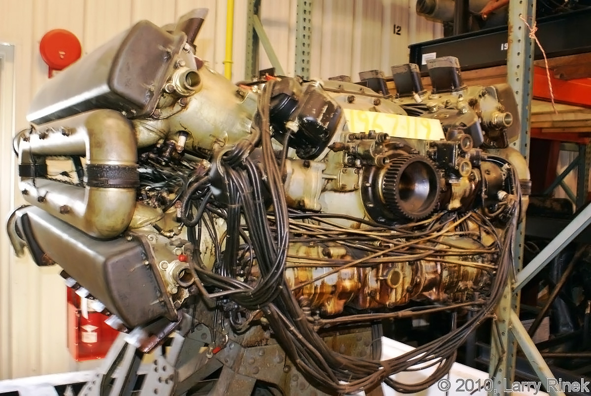
Rear view of a DB 606 displays the mirrored accessories on the back of each engine section. The left engine (X-Motor) had the standard accessory housing and supercharger. The accessory section of the right engine (W-Motor) was unique to the doppelmotor. The square mounting pad for the cannon can be seen at the center of each engine section, but this was not used on the doppelmotoren.

The supercharger and accessory section of the right DB 606 (W-Motor) engine section was basically the same as that used on the DB 601. The supercharger and accessory section of the left DB 606 (X-Motor) engine section was a mirror image of the left section so that the supercharger was on the right side of the engine.

The Daimler-Benz DB 606 A/B had a 5.91 in (150 mm) bore, a 6.30 in (160 mm) stroke, and a total displacement of 4,141 cu in (67.86 L). The engine was 6 ft 10 in (2.08 m) long without an extension shaft, 5 ft 4 in (1.63 m) wide, and 3 ft 6 in (1.06 m) tall. The dry weight of the DB 606 A was 3,263 lb (1,480 kg), and the dry weight of the DB 606 B was 3,373 lb (1,530 kg). Initially, 1,175 hp (864 kW) DB 601 Aa engines were used to create the DB 606 A/B. The supercharger on the DB 601 Aa ran full speed at an altitude of 13,123 ft (4,000 m), and the engine had a compression ratio of 6.9 to 1. For takeoff and emergency power at 2,500 rpm and 20.6 psi (1.42 bar) of boost, the early DB 606 A/B V-series (Versuch, experimental) produced 2,350 hp (1,728 kW) at sea level and 2,200 hp (1,618 kW) at 12,139 ft (3,700 m). For climb and combat power at 2,400 rpm and 19.1 psi (1.32 bar) of boost, the engine produced 2,090 hp (1,537 kW) at sea level and 2,100 hp (1,545 kW) at 13,451 ft (4,100 m). For maximum continuous power at 2,300 rpm and 16.9 psi (1.17 bar) of boost, the engine produced 1,900 hp (1,397 kW) at sea level and 1,760 hp (1,294 kW) at 14,764 ft (4,500 m).

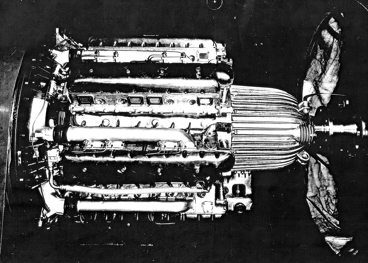
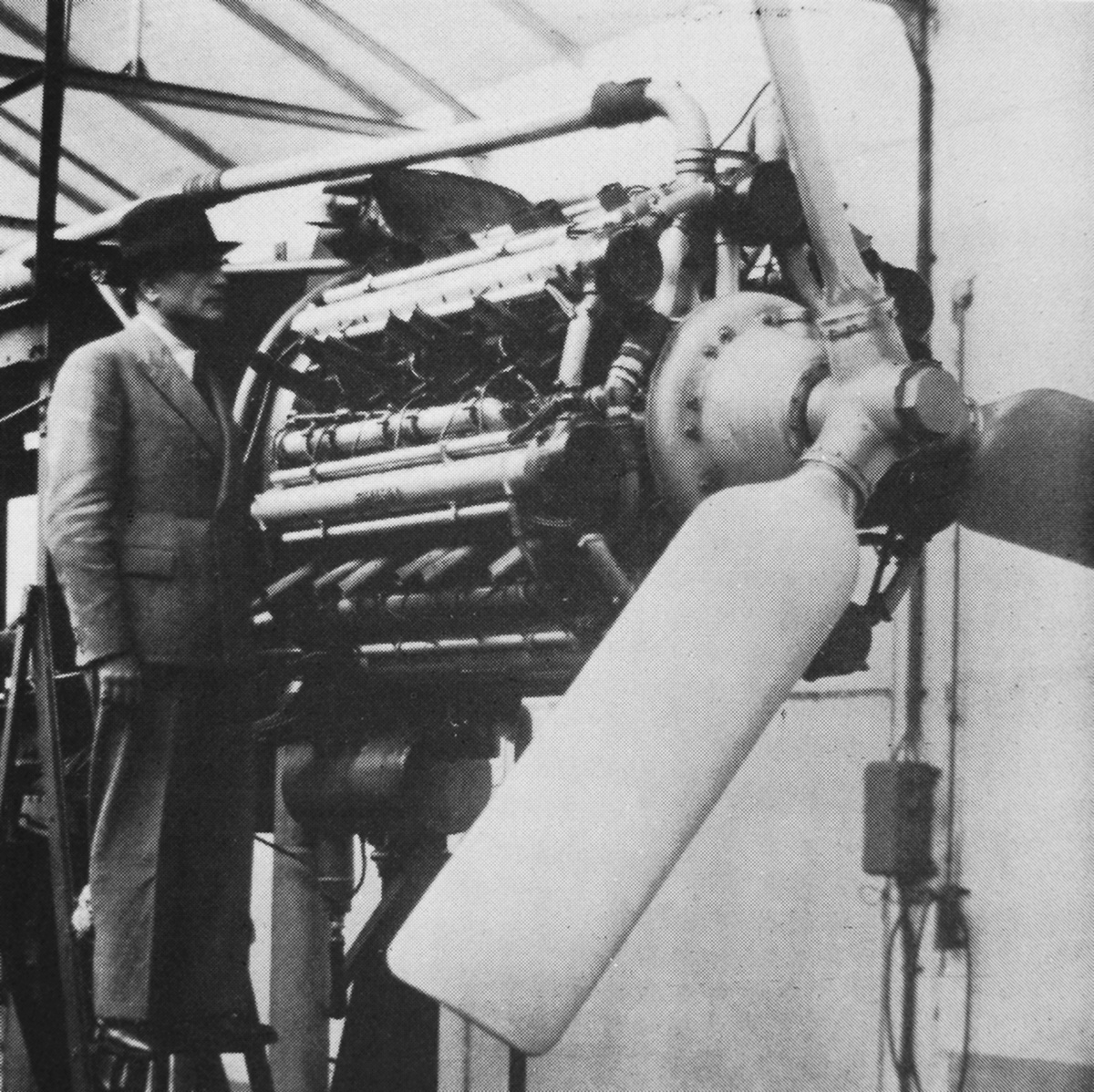
Because it was based on an existing engine, the DB 606 was developed quickly. The engine made its first flight in the He 119 in June 1937 with Gerhard Nitschke at the controls. The single DB 606 was installed in the He 119’s fuselage and drove the 14 ft 1 in (4.30 m) diameter, four-blade propeller via a long extension shaft. DB 606 V1 through V4 powered the four He 119 aircraft that were built, and the engine proved to be reliable in that airframe. One He 119 did crash on 16 December 1937 after a faulty fuel transfer valve caused the engine to quit.

Heinkel also selected the DB 606 to power its new long-range heavy bomber design, which was submitted to the RLM (Reichsluftfahrtministerium, or Germany Air Ministry) in response to their Bomber A specification. The RLM ordered construction of a prototype on 2 June 1937, and the aircraft was soon designated as the Heinkel He 177 Greif (Griffon). Like with the He 119, the He 177 was designed by Siegfried and Walter Günter, although Walter was killed in a car accident on 21 September 1937. As changes in the design requirements mounted, particularly with RLM’s insistence that the He 177 be capable of dive bombing, Siegfried was forced to alter the aircraft and make compromises to its design.

Heinkel-He-119-D-AUTE-DB-606

The DB 606 was designed for use buried in the fuselage of the Heinkel He 119 and powered the propeller via a long extension shaft. This aircraft (D-AUTE) was lost on 16 December 1937 following an engine failure due to a faulty fuel transfer valve.

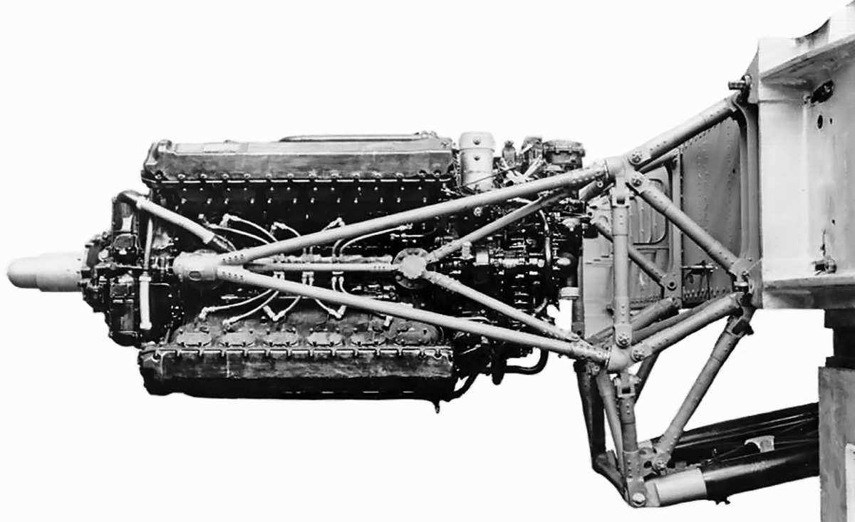
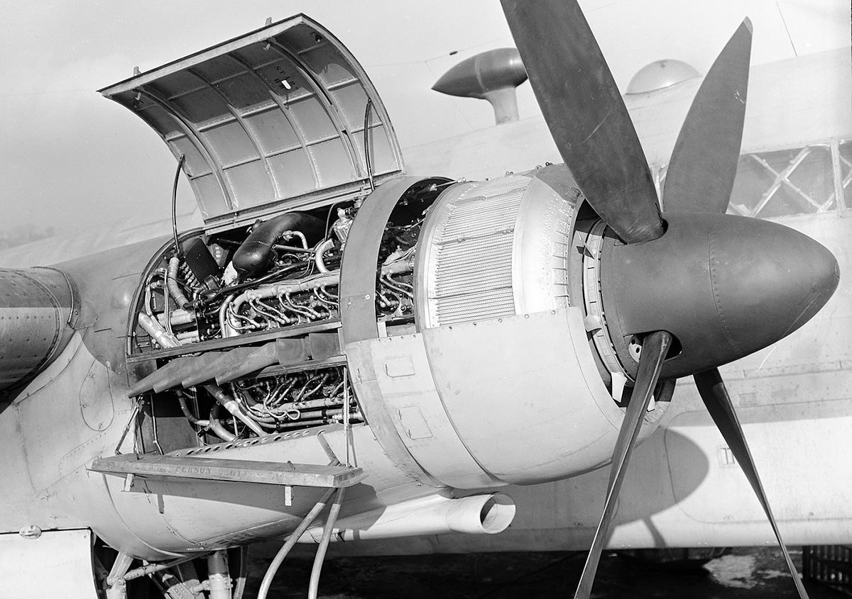
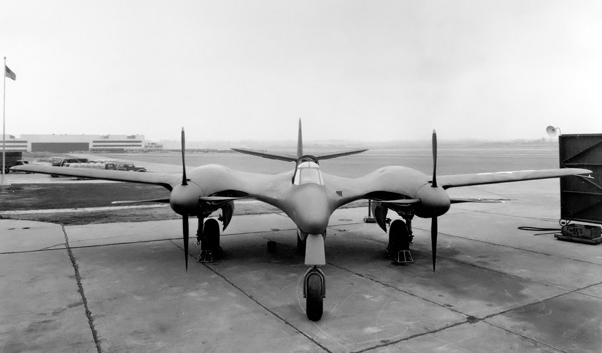
Each of the He 177’s wings had one DB 606 engine installed fairly deep and immediately forward of the main landing gear. Each main gear consisted of two legs, with the inboard leg retracting toward the wing root and the outboard leg retracting toward the wing tip. Because of the cramped installation of the engine and landing gear, there was no firewall behind the DB 606. Room was at such a premium that right-angle fittings were used for connections behind the engine. Originally, surface cooling had been planned, but this was switched to annular radiators installed in the engine nacelle just before the engine. The DB 606’s extension shaft led from the engine, through the radiators, and to the He 177’s four-blade propeller, which was 14 ft 9 in (4.5 m) in diameter.

At least 800 He 177 aircraft had been ordered before the prototype made its first flight on 20 November 1939, piloted by Carl Francke. For reference, the He 177 prototype flew with engines V5 and V6, indicating just how few DB 606s had been produced up to that point. In December 1940, DB 606 A/B-1 engines uprated to 2,700 hp (1,986 kW) were installed in He 177 V6. The uprated DB 606 A/B-1 used two 1,350 hp (993 kW) DB 601 E engines. The supercharger of the uprated DB 601 E ran full speed at an altitude of 15,748 ft (4,800 m).

For takeoff and emergency power at 2,700 rpm and 20.9 psi (1.44 bar) of boost, the DB 606 A/B-1 produced 2,700 hp (1,986 kW) at sea level and 2,650 hp (1,949 kW) at 15,748 ft (4,800 m). For climb and combat power at 2,500 rpm and 19.1 psi (1.32 bar) of boost, the engine produced 2,400 hp (1,765 kW) both at sea level and at 16,076 ft (4,900 m). For maximum continuous power at 2,300 rpm and 16.9 psi (1.17 bar) of boost, the engine produced 2,000 hp (1,471 kW) at sea level and 2,075 hp (1,526 kW) at 16,732 ft (5,100 m).

Starting around 1940, Daimler-Benz used a lower compression ratio in the right (non-supercharger side) cylinder bank. This was due to the crankshaft’s rotation flinging extra oil toward the right cylinders. Some of the oil would get past the piston rings and into the combustion chamber. The presence of this oil increased the possibility of detonation (knock) in the cylinder. The compression ratio was decreased slightly to increase the cylinder’s knock resistance. Because the inner cylinder banks of the doppelmotoren were nearly vertical, they captured more oil than the outer cylinder banks. The inner banks also ran hotter because of their tight installation. The extra oil and the heat both increased the possibility of detonation in the inner cylinder banks. As a result, the inner cylinder banks of the doppelmotoren had a slightly lower compression ratio than that of the outer cylinder banks. For the DB 606 A/B-1, the outer (supercharger side) cylinder banks had a compression ratio of 7.2 to 1, and the inner (non-supercharger side) cylinder banks had a compression ratio of 7.0 to 1.

Heinkel-He-177-A-02-0017-DB-606

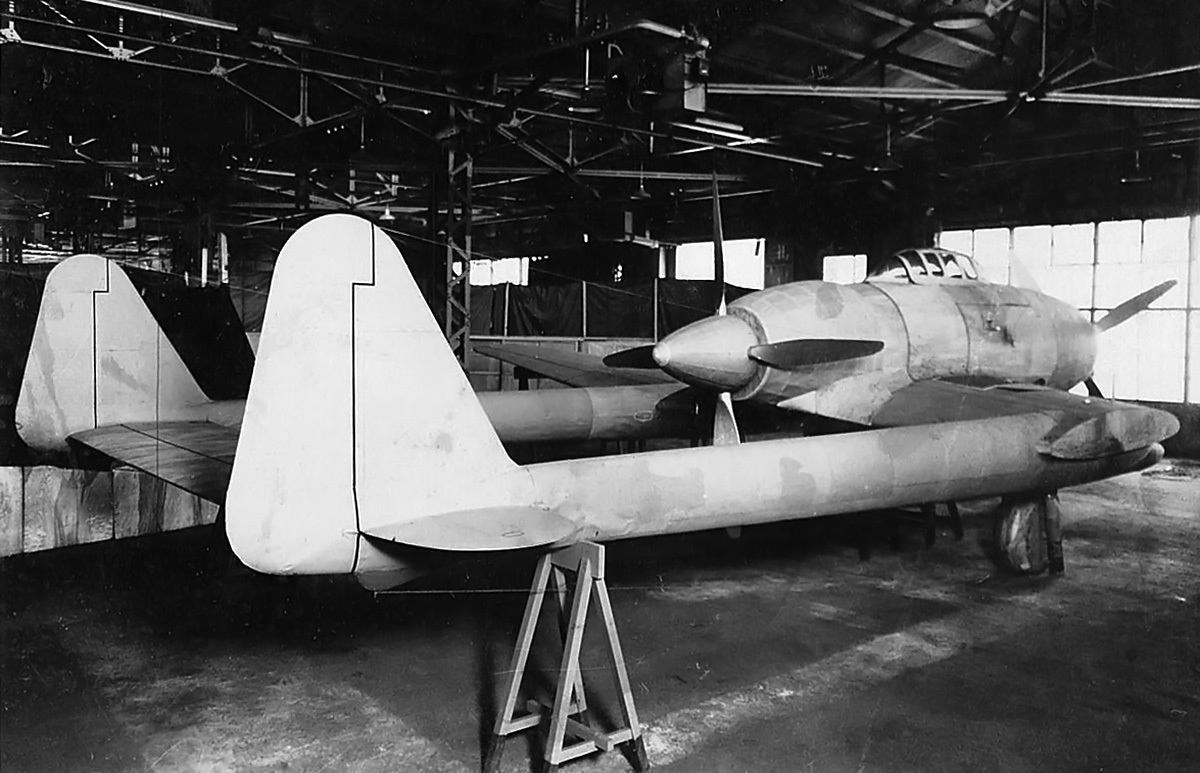
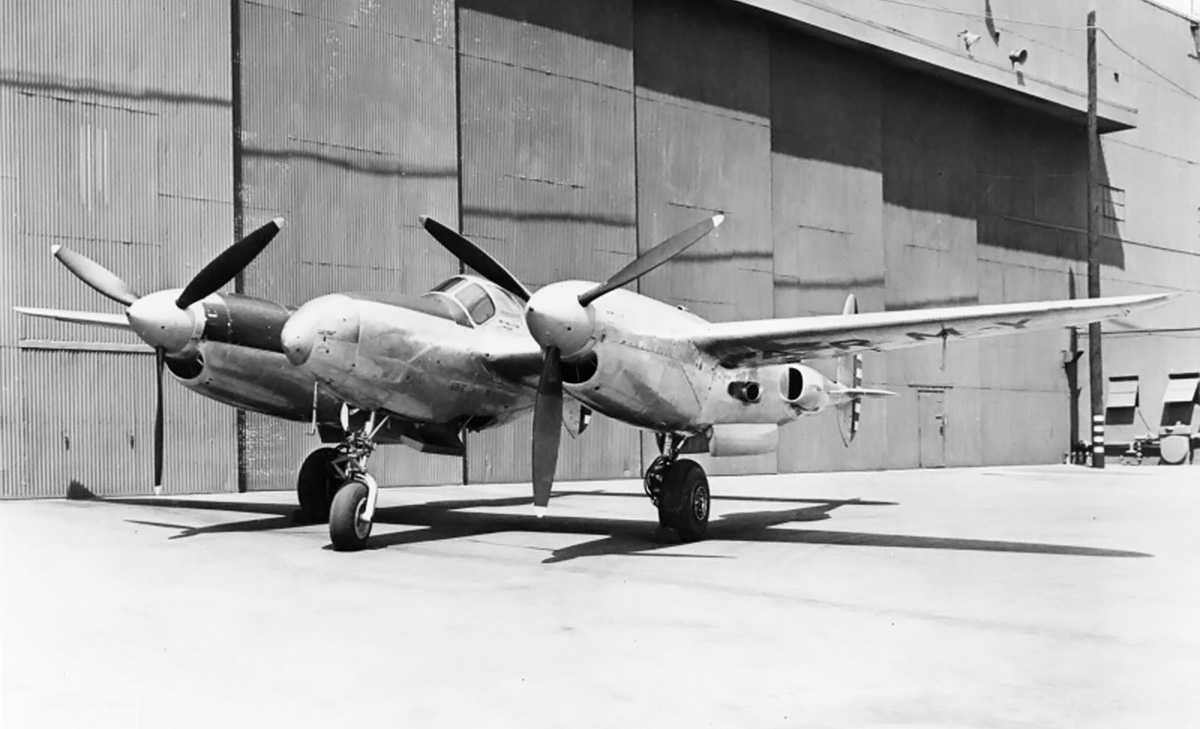
The Heinkel He 177 bomber was designed to take advantage of the reduced drag offered by the DB 606 doppelmotor. However, the engine and its installation proved to be very problematic. The He 177 A-02 pictured above was the tenth He 177 built and second production machine. It was lost in May 1942 during a crash landing after both engines caught fire.

The DB 606 engine and its installation in the He 177 proved to be disastrous. As doppelmotor production picked up, vibration issues were discovered with the two engine sections, and the combining gear required much more development than had been anticipated. There were also issues with failures of the engine couplings. A major DB 606 issue was with its oil circulation at high altitudes. The oil would foam, leading to inadequate lubrication and the subsequent failure of bearings and seizing of pistons. Some of these failures would be catastrophic, with parts (connecting rods) breaking through the crankcase.

But it was the engine installation that caused the biggest issues. The annular radiators provided inadequate cooling, resulting in the engines running hot. The exhaust between the two inner cylinder banks ran so hot that any fuel or oil that dripped down from leaking fittings or during a catastrophic engine failure was ignited. Weeping fittings and seeping seals (partly caused by material shortages and substitutions during the war) were a constant issue, as the leaked fluid would pool and eventually be ignited by the hot exhausts’ radiant heat. Through lack of a firewall, fires in the engine nacelle would spread to the main gear and ignite any leaking hydraulic fluid. In addition, the hot exhaust being expelled just forward of the extended main gear was enough to ignite any hydraulic oil that had leaked.

Any fire in the wing spread quickly and spelled disaster for the aircraft and its crew. With the crew siting well forward of the engines, fires often went unnoticed until severe damage had occurred. Despite the best efforts of maintenance crews, the DB 606 engines needed constant attention and proved very difficult to service. Engine fires occurred with such regularity that crews referred to the He 177 as the Luftwaffenfeuerzeug, or Luftwaffe’s cigarette lighter. To resolve the engine issues, suggestions were made to extend the engine nacelle, install a firewall, reroute lines to prevent the pooling of fluids under the engine, and redesign the exhaust system. Such changes were ignored at first because they would delay He 177 production, which had already been rushed. However, the aircraft was also experiencing a number of structural issues unrelated to the engines that made modifications necessary.

Toward the end of 1942, the He 177 underwent a redesign as the A-3 variant. This aircraft would do away with the troublesome DB 606 engines and replace them with DB 610s. The DB 610 was a doppelmotor consisting of two 1,475 hp (1,085 kW) DB 605 A engines. The DB 605 was a development of the DB 601 that operated at a higher RPM, had an increased bore, and had a higher compression ratio. The DB 605/610 used plain bearings for the connecting rods rather than the roller bearings used on the DB 601/606.

Daimler-Benz-DB-610-engine-side

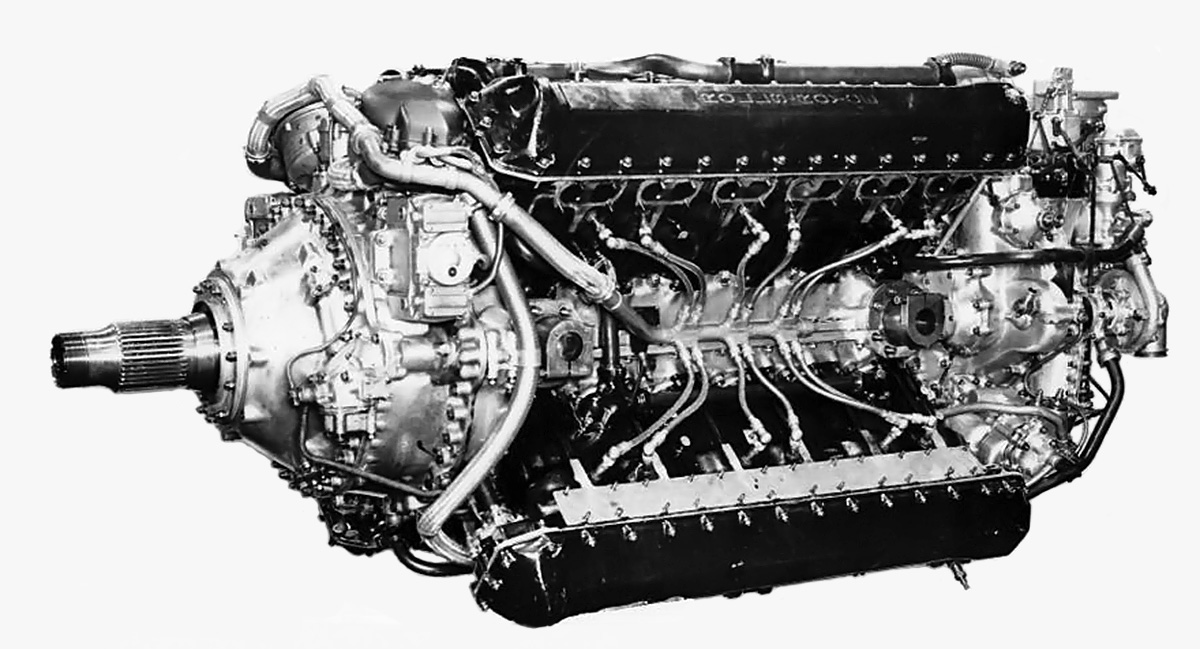
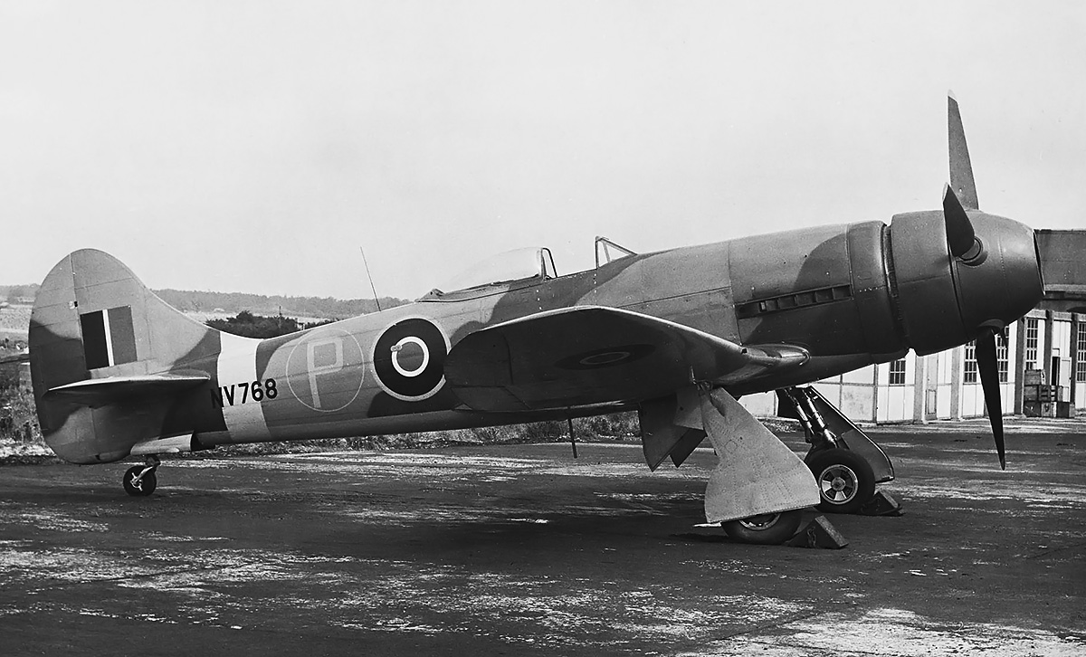
The DB 610 combined two DB 605 engines and was intended to cure the issues with the DB 606. While the DB 610 was more powerful, issues still persisted, and all doppelmotoren proved to be difficult to service and maintain. The propeller extension shaft was typical, being used on the He 177, Ju 288, and NC.3021.

The DB 610 kept the same engine section naming convention as the earlier doppelmotor, with the “W-Motor” (or DB 605 W) as the right section and the “X-Motor” (or DB 605 X) as the left section. The supercharger ran full speed at an altitude of 18,701 ft (5,700 m). The compression ratio of the outer (supercharger side) cylinder banks was 7.5 to 1, and the compression ratio of the inner (non-supercharger side) cylinder banks was 7.3 to 1.

The Daimler-Benz DB 610 A/B had a 6.06 in (154 mm) bore, a 6.30 in (160 mm) stroke, and a total displacement of 4,365 cu in (71.53 L). For takeoff and emergency power at 2,800 rpm and 20.9 psi (1.42 bar) of boost, the engine produced 2,950 hp (2,170 kW) at sea level and 2,700 hp (1,986 kW) at 18,701 ft (5,700 m). For climb and combat power at 2,600 rpm and 19.1 psi (1.32 bar) of boost, the engine produced 2,620 hp (1,927 kW) at sea level and 2,500 hp (1,839 kW) at 19,029 ft (5,800 m). For maximum continuous power at 2,300 rpm and 16.9 psi (1.17 bar) of boost, the engine produced 2,150 hp (1,581 kW) at sea level and 2,160 hp (1,589 kW) at 18,045 ft (5,500 m). The DB 610 was the same size as the DB 606: 6 ft 10 in (2.08 m) long, 5 ft 4 in (1.63 m) wide, and 3 ft 6 in (1.06 m) tall; however, it was around 130 lb (60 kg) heavier. The dry weight of the DB 610 A was 3,395 lb (1,540 kg), and the dry weight of the DB 610 B was 3,483 lb (1,580 kg).

The DB 610 installation on the He 177 A-3 was extended 200 mm (7.9 in) forward, and a firewall was incorporated behind the engine. On 22 March 1943, the DB 610 made its first flight in an He 177 (V19, VF+QA). Although reliability had been improved, engine fires still occurred, and the DB 610 suffered from the same engine coupling failures that had been experienced with the DB 606. In May 1942, Hermann Göring, commander of the Luftwaffe, made the following comment in reference to the He 177 and DB 606: “I have never been so furious as when I saw this engine. …Nobody mentioned this hocus-pocus with two welded-together engines to me at all.” By early 1944, plans were in motion to build He 177 with four separate engines, a suggestion that Heinkel had discussed back in late 1938 and proposed in mid-1939. Further production and development of the He 177 was abandoned on 1 July 1944. Once the Allies had landed on the continent, German aircraft production was focused on defensive fighters and attackers.

Daimler-Benz-DB-610-engine-rear

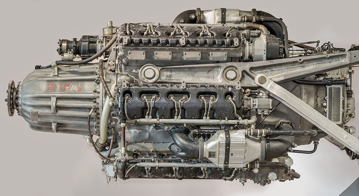
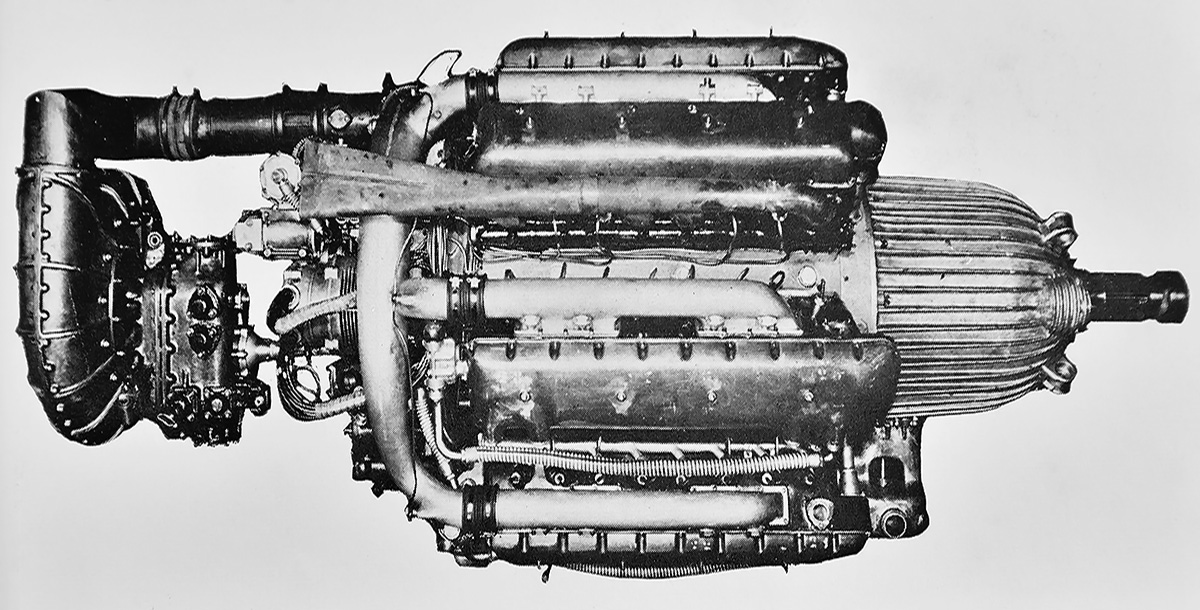
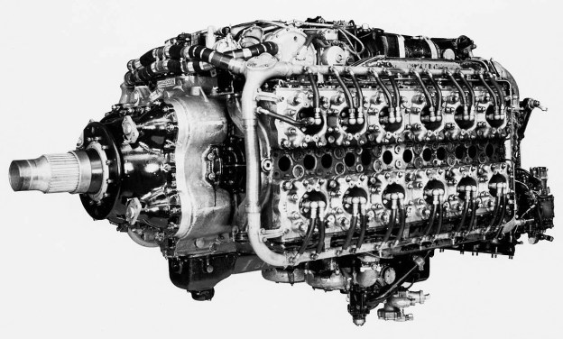
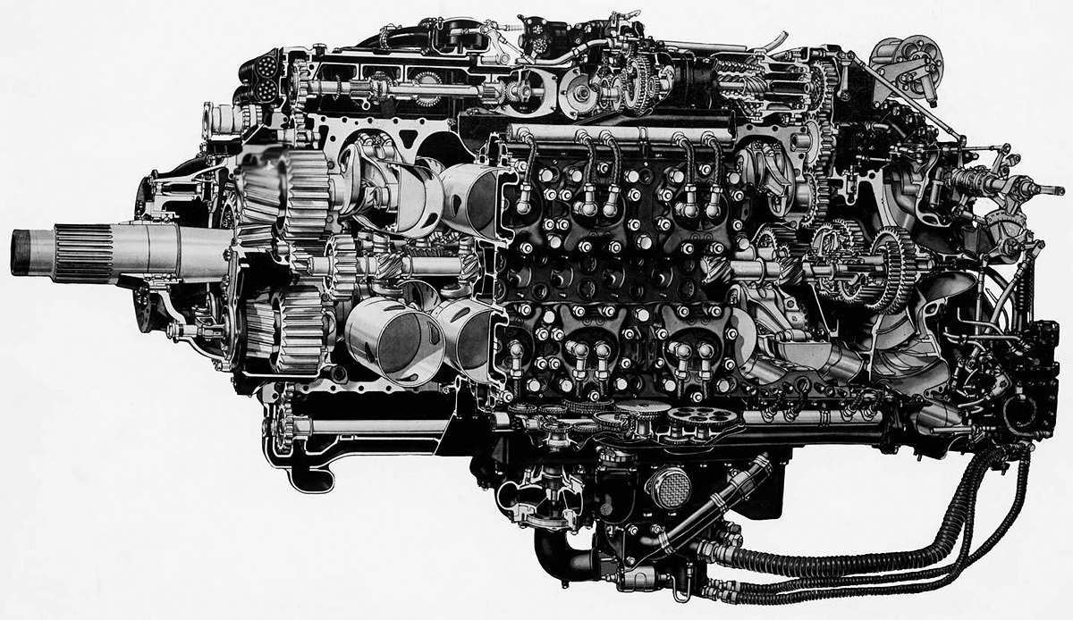
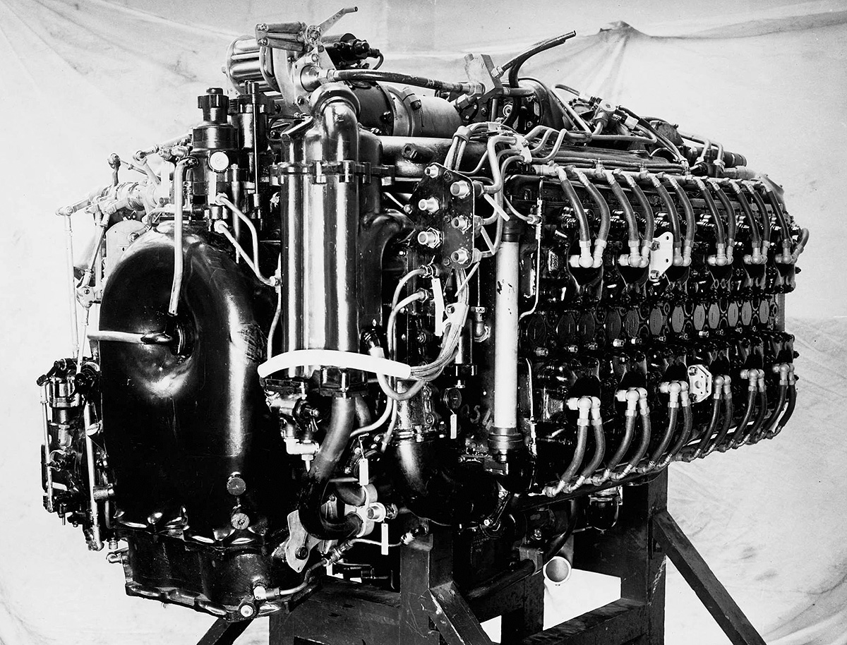
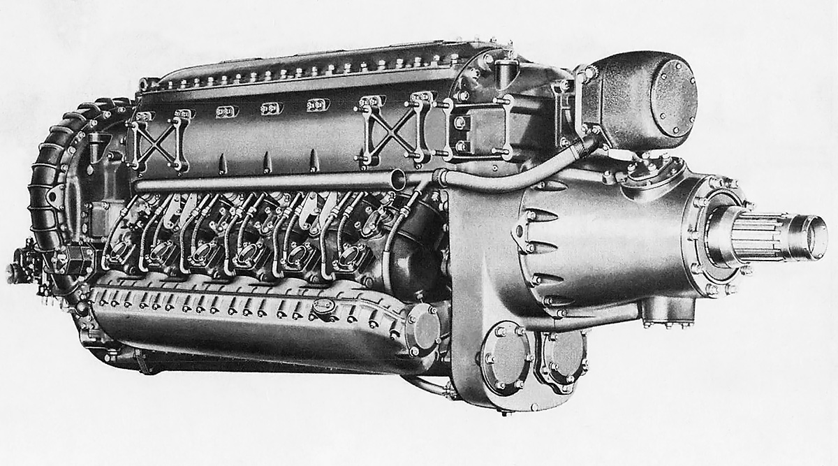
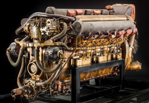
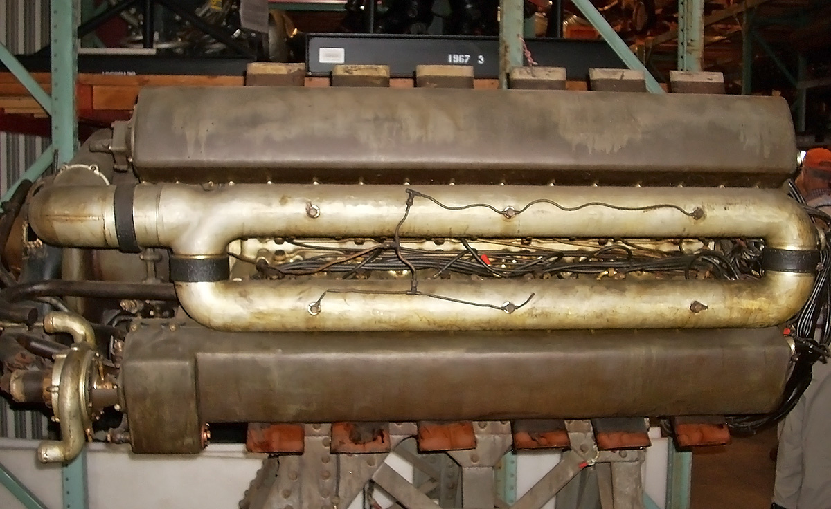
Side view of the DB 610 illustrates the relative ease with which the spark plugs on the outer cylinder banks can be accessed. However, one can imagine the extreme difficulty of accessing the spark plugs of the inner cylinder banks. The bolts on the upper side of the crankcase are the transverse bolts that pass through the main bearing caps.

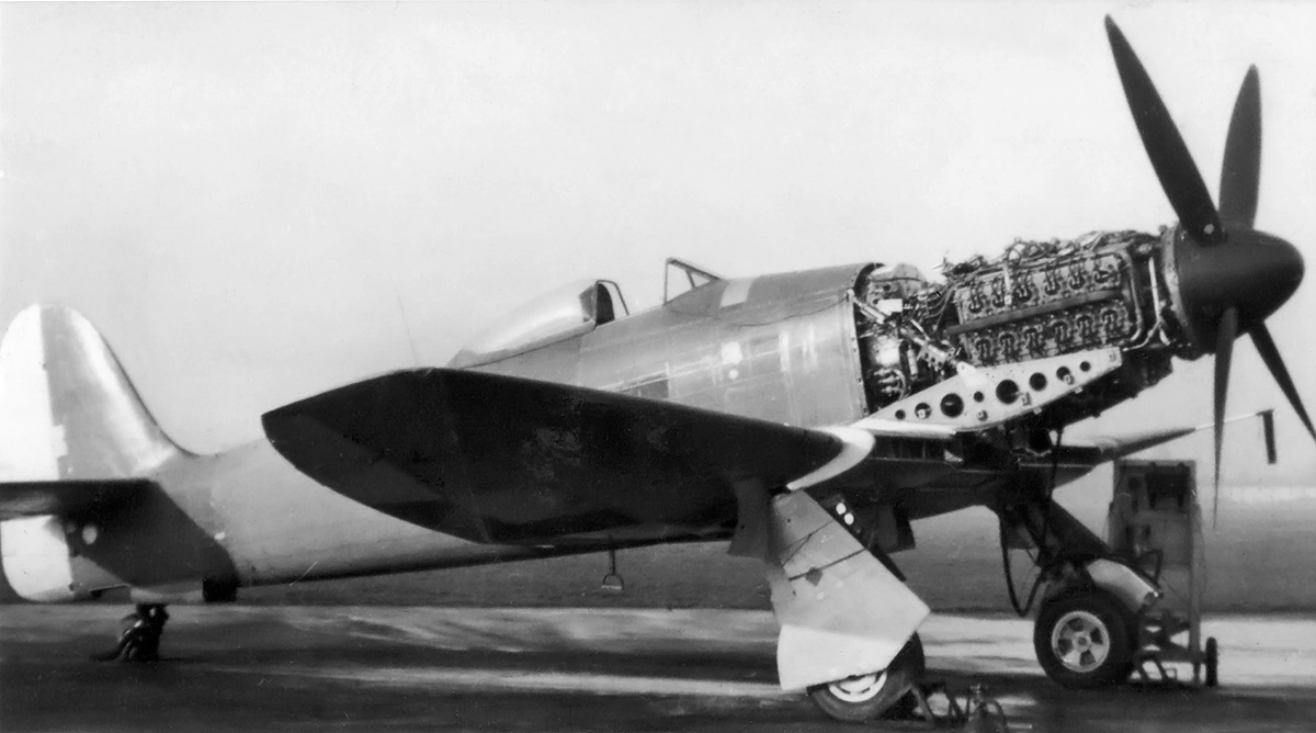
The Daimler-Benz doppelmotoren were also installed in the Junkers Ju 288 bomber. As issues with its intended 24-cylinder Junkers Jumo 222 inline radial engine created a short supply, the DB 606 was substituted in Ju 288 prototypes. A DB 606 engine was installed on each wing in a form-fitting nacelle with an annular radiator at its front. Like with the He 177, the extension shaft connected the engine to the propeller. The DB 606-powered Ju 288 V11 made its first flight in July 1942. Three additional Ju 288s were powered by DB 606 engines. A switch to the DB 610 was made for the Ju 288 V103, which was first flown in the spring of 1943. Five additional Ju 288s were powered with DB 610 engines. The doppelmotor installation in the Ju 288 did not result in the frequent engine fires experienced with the He 177. The DB 610 was planned for later Ju 288 C and D variants, but the aircraft were cancelled.

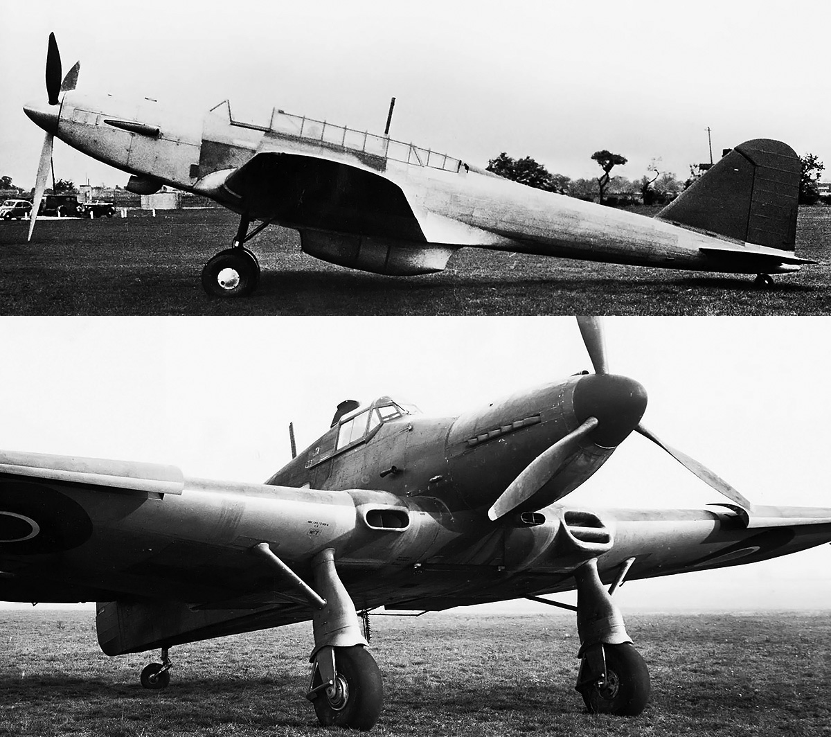
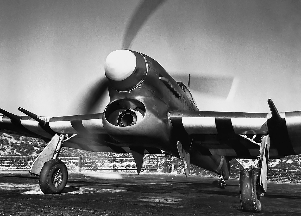
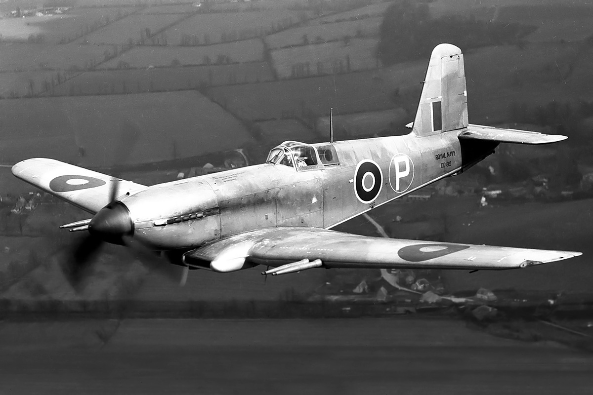
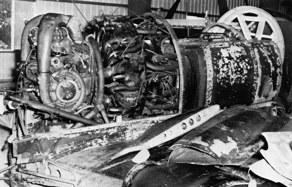
Post war, a DB 610 was used in the French SNCAC NC.3021 Belphégor high altitude research aircraft. The large single-engine aircraft had an annular radiator positioned in front of the DB 610 engine. The NC.3021 was first flown on 6 June 1946. Issues servicing the DB 610 were encountered, and the aircraft required much maintenance. SNCAC went bankrupt in mid-1949, and no other funds were provided for the aircraft. The NC.3021 was withdrawn from testing in 1950 and scrapped.

Development of the DB 613, a third doppelmotor, had a lower priority than that of the DB 606 and DB 610. With what appeared to be the successful creation of the DB 606, Daimler-Benz decided to apply the same doppelmotor concept to the DB 603 engine. The DB 603 was based on and built like the DB 601, but it had an enlarged bore and an elongated stroke. Compared to the DB 601, the DB 603 had slightly decreased supercharging at takeoff power but an increased compression ratio. The compression ratio of the outer (supercharger side) cylinder banks was 7.3 to 1, and the compression ratio of the inner (non-supercharger side) cylinder banks was 7.5 to 1.

Junkers-Ju-288-C-V103-DB-610

When Junkers was unable to supply the needed numbers of the Jumo 222 engine, the DB 606 and DB 610 were used in its place to power the Junkers Ju 288 bomber. Ju 288 V103 seen above was probably the first Ju 288 to be powered by the DB 610.

Around 1940, the DB 613 was created by combining two 1,750 hp (1,287 kW) DB 603 G engines. The combining gear housing on the DB 613 was different that those used on the DB 606 and DB 610. The DB 613’s housing was asymmetric with an accessory drive from the W-Motor (right engine). The Daimler-Benz DB 613 A/B had a 6.38 in (162 mm) bore, a 7.09 in (180 mm) stroke, and a total displacement of 5,434 cu in (89.04 L). For takeoff and emergency power at 2,700 rpm and 21.5 psi (1.48 bar) of boost, the engine produced 3,600 hp (2,648 kW) at sea level and 3,100 hp (2,280 kW) at 22,966 ft (7,000 m). For climb and combat power at 2,500 rpm and 19.8 psi (1.37 bar) of boost, the engine produced 3,150 hp (2,317 kW) at sea level and 2,860 hp (2,104 kW) at 23,293 ft (7,100 m). For maximum continuous power at 2,300 rpm and 18.4 psi (1.27 bar) of boost, the engine produced 2,790 hp (2,052 kW) at sea level and 2,650 hp (1,949 kW) at 21,982 ft (6,700 m). The DB 613 was 7 ft 3 in (2.22 m) long without its extension shaft, 5 ft 10 in (1.77 m) wide, and 3 ft 9 in (1.14 m) tall. The dry weight of the DB 613 A was 4,321 lb (1,960 kg), and the dry weight of the DB 613 B was 4,409 lb (2,000 kg). The DB 613 was proposed for the Heinkel He 177 A-7 variant, but the aircraft was not produced, and the engine never progressed beyond the prototype stage. It is not believed that the DB 613 was ever flight tested.

C/D variants of each engine were planned, but it is not clear if they were ever built beyond prototype examples. Development of the C/D variants seemed to start toward the end of 1942. In general, the C/D variants produced more power, had increased critical altitudes, and were planned for 100 octane fuel. The DB 606 C/D produced 2,600 hp (1,912 kW) for takeoff and had a critical altitude of 19,029 ft (5,800 m).

The DB 610 C/D was based on the DB 605 D and had a compression ratio of 8.5 to 1 for the outer (supercharger side) cylinder banks and 8.3 to 1 for the inner (non-supercharger side) cylinder banks. For takeoff and emergency power at 2,800 rpm and 20.6 psi (1.42 bar) of boost, the DB 610 C/D produced 2,870 hp (2,111 kW) at sea level and 2,560 hp (1,883 kW) at 24,934 ft (7,600 m). For climb and combat power at 2,600 rpm and 19.1 psi (1.32 bar) of boost, the engine produced 2,550 hp (1,876 kW) at sea level and 2,400 hp (1,765 kW) at 24,278 ft (7,400 m). For maximum continuous power at 2,300 rpm and 17.6 psi (1.22 bar) of boost, the engine produced 2,100 hp (1,545 kW) at sea level and 2,050 hp (1,508 kW) at 22,966 ft (7,000 m). The dry weight of the DB 610 C was 3,461 lb (1,570 kg), and the dry weight of the DB 610 B was 3,538 lb (1,605 kg).

SNCAC-NC3021-Belphegor

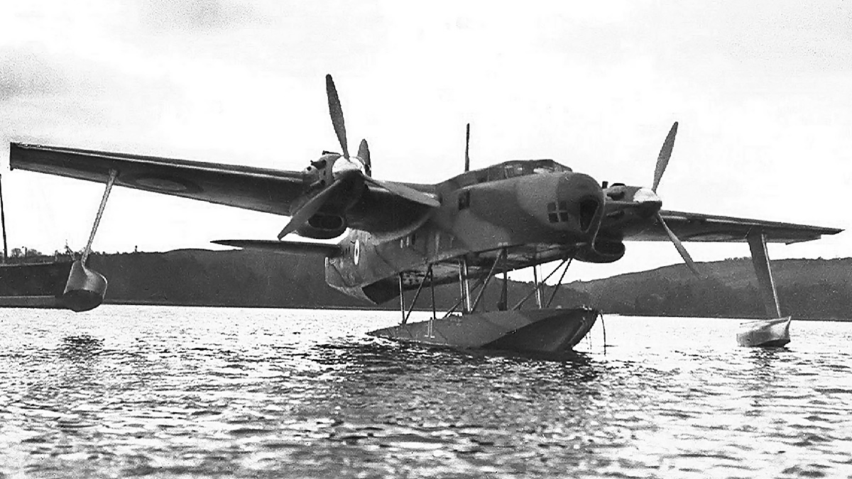
The SNCAC NC.3021 Belphégor was a high-altitude research aircraft that incorporated a pressurized cabin. Powered by a DB 610, the post-war aircraft carried a crew of three plus two researchers. It was the last aircraft design that used a Daimler-Benz doppelmotor.

The DB 613 C/D had the same compression ratio increase as the DB 610 C/D. For takeoff and emergency power at 2,900 rpm and 20.9 psi (1.44 bar) of boost, the DB 613 C/D produced 4,000 hp (2,942 kW) at sea level and 3,600 hp (2,648 kW) at 19,685 ft (6,000 m). For climb and combat power at 2,700 rpm and 19.1 psi (1.32 bar) of boost, the engine produced 3,500 hp (2,574 kW) at sea level and 3,280 hp (2,412 kW) at 19,685 ft (6,000 m). For maximum continuous power at 2,300 rpm and 17.6 psi (1.22 bar) of boost, the DB 613 C/D produced 2,850 hp (2,096 kW) at sea level and 2,860 hp (2,104 kW) at 17,388 ft (5,300 m).

The Daimler-Benz doppelmotoren represented a quick way to double an engine’s output without quite doubling the drag of installation. While the engines worked well in the He 119 and Ju 288, the engine package failed to work reliably in the He 177, which was the main application. A total of approximately 1,916 doppelmotoren were produced: 820 (544 by some sources) DB 606s, 1,070 (1,346 by some sources) DB 610s, and 26 DB 613s. The engines tested in a Junkers Ju 52 transport and powered four He 119s, 915 (1,135 by some sources) He 177s, ten Ju 288s, and one SNCAC NC.3021.

An early DB 606 A is displayed at the Technik Museum in Sinsheim, Germany. DB 610 engines are on display in Germany at the Deutsches Museum in Munich and the Luftfahrttechnisches Museum (Aviation Museum) in Rechlin; and in the United Kingdom at the Royal Air Force Cosford Museum in Shropshire and the Science Museum at Wroughton. Reportedly, a DB 610 is in France, but its location and condition have not been found. The Smithsonian National Air and Space Museum has in storage a DB 610 engine in a complete He 177 nacelle. A DB 610 combining gear reduction housing is on display at the Muzeum Lotnictwa Polskiego (Polish Aviation Museum) in Krakow, Poland. No DB 613 engines are known to have survived.

Note: The figures in this article listed as hp (horsepower) are actually PS (Pferdestärke, metric horsepower). The kW figures are converted from the PS value.

Daimler-Benz-DB-613

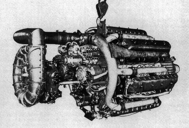
The DB 613 utilized two DB 603 engines. It was the largest, heaviest, and most powerful of the doppelmotoren. The DB 613 had an asymmetric combing gear housing that incorporated an accessory drive. The engine never progressed beyond prototype testing.

Sources:
Jane’s All the World’s Aircraft 1945-46 by Leonard Bridgman (1946)
Flugmotoren und Strahltriebwerke by Kyrill von Gersdorff, et. al. (2007)
The Secret Horsepower Race by Calum E. Douglas (2020)
Heinkel He 177 Greif by J. Richard Smith and Eddie J. Creek (2008)
Junkers Ju 288/388/488 by Karl-Heinz Regnat (2004)
Major Piston Engines of World War II by Victor Bingham (1998)
DB 606 A-B Baureihe 0 u. 1 Motoren-Handbuch by Technisches Amt (November 1942)
Ersatzteilliste für Mercedes-Benz-Flugmotor Baumust DB 606 A-B by Daimler Benz (December 1941)
DB 610 A-B Baureihe 0 u. 1 Motoren-Handbuch by Technisches Amt (November 1942)
Betriebs und Wartungsvorschrift zum Mercedes-Benz Flugmotor DB 601 A u. B by Daimler Benz (October 1940)
Motorhandbuch zum Mercedes-Benz-Flugmotor DB 603 A Baureihe 0, 1 und 2 by Daimler Benz (November 1942)

Junkers-Jumo-222-EF-front

Junkers Jumo 222 Aircraft Engine

By William Pearce

Around 1936, the RLM (Reichsluftfahrtministerium, or Germany Air Ministry) sought the design of an 1,800 hp (1,342 kW) engine for the next generation of bomber aircraft. Otto Mader, the head of the Junkers Flugzeug- und Motorenwerke AG (Junkers Aircraft and Motor Works) research institute in Dessau, considered various V and H configurations for such an engine. However, each configuration had various drawbacks. Mader discussed the engine requirements with Ferdinand Brandner and tasked him with the project. Brandner was an experienced engine and railway engineer that had recently joined Junkers.

Junkers-Jumo-222-AB-1-front

A Junkers Jumo 222 A/B-1 engine with a short gear reduction housing. First run in 1939, the Jumo 222 represented what was believed to be the next generation of German aircraft engines. Note the coolant pump below the gear reduction housing and the fuel injection pump between the intake manifolds.

Brandner and his team set a goal of 2,000 hp (1,491 kW) and immediately began designing a completely new engine. The engine originally carried the manufacturer’s designation P2001, and Junkers submitted a proposal that outlined the 1,900 hp (1,417 kW) engine to the RLM on 4 December 1936. On 4 May 1937, the RLM placed an order for a prototype P2001 engine, which would officially become the Junkers Jumo 222 on 4 April 1938. Brandner and his team continued to work on the engine design, which was finalized on 4 June 1937. Nearly from the start, the Jumo 222 was intended to power the improved development of the Junkers Ju 88 bomber, which originally carrier the manufacturer’s designation EF 73 (Entwicklungs-Flugzeug 73, Development Aircraft 73). Later, the aircraft would become the Ju 288 bomber.

The Junkers Jumo 222 was a liquid-cooled inline radial. The engine had six cylinder banks placed radially around the crankcase at 60 degree angles, with the left and right banks horizontal. Each of the six cylinder banks had four cylinders, giving the engine a total of 24 cylinders. The outer points of the six cylinder banks formed a hexagon, making the Jumo 222 one of the rare hexagonal engines, like the Curtiss H-1640 Chieftain, the Wright H-2120, the SNCM 137, and the Dobrynin series of aircraft engines.

The two-piece aluminum crankcase was split horizontally below the left and right cylinder banks. The top four cylinder banks were on the upper crankcase half, and the bottom two cylinder banks were on the lower crankcase half. The two crankcase halves were joined by 11 studs on each side and four long studs that extended from the center main bearing. The one-piece balanced crankshaft was supported in the upper crankcase half by five plain main bearings. Each main bearing cap was secured by four vertical studs and one very long stud that passed transversely through the entire crankcase. Mounted on each of the crankshaft’s four throws was a rather typical radial-engine master rod with five articulating rods. The connecting rod was split, with three articulating rods attached to the bottom and the master rod flanked by two articulated rods on the top. The two pieces of the connecting rod were joined by four bolts. Reportedly, the master connecting rods for cylinder rows 1 and 4 (front and rear) were located in bank 5 (7 o’clock position), and cylinder rows 2 and 3 (middle two) were located in bank 6 (5 o’clock position). However, a drawing of the Jumo 222 depicts a master rod in one of the upper cylinder banks. It appears the drawing shows the configuration used in early engines, and the master rods were relocated to the lower cylinder banks in later variants. The flat-top aluminum pistons were rather short with two compression rings and two oil rings, all located above the piston pin. The engine’s compression ratio was 6.5 to 1.

Junkers-Jumo-222-AB-1-rear

Rear view of the Jumo 222 A/B-1 illustrating the supercharger and its two-sided inlet. Note how the intake manifold branches to serve two adjacent cylinder banks. The engine’s magnetos are mounted to the upper cylinder banks, and the oil pump is mounted under the supercharger.

The steel cylinder barrels were installed through the crankcase and sealed at their lower end by three rubber rings. Near the bottom of each barrel was a flange with four long studs that extended up through the cylinder head. The tightening of these studs drew the barrel up into the cylinder head and sealed it with a tapered aluminum ring to the combustion chamber. The combustion chamber was wedge-shaped with the exhaust valve on the short side. The cylinder head of each bank was a single aluminum casting secured to the crankcase by 10 studs. At the top of each cylinder were two intake valves and one sodium-cooled exhaust valve. A fuel injector was positioned between the two intake valves, and a spark plug was positioned between each of the two intake valves and the common exhaust valve. The valves for each cylinder bank were actuated via rockers by a single overhead camshaft. The rear of each camshaft was driven from the crankshaft by a series of spur gears. The camshafts turned clockwise for cylinder banks 1, 3, and 5 and counterclockwise for cylinder banks 2, 4, and 6.

Attached to the front of the crankcase was a planetary gear reduction with the propeller shaft positioned at the center of the engine. While the crankshaft turned clockwise, different gear reduction housings could be used to turn the propeller in either direction. The propeller of the Jumo 222 A, C, E and G models turned counterclockwise at .368 crankshaft speed. The counterclockwise gear reduction used a fixed planetary carrier with the propeller shaft driven from the free outer ring gear. The propeller of the Jumo 222 B, D, F and H models turned clockwise at .364 crankshaft speed. The propeller shaft of the clockwise gear reduction was driven from the free planetary carrier that rotated against the fixed outer ring gear. The clockwise gear reduction on the Jumo 222 B, D, F and H models weighed approximately 66 lb (30 kg) additional. A short gear reduction housing was available, but the extended version was most common. An inertia starter was mounted to the crankcase above the gear reduction housing, and the coolant pump was mounted below the gear reduction housing.

Attached to the rear of the crankcase was an accessory housing followed by the single-stage, two-speed supercharger. The supercharger impeller was 12.8 in (325 mm) in diameter and turned at 6.70 and 9.16 times crankshaft speed in low and high gears. It provided 8.8 lb (.61 bar) of boost for takeoff. Each of the three outlets from the supercharger fed an intake pipe that branched into two manifolds. These manifolds were positioned between the cylinder Vees at the 4, 8, and 12 o’clock positions, and each fed once cylinder bank. An eight-cylinder fuel injection pump was also positioned between the intake manifolds in each of these cylinder Vees. Individual exhaust stacks were fitted to the cylinder heads between the bank Vees at the 2, 6, and 10 o’clock positions. Engine mounting pads were located on the crankcase between the bank Vees at the 2 and 10 o’clock positions.

Junkers-Jumo-222-sectional

Sectional view of the Jumo 222 with a master connecting rod in an upper cylinder bank. This is most likely a Jumo 222 A/B-1 engine, as it appears to have an early H-beam articulated connecting rod design. Later variants had the master connecting rods in the lower banks and I-bean articulated connecting rods. Note the wedge-shaped combustion chambers.

When viewed from the rear, the cylinder banks were numbered counterclockwise starting at the right horizontal bank at the 3 o’clock position, which was bank 1. Bank 2 was at 1 o’clock, bank 3 was at 11 o’clock, and so on. The front cylinder of each bank was No 1, and the rear cylinder was No 4. Each of the upper two cylinder banks had a magneto mounted to its rear. Each magneto fired all the cylinders for three banks with no redundancy. If a magneto failed, one entire side of the engine would not fire. Cylinders in opposite banks fired simultaneously. The firing order changed during the engine’s development. The following firing order is specific to the Jumo 222 E/F but may be applicable to other engine models. The Jumo 222 E/F’s firing order was as follows: Bank 2 Cylinder 1 & Bank 5 Cylinder 2, B1C1 & B4C2, B6C4 & B3C3, B2C3 & B5C4, B1C2 & B4C1, B6C2 & B3C1, B2C4 & B5C3, B1C4 & B4C3, B6C1 & B3C2, B2C2 & B5C1, B1C3 & B4C4, and B6C3 & B3C4.

The Junkers Jumo 222 A/B-1 had a 5.31 in (135 mm) bore and stroke. The engine had a total displacement of 2,830 cu in (46.38 L). The Jumo 222 A/B-1 initially produced 2,000 hp (1,491 kW) at 3,200 rpm. At the expense of reliability, further development eventually pushed its maximum power at 3,200 rpm to 2,500 hp (1,417 kW) for takeoff and 2,200 hp (1,641 kW) at 16,404 ft (5,000 m). Climbing power at 2,900 rpm was 2,260 hp (1,685 kW) at sea level and 2,090 hp (1,559 kW) at 16,404 ft. Cruising power at 2,700 rpm was 1,900 hp (1,617 kW) at sea level and 1,700 hp (1,268 kW) at 17,060 ft (5,200 m). The engine’s fuel consumption at cruise power was .477 lb/hp/hr (290 g/kW/h) at sea level. The Jumo 222 A-1 weighed 2,690 lb (1,220 kg), and the Jumo 222 B-1 weighed 2,745 lb (1,245 kg). The engine had a diameter of 3 ft 10 in (1.16 m) and was 7 ft 5 in (2.25 m) long.

In early 1938, RLM requested that the Jumo 222’s output be increased to 2,000 hp (1,491 kW). Since the engine was designed from the start for 2,000 hp (1,491 kW), this request did not present any issues, but it foreshadowed what was to come. A single-cylinder test engine was first run in March 1938, followed by one complete row of six cylinders in June 1938. On 24 April 1939, a complete Jumo 222 A/B-1 was run for the first time and taken up to 3,000 rpm. The engine was disassembled and inspected after the test and showed no signs of wear or issues.

In May 1939, Junkers submitted to the RLM design proposals for the Jumo 222-powered EF 73 (Ju 88 development) bomber aircraft. Incidentally, EF 74 was the same basic aircraft but powered by Jumo 224 engines. Encouraged by Junkers’ proposal, the RLM issued specifications in July 1939 for a new medium bomber capable of high-speeds. Originally known as Kampfflugzeug B (Warplane B), the aircraft proposal was eventually renamed Bomber B. The Bomber B specification requested an aircraft that could carry a 2,000 kg (4,410 lb) bomb load 3,600 km (2,237 mi) and have a top speed of 600 km/h (373 mph). For alternatives to the Jumo 222, the RLM requested engine designs from BMW and Daimler-Benz. The Junkers Bomber B proposal became the Ju 288, and other entrants included the Arado E.240, Focke-Wulf Fw 191, Dornier Do 317, and later, Henschel Hs 130C. The additional engine proposals were the BMW 802 18-cylinder radial and the Daimler-Benz DB 604 X-24.

Junkers-Jumo-222-Ju-52-testbed

A Jumo 222 installed in the nose of a Junkers Ju 52 transport test bed. The engine was equipped with exhaust manifolds to duct the fumes away from the cockpit. Note how the Jumo 222’s engine nacelle appears no larger than those for the Ju 52’s standard 725 hp (541 kW) engines.

The Ju 288 was selected for production, although prototypes of the Fw 191, Do 317, and Hs 130C would also be built. The Ju 288 and the Fw 191 were to be powered by the Jumo 222, which was ultimately selected over the other engines. The Jumo 222 was also planned for a future development of the Do 317. When war officially broke out on 1 September 1939, the Ju 288 was perceived as an aircraft needed for a decisive victory. It and the 2,000 hp (1,491 kW) Jumo 222 A/B-1 were given a high priority. At the time, three complete Jumo 222 A/B-1 engines were running on test stands. During 1939, Junkers had formed the Otto-Mader-Werke at Dessau to focus on engine design and development. This division was run by Mader and worked on the Jumo 222 and Jumo 004 (turbojet) engines.

In March 1940, the Jumo 222 A/B-1 achieved 2,000 hp (1,491 kW) for the first time, but some difficulties were encountered at this higher output with inadequate lubrication and connecting rod issues. Modifications were made to resolve the deficiencies, and the revised engine was running in August 1940. For flight testing, the Jumo 222 was installed in the center position of a Junkers Ju 52 trimotor transport and made its first flight on 3 November 1940. However, the Jumo 222 was not ready to be installed in the Ju 288, and the aircraft made its first flight on 29 November 1940 powered by 14-cylinder BMW 801 radial engines.

In April 1941, the Jumo 222 A/B-1 completed a 100-hour type test at 2,000 hp (1,491 kW), running at 2,860 rpm. Some of the issues during the test included spark plug damage after 60 hours, a leaking injection pump controller at 75 hours, and a camshaft bearing block failure after 88 hours. When the engine was dismantled after the test, coolant and fuel leaks were discovered, but they were not considered serious. Based on the overall positive results of the 100-hour test, the RLM ordered the Jumo 222 into production on 30 April 1941. The engine would be built at the new Flugmotorenwerke Ostmark (Aircraft Engine Factory in annexed Austria) plant under construction in Wiener Neudorf, Austria, with production expected to start on 30 August 1942. A monthly output of 1,000 engines was forecasted.

Starting in mid-1940, the RLM began to alter requirements for the Ju 288. A fourth crew member, additional equipment, and airframe changes resulted in the aircraft’s weight increasing to the point that 2,000 hp (1,491 kW) was no longer sufficient for the Ju 288 to achieve its originally-specified performance. Around mid-1941, the RLM requested that the Jumo 222 produce 2,500 hp (1,864 kW) for the Ju 288. Junkers had foreseen this request and began developing the Jumo 222 A/B-2 in 1940 to reliably produce 2,500 hp (1,864 kW) and resolve issues encountered with the early engines.

Junkers-Jumo-222-AB-installtion

A 2,000 hp (1,491 kW) Jumo 222 A/B-1 installed in a Junkers Ju 288 engine nacelle. Note the individual exhaust stacks protruding from the cowling.

The Jumo 222 A/B-2’s cylinder bore was increased .20 in (5 mm) to 5.51 in (140 mm), while its stroke remained unchanged at 5.31 in (135 mm). This change increased the Jumo 222 A/B-2’s displacement by 214 cu in (3.50 L) to 3,044 cu in (49.88 L). The H-beam articulated connecting rods of the early engines were replaced with an I-bean articulated connecting rod design. The engine’s compression ratio may have been raised to 6.735 to 1, and valve diameters may have been altered slightly. The Jumo 222 A/B-2 had a balance pipe between the intake manifolds of adjacent cylinder banks. Engine speed was limited to 2,900 rpm in an attempt to increase its reliability. The Jumo 222 A/B-2’s maximum power at 2,900 rpm was 2,500 hp (1,864 kW) for takeoff and 2,490 hp (1,857 kW) at 16,404 ft (5,000 m). Climbing power at 2,700 rpm was 2,250 hp (1,678 kW) at sea level and 2,050 hp (1,529 kW) at 16,404 ft (5,000 m). Cruising power at 2,500 rpm was 1,900 hp (1,417 kW) at sea level and 1,750 hp (1,305 kW) at 16,404 ft (5,000 m). The engine’s fuel consumption at cruise power was .449 lb/hp/hr (273 g/KW/h) at sea level.

The Jumo 222 A/B-2 was first run in mid-1941 and was taken briefly to 3,000 hp (2,237 kW) by overboosting to 11.5 psi (.79 bar) in October 1941. However, the increased bore size created a harmonic resonance within the engine. With three Ju 52s serving as Jumo 222 test beds and a number of other engines on test stands, the entire project began to encounter significant issues. Connecting rod bearings were still a problem as was corrosion of the engine’s internal components. Despite the issues, the Jumo 222A/B-1-powered Ju 288 V5 made its maiden flight on 8 October 1941. Brandner had managed to talk his way onto the aircraft for the flight, which was completed without issue. For the Ju 288, the Jumo 222 turned a four-blade Junkers VS 7 propeller that was a 13 ft 1 in (4.0 m) in diameter. An annular radiator was positioned in the cowling, and experiments were conducted on Ju 288 V5 using a ducted spinner to deliver cooling air to the radiator.

As the manufacturing plant in Austria neared completion in late October 1941, it was clear that the Jumo 222 was not going to be ready for production. A decision was made to manufacture the Daimler-Benz DB 603 at the plant with production starting in March 1942. On 24 December 1941, the RLM cancelled the Jumo 222 for the Ju 288. The decision was based on the engine’s then-current takeoff rating of only 2,000 hp (1,491 kW), its ongoing issues, and its operational readiness not being sufficient for the Ju 288’s planned production schedule. The Ju 288 would be powered by DB 610 (two coupled DB 605s) engines, and Junkers would focus on developing the Jumo 213 inverted V-12. Work on the Jumo 222 would continue, but the engine was no longer a priority. Brandner stated that, at the time, various Jumo 222 engines had completed 20 100-hour test runs, and many at Junkers felt that the engine was basically ready for production. However, further issues with the connecting rod bearings caused a developmental delay that extended from January to March 1942.

The connecting rod bearing failures took a long time to resolve with experimentation of different bearing materials and lubrication techniques. Ultimately, a new connecting rod design was employed, the antimony alloy bearing material was replaced with a tin alloy, and the synthetic engine oil used was switched to a natural oil with an increased sulfur content. Due to tin shortages, antimony had been substituted early in the engine’s development.

Junkers-Jumo-222-AB-2-3-side

A Jumo 222 A/B-2 or -3 engine with an extended gear reduction housing. Note the revised intake manifolds with a balance pipe joining the two at their center. Two engine mounting pads are visible between the upper cylinder banks.

the Jumo 222 A/B-3 was developed to cure the vibration and harmonic issues of the A/B-2 and with an improved supercharger to maintain power up to 20,997 ft (6,400 m). Along with a revised gear train, the engine incorporated all other revisions to improve reliability. The Jumo 222 A/B-3’s maximum power at 3,000 rpm was 2,500 hp (1,864 kW) for takeoff and 2,410 hp (1,797 kW) at 9,186 ft (2,800 m). Climbing power at 2,700 rpm was 2,250 hp (1,678 kW) at sea level and 1,980 hp (1,476 kW) at 20,997 ft (6,400 m). Cruising power at 2,500 rpm was 1,860 hp (1,387 kW) at sea level and 1,640 hp (1,223 kW) at 20,997 ft (6,400 m). The engine’s fuel consumption at cruise power was .463 lb/hp/hr (282 g/Kw/h) at sea level.

The Jumo 222 A/B-3 was developed quickly, and was first run in late 1941. Like the Jumo 222 A/B-2, it was briefly tested to 3,000 hp (2,237 kW) by overboosting to 11.5 psi (.79 bar) on 26 May 1942. The RLM became interested in the Jumo 222 A/B-3 and ordered it into production on 5 August 1942. Production would be undertaken at a plant in Prague in German-occupied Czechoslovakia. Optimistically, the first Jumo 222 A/B-3s were expected in October 1944 with a peak production of 1,500 engines per month achieved in September 1945. Running at 2,500 hp (1,864 kW), the Jumo 222 A/B-3 completed a 50-hour test on 9 December 1942 and a 100-hour test on 11 March 1943. The engine was tested in Ju 52s and Ju 288 aircraft, but the production plans were never realized.

The Fw 191 made its first flight in early 1942 and used BMW 801s. It was not until December 1942 that the Fw 191 V6 (third aircraft built) flew with Jumo 222 engines. With engine issues and constant changes to the underperforming bomber aircraft, the Bomber B program was cancelled in June 1943. Germany was short on resources, which were better utilized in the production of fighter aircraft rather than building troubled experimental bombers with problematic engines.

The Jumo 222 C/D was conceived in 1941 to produce 2,500–3,000 hp (1,864–2,237 kW) for high-altitude operations. The Jumo 222 C/D was designed and built with its bore increased to 5.71 in (145 mm) and its stroke increased to 5.51 in (140 mm). This gave the Jumo 222 C/D a total displacement of 3,386 cu in (55.48 L). The engine produced 3,000 hp (2,237 kW) at 3,000 rpm and could maintain much of that power up to 32,808 ft (10,000 m) thanks to an improved supercharger. Some reports indicate the Jumo 222 C/D was first run in mid-1942, but it was never given priority or considered for production until 1945, when a 3,000 hp (2,237 kW) engine was desperately needed. Apparently, two Jumo 222 C/D engines were completed, but the deteriorating war conditions shifted priorities and prevented them from being tested.

Junkers-Jumo-222-AB_Ju288_V5

The Ju 288 V5 (A-series, three-man crew) was the first of the type to fly with Jumo 222 engines. The cowling incorporated an annular radiator that was fed via a ducted spinner. Subsequent prototypes powered by Jumo 222 engines used standard spinners.

In late 1943, the Jumo 222 E/F was developed from the A/B-3 series with a 5.51 in (140 mm) bore, 5.31 in (135 mm) stroke, and 3,044 cu in (49.88 L) displacement. The engine was equipped with a two-stage, two-speed supercharger. While the primary stage of the supercharger was mechanically driven, the auxiliary stage used an infinitely variable fluid coupling. An air-to-water aftercooler was incorporated on each of the three intake pipes between the supercharger and where the pipe branched into the two intake manifolds. Coolant for the aftercooler system was circulated by a separate pump. Reports indicate that the Jumo 222 E/F had sodium-cooled intake valves and a 6.75 to 1 compression ratio.

The Jumo 222 E/F’s maximum power at 3,000 rpm was 2,500 hp (1,864 kW) for takeoff and 1,930 hp (1,439 kW) at 29,528 ft (9,000 m). Climbing power at 2,700 rpm was 2,220 hp (1,655 kW) at sea level and 1,680 hp (1,253 kW) at 36,000 ft. Cruising power at 2,500 rpm was 1,840 hp (1,372 kW) at sea level and 1,400 hp (1,044 kW) at 34,689 ft (11,000 m). The engine’s fuel consumption at cruise power was .454 lb/hp/hr (276 g/kW/h) at sea level. At 42,651 ft (13,000 m), an output of 1,710 hp (1,275 kW) at 2,900 rpm was possible with GM 1 (Göring Mischung 1 / Göring Mixture 1) nitrous oxide injection. The addition of MW 50 (Methanol-Wasser 50), a 50-50 mixture of methanol and water injected into the induction system, further boosted performance by approximately 400 hp (298 kW) up to the engine’s critical altitude. The engine was 8 ft 2 in (2.50 m) long. The Jumo 222 E weighed 3,009 lb (1,365 kg), and the Jumo 222 F weighed 3,075 lb (1,395 kg). First run in 1944, the engine initially received a high priority. However, development and plans for mass production of the Jumo 222 E/F were halted in mid-1944 to focus resources on the Jägernotprogramm (Emergency Fighter Program).

Reports indicate that the Jumo 222 E/F was flown in Ju 288 V9, and presumably it was also tested in a Ju 52. Heinkel He 219 V16 was planned to test Jumo 222 A/B-3 engines, but Jumo E/F engines were used instead when the aircraft made its first flight on 23 July 1944. Estimates indicated that the Jumo E/F-powered He 219 would be capable of 414 mph (666 km/h) at 32,808 ft (10,000 m) and 435 mph (700 km/h) with MW 50 injection at 26,247 ft (8,000 m). With the shift in priorities, He 219 V16 made less than 20 flights, and the project was abandoned by January 1945. Six Jumo 222 E/F engines were finished by war’s end, and another four were partially completed.

In early 1944, the Jumo 222 G/H (sometimes referred to as the Jumo 222 Turbo) was developed from the A/B-3 series with a 5.51 in (140 mm) bore, 5.31 in (135 mm) stroke, and 3,044 cu in (49.88 L) displacement. The engine incorporated a turbocharger and intercoolers. Running at 3,200 rpm, the Jumo G/H produced 2,400 hp (1,790 kW) for takeoff and 2,070 hp (1,544 kW) at 40,354 ft (12,300 m). At 2,900 rpm, the engine produced 1,970 hp (1,469 kW) at 41,339 ft (12,600 m). A single Jumo 222 B-2 was used as the G/H test engine and made 22 runs before the end of the war, but it was not installed in any test aircraft.

Junkers-Jumo-222-Ju-288-V9

The Ju 288 V9 (B-series, four-man crew) with standard spinners in flight. Just visible is the annular radiator mounted inside the cowling. Note the lower rows of exhaust stacks under the cowling.

On 28 April 1944, the Otto-Mader-Werke at Dessau, which was developing the Jumo aircraft engines, was heavily damaged by an Allied bombing raid. As a result, the Jumo 222 program was relocated to Oberursel near Frankfurt. These events caused major delays with all tests and engine work then in progress.

Various versions of the Jumo 222 were flown in approximately 11 aircraft: three Ju 52 test beds, six Ju 288s (V5, V6, V8, V9, V12, and V14), one Fw 191 (V6), and one He 219 (V16). Jumo 222 engines were also planned for the Heinkel He 219B and C and the Hütter Hü 211 heavy fighters. Engines were not ready for the He 219B and C airframes, and the two Hü 211 prototypes were destroyed while under construction during an Allied bombing raid in December 1944. Some sources state that Jumo 222 engines were fitted to a four-engine Heinkel He 177 (V101), as the burned out remains of this aircraft were found at Cheb in Czechoslovakia. However, examination of the aircraft reveals the engine’s exhaust stacks were in the standard four and eight o’clock positions for a Daimler-Benz DB 603 engine rather than the 2, 6, and 10 o’clock positions for the Jumo 222. The Jumo 222 was proposed for numerous other aircraft designs ranging from fighters, like the Focke-Wulf Ta 152, to bombers, like the Heinkel He 177. However, none of these plans came to fruition. A total of 289 Jumo 222 engines were built.

The Jumo 225 was conceived back in 1937 as a development of the basic Jumo 222. The Jumo 225 was a 36-cylinder engine with six banks of six cylinders. With the original 5.31 in (135 mm) bore and stroke, the Jumo 225 displaced 4,245 cu in (69.57 L). The engine was forecasted to produce 3,500–4,000 hp (2,610–2,983 kW) at 3,000 rpm and was 8 ft 10 in (2.69 m) long. The Jumo 225 was never built.

While the Jumo 222 was not trouble-free, its development progressed as well as could be hoped for considering it was a new engine design, the repeated changes to engine requirements and design, and that the ongoing war resulted in material shortages. Some contend that the changing Ju 288 and Jumo 222 requirements were intentionally made to cause the aircraft and engine to fail.

Junkers-Jumo-222-EF-left-side

The 2,500 hp (1,864 kW) Jumo 222 E displayed at the Deutsches Museum in Munich. The two-stage supercharger added to the engine’s overall length. Note the revised induction system that incorporated aftercoolers and new intake manifolds. (Deutsches Museum image)

Heinrich Koppenberg was the managing director of Junkers, the only German company producing both aircraft and aircraft engines. Koppenberg had become a powerful man who worked himself into various positions that gave him control over many strategic resources. Erhard Milch was the Air Inspector General of the Luftwaffe and in charge of aircraft production. He had gained increasing control over aircraft procurement in Germany. Milch felt that Koppenberg and Junkers would have an aircraft production monopoly and economically ruin other companies if the current Ju 288, Jumo 222, and other company projects were successful. New large-scale Junkers production orders meant that resources at other companies would be allotted to produce Junkers products under license rather than develop their own. Some contend that Milch began to alter the official requirements just as they were about to be met by Junkers. After Ernst Udet, head of the T-Amt (Technisches Amt, Technical Office of the RLM), committed suicide on 17 November 1941, Milch took his place. Milch now had the power to dictate programs for the Luftwaffe. Acting as the RLM’s authority, Milch continued to change project requirements, which left Junkers to perpetually chase the goal. Koppenberg was imprisoned in April 1942 when Junkers repeatedly failed to achieve what the RLM asked of them. While the above may be true, it is also true that the Jumo 222 had its own design issues. Brandner felt the engine was “developed to death” with its numerous displacement changes and constant design revisions.

In Spring 1944, Japan and Germany entered negotiations for Japan to purchase production rights for the Jumo 222. An agreement was reached in September 1944 that included drawings, sample parts, and the assistance of Brandner in exchange for 10 million Reichsmarks. The trip was to be made via submarine, and the departure date was set for mid-January. However, Brandner was shifted to resolve issues with the Jumo 004 turbojet in December 1944 and never went to Japan. It is not clear if Jumo 222 parts and plans were ever sent.

Brandner was captured by the Soviets at the end of the war and was interned in the USSR until 1953. While there, he worked on the M-222 engine design, which was essentially a reconstruction of the Jumo 222. Although the Soviets had captured five examples of the Jumo 222, the M-222 engine was never built. Among other projects, Brandner led a team that developed the 12,000 hp (8,948 kW) Kuznetsov NK-12 turboprop engine that powered the Tupolev Tu-95 Bear and other aircraft.

In addition to the Soviets, the United States and the British captured a number of Jumo 222 engines at the end of the war. A Jumo 222 E was built up by the United States Army Air Force at Wright Field with the intent to test the engine’s performance. While the engine was mostly complete by the end of 1946, other priorities took precedence, and the captured Jumo 222 E was never tested. Most likely, this engine was returned to Germany in 1978. It is now on display at the Deutsches Museum in Munich and is the only Jumo 222 known to exist.

Junkers-Jumo-222-EF-front

This Jumo 222 E was captured and sent to the United States for testing. It was most likely the engine that Wright Field planned to test in late 1946. The engine was returned to Germany in 1978. Note the starter mounted above the gear reduction housing. (Deutsches Museum image)

Sources:
– “The Junkers Jumo 222” by Kimble D. McCutcheon, Torque Meter Volume 6, Number 3 (Summer 2007)
Junkers Flugtriebwerke by Reinhard Müller (2006)
Flugmotoren und Strahltriebwerke by Kyrill von Gersdorff, et. al. (2007)
Ein Leben Zwischen Fronten by Ferdinand Brandner (1973)
Junkers Aircraft & Engines 1913–1945 by Antony Kay (2004)
Jane’s All the World’s Aircraft 1945/46 by Leonard Bridgman (1946)
Junkers Ju 288/388/488 by Karl-Heinz Regnat (2004)
Heinkel He 219 by R. Francis Ferguson (2020)
Dornier Do 217-317-417 An Operational Record by Manfred Griehl (1991)
http://www.enginehistory.org/Piston/Junkers/Jumo222/Jumo222.shtml
https://ww2aircraft.net/forum/threads/jumo-222-whats-the-truth.39301/
https://digital.deutsches-museum.de/item/1978-17/

Rolls-Royce-Vulture

Rolls-Royce Vulture X-24 Aircraft Engine

By William Pearce

In the mid-1930s, the British Air Ministry predicted the need for 2,000 hp (1,491 kW) engines to power new aircraft expected to enter service in the early 1940s. Rolls-Royce responded to this anticipated need with a 24-cylinder, liquid-cooled aircraft engine of an X-configuration, known as the Vulture. Initially, the Vulture design was based on utilizing four six-cylinder banks of the V-12 Kestrel engine. As the Vulture design developed, many changes were incorporated that shifted away from the Kestrel, and the Vulture ultimately had no parts in common with the Kestrel.

Rolls-Royce-Vulture

The Rolls-Royce Vulture X-24 was an attempt to create a 2,000 hp (1,491 kW) aircraft engine. A number of difficulties arose that complicated the engine’s development, leaving history to record the Vulture as a failure.

The Rolls-Royce Vulture was designed by Albert George Elliott, and its development was started in September 1935. The engine’s two-piece aluminum crankcase was split horizontally at the crankshaft’s centerline. Each crankcase half had two surfaces for mounting cylinder banks with an included angle of 90 degrees. The two crankcase halves were attached by 28 cross bolts and a series of smaller bolts along the parting flange. The cross bolts were tightened against the cylinder bank mounting surface and staggered to allow clearance for the cross bolts from the adjoining bank. Each side of the crankcase had two engine mounting pads. The single, hollow, six-throw crankshaft was secured between the two crankcase halves and supported by seven main bearings.

Each of the four monobloc cylinder banks was made of aluminum with an integral cylinder head. Steel liners were inserted for the six cylinders of each bank. Each cylinder bank was secured to the crankcase by 26 long studs that passed through to the top of the bank. The cylinder spacing was wider than that of the Kestrel to accommodate wider connecting rod bearings and to enable a future increase in bore diameter. Each cylinder had two intake valves and two sodium-cooled exhaust valves. The valves for each cylinder bank were actuated by a single overhead camshaft that was driven via bevel gears and by a vertical shaft from the gear reduction at the front of the engine.

Rolls-Royce-Vulture-rear

Rear view of the Vulture shows the coolant pumps flanking the supercharger. All of the cylinder banks were spaced at 90 degrees.

The Vulture’s connecting rod consisted of a master rod extending at a 45-degree angle from a square big end, with three articulating rods extending from the other corners of the big end. Initially, the connecting rod’s big end cap had a hinged joined on one side and was secured to the crankshaft with two bolts on the opposite side. Although different versions were tried, this configuration proved problematic and was replaced by omitting the hinge and using four bolts (two long bolts on one side and two short bolts on the other) to secure the cap to the connecting rod around the crankpin. The mating surfaces of the big end had corresponding serrations to ensure a secure fit. Incidentally, this was the same type of big end employed on the connecting rods of the Rolls-Royce Exe, the development of which had slightly proceeded that of the Vulture. When viewed from the rear of the engine, the upper right cylinder bank was designated as the ‘A’ bank, and the designations proceeded counterclockwise. The master rod served the ‘D’ bank, which was the lower right.

At the front of the engine, a spur gear on the crankshaft engaged four compound layshafts, the opposite side of which drove the propeller shaft. This compound gear reduction resulted in the propeller turning .350 times crankshaft speed and being mounted on the engine’s centerline. Viewed from the rear, the crankshaft and propeller both rotated counterclockwise. A bevel gear on the back side of each compound layshaft drove the vertical shaft for the respective cylinder bank’s camshaft. A spur gear on the rear of the crankshaft supplied power to various accessory drives and to the two-speed, single stage supercharger. The supercharger’s impeller turned at 5.464 and 7.286 times crankshaft speed in low and high gears. A coolant pump was mounted by each side of the supercharger. The engine’s compression ratio was 6.0 to 1.

Rolls-Royce-Vulture-mount

The mounting of the Vulture in the Manchester was similar to other installations—two pads on each side of the engine attached it to a tubular steel frame. The mounting pads were in the Vee formed by the upper and lower banks.

Air was drawn through the two-barrel SU carburetor and fed into the supercharger. The air/fuel mixture exited the supercharger via two outlets that respectively fed an upper or lower manifold. Each manifold was respectively positioned between the upper or lower cylinder banks. The manifold had three outlets on each side. The three outlets were connected to another manifold that was attached directly to and extended the length of the cylinder bank. The incoming charge for each cylinder was ignited by two spark plugs, one positioned in the intake side of the cylinder and the other on the exhaust side. This meant that access to the top, bottom, left, and right sides of the engine was needed to replace the spark plugs. The task was further complicated by the intake manifolds on the top and bottom and the exhaust manifolds and engine mounts on the left and right sides of the engine. Needless to say, the 24-cylinder Vulture was not a favorite with ground crews. The spark plugs were originally fired by a battery-powered coil ignition system, which was replaced by two magnetos and distributors driven from the gear reduction. The exhaust ports were on the left and right sides of the engine. A mixture of 70 percent water and 30 percent ethylene glycol was used to cool the engine.

The Vulture had a 5.00 in (127 mm) bore and a 5.50 in (140 mm) stroke. The engine’s total displacement was 2,591 cu in (42.47 L), and it had a takeoff rating of 1,800 hp (1,342 kW) at 3,200 rpm with 6 psi (.41 bar) of boost. At 3,000 rpm with 6 psi (.41 bar) of boost, the Vulture had a maximum rating of 1,845 hp (1,312 kW) at 5,000 ft (1,524 m) and 1,710 hp (1,223 kW) at 15,000 ft (4,572 m). At 2,850 rpm with 6 psi (.41 bar) of boost, the Vulture had an international rating of 1,780 hp (1,327 kW) at 4,000 ft (1,219 m) and 1,660 hp (1,237 kW) at 13,500 ft (4,115 m) and a maximum climb rating of 1,760 hp (1,312 kW) at 5,000 ft (1,524 m) and 1,640 hp (1,223 kW) at 15,000 ft (4,572 m). At 2,600 rpm with 5 psi (.34 bar) of boost, the engine had a maximum cruise rating of 1,540 hp (1,148 kW) in low gear and 1,460 hp (1,089 kW) in high gear. The Vulture was 87.2 in long, 35.8 in wide, and 42.3 in tall. The engine weighed 2,450 lb.

Rolls-Royce-Vulture-II-IV-Installation-Drawing

Installation Diagram for the Vulture II and IV engines. The main difference between the two variants was that the Vulture II drive an auxiliary gearbox via a right-angle drive mounted vertically behind the ‘A’ cylinder bank.

Preliminary testing of the Vulture engine included building an X-4 engine, and running this engine revealed the issues with the early two-bolt connecting rod design. Stresses on the bolts caused their failure, and the four-bolt connecting rod was developed. Another issue was insufficient lubrication of main bearings. The first complete 24-cylinder Vulture was run on 1 September 1937, the second in January 1938, and the third in May 1938. By November 1938, Vulture test engines had accumulated 1,150 hours of operation. Issues with the coil ignition system came to light while testing the complete engines, resulting in a switch to magnetos. In 1938, the Vulture produced 1,750 hp (1,305 kW) while on test.

Vulture engine development spanned from Mark I to Mark V. The Vulture I entered limited production and were mainly developmental engines. Refinements were incorporated into the Vulture II, which was intended for use in multi-engine aircraft. The Vulture II had a detached, five-drive, auxiliary gearbox that was driven from the engine by a flexible shaft. The flexible shaft connected to a right-angle drive mounted vertically behind the A (upper right when viewed from the rear) cylinder bank. The Vulture II was first run in September 1938. No descriptive information has been found regarding the Vulture III. The Vulture IV was nearly identical to the Vulture II but intended for single-engine aircraft. The Vulture IV had an engine-mounted three-drive auxiliary gearbox and different accessories.

The Air Ministry authorized engine production on 23 March 1939, anticipating a need for 1,560 Vultures, and true engine production started in January 1940. Issues with the Vulture necessitated a drop in its maximum speed to 3,000 rpm, but boost was increased to 9 psi (.62 bar) to maintain the engine’s takeoff rating of 1,800 hp (1,342 kW).

Hawker-Henley-K5115-Rolls-Royce-Vulture-II

The Hawker Henley testbed (K5115) was the first aircraft to fly with a Vulture engine. The large scoop under the aircraft accommodated the coolant radiator and oil cooler.

Development of the Vulture V followed that of the Vulture IV and featured additional supercharging, with an impeller that turned at 6.018 and 8.111 times crankshaft speed in low and high gears. For takeoff, the engine had a rating of 1,995 hp (1,488 kW) at 3,000 rpm with 9 psi (.62 bar) of boost. Military power at the same rpm and boost was 2,035 hp (1,517 kW) at 5,000 ft (1,524 m) and 1,840 hp (1,372 kW) at 20,250 ft (6,172 m). At 2,650 rpm and with 7 psi (.48 bar) of boost, the Vulture V had a cruise rating of 1,650 hp (1,230 kW) at 3,500 ft (1,067 m) and 1,525 hp (1,137 kW) at 17,500 ft (5,334 m).

The Hawker Henley light-bomber prototype (K5115) was converted with a Vulture engine to serve as a testbed. A ventral scoop was added to the aircraft’s bomb bay that housed the radiator and oil cooler. The cowling was modified for the Vulture with its four rows of exhaust stacks, and a scoop for the carburetor was added just forward of the cockpit. The Vulture-powered Henley was first flown on 17 April 1939, and the Vulture passed a type-test with an 1,800 hp (1,342 kW) takeoff rating in August 1939. A second Henley (L3302) was converted to a Vulture testbed and made its first Vulture-powered flight on 3 May 1940. The Vulture engine was intended for a number of aircraft under development, four of which were flown.

The Avro 679 Manchester medium bomber used two Vulture I engines and was ordered in mid-1937, before the aircraft’s design was finalized. Eventually, orders for some 700 examples were placed. The Manchester prototype (L7246) made its first flight on 24 (some sources state 25) July 1939. When Vulture II engines became available, they were used in the Manchester, and the type entered service in November 1940.

Avro-Manchester-Mk-I

A production Avro Manchester I (L7288) running up one of its Vulture engines. A shroud covered each exhaust manifold to help cool the exhaust so that the discharge did not heat the wing. The two-engine bomber was quite a handful when one of the Vultures failed, and a number of aircraft and their crew were lost due to engine issues.

The Vickers Type 284 Warwick medium bomber was originally ordered in October 1935, but a change for the first prototype (K8178) to be powered by two Vulture I engines rather than the Bristol Hercules occurred in January 1937. K8178 made its first flight on 13 August 1939, and Vulture II engines were installed in November 1940.

Two prototypes of the Hawker Tornado fighter were ordered in December 1938. The first prototype (P5219) was powered by a Vulture II engine and made its first flight on 6 October 1939. Production contracts were issued in November 1939, with the Vulture V selected as the intended powerplant. The second prototype (P5224) used a Vulture V engine and made its first flight on 7 December 1940.

The Blackburn B-20 flying boat (V8914) was ordered in 1936 and made its first flight on 26 March 1940. The experimental aircraft was powered by two Vulture II engines and featured an extendable hull and retractable wing floats. The aircraft was lost on 7 April 1940 after aileron flutter was experienced during a high-speed test flight.

In March 1941 the improved Vulture II was type tested with a takeoff rating of 2,010 hp (1,499 kW) at 3,000 rpm with 9 psi (.62 bar) of boost. At the same rpm and boost, the engine’s military power rating was 1,845 hp (1,376 kW) at 5,000 ft (1,524 m) and 1,710 hp (1,275 kW) at 15,000 ft (4,572 m). At 2,850 rpm and with 6 psi (.41 bar) of boost, the Vulture II had a normal rating of 1,780 hp (1,327 kW) at 4,000 ft (1,219 m) and 1,660 hp (1,238 kW) at 13,500 ft (4,115 m). However, the Vultures in service were taking a turn for the worse.

Vickers-Warwick-K8178-Rolls-Royce-Vulture

The Vickers Warwick prototype (K8178) was the only example of the type fitted with Vulture engines.

The Manchester’s rush into production and subsequent rush into service meant that a number of deficiencies with the airframe and serious issues with the Vulture engine were not discovered until it was too late. The engines proved to be unreliable and prone to failure. As a result, all Manchesters were grounded numerous times. Manchesters with a failed Vulture were often unable to maintain height on one engine, and about 75 percent of the time, the aircraft crashed before an emergency landing could be executed at a suitable location. A contributing factor to the Vulture’s issues was that the Battle of Britain forced Rolls-Royce to focus on the Merlin engine, which delayed Vulture development.

Some engine failures were attributed to cooling issues. One of the coolant pumps would cavitate, halting the flow of coolant to that side of the engine. The affected cylinder banks would subsequently overheat, and the engine would seize; an engine fire resulted on a number of occasions. To fix the issue, a balance tube was installed which connected the inlet of the pumps to equalize pressure between the two. The crankshaft main bearings were also prone to failure. Numerous issues resulted in the failed bearings: over-heating due to the already mentioned coolant issues, poor lubrication, ineffective bearing material, and a slight misalignment of the two crankcase halves. The Vulture’s lubrication system was reworked to prevent aeration, and a new LA4-type bearing material was adopted. The misalignment issue was solved by including locating dowels through which cross bolts passed. A dowel was positioned on each side of the main bearings between the crankcase halves. The most vexing issue was the random failure of bolts securing the connecting rod cap. This typically created cascading failures that resulted in the sudden and catastrophic loss of the engine. The issue was traced to brittle bolts, and new measures were implemented to ensure they were tightened to the new, lower toque standard to prevent excessive strain and stretching. The connecting rod was also modified slightly. In addition, the Vulture’s maximum speed was reduced again to 2,850 rpm to minimize the risk of failure. The last of these changes were detailed by Rolls-Royce under Vulture Modification No. 44. By August 1941, engines with these changes were installed in some Manchesters, and the Vulture began to reliably make it 120-hours between major inspections. In addition, Manchesters were now able to make it to an airfield on a single engine more often than not. Eventually, the time between inspections was raised to 180 hours, and the engine’s maximum takeoff speed was increased to 3,000 rpm. However, another issue with Vulture engines came to light in late 1941. Exhaust manifolds were cracking and failing, resulting in a jet of hot gasses flowing against the engine, cowling, or other internal components. The failed manifolds caused engine failures or airframe damage or both. A new manifold was designed, and all of the older units were replaced in December 1941.

Hawker-Tornado-P5224

The second Hawker Tornado prototype (P5224) with its Vulture V engine. The Vulture was relatively well-behaved during testing of the Tornado, which was very similar to the Sabre-powered Typhoon.

Even though the main problems with the Vulture were mostly resolved, engines continued to encounter various random issues, including failures, overheating, lack of power, and excessive fuel consumption. Overall, there was little faith in the Vulture engine. The Manchester itself continued to have issues, and production was halted in November 1941. Of the 202 aircraft built, approximately 33 (16.3 percent) crashed or were struck off charge due to engine failures or fires. This number does not include aircraft that were repaired after an engine failure, nor does it include the six or so aircraft lost due to propeller issues (some of which precipitated an engine failure). Tragically, also not included are the numerous Manchesters that crashed after one engine was knocked out from battle damaged only to have the “good’ engine fail after it was overstressed trying to keep the underpowered aircraft aloft. The Manchester was withdrawn from operations in mid-1942 and served in various secondary roles through 1943, when all examples were scrapped.

The Manchester was redesign to use four Merlin engines and became the Lancaster (originally Manchester III), one of the greatest World War II bombers. Production Warwicks were fitted with either Pratt & Whitney R-2800 or Bristol Centaurus engines. While around 1,760 Tornados were ordered at one point, only three Vulture-powered examples were built, and the Napier Sabre-powered Typhoon took over in place of the Tornado.

Blackburn-B-20

The Blackburn B-20 was an experimental aircraft which tested a retractable hull to improve the aerodynamics of flying boats. With a top speed of over 300 mph (483 km/h), the B-20 showed potential, but it was lost during an early test flight.

By September 1942, a Vulture engine with a contra-rotating gear reduction was installed in the sole-production Tornado (R7936). The engine and aircraft were used to test Rotol and de Havilland contra-rotating propellers. Some sources report that one Vulture engine was built with its bore increased by .4 in (10 mm) to 5.4 in (137 mm), the same as the Merlin. This increased the engine’s displacement by 432 cu in (7.08 L) to 3,023 cu in (49.54 L). However, no further information on these engines has been found.

From as early as August 1939, Rolls-Royce wanted to cancel Vulture development so that the company could focus its resources on other engines, mainly the Merlin and Griffon. However, the Air Ministry felt that it needed the Vulture engine, so development continued. Vulture development was halted in October 1941, and production ended in March 1942, with 538 engines built. The Vulture was the only X-24 aircraft engine to enter production.

Rolls-Royce had designed a number of changes to be incorporated into the Vulture engine if production had continued. The connecting rod was redesigned with the three articulated rods attached to the bearing cap, and the cap was secured to the master connecting rod via four long bolts made from improved material. The cylinder banks were redesigned to incorporate a detachable cylinder head. A lighter planetary gear reduction for the propeller would have replaced the four compound layshafts. The two-speed supercharger was redesigned to include two-stage supercharging to improve the engine’s performance at higher altitudes.

Hawker-Tornado-R7936-DH-cr-props

The sole-production Tornado (R7936) seen in 1943 with a Vulture engine turning de Havilland contra-rotating propellers. The aircraft was also used to test Rotol contra-rotating propellers.

Only a small number of Vulture engines survive, and most were recovered from Manchester wrecks. Two recovered Manchester engines (engine 1 and engine 2) are held by the Luchtoorlogmuseum (Aerial Warfare Museum) Fort Veldhuis in Heemskerk, near Amsterdam in the Netherlands. A Vulture engine from the B-20, consisting mainly of the crankshaft, connecting rods, and cylinder barrels, is displayed in the Dumfries and Galloway Aviation Museum in Scotland. Three engines are part of the Royal Air Force Museum’s collection, and all are believed to have been recovered from Manchester wrecks. One of these engines is on loan to the Rolls-Royce Heritage Trust and is displayed at the Hucknall Flight Test Museum.

Note: Many sources state that the Vulture I used an updraft carburetor, and the Vulture II and later variants used a downdraft carburetor. However, the only aircraft that appears to have had an updraft carburetor was the first Tornado prototype, which reportedly flew with a Vulture II. Early Manchesters that reportedly flew with Vulture Is appear to have downdraft carburetors. In my opinion, the most logical explanation, although still questionable, is that all Vultures had downdraft carburetors and that the early installation in the Tornado prototype that incorporated the carburetor inlet with the belly scoop was an attempt to maximize the pilot’s forward vision and minimize the number of external protuberances.

Rolls-Royce-Vulture-crash

The shattered remains of a Vulture II engine from Manchester R5779 shot down on 9 March 1942 near Oranje, Netherlands. The engine is actually on its side, and the view is of the induction manifold on the bottom of the engine. Note the severe deformation of the cylinder bank. The engine is displayed at the Luchtoorlogmuseum (Aerial Warfare Museum) Fort Veldhuis in Heemskerk. (Fort Veldhuis Airwarmuseum image)

Sources:
Major Piston Engines of World War II by Victor Bingham (1998)
The Avro Manchester: The Legend Behind the Lancaster by Robert Kirby (2015)
Rolls-Royce Piston Aero Engines – a designer remembers RRHT 16 by A. A. Rubbra (1990)
Rolls-Royce Vulture II and IV Description: Air Publication 1801A Volume I, via the Aircraft Engine Historical Society (December 1940)
Rolls-Royce Aero Engines by Bill Gunston (1989)
Aircraft Engines of the World 1945 by Paul H. Wilkinson (1945)
Hawker Aircraft since 1920 by Francis K. Mason (1991)
Avro Aircraft since 1908 by A. J. Jackson (1990)
Vickers Aircraft since 1908 by C. F. Andrews and E. B. Morgan (1988)
Blackburn Aircraft since 1909 by A. J. Jackson (1989)
https://www.key.aero/forum/historic-aviation/62280-rolls-royce-vulture-survivors

Alfa-Romeo-1101-supercharger-rear

Alfa Romeo 1101 28-Cylinder Aircraft Engine

By William Pearce

In the early 1930s, Alfa Romeo began to build aircraft engines based on foreign designs that it licensed for production. By 1938, Alfa Romeo had obtained licenses to produce the Armstrong Siddeley Lynx, Bristol Jupiter and Pegasus, De Havilland Gypsy Major and Gypsy Six, and Walter Sagitta inverted V-12. The company had also used its knowledge and experience with licensed production to design its own engines. However, Alfa Romeo’s own D-series radial engines of the early 1930s were not successful, and its 135 engine, an 18-cylinder air-cooled radial first run in 1938, suffered from reliability issues. Giustino Cattaneo had designed the 135, but he left Alfa Romeo in 1936, before the first engine was built. Still, the design of these original Alfa Romeo engines owed much to the foreign engines built under license.

Alfa-Romeo-1101-supercharger-rear

The Alfa Romeo 1101 28-cylinder engine with its remote, two-speed supercharger. Note the induction system from the supercharger to the cylinders. The fuel injection pump and magnetos can be seen on the back of the engine. One cylinder bank has a seemingly restrictive exhaust manifold attached.

In 1938, Ugo Gobbato, Managing Director of Alfa Romeo, tasked the Special Studies Service (Servizio Studi Speciali / SSS) to design an entirely new aircraft engine. The SSS was Alfa Romeo’s secret or special projects department. Wifredo Ricart, a Spaniard who escaped his country’s civil war and fled to Italy in 1936, was in charge of the new engine’s design, which was designated 281.

The 281 was an inline radial that consisted of seven cylinder banks, each with four cylinders. The liquid-cooled engine was equipped with a single-speed, single-stage centrifugal supercharger. The 281 engine had a 4.72 in (120 mm) bore, a 4.33 in (110 mm) stroke, and displaced 2,126 cu in (34.83 L). With the bore larger than the stroke, the oversquare engine was designed have a relatively small diameter and operate at higher rpm. The engine had an estimated output of 1,480 hp (1,089 kW) at 3,000 rpm. The 281 was designed with then-current power requirements in mind, but did not consider future demands for power increases. The 281 design produced basically the same power as the 135, although it was 35 in (.88 m) in diameter compared to 55 in (1.40 m) for the 135. Realizing that a more powerful engine was needed, Ettore Pagani, also of the SSS, completed a design study in 1939 of an enlarged 281 to produce an excess of 2,000 hp (1,471 kW). This engine became known as the 1101. The 281 was never built.

The Alfa Romeo 1101 was initially designated 101, but it was also referred to as the 1.101 and 1.1.01. However, 1101 has become the most common designation. The design team for the 1101 consisted of Ricart, Orazio Satta, and Giuseppe Busso. The engine had a cast aluminum crankcase with seven cylinder banks mounted radially around its center and spaced at 51.4 degrees. The upper cylinder bank extended vertically from the crankcase. Each cylinder bank contained four cylinders and was made from cast aluminum with an integral cylinder head. Wet cylinder liners made of nitrided steel were installed in the cylinder block. Each cylinder had one intake valve and one sodium-cooled exhaust valve. The intake valve was 2.56 in (65 mm) in diameter, and the exhaust valve was 2.20 in (56 mm) in diameter. The valves for each cylinder bank were actuated via hydraulic tappets by a single overhead camshaft. The camshaft was driven by bevel gears and a vertical shaft from the front of the engine. The one-piece crankshaft was supported by five main bearings. The pistons for each row of cylinders were served by a master connecting rod with six articulated connecting rods. The cylinders had a compression ratio of 6.5 to 1.

Alfa-Romeo-1101-front

Front view of the 1101 illustrates the vertical drives for the camshafts. The four mounts on the front of the gear reduction are visible. A sump is positioned between the two lower cylinder banks.

Mounted to the front of the engine was a propeller gear reduction. Via planetary bevel gears, the propeller shaft rotated at .400 times crankshaft speed. Mounted to the rear of the engine were two fuel injection pumps and two magnetos. The primary injection pump had a maximum flow of 423 gallons (1,600 L) per hour and delivered fuel to the injectors mounted in the intake side of the cylinder head. The secondary fuel injection pump had a maximum flow of 132 gallons (500 L) per hour and delivered methanol (methyl alcohol) to injectors located in the intake manifold just before the intake port of each cylinder. The methanol was used to increase maximum power and reduce detonation. Each of the two magnetos fired one of the two spark plugs mounted in each cylinder.

A shaft extending from the rear of the engine powered a remote, two-speed, centrifugal supercharger. The 1101 engine as built did not have a supercharger mounted in a housing that attached directly to the rear of the crankcase. Some sources indicate that the engine had a two-stage supercharger, but photos show just the remote supercharger with no other stage apparent. Two-stage supercharging was certainly planned for future versions of the 1101 engine. Air entered the back of the supercharger, where it was compressed to provide 11.4 psi (.78 bar) of boost. A duct extending from the supercharger was intended to incorporate an aftercooler, but surviving photos do not show one installed. From the duct, the air entered a semi-annular manifold located at the rear of the engine. Seven individual runners extended from the semi-annular manifold and connected to each cylinder bank. The runners had four outlets grouped in two pairs of two and mounted to the left side of the cylinder bank. Each cylinder bank had four exhaust ports on its right side, and the exhaust ports for the middle two cylinders of each bank were grouped together.

A centrifugal water pump, most likely mounted to the lower rear of the engine, flowed coolant at 14,530 gallons (55,000 L) per hour. The coolant was a mix of 70 percent water and 30 percent ethylene glycol. Double dynafocal engine mounts were located on the back side of each cylinder bank. The propeller gear reduction housing also had four mounts.

The engine was officially designated Alfa Romeo 1101 RC37/87. The “RC” stood for Riduttore de giri (gear reduction) and Compressore (supercharged), and 37/87 designated the critical altitudes (in hectometers) at which maximum continuous power was obtained with its two-speed supercharger. The engine had a 5.31 in (135 mm) bore and a 4.92 in (125 mm) stroke. This gave the 1101 a displacement of 3,057 cu in (50.10 L). However, since the strokes of the articulated rods were slightly longer than that of the master rod, the engine had an actual displacement of 3,066 cu in (50.25 L). Takeoff power was 2,200 hp (1,618 kW) at 2,625 rpm. For one minute at emergency power and 2,800 rpm, the engine produced 2,300 hp (1,692 kW) at 7,546 ft (2,300 m) in low gear and 2,150 hp (1,581 kW) at 26,247 ft (8,000 m) in high gear. For five minutes at military power and 2,700 rpm, the engine produced 2,000 hp (1,471 kW) at 10,827 ft (3,300 m) in low gear and 1,900 hp (1,398 kW) at 28,215 ft (8,600 m) in high gear. Maximum continuous power was achieved at 2,625 rpm, with the engine producing 1,850 hp (1,361 kW) at 12,139 ft (3,700 m) in low gear and 1,750 hp (1,287 kW) at 28,543 ft (8,700 m) in high gear. The 1101 had a diameter of 44.7 in (1.14 m) and was 97.2 in (2.47 m) long. The engine weighed 2,535 lb (1,150 kg) without accessories.

Alfa-Romeo-1101-supercharger-side

The 1101’s aftercooler was to be incorporated into the induction pipe between the supercharger and the ring manifold. Note the shaft housing extending back from the engine to power the supercharger.

The 1101 was designed and built at Alfa Romeo’s plant in Pomigliano d’Arco, near Naples, Italy. As the 1101 was being built, Italy had secured licenses from Germany to build the Daimler-Benz DB 601 and DB 605 engines and tasked Alfa Romeo with their production. This led to the formation in 1941 of Alfa Romeo Avio, a division focused solely on producing aircraft engines. The 1101 engine was completed in late December 1941 and first run in early January 1942. Under tests, the 1101 experienced detonation issues that damaged the pistons and cylinder heads. These issues were caused by the 87 octane fuel and the timing of the fuel injection system.

Development of the engine progressed until early 1943, when the war situation required the dispersal of factories away from populated areas. The 1101 engine project was moved to Armeno in northern Italy, near the Swiss border. The move caused delays, but the entire project was suspended on 8 September 1943, following news of the Italian armistice. The Armeno plant housing the 1101 fell in the territory controlled by the newly formed Italian Social Republic (Repubblica Sociale Italiana), which was mostly controlled by Germany. It is not clear if work on the 1101 engine was resumed or stayed suspended, but by mid-1943, the Armeno plant housed nearly all of the engine’s documentation, the prototype engines, and parts for approximately 20 pre-production examples. On 18 June 1944, all of the materiel in the Armento plant was destroyed by Italian partisans (resistance fighters) to prevent its use by the German military.

Future development of the 1101 included two-stage supercharging to increase the engine’s military power rating to 2,300 hp (1,692 kW). Most likely, this configuration would include an additional centrifugal supercharger incorporated in a housing mounted directly to the rear of the crankcase and mechanically driven from the crankshaft. Investigations were also conducted into turbocompounding the engine. The turbocompounded 1101 would utilize five turbines. Three turbines would be positioned at the front of the engine to recover power from the exhaust and feed it back to the propeller shaft. The remaining two turbines were turbosuperchargers (first stage of supercharging) positioned at the rear of the engine to feed air into the engine’s centrifugal supercharger (second stage of supercharging). The turbocompounded engine was expected to weight 20 percent more, increase fuel efficiency by 15 percent, and produce 2,600 (1,912 kW) hp. However, no such engines were built.

Alfa-Romeo-1101-test-side

The 1101 mounted on what appears to be a test bed. This image gives a good view to the spacing of the intake and exhaust ports. Note the two dynafocal mounts on the back of each cylinder bank. It is not clear if the remote supercharger has been omitted or is just obscured by the mounting frame.

Other developments included enlarging the engine’s cylinder, possibly with a 5.71 in (145 mm) bore and a 5.12 in (130 mm) stroke, so that total displacement was 3,668 cu in (60.1 L). Studies were also undertaken to create a 42-cylinder engine by having six cylinders per bank. Some sources indicate that this engine had a displacement of approximately 4,270 cu in (70 L). However, the bore and stroke of the 1101 would displace 4,586 cu in (75.1 L) with 42 cylinders. Therefore, the bore and stroke of the 4,270 cu in (70 L) 42-cylinder engine are not known.

The 1101 was proposed for at least three aircraft projects: the Alfa Romeo 1902—apparently a development of the Aeronautica Umbra MB-902 design, with the two engines buried in the fuselage and driving propellers on each wing via extension shafts and right-angle drives; the Caproni Vizzola MCT (Monoposto Caccia Trigona / Tr.1207)—a single seat fighter of a taildragger configuration with the engine buried in the fuselage behind the cockpit and driving a tractor propeller via an extension shaft; and the Savoia-Marchetti SM-96 (II)—a single seat taildragger fighter of a conventional tractor layout with the engine installed in the nose. None of these projects were built.

Two Alfa Romeo marine engines utilized 1101 components: the inline, four-cylinder 1001 engine used a single cylinder bank, and the V-8 1002 engine used two cylinder banks. Both of these engines were built during World War II and neither appear to have entered quantity production. The only known part of an 1101 engine to survive is a fuel injection pump stored at the Alfa Romeo Museum (Museo Storico Alfa Romeo) in Arese, Italy.

Note: The horsepower (hp) figures in this article are actually Cavalli Vapore (CV), which is 1.387% more than a standard hp (100 CV = 98.6 hp). The kilowatt (kW) values are based on CV.

Caproni-Vizzola-MCT-Alfa-Romeo-1101

A composite drawing of the Caproni Vizzola MCT (Monoposto Caccia Trigona / single seat fighter, designed by Emmanuele Trigona) with the 1101 engine installed in the fuselage.

Sources:
– “Destini incrociati” by Luigi Montanari, epocAuto Anno 14, N.1 (January 2019)
– “Le attività aeronautiche in Alfa Romeo fino al 1945” by Fabio Morlacchi, L’Alfa Romeo di Ugo Gobbato 1933-1945, Monografi AISA 92 (2 April 2011)
https://it.wikipedia.org/wiki/Alfa_Romeo_1101
https://www.secretprojects.co.uk/threads/alfa-1101.5117/
https://www.secretprojects.co.uk/threads/savoia-marchetti-sm-96-ii.7636/

Napier-Sabre-VA-front

Napier H-24 Sabre Aircraft Engine

By William Pearce

Aircraft engine designer Frank Bernard Halford believed that an engine using a multitude of small cylinders running at a relatively high rpm would be smaller, lighter, and just as powerful as an engine with fewer, large cylinders running at a lower rpm. Halford was contracted by the British engineering firm D. Napier & Son (Napier) in 1928 and built the Rapier I (E93) in 1929 and the Dagger I (E98) in 1933. Both of these air-cooled engines had a vertical H configuration, with the Rapier having 16-cylinders and the Dagger having 24-cylinders. Ultimately, the 539 cu in (8.83 L) Rapier VI (possibly E106) produced 395 hp (295 kW) at 4,000 rpm in 1936, and the 1,027 cu in (16.84 L) Dagger VIII (E110) produced 1,000 hp (746 kw) at 4,200 rpm in 1938.

Napier-Sabre-VA-front

The Napier Sabre’s block-like exterior hid the engine’s complicated internals of 24-cylinders, two crankshafts, sleeve-valves, and numerous drives. The Sabre VA seen here was the last variant to reach quantity production. (Napier/NPHT/IMechE image)

Back around 1930, Napier Chairman Montague Stanley Napier and the company’s Board of Directors sought to diversify into the diesel aircraft engine field. Montague Napier and Bill Nowlan laid out the design for a liquid-cooled, vertical H, 24-cylinder diesel engine that used sleeve valves. Given the Napier designation E101, the engine had a 5.0 in (127 mm) bore, a 4.75 in (121 mm) stroke, and a total displacement of 2,239 cu in (36.68 L). Montague Napier passed away on 22 January 1931, but Nowlan continued design work under the direction of George Shakespeare Wilkinson, Ronald Whitehair Vigers, and Ernest Chatterton. Wilkinson took out a patent for the sleeve drive (GB363850, application dated 7 January 1931), and Vigers took out patents for sealing rings on a plug-type cylinder head (GB390610, application dated 15 February 1932) and sleeve-valves (GB408768, application dated 24 January 1933). It appears the E101 diesel was abandoned around 1933. However, two- and six-cylinder test engines had been built to test the sleeve-drive mechanism and prove the validity of the entire design.

In 1935, Halford joined Napier’s Board of Directors, acting as the company’s Technical Director. Halford was disappointed that the Rapier and Dagger were not more successful. He decided to design a new, larger, 24-cylinder, H-configuration engine that would be capable of 2,000 hp (1,491 kW). The design for at least part of the new engine was based on the E101 diesel. As he had done with the Rapier, Halford showed his design to George Purvis Bulman, the Deputy Director of Engine Research and Development for the British Air Ministry. Bulman was aware that designers of fighter aircraft were interested in such an engine and was able to arrange financial support for Napier to develop the H-24 engine. Halford’s 2,000 hp (1,491 kW) engine was given the Napier designation E107 and became known as the Sabre.

Serious design work on the Sabre started in 1936. The spark-ignition engine had a similar layout to the E101 diesel—both being liquid-cooled H-24s with sleeve-valves and possessing the same bore and stroke. Liquid-cooling was selected to efficiently reject the heat that the compact 2,000 hp (1,491 kW) engine generated, and a mixture of 70 percent water and 30 percent ethylene-glycol would be used. The Air Ministry enabled the free flow of information between Napier, Halford, and Harry Ralph Ricardo—a British engine expert who had been researching sleeve-valve engines for quite some time. With the engine technology known in the early 1930s, a perception existed that the poppet-valve engine had reached its developmental peak. Sleeve-valves were seen as a way to extract more power out of internal combustion engines. The sleeve-valve offered large, unobstructed intake and exhaust ports, a definite advantage to achieve a full charge into the cylinder and complete scavenging of the exhaust when the engine is operating at high RPMs.

Napier-Sabre-II-Cutaway

A drawing of a Sabre II, which was the main production variant. Note the two-sided supercharger impeller and the location of the supercharger clutch at the rear of the engine. The design of these components was changed for the Sabre IV and later variants. All accessories are mounted neatly atop the engine, away from any leaking oil, coolant, and fuel. (AEHS image)

The layout of the engine was finalized as a horizontal H-24. The Napier Sabre had a two-piece aluminum crankcase that was split vertically on the engine’s centerline. Sandwiched between the crankcase halves was an upper and lower crankshaft, each secured by seven main bearings. The center main bearing was larger than the rest, which resulted in an increased distance between the third and fourth cylinders in each bank. The crankshafts were phased at 180 degrees, and a cylinder for each crankshaft fired simultaneously. The single-piece, six-throw crankshafts were identical, and both rotated counterclockwise when viewed from the rear of the engine. Fork-and-blade connecting rods were used, with the forked rods serving the three front-left and three rear-right cylinders of the upper banks and the three front-right and three rear-left cylinders of the lower banks.

A 21-tooth spur gear on the front of each crankshaft meshed with two compound reduction gears, each with 31 teeth. A 17-tooth helical gear on the opposite side of each of the four compound reduction gears drove the 42-tooth propeller shaft counterclockwise. The drive setup created a double gear reduction, with the compound reduction gears operating at .6774 times crankshaft speed and the propeller shaft operating at .4048 times the speed of the compound reduction gears. The final gear reduction of the propeller shaft was .2742 crankshaft speed. A balance beam was mounted to the front of the two upper and the two lower compound reduction gears. A volute spring acted on each side of the beam to equally balance the tooth loading of the helical reduction gears on the propeller shaft. The forward ends of the compound reduction gears were supported by a gear carrier plate that was sandwiched between the crankshaft and the propeller shaft housing. The propeller shaft, balance beams, and volute springs were secured by the propeller shaft housing that bolted to the front of the engine.

Napier-Sabre-Sleeve-Drive-Cutaway

Sectional view through a Sabre cylinder block showing the upper and lower cylinders paired by the sleeve-valve drive. Intake and exhaust passageways were cast into the cylinder block, and coolant flowed through the hollow cylinder head. Note that the sleeve extends quite a distance between the cylinder head and cylinder wall. Also note the supercharger torsion bar extending through the hollow sleeve-valve drive shaft. (AEHS image)

Attached to each side of the crankcase was a one-piece, aluminum cylinder block that consisted of an upper and a lower cylinder bank, each with six cylinders. With the exception of a few installed studs, the left and right cylinder blocks were interchangeable. A two-piece sleeve-valve drive shaft was mounted between each cylinder block and the crankcase, and it ran between the upper and lower cylinder banks. Each sleeve-valve drive shaft was driven at crankshaft speed through a layshaft by an upper compound reduction gear. The left and right sleeve-valve drive shafts each had six worm gears with 11 teeth, and each worm gear drove the sleeves for an upper and a lower cylinder pair via a 22-tooth worm wheel made from bronze. This setup enabled the sleeves to operate at half crankshaft speed (and half the speed of the sleeve-valve drive shaft). The worm wheels and their separate housings were mounted to the inner sides of the cylinder blocks. Each worm wheel had an upper and lower sleeve crank, which were phased at 180 degrees. Each sleeve crank drove a sleeve via a ball joint mounted on a lug on the outer bottom of the sleeve. The rotational movement of the sleeve crank caused the sleeve to reciprocate and oscillate in the cylinder bore. In addition, when the sleeve for the upper cylinder was rotating clockwise, the sleeve for the paired lower cylinder rotated counterclockwise. Due to the opposite rotation, the sleeves for the upper and lower cylinder banks had different (mirrored) port shapes. Each sleeve-valve drive shaft was supported by 14 bearings, with each of the six worm wheel housings incorporating two bearings.

Each sleeve-valve drive shaft was hollow and had a supercharger torsion bar running through its center. The two supercharger torsion bars acted on a compound supercharger gear at the rear of the engine. Via a fluid-actuated clutch, the two-speed supercharger was driven at 4.48 times crankshaft speed in low gear (often called moderate supercharging, MS) and 6.62 times crankshaft speed in high gear (often called full supercharging, FS). The supercharger’s centrifugal impeller was double-sided. Air was drawn in through a four-barrel updraft SU (Skinner’s Union) suction carburetor and fed into the impeller. The air and fuel mixture was distributed from the supercharger housing via one of four outlets to a cast aluminum manifold that ran along the outer side of each cylinder bank.

When ports in the sleeve-valve aligned with three intake ports cast into the cylinder, the air and fuel mixture was admitted into the cylinder. As the sleeve rotated and ascended, the ports closed. Two spark plugs mounted parallel to one another in the cylinder head ignited the mixture, initiating the power stroke. As the sleeve rotated back and descended, the cylinder’s two exhaust ports were uncovered to allow the gasses to escape between the upper and lower cylinder banks. The sleeve’s stroke was approximately 2.5 in (64 mm), and its full rotation was approximately 56 degrees (its rotary movement being approximately 28 degrees back and forth from center). Each sleeve had only four ports, one of which was used for both intake and exhaust. Valve timing had the intake ports opening 40 degrees before top dead center and closing 65 degrees after bottom dead center. The exhaust ports opened 65 degrees before bottom dead center and closed 40 degrees after top dead center. Intake and exhaust ports were simultaneously partially uncovered for 80 degrees of crankshaft rotation—the last 40 degrees of the exhaust stroke and the first 40 degrees of the intake stroke. Twelve exhaust ports were located in a single line on each side of the engine, and each ejector exhaust stack served two ports—one for an upper cylinder and one for a lower cylinder.

Napier-Sabre-parts

A Sabre engine being assembled. In the foreground are the individual cylinder heads with their sealing rings. In the row above the heads is a long, slim shaft that is the supercharger torsion bar. It passes through the two-piece sleeve-valve drive shaft. Further right are six sleeve-valve cranks, followed by their housings, and a set of 12 sleeves. The crank end of the sleeve is up, and note the helical grooves for oil control. Next is a row of pistons sitting inverted, each with rings and a piston pin. On the next row is a crankshaft being worked on and a set of six fork-and-blade connecting rods. Further to the right is another set of connecting rods that are already attached to the other crankshaft (out of frame). The lady furthest from the camera is working on the four compound reduction gears that will take power from the two crankshafts and deliver it to the propeller shaft, which is being held in a wooden fixture in front of her. On the far left, behind the ladies, is a Sabre cylinder block with numerous studs to attach the cylinder bank. Next is an upper accessory housing with some accessories attached. Last is a lower accessory housing with fuel, water (both external), and oil (internal) pumps.

The forged aluminum pistons were rather short with a minimal skirt, which was required for the engine’s relatively short stroke, use of sleeve-valves, and narrow width. Each flat-top piston had two compression rings above the piston pin, with one oil scraper ring below. The top ring was later tapered to prevent the buildup of carbon. The piston operated directly in the sleeve-valve, which was .09375 in (2.4 mm) thick and made from forged chrome-molybdenum steel. When the piston was at the bottom of its stroke, it was almost completely removed from the cylinder and supported only by the sleeve. The sleeves had a hardened belt on their inner diameter at the top of the piston stroke. Helical grooves inside the lower part of the sleeve helped prevent excessive oil accumulation on the sleeve walls. Oil was controlled further by an oil scraper fitted at the bottom of the sleeve between its outer diameter and the cylinder. The top of each cylinder was sealed by a cast aluminum cylinder head. The cylinder head acted as a plug atop the cylinder and was sealed against the sleeve by a compression ring. The top of the sleeve extended between the cylinder head and the cylinder wall. The cylinder head incorporated coolant passages that communicated with passages in the cylinder block. The engine had a compression ratio of 7.0 to 1.

The upper and lower crankshafts also respectively drove upper and lower auxiliary drive shafts. These auxiliary drive shafts were contained in their own separate housings which were respectively attached to the upper and lower sides of the assembled engine. The upper auxiliary drive shaft powered a vacuum pump, the propeller governor, two distributors, two magnetos, a generator, an air compressor, a hydraulic pump, and an oil pump for the supercharger. All of this equipment was mounted as compactly as possible to the top of the engine. The lower auxiliary drive shaft powered left and right coolant pumps, a fuel pump, and various oil pumps. The coolant and fuel pumps were mounted below the engine, while the oil pumps were internal. The coolant pumps provided a combined flow of 367 US gpm (306 Imp gpm / 1,389 L/min). Also mounted atop the engine and geared to the rear of the upper crankshaft was the Coffman combustion starter unit. The starter had a five-cartridge capacity.

The upper and lower cylinders were numbered 1–12, starting from the left rear and proceeding clockwise to the right rear. With the simultaneous firing of a cylinder for each crankshaft, the engine’s firing order was Top 1/Bottom 6, T9/B10, T5/B2, T12/B7, T3/B4, T8/B11, T6/B1, T10/B9, T2/B5, T7/B12, T4/B3, and T11/B8. Four mounting pads on the underside of the engine attached it to the support structure in the aircraft. The basic design of the Sabre enabled easy access for routine maintenance. Once the aircraft’s cowling was removed, crews had unobstructed access to all of the spark plugs on the sides of the engine and all accessories mounted atop the engine.

Napier-Sabre-IIB-Service-Typhoon-IB

A Sabre IIB being pulled from a Typhoon IB. Note the coolant header tank at the front of the engine, the accessories packaged atop the engine, the two-into-one exhaust stacks, and the hydraulic supercharger clutch at the rear of the engine. The cylinder housing for the five-cartridge Coffman starter can be seen above the supercharger.

The Napier Sabre I (E107) engine had a 5.0 in (127 mm) bore and a 4.75 in (121 mm) stroke. With a bore diameter greater than the stroke length, the Sabre was an over-square engine. Each cylinder displaced 93.2 cu in (1.53 L), and the engine’s total displacement was 2,239 cu in (36.68 L). At 3,700 rpm, the Sabre I produced 2,050 hp (1,529 kW) at 2,500 ft (762 m) with 7 psi (.48 bar) of boost and 1,870 hp (1,394 kW) at 14,500 ft (4,420 m) with 8 psi (.55 bar) of boost. The engine was 81.1 in (2.06 m) long, 40.0 in (1.02 m) wide, and 51.1 in (1.30 m) tall. The Sabre I weighed 2,360 lb (1,070 kg).

Sabre development at Napier’s works in Acton, England progressed quickly, and single-, twin-, and six-cylinder test engines were all running by the end of 1936. The first of four 24-cylinder prototype engines was run on 23 November 1937, and the Air Ministry ordered six additional test engines by December. On 17 January 1938, the Sabre passed initial acceptance tests with a rating of 1,350 hp (1,007 kW), and on 3 March, the Air Ministry ordered two Sabre-powered Hawker Typhoon fighter prototypes. Also in March, the engine passed a 50-hour test that included a peak output of 2,050 hp (1,529 kW). All ordered engines were completed by the end of 1938 and were running on test stands by February 1939. While testing continued, the Sabre I was first flown in a Fairey Battle on 31 May 1939, piloted by Chris Staniland. As installed in the Battle, the Sabre had a single exhaust manifold on each side of the engine that collected the exhaust from all 12 cylinders.

In July 1939, the Air Ministry ordered 100 production engines and material for another 100 engines. In August, the Sabre passed a type test with a rating of 1,800 hp (1,342 kW). On 8 October 1939, an order for 250 Typhoons was placed, and on 24 February 1940, the Typhoon prototype (P5212) made its first flight, piloted by Philip G. Lucas. Three four-into-one exhaust manifolds were originally installed on each side of the Typhoon’s Sabre, but these were quickly replaced by what would become the standard two-into-one exhaust stacks. In March 1940, Napier created its Flight Development Establishment at Luton, England for flight testing the Sabre and developing installations for the engine. By all accounts, the Sabre continued to perform well, although some vibration issues were experienced with the Typhoon. In June 1940, the engine passed a 100-hour type test with a maximum output of 2,050 hp (1,529 kW) at 3,700 rpm, making the Sabre the first engine to have a service rating over 2,000 hp (1,491 kW).

Fairey-Battle-Napier-Sabre-I-and-Folland-Fo108-Sabre-II

The installation of Sabre engines on the Fairly Battle (top) and Folland F.108 (bottom) were well executed. Two Battles and three Fo.108s were employed to test the Sabre, and these aircraft provided valuable information about the engine.

Since mid-1938, a plan was underway to use an uprated Sabre engine in a specially-designed aircraft for a speed record attempt. The special engine produced 2,450 hp (1,827 kW) at 3,800 rpm with 9.2 psi (.63 bar) of boost and was first run on 6 December 1939. Installed in the Napier-Heston Racer, the combination first flew on 12 June 1940, piloted by G. L. G. Richmond. Difficulties with the new engine and airframe resulted in a hard landing that damaged the aircraft beyond repair. The Sabre engine installed in the Napier-Heston Racer featured two six-into-one exhaust manifolds on each side of the engine.

Around November 1939, the Air Ministry ordered 500 examples of the Typhoon. This order was temporarily suspended due to the Battle of Britain but was reinstated in October 1940. At that time, Napier began work to produce additional Sabre engines for the Typhoon order, but production was still a very limited affair. These early engines were limited to 25 hours before being removed for major inspection. The first production Typhoon IA (R7576) flew on 27 May 1941, with other aircraft soon to follow. Nearly all Sabre I engines were used in Typhoon IAs.

Around 1940, consideration was given to producing the Sabre in the United States. A Sabre I was sent to the Army Air Corps Technical Branch at Wright Field, Ohio, where it was inspected by a number of aircraft engine and automotive manufacturers in early 1941. While the engine was judged to be impressive overall, the general consensus was that the Sabre’s complexity and its unproven sleeve-valves made it too much of a risk to justify production in the United States.

Hawker-Typhoon-IB-Napier-Sabre

With its 14 ft (4.27 m) three-blade propeller turning, this early Typhoon IB warms up its Sabre engine for a flight. The Typhoon IB had four 20 mm cannons, while the earlier IA had 12 .303 machine guns. At the center of the radiator is the open carburetor intake, which was later covered by a momentum air filter. Note the underwing identification/invasion stripes.

Napier continued to develop the engine as the Sabre II, and the first production Sabre II was completed in January 1941. The Sabre II produced 2,090 hp (1,559 kW) at 3,700 rpm at 4,000 ft (1,219 m) with 7 psi (.48 bar) of boost and 1,735 hp (1,294 kW) at 17,000 ft (5,182 m). Sabre II engines were first installed in Typhoons on a trial basis in June 1941, and the engine was cleared for 50 hours between major inspections around this time. The Sabre II would ultimately replace the Sabre I in Typhoon IAs and IBs, and the Sabre I was phased out around October 1941. In addition to the Typhoon, the Sabre II also powered the Martin-Baker MB3 fighter, which made its first flight on 31 August 1942, and the Hawker Tempest V fighter prototype (HM595), which made its first flight on 2 September 1942, piloted by Lucas. The Tempest V was a new aircraft developed from the Typhoon.

The Folland Fo.108 was built to Air Ministry Specification 43/37 calling for an engine testbed aircraft. Three of the fixed-gear monoplanes were delivered to Napier’s Flight Development Establishment at Luton in 1941 and were initially fitted with Sabre II engines. The aircraft were to serve Napier for several years testing various versions of the Sabre engine. One of the Sabre-powered aircraft was lost on 14 September 1944.

The Sabre III was similar to the II but was intended for higher engine speeds. The Sabre III was selected for the Blackburn B-37 Firebrand carrier strike aircraft. At 4,000 rpm, the Sabre III had a takeoff rating of 2,250 hp (1,678 kW) and military ratings of 2,310 hp (1,723 kW) at 2,500 ft (762 m) with 9 psi (.62 bar) of boost and 1,920 hp (1,432 kW) at 16,000 ft (4,877 m). At 3,500 rpm, the engine had a normal rating of 1,890 hp (1,409 kW) at 5,000 ft (1,524 m) and 1,630 hp (1,215 kW) at 16,500 ft (5,029 m). The Firebrand (DD804) was first flown on 27 February 1942. However, with production priority going to the Typhoon, the Ministry of Aircraft Production decided to reengine the Firebrand with the Bristol Centaurus sleeve-valve radial engine. Only around 24 of the Sabre-powered versions were built.

Blackburn-Firebrand-I-Napier-Sabre

The Blackburn Firebrand, was to be powered by the Sabre III. However, Sabre engine production was allocated to the Typhoon, and the Firebrand was reengined with the Bristol Centaurus. Pictured is DD815, the third Firebrand Mk I prototype.

With production engines in production airframes, Sabre reliability issues were soon encountered. After running for a few hours, sometimes not even passing initial tests, Sabre engines began to experience excessive oil consumption and sleeve-valves cracking, breaking, seizing or otherwise failing. Examinations of numerous engines found sleeves distorted or damaged. Since the Sabre’s main application was the Typhoon, it was that aircraft that suffered the most. To make matters worse, the Typhoon was experiencing its own issues with in-flight structural failures. Other aircraft suffered as well. On 12 September 1942, the Sabre II engine in the MB3 failed; the subsequent crash landing destroyed the prototype and killed the pilot, Valentine H. Baker.

The Sabre had performed admirably during testing, but the production engines were encountering issues at an alarming rate. The early engines were built and assembled by hand. Parts with small variances were matched to obtain the desired clearances and operation. This was a luxury that could not be afforded once the engine was mass produced. The sleeves were found to be .008 to .010 in (.203 to .254 mm) out of round. This caused the cascading failure of other components as the engine was operated. In addition, the piston was forming a ridge in the sleeve, leading to excessive wear and the eventual failure of the piston rings, piston, or sleeve.

Carbon build-up was causing issues with the lubrication system. While in flight, aeration of the oil resulted in a heavy mist of oil flowing from the breather and coating the cockpit, obscuring the pilot’s view. The Coffman cartridge starter caused other issues; its sudden jolt when starting the engine occasionally damaged sleeve-drive components, setting up their inevitable failure. Part of the starting issue was that the sudden rotation of the engine with a rich mixture washed away the oil film between the pistons and sleeves. Finally, service crews were misadjusting the boost controller, creating an over-boost situation that led to detonation in the cylinders and damaged engines.

Hawker-Tempest-I-Napier-Sabre-IV

The Tempest I was powered by the Sabre IV engine. At 472 mph (760 km/h), the aircraft was the fastest of the Tempest line. The Tempest I was rather elegant without the large chin radiator, and the wing radiators were similar to those that would be used on the Sabre VII-powered Fury.

Napier worked diligently to resolve the issues. A detergent-type oil was used to prevent the build up of carbon on internal components. A centrifugal oil separator was designed to deaerate the oil and was fitted to Sabre engines already installed in Typhoons. Changes were made to the starter drive, and a priming mixture of 70 percent fuel and 30 percent oil was utilized to maintain an oil film in the cylinders. The boost controllers were factory sealed, and severe repercussions were put in place for their unauthorized tampering.

The issues with sleeve distortion were the most serious and vexing. Methods were devised to measure the sleeve with special instruments via the spark plug hole. While this helped to prevent failures, it also caused the withdrawal of low-time engines as sleeves became distorted. To fix the issue, different sleeve materials were tried along with different processes of manufacture, but nothing seemed to work. The supply of Sabre engines fell behind the production of Typhoon aircraft, and engineless airframes sat useless at manufacturing facilities. The engine shortage was so severe that a good Sabre would be installed in a Typhoon to ferry the aircraft to a dispersal facility. The engine would then be removed, returned to the aircraft factory, and installed in another Typhoon to shuttle that aircraft away, repeating the process over and over.

In October 1941, Francis Rodwell ‘Rod’ Banks replaced Bulman, who was, at the time, the Director of Engine Production for the Ministry of Aircraft Production. Bulman was back in Engine Research and Development and continued to work with Halford and Napier to resolve issues with the Sabre. Banks suggested that Napier work with the Bristol Engine Company on a suitable sleeve for the Sabre. Bristol had been manufacturing radial sleeve-valve engines since 1932, and their Taurus engine had the same 5.0 in (127 mm) bore as the Sabre. Napier was apparently not interested in pursuing that possible solution, so Banks went directly to Bristol and had them machine a pair of sleeves for use in the Sabre two-cylinder test engine. The Bristol sleeves were made from centrifugally cast austenitic steel comprised of nickel, chromium, and manganese. The sleeve was nitrided to increase its hardness and was not more than .0002 in (.005 mm) out of round. The Sabre two-cylinder test engine with the Bristol sleeves ran 120 hours without issue. Banks then had Bristol produce 48 sleeves for two complete 24-cylinder Sabre test engines. Bristol became unhappy with sharing its components and processes with a competitor, and Napier was still hesitant to utilize Bristol’s materials and techniques. Bristol’s position is somewhat understandable considering it took them years and a sizable fortune to develop the materials and procedures to reliably manufacture their sleeves.

Napier-Sabre-VA-rear

The Sabre VA had a one-sided supercharger impeller, a relocated supercharger clutch, and a two-barrel injection carburetor. These refinements were introduced on the Sabre IV. The Sabre VA powered the Tempest VI. (Napier/NPHT/IMechE image)

With the Air Ministry’s push, Napier was taken over by English Electric in December 1942. The new management was happy to accept any assistance from Bristol, and Bristol was now more willing than ever to lend support. A lack of support from the Napier board of directors had caused Halford to give a three-month notice of resignation, and he left in early 1943 to focus on turbojet engines at the de Havilland Engine Company. Halford was already involved in turbojet engine development at de Havilland before his departure from Napier, and some accused him of neglecting his duties on the Sabre. However, it was the Ministry of Aircraft Production that had previously asked him to get involved with the turbojet. Halford continued consulting work on the Sabre for a time. Before his departure from Napier, Halford’s Sabre designs had progressed up to the Sabre V. Ernest Chatterton took over Sabre development after Halford’s departure. Through all this, Bulman continued to work with Napier, but the Ministry of Aircraft Production handed all responsibility for the Sabre engine to Banks in early 1943. To get engine production up to speed, Sundstrand centerless grinders made in the United States and destined for a Pratt & Whitney factory producing R-2800 C engines were rerouted to Napier’s Sabre production facility in Liverpool. While it is not entirely clear how Banks felt at the time, he later wondered what would have become of the Fairey Monarch H-24 engine if the Air Ministry and the Ministry of Aircraft Production had encouraged its development with the same financial and technological resources supplied for the Sabre.

In the spring of 1943, some 1,250 engines had accumulated a total of 12,000 hours of testing and 40,000 hours of service use, and the Sabre’s service life was extended from 25 hours to 250 hours between major inspections. With Sabre reliability issues resolved and production resuming, development of the engine continued. The Sabre IV incorporated a two-barrel Hobson-RAE injection carburetor and a revised supercharger with a single-sided impeller. The supercharger clutches were updated and relocated from the extreme rear of the supercharger to between the supercharger and the engine. Revised gears turned the impeller at 4.68 times crankshaft speed in low gear and 5.83 times crankshaft speed in high gear. The Sabre IV produced 2,240 hp (1,670kW) at 4,000 rpm at 8,000 ft (2,438 m) with 9 psi (.62 bar) of boost. The engine was selected for the Tempest I, the prototype of which was initially ordered on 18 November 1941, followed by an order for 400 production aircraft in August 1942. The Tempest I featured a streamlined nose and its radiator and oil cooler were installed in the wing’s leading edge. The prototype Tempest I (HM599) was first flown on 24 February 1943, piloted by Lucas, and would go on to record a speed of 472 mph (760 km/h) at 18,000 ft (5,486 m) in September 1943. However, delays and development issues with the Sabre IV engine led to the Tempest I order being converted to Sabre IIA and IIB-powered Tempest Vs.

The Sabre IIA (E115) was a refinement of the Sabre II and had been developed in mid-1943. The engine had a modified oil system and used dynamically-balanced crankshafts. The Sabre IIA had a takeoff rating of 1,995 hp (1,488 kW) at 3,750 rpm with 7 psi (.48 bar) of boost. At 3,750 rpm and 9 psi (.62 bar) of boost, the engine had a military rating of 2,235 hp (1,667 kW) at 2,500 ft (762 m) and 1,880 hp (1,402 m) at 15,250 ft (4,648 m). At 3,700 rpm and 7 psi (.48 bar) of boost, the engine had a normal rating of 2,065 hp (1,540 kW) at 4,750 ft (1,448 m) and 1,735 hp (1,294 kW) at 17,000 ft (5,182 m). Fuel consumption at cruise power was .46 lb/hp/hr (280 g/kW/h). Starting around August 1943, Sabre IIA engines were incorporated into production Typhoon IB and Tempest V Series I aircraft.

Napier-Sabre-VA-cutaway

Cutaway drawing of a Sabre VA illustrating the engine’s propeller reduction gears and sleeve-valve drive. Note the upper and lower accessory drives, the slight fore-and-aft angling of the spark plugs, and the single-sided supercharger impeller. (Napier/NPHT/IMechE images)

In 1944, prototypes of the Sabre IIB (E107A) became available. Compared to the Sabre IIA, the IIB used a different carburetor, had a modified boost controller, and was cleared for additional engine speed. The Sabre IIB had a takeoff rating of 2,010 hp (1,499 kW) at 3,850 rpm with 7 psi (.48 bar) of boost. At 3,850 rpm with 11 psi (.76 bar) of boost, the engine had a military rating of 2,400 hp (1,790 kW) at sea level, 2,615 hp (1,950 kW) at 2,500 ft (762 m), and 2,045 hp (1,525 kW) at 13,750 ft (4,191 m). The Sabre IIB had the same normal rating as the IIA. The engine was used in later Typhoon IBs and was the main Sabre version to power the Tempest V Series II.

The Sabre IIC (E107B) was a similar to the IIB but with new supercharger gears. The impeller turned at 4.73 times crankshaft speed in low gear and at 6.26 times crankshaft speed in high gear. The engine had a takeoff rating of 2,065 hp (1,540 kW) at 3,850 rpm. At the same engine speed and with 11 psi (.76 bar) of boost, the military power rating was 2,400 hp (1,790 kW) at 2,000 ft (610 m) and 2,045 hp (1,525 kW) at 13,750 ft (4,191 m). The Sabre IIC was used in some late production examples of the Tempest V, including those converted as target tugs in 1948.

The Sabre V (E107C) was developed from the IV with an updated carburetor. Linkages were incorporated to allow one lever to control the engine’s throttle and the propeller’s pitch along with automatic boost and mixture control, but this system could be overridden by the pilot. The spark plugs were repositioned, although it is not clear if this change was made on the Sabre V or the Sabre VA engine. Rather than being parallel, as in earlier Sabre engines, the electrode of the front spark plug was angled forward, and the electrode of the rear spark plug was angled back. The engine produced 2,420 hp (1,805 kW) at 3,750 rpm at 4,250 ft (1,295 m) with 15 psi (1.0 bar) of boost. The Sabre V was tested in the Tempest I, and the combination was first flown on 8 February 1944 by Bill Humble. On 12 February, an order for 700 Sabre V-powered Tempest Is was issued. This order was later reduced to 300 examples, and then converted to the Sabre V-powered Tempest VI in May. The prototype Tempest VI (HM595 again) made its first flight on 9 May 1944, piloted by Humble. Cooling the more powerful engine in warmer climates required modifications to be incorporated into the Tempest VI, including a larger chin radiator and a secondary oil cooler in the wing. Carburetor inlets were also relocated to the wing’s leading edge. Otherwise, the aircraft was similar to the Tempest V.

Hawker-Tempest-V-and-VI-Napier-Sabre-IIA-and-VA

A Tempest V Series I (top) and Tempest VI (bottom). The Tempest V Series I had Hispano Mk II cannons with long barrels that protruded from the wing’s leading edge. The Tempest V Series II and other Tempests had Hispano Mk V cannons with short barrels. The Sabre VA-powered Tempest VI (bottom) has an enlarged chin radiator, an oil cooler in the wing, and carburetor inlets in both wing roots.

The Sabre VA was essentially the production version of the Sabre V. The Sabre VA had a takeoff rating of 2,300 hp (1,715 kW) at 3,850 rpm with 12 psi (.83 bar) of boost. The engine’s military rating at 3,850 rpm with 15 psi (1.0 bar) of boost was 2,600 hp (1,939 kW) at 2,500 ft (762 m) and 2,300 hp (1,715 kW) at 13,750 ft (4,191 m). At 3,650 rpm, the Sabre VA had a normal rating of 2,165 hp (1,614 kW) at 6,750 ft (2,057 m) and 1,930 hp (1,439 kW) at 18,000 ft (5,486 m). Cruise power at 3,250 rpm was 1,715 hp (1,279 kW) at 6,750 ft (2,057 m) and 1,565 hp (1,167 kW) at 14,250 ft (4,343 m). Fuel consumption at cruise power was .50 lb/hp/hr (304 g/kW/h). The engine was 82.2 in (2.10 m) long, 40.0 in (1.02 m) wide, and 46.0 in (1.17 m) tall. The Sabre VA weighed 2,500 lb (1,134 kg). Starting around March 1946, the engine was the powerplant for production Tempest VI aircraft.

The Sabre VI was the same engine as the Sabre VA, but it incorporated an annular nose radiator and provisions for a cooling fan, all packaged in a tight-fitting cowling. The cooling fan rotated clockwise, the opposite direction from the propeller. The intent of the engine and cooling system combination was to produce a complete low-drag installation package that would cool the engine sufficiently for use in tropical climates. The radiator incorporated cooling elements for both engine coolant and oil.

Hawker-Tempest-V-Napier-Sabre-IIB-ducted-spinner

The Sabre VI incorporated an annular radiator and provisions for an engine-driven cooling fan. Tempest V NV768 was used to test a number of different spinner and annular radiator cowling configurations with the Sabre VI. The aircraft is seen here with a large ducted spinner. The configuration slightly improved NV768’s performance over that of a standard Tempest. (Napier/NPHT/IMechE image)

Napier and Hawker experimented with annular radiators using various Sabre IIB engines installed on a Typhoon IB (R8694) and a Tempest V (EJ518). In early 1945, the Sabre VI with an annular radiator was test flown on a Tempest V (NV768). Numerous changes to the annular radiator and its cowling eventually led to the development of a ducted spinner, which was installed on NV768. The aircraft continued to test annular radiators through 1948. While the annular radiator added 180 lb (82 kg), it created only a third of the drag compared to the chin radiator, decreased the aircraft’s overall drag by almost nine percent, and improved the Tempest’s top speed by 12 mph (19 km/h). The annular radiator’s durability was inadvertently tested on 18 December 1944 when EJ518 made a forced, gear-up landing after a hydraulic failure. The annular radiator was undamaged and later installed on NV768. The chin radiator was typically destroyed during a gear-up landing.

Two Sabre VI engines, each with an annular radiator and a cooling fan, were installed on a Vickers Warwick C Mk III (HG248) twin-engine transport. With the Sabre engines, the Warwick’s top speed was limited to 300 mph (483 km/h) due to its fabric covering. This was still about 75 mph (121 km/h) faster than the aircraft’s original design speed. Most of the annular radiator testing was conducted at Napier’s Flight Development Establishment at Luton. While some of the ducted spinner research was applied to the Napier Naiad turboprop, none of the work was applied to production piston engines.

Napier-Sabre-VI-Vickers-Warwick-CIII

A Vickers Warwick C Mk III (HG248) was used to test the installation of the Sabre VI engine with an annular radiator and an engine-driven cooling fan. Note that the fan rotates in the opposite direction from the propeller and that the lower cowling folds down level to be used as a work platform. The rear four exhaust ejectors were replaced with elongated stacks to prevent excessive heat build-up on the wing’s leading edge. (Napier/NPHT/IMechE image)

The Sabre VII carried the Napier designation E121 and was essentially a VA engine strengthened to endure higher outputs. The engine was fitted with water/methanol (anti-detonant) injection that sprayed into the supercharger via an annular manifold. The mixture used was 40 percent water and 60 percent methanol. The water/methanol injection lowered the engine’s tendency toward detonation and allowed for more power to be produced. The supercharger housing was reworked for the water/methanol injection, and the cylinder heads were modified to accommodate two compression rings. Individual ejector exhaust stacks were fitted, replacing the two-into-one stacks previously used on most Sabre engines.

Initially, the Sabre VII had a takeoff rating of 3,000 hp (2,237 kW) at 3,850 rpm with water/methanol injection and 17.25 psi (1.19 bar) of boost. This was later increased to 3,500 hp (2,610 kW) at the same rpm with 20 psi (1.38 bar) of boost. The engine’s military rating at 3,850 rpm with 17.25 psi (1.19 bar) of boost and water/methanol injection was 3,055 hp (2,278 kW) at 2,500 ft (762 m) and 2,820 hp (2,103 kW) at 12,500 ft (3,810 m). The water/methanol injection flow rate was 76 US gph (66 Imp gph / 300 L/h) at takeoff, 78 US gph (65 Imp gph / 295 L/h) at military power in low supercharger, and 122 US gph (102 Imp gph / 464 L/h) at military power with high supercharger. The water/methanol flow rates corresponded to 30 percent of the fuel flow at low supercharger and 45 percent of the fuel flow at high supercharger. The Sabre VII’s fuel flow was 284 US gph (235 Imp gph / 1,068 L/h) at takeoff, 287 US gph (239 Imp gph / 1,087 L/h) at military power in low supercharger, and 289 US gph (241 Imp gph / 1,096 L/h) at military power with high supercharger. At 3,700 rpm and 10.5 psi (.73 bar) of boost, the Sabre VII had a normal rating of 2,235 hp (1,667 kW) at 8,500 ft (2,591 m) and 1,975 hp (1,473 kW) at 18,250 ft (5,563 m). Cruise power at 3,250 rpm was 1,750 hp (1,305 kW) at 8,500 ft (2,591 m) for a fuel consumption of .45 lb/hp/hr (274 g/kW/h), and 1,600 hp (1,193 kW) at 17,000 ft (5,182 m) for a fuel consumption of .51 lb/hp/hr (310 g/kW/h). The engine was 83.0 in (2.11 m) long, 40.0 in (1.02 m) wide, and 47.2 in (1.20 m) tall. The Sabre VII weighed 2,540 lb (1,152 kg). Some sources state that a Sabre VII engine achieved an output of 4,000 hp (2,983 kW) and was run at 3,750 hp (2,796 kW) for a prolonged period without issues during testing.

Napier-Sabre-VII-rear

A Sabre VII with its revised supercharger housing that accommodated water/methanol injection. The injection controller is mounted just above the supercharger housing. The Sabre VII ultimately produced 3,500 hp (2,610 kW) at 3,850 rpm with 20 psi (1.38 bar) of boost. (Napier/NPHT/IMechE image)

The Sabre VII was intended to power the Hawker Fury Mk I, of which 200 were ordered in August 1944. Shifting priorities at the end of the war all but cancelled the aircraft, and only two prototypes were built. The first prototype (LA610) made its initial Sabre VII-powered flight on 3 April 1946. This aircraft would go on to record a speed of 483 mph (777 km/h) at 18,500 ft (5,639 m) and 422 mph (679 km/h) at sea level. The Sabre VII was also test-flown on a Tempest V or VI in mid-1946, but additional details have not been found. This aircraft had the larger radiator and wing root carburetor inlets of the Tempest VI, but it did not have the additional oil cooler in the wing.

The Sabre VIII carried the Napier designation E122 and was based on the Sabre VII. The engine incorporated contra-rotating propellers and a two-stage supercharger. Four aftercoolers were to be installed—one on each induction runner leading from the supercharger housing to the intake manifold attached to the cylinder bank. Although some sources say the Sabre VIII was built, it appears to have remained an unbuilt project. The engine was forecasted to have a military rating of 3,350 hp (2,498 kW) and be capable of 25 psi (1.72 bar) of boost.

Hawker-Fury-I-Napier-Sabre-VII

The Napier Sabre VII engine installed in the nearly-complete Hawker Fury Mk I prototype. The aircraft and engine combination created a fast and elegant fighter. Note the leading edge wing radiators. (Napier/NPHT/IMechE image)

Production of the Sabre was halted shortly after the end of World War II with approximately 5,000 engines produced. Starting in October 1939, Napier worked to establish a shadow factory in Liverpool to produce Sabre engines. The first engine, a Sabre II, was completed at this factory in February 1942. The Liverpool site manufactured around 3,500 II, IIA, IIB, and VA engines, with the remaining 1,500 engines, including all prototypes, coming from Napier’s Acton works. With Sabre development at an end, Napier focused on their next aircraft engine, the two-stroke diesel/turbine compounded Nomad.

A number of engine designs based on the Sabre were considered, but most stayed as projects, and none progressed beyond cylinder testing. The E109 of 1939 was half of a Sabre, with 12-cylinders and a single crankshaft. It would have displaced 1,119 cu in (18.34 L). The E113 of 1940 was a fuel-injected, two-stroke, uniflow, Sabre-type test engine intended for increased engine speed and boost. The design concept originated with Harry Ricardo, and a two-cylinder test engine was built in 1942. Reportedly, the test engine was so loud that people on the street had to cover their ears as they passed by Napier’s works in Acton. The E120 of 1942 was a 32-cylinder Sabre consisting of four banks of eight cylinders. It would have displaced 2,985 cu in (48.91 L). The E123 of 1943 was a complete 24-cylinder, fuel-injected, two-stroke Sabre based on the E113 test engine. It had a forecasted output of 4,000 hp (2,983 kW) but was never built.

Although the Sabre was proposed for many projects that never left the drawing board and powered a few prototypes, the engine’s main applications were the 109 Typhoon IAs, 3,208 Typhoon IBs, 801 Tempest Vs, and 142 Tempest VIs produced during World War II. After the initial production difficulties, which were quite severe, the engine served with distinction. The Sabre could be difficult to start, and it was advisable to use a remote heater to pre-heat the coolant and oil in cold temperatures. Sleeve trouble came back with Typhoons stationed around Normandy, France in the summer of 1944. Fine dust particles from the soil were getting into the engines and causing excessive sleeve wear. A momentum air filter developed by Napier cured the trouble. The filter was designed and test flown the same day of its original request, and all the Typhoons in France were fitted with a filter within a week. Production of the Sabre was an expensive affair, with each horsepower costing four to five times that of the Rolls-Royce Merlin. However, Typhoons and Tempests played an important role in attacking German forces on the ground and countering V-1 flying bombs. Around a dozen Sabre engines survive and are on display in museums or held in private collections. As of 2020, there are no running Sabre engines, but efforts are underway to create running examples to power Typhoon and Tempest aircraft under restoration.

Napier-Sabre-E122

General arrangement drawing of the unbuilt Sabre VIII (E122). The engine featured a two-stage supercharger and contra-rotating propellers. It was forecasted to produce 3,350 hp (2,498 kW).

Sources:
Major Piston Aero Engines of World War II by Victor Bingham (2001)
Allied Aircraft Piston Engines of World War II by Graham White (1995)
Aircraft Engines Volume Two by A. W. Judge (1947)
By Precision Into Power by Alan Vessey (2007)
An Account of Partnership – Industry, Government and the Aero Engine by George Bulman and edited by Mike Neale (2002)
I Kept no Diary by F. R. (Rod) Banks (1978)
Boxkite to Jet — the remarkable career of Frank B Halford by Douglas R Taylor (1999)
The Napier Way by Bryan ‘Bob’ Boyle (2000)
The Hawker Typhoon and Tempest by Francis K. Mason (1988)
Hawker Typhoon, Tempest and Sea Fury by Kev Darling (2003)
Tempest: Hawker’s Outstanding Piston-Engined Fighter by Tony Buttler (2011)
Hawker Aircraft since 1920 by Francis K. Mason (1991)
Blackburn Aircraft since 1909 by A. J. Jackson (1968/1989)
Aircraft Engines of the World 1945 by Paul H. Wilkinson (1945)
Aircraft Engines of the World 1946 by Paul H. Wilkinson (1946)
Aircraft Engines of the World 1949 by Paul H. Wilkinson (1949)
– “The Napier Sabre Engine Parts 1–3” by J. A. Oates, Aircraft Production Volume 6, Numbers 66–68 (April–June 1944) via The Aircraft Engine Historical Society
– “Napier Sabre II” by F. C. Sheffield, Flight (23 March 1944)
– “Napier Sabre VII” Flight (22 November 1945)
– “Napier Flight Development” Flight (25 July 1946)
Jane’s All the World’s Aircraft 1945/46 by Leonard Bridgman (1946)
Jane’s All the World’s Aircraft 1947 by Leonard Bridgman (1947)
Jane’s All the World’s Aircraft 1948 by Leonard Bridgman (1948)

Mitsubishi-Ha-43-NASM-TF

Mitsubishi [Ha-43] (A20 / Ha-211 / MK9) Aircraft Engine

By William Pearce

In 1916, the Internal Combustion Engine Section, Machinery Works (Nainenki-ka Zokisho) of the Mitsubishi Shipbuilding Company Ltd (Mitsubishi Zosen KK) was formed to build aircraft engines. A number of licenses to build engines in Japan were acquired from various European engine manufacturers. Initially, the engines were of the Vee type. The aircraft engine works was renamed Mitsubishi Aircraft Company Ltd (Mitsubishi Hokuki KK) in 1928. In the late 1920s, licenses were acquired to produce the five-cylinder Armstrong Siddeley Mongoose and the nine-cylinder Pratt & Whitney R-1690 Hornet air-cooled radial engines.

Mitsubishi-Ha-43-front-and-left

Front and side views of the Mitsubishi [Ha-43] (A/20 / Ha-211 / MK9). The engine performed well but was underdeveloped. Its development and production were slowed by bombing raids and materiel shortages. The engine powered two of Japan’s best next-generation fighters, the A7M2 and Ki-83. While the aircraft were excellent, the war was already lost.

In 1929, Mitsubishi built the first aircraft engine of its own design. Carrying the Mitsubishi designation A1, the engine was a two-row, 14-cylinder, air-cooled radial of 700 hp (522 kW). This engine was followed in 1930 by the A2, a 320 hp (237 kW) nine-cylinder radial. A larger 600 hp (477 kW) nine-cylinder engine, the A3, was also built the same year. None of these early engines were particularly successful, and only a small number were built: one A1, 14 A2s, and one A3. However, Mitsubishi learned many valuable lessons that it applied to its next engine, the A4 Kinsei.

The two-row, 14-cylinder A4 was developed in 1932 and was initially rated at 650 hp (485 kW). The A4 had a 5.51 in (140 mm) bore, a 5.91 in (150 mm) stroke, and a total displacement of 1,973 cu in (32.33 L). In 1934, Mitsubishi consolidated its subsidiaries and became Mitsubishi Heavy Industries Ltd (Mitsubishi Jukogyo KK). Also in 1934, an upgraded version of the A4 engine was developed as the 830 hp (619 kW) A8 Kinsei. The Kinsei was under continual development through World War II, and numerous versions of the engine were produced. Ultimately, the last variants were capable of 1,500 hp (1,119 kW), and production of all Kinsei engines totaled approximately 15,325 units.

In mid-1941, Mitsubishi began work on an 18-cylinder engine that carried the company designation A20. The engine was intended to be lightweight and produce 2,200 hp (1,641 kW). The A20 design was developed from the Kinsei, although the 18-cylinder A20 really only shared its bore and stroke with the 14-cylinder engine—it is not even clear if the pistons were interchangeable. The team at Mitsubishi designing the A20 engine were Kazuo Sasaki—main engine section; Kazuo Inoue, Ding Kakuda, and Mitsukuni Kada—supercharger and auxiliary equipment; Katsukawa Kurokawa—propeller gear reduction; Shigeta Aso—engine cooling; Shuichi Sugihara—fuel injection system, and Shin Nakano—turbosupercharger. The A20 eventually carried the Imperial Japanese Army (IJA) designation Ha-211, the Imperial Japanese Navy (IJN) designation MK9, and the joint designation [Ha-43]. For simplicity, the joint designation will primarily be used. However, few sources agree on the engine’s various sub-type designations, and there is some doubt regarding their accuracy.

Tachikawa-Ki-94-I-mockup

The mockup of the Tachikawa Ki-94-I illustrated the aircraft unorthodox configuration. With its two [Ha-43] engines, the fighter had an estimated top speed of 485 mph (781 km/h). However, its complexity led to its cancellation and the pursuit of a more conventional design.

The Mitsubishi [Ha-43] had two rows of nine cylinders mounted to an aluminum crankcase. The crankcase was formed by three sections. Each section was split vertically through the centerline of a cylinder row, with the middle section split between both the front and rear cylinder rows. Each crankshaft section contained a main bearing to support the built-up, three-piece crankshaft. An additional main bearing was contained in the front accessory drive. The cylinders were made up of a steel barrel screwed and shrunk into a cast aluminum head. Each cylinder had one intake valve and one sodium-cooled exhaust valve. The valves were actuated by separate rockers and pushrods. Unlike the Kinsei engine, the [Ha-43] did not have all of its pushrods at the front of the engine. The [Ha-43] had a front cam ring that drove the pushrods for the front cylinders, and a rear cam ring that did the same for the rear cylinders. When viewed from the rear, the cylinder’s intake port was on the right side, and the exhaust port was on the left. Sheet metal baffles attached to the cylinder head helped direct the flow of cooling air through the cylinder’s fins. Cylinder numbering proceeded clockwise around the engine when viewed from the rear. The vertical cylinder atop the second row was No. 1 Rear, and the inverted cylinder under the front row was No. 1 Front.

At the front of the engine was the propeller gear reduction and the magneto drive. Planetary gear reduction turned the propeller shaft clockwise at .472 times crankshaft speed. Each of the two magnetos mounted atop the gear reduction fired one of the two spark plugs mounted in each cylinder. One spark plug was located on the front side of the cylinder and the other was on the rear side. A 14-blade cooling fan was driven by the propeller shaft and mounted in front of the gear reduction. Not all [Ha-43] engines had a cooling fan. At the rear of the engine was an accessory and supercharger section. The single-stage, two-speed, centrifugal supercharger was mechanically driven by the crankshaft. Individual intake runners extended from the supercharger housing to each cylinder. The intake and exhaust from the front cylinders passed between the rear cylinders, with the exhaust running above the intake runners. The supercharger’s inlet was directly behind the second row of cylinder. Behind the inlet was a fuel distribution pump that directed fuel to an injector installed by the inlet port of each cylinder.

The 18-cylinder [Ha-43] had a 5.51 in (140 mm) bore a 5.91 in (150 mm) stroke, and displaced 2,536 cu in (41.56 L). The basic engine with its 7.0 to 1 compression ratio and single-stage, two-speed supercharger produced 2,200 hp (1,641 kW) at 2,900 rpm and 10.1 psi (.69 bar) of boost for takeoff. Military power was 2,050 hp (1,527 kW) at 3,281 ft (1,000 m) in low gear and 1,820 hp (1,357 kW) at 21,654 ft (6,600 m) in high gear. Both power ratings were produced at 2,800 rpm and 8.1 psi (.56 bar) of boost. Anti-detonation (water) injection was available, but it is not clear at what point it was used—most likely for military power and above. The engine was 48 in (1.23 m) in diameter, 82 in (2.09 m) long, and weighed 2,161 lb (980 kg).

Tachikawa-Ki-74

The high-altitude Tachikawa Ki-74 was built around a pressure cabin for high-altitude flight. The aircraft most likely has [Ha-43] engines with a 14-blade cooling fan. The [Ha-42] engine had a 10-blade cooling fan. The exhaust from the turbosupercharger can be seen on the right side of the image.

[Ha-43] design work was completed in October 1941. The first engine was built at the Mitsubishi No. 2 Engine Works (Mitsubishi Dai Ni Hatsudoki Seisakusho), which was located in Nagoya and developed experimental engines, and was finished in February 1942. As the [Ha-43] was being tested, Mitsubishi proposed in April 1942 to use the engine for its new A7M fighter. The first [Ha-43] engine for the IJA was completed in August 1942. In September 1942, the IJN selected the 2,000 hp (1,491 kW) Nakajima [Ha-45] engine for the A7M1 and many of its other high-powered fighter projects under development. This setback inevitably slowed development of the [Ha-43]. At the time, there were no applications for the engine, with the IJA feeling it was too powerful and the IJN selecting the Nakajima engine. Two more [Ha-43] engines, one each for the IJA and IJN were completed in November 1942.

Mitsubishi continued development at a slow pace, hampered in part by difficulties with designing turbine wheels for the engine’s remote turbosupercharger. It was not until June 1943 that the [Ha-43] passed operational tests and began to be selected for installation on several aircraft types and not just projects. The first [Ha-43]-powered aircraft to fly was the third prototype of the Tachikawa Ki-70. The Ki-70 was a twin-engine reconnaissance aircraft with a glazed nose and twin tails. Originally powered by two 1,900 hp (1,417 kW) Mitsubishi [Ha-42] engines, the aircraft’s performance was lacking, and the third prototype was built with two turbosupercharged [Ha-43] 12 (IJA Ha-211-IRu) engines. The [Ha-43] 12 produced 2,200 hp (1,641 kW) for takeoff; 1,930 hp (1,439 kW) at 16,404 ft (5,000 m); and 1,750 hp (1,305 kW) at 31,170 ft (9,500 m). First flying in late 1943, the [Ha-43] 12-powered aircraft still underperformed, and the engines were unreliable. Development of the Ki-70 was abandoned.

Mitsubishi-A7M2-Reppu-Ha-43

The Mitsubishi A7M2 Reppu (Strong Gale) with its [Ha-43] 11 engine did not have a cooling fan like the A7M1. As a result, the cowling was redesigned with a larger opening and scoops for the engine intake (top) and oil cooler (lower). Note that the individual exhaust stacks were grouped together, mostly in pairs.

In 1943, Tachikawa designed the tandem-engine, twin-boom Ki-94-I (originally Ki-94) fighter powered by two [Ha-43] 12 (IJA Ha-211-IRu) engines. The cockpit was positioned between the two engines, which were mounted in a push-pull configuration in the short fuselage that sat atop the aircraft’s wing. The front and rear engines both turned four-blade propellers. The front propeller was 10 ft 10 in (3.3 m) in diameter, and the rear was 11 ft 2 in (3.4 m) in diameter. After a mockup was inspected in October 1943, the design was judged to be too unorthodox and complex. This resulted in a complete redesign to a more conventional single engine aircraft, the Ki-84-II, which was powered by a 2,400 hp (1,790 kW) Nakajima [Ha-44] engine.

In early 1944, two [Ha-43] 12 (IJA Ha-211-I) engines were installed in the Tachikawa Ki-74, a pressurized, high-altitude, long-range reconnaissance bomber with a conventional taildragger layout. With only the mechanical two-speed supercharger, the [Ha-43] 12 produced 2,200 hp (1,641 kW) for takeoff; 2,020 hp (1,506 kW) at 3,281 ft (1,000 m) in low gear; and 1,800 hp (1,342 kW) at 16,404 ft (5,000 m) in high gear. The Ki-74 made its first flight in March 1944, and turbosupercharged [Ha-43] 12 (IJA Ha-211-IRu) engines were installed in the second and third prototypes. The turbosupercharger was located behind the engine on the outer side of the nacelle and improved the aircraft’s performance at altitude. However, the [Ha-43] engines were still under development and suffered from reliability and vibration issues. Subsequent Ki-74 aircraft used larger and less-powerful Mitsubishi [Ha-42] engines.

Mitsubishi-Ki-83-Ha-43

Like the A7M2, the Mitsubishi Ki-83 also did not use a cooling fan on its [Ha-43] engine. However, the Ki-83 did have a turbosupercharger which helped it achieve its very impressive performance of at least 438 mph (705 km/h) at 29,530 ft (9,000 m). Note the sheet-metal baffles on the cylinder heads.

In the summer of 1944, Mitsubishi was given permission to install a [Ha-43] 11 (IJN MK9A, similar to the [Ha-43] 12) engine in an A7M1 airframe, creating the A7M2. The Mitsubishi A7M Reppu (Strong Gale) was a carrier-based fighter intended to replace the A6M Zero. The A7M1 prototypes had underperformed with the 2,000 hp (1,491 kW) Nakajima [Ha-45] engine selected by the IJN. The [Ha-43]’s installation in the A7M2 was conventional, and the aircraft made its first flight on 13 October 1944. Performance met expectations, and the A7M2 was ordered into production. Subsequently, manufacturing of the [Ha-43] started to ramp up, with 13 engines being built in March 1945. The following month, [Ha-43] 11 production was sanctioned at the Mitsubishi No. 4 Engine Works (Mitsubishi Yon Hatsudoki Seisakusho) in Nagoya. On 1 May 1945, Mitsubishi No. 18 Engine Works (Mitsubishi Dai Juhachi Hatsudoki Seisakusho) was established in Fukui city to build [Ha-43] 11 engines for the IJN, while the No. 4 Engine Works would build engines for the IJA. As events played out, only seven or eight A7M2s were built by the end of the war, the No. 18 Engine Works never produced a complete engine, and bombing raids prevented the March 1945 [Ha-43] production numbers from ever being eclipsed.

Further developments of the A7M were planned, such as the A7M3 powered by a [Ha-43] 31 (IJN MK9C) engine with a single-stage, three-speed mechanical supercharger. The [Ha-43] 31 produced 2,250 hp (1,678 kW) for takeoff; 2,000 hp (1,491 kW) at 5,906 ft (1,800 m) in low gear; 1,800 hp (1,342 kW) at 16,404 ft (5,000 m) in medium gear; and 1,660 hp (1,238 kW) at 28,543 ft (8,700 m) in high gear. The three-speed supercharger added about 5.4 in (138 mm) to the engine’s length and 88 lb (40 kg) to the engine’s weight, increasing the respective totals to 87 in (2.22 m) and 2,249 lb (1,020 kg). The A7M3-J would incorporate the [Ha-43] 11 engine with a turbosupercharger installed under the cockpit to produce 2,200 hp (1,641 kW) for takeoff; 2,130 hp (1,588 kW) at 22,310 ft (6,800 m); and 1,920 hp (1,432 kW) at 33,793 ft (10,300 m). While the A7M2 did not have a cooling fan, one was used in the A7M3 and A7M3-J designs.

Mitsubishi-Ki-83-turbo

The turbosupercharger installed in the Ki-83’s left engine nacelle. The large duct on the right was for the exhaust after it passed through the turbosupercharger. The outlet at the end of the nacelle was from the wastegate. Both were positioned to provided additional thrust. The Ki-83 had a ceiling of 41,535 ft (12,660 m).

In the fall of 1944, two [Ha-43] 12 (IJA Ha-211-IRu) engines were installed in the Mitsubishi Ki-83. The Ki-83 was a twin-engine heavy fighter with a conventional taildragger layout. A turbosupercharger was placed in the rear of each engine nacelle. Fresh air would enter the turbocharger near the rear of the nacelle on the outboard side, be compressed, and then flow to the engine through an air box in the upper nacelle. The engine’s exhaust was expelled from the turbocharger on the inboard side of the nacelle, and a wastegate was positioned at the end of the nacelle. The exhaust arrangement provided some additional thrust. Each engine turned an 11 ft 6 in (3.5 m) diameter, four-blade propeller. The Ki-83 made its first flight on 18 November 1944, but with the main focus on single-engine interceptors, only one was built before the Japanese surrender.

In April 1945, a [Ha-43] 42 (IJN MK9D) was installed in the Kyushu J7W1 Shinden (Magnificent Lightning), an unconventional pusher fighter with a canard layout. The [Ha-43] 42 had two-stage supercharging, with the first stage made up by a pair of transversely-mounted centrifugal impellers, one on each side of the engine. The shaft of these impellers was joined to the engine by a continuously variable coupling. The output from each of the first stage impellers joined together as they fed the normal, two-speed supercharger mounted to the rear of the engine and geared to the crankshaft. The [Ha-43] 42 produced 2,030 hp (1,514 kW) at 2,900 rpm with 9.7 psi (.67 bar) of boost for takeoff. Military power at 2,800 rpm and 5.8 psi (.40 bar) of boost was 1,850 hp (1,380 kW) at 6,562 ft (2,000 m) in low gear and 1,660 hp (1,238 kW) at 27,559 ft (8,400 m) in high gear. An extension shaft approximately 29.5 in (750 mm) long extended back from the engine to a remote propeller reduction gear box. The gear reduction turned the 11 ft 2 in (3.40 m), six-blade propeller at .412 times crankshaft speed and also drove a 12-blade cooling fan that was 2 ft 11 in (900 mm) in diameter.

Kyushu-J7W1-Shinden-Ha-43-42-engine

The [Ha-43] 42 (IJN MK9D) installed in the Kyushu J7W1 Shinden, pictured while the aircraft was in storage at the Smithsonian National Air and Space Museum’s Paul E. Garber facility. The front of the aircraft is on the left. One of the two transversely-mounted, first-stage superchargers can be seen left of the engine, and the ducts from both superchargers can be seen joining together as they feed the mechanically-driven supercharger at the rear of the engine. Note that the exhaust stacks are flowing toward the front of the engine (rear of the aircraft).

Since the engine was mounted with the propeller shaft toward the rear of the aircraft, it incorporated new cylinders with the exhaust port on the side opposite of the intake port. The intake port faced toward the supercharger (front of the aircraft), and the exhaust port faced toward the propeller (rear of the aircraft). The engine’s individual exhaust pipes were used to help the flow of air through the cowling and oil coolers. After flowing through the oil cooler on each side of the aircraft, air was mixed with the exhaust from four cylinders and ejected out a slit on the side of the fuselage just before the spinner. The ejector exhaust helped draw air through the oil coolers. The same was true for the exhaust from the lower six cylinders, which was ducted into an augmenter that helped draw cooling air through the engine cowling and out an outlet under the spinner. The exhaust from the remaining four cylinders, which were located on the top of the engine, exited via two outlets arranged atop the cowling to generate thrust.

The J7W1 made its first flight on 3 August 1945. The third J7W1 was planned to have a [Ha-43] 43 engine that used a single impeller for its first-stage, continuously variable supercharger and produced an additional 130 hp (97 kW) for takeoff. Production J7W1 aircraft would be powered by a 2,250 hp (1,678 kW) [Ha-43] 51 engine with a single-stage, three-speed, mechanical supercharger replacing the two-stage setup with the continuously variable first stage. The engine would turn a four-blade propeller, 11 ft 6 in or 11 ft 10 in (3.5 m or 3.6 m) in diameter. However, only the first J7W1 was completed by war’s end.

Mitsubishi-Ha-43-NASM-TF

The [Ha-43] 11 engine with cooling fan in storage as part of the Smithsonian National Air and Space Museum’s collection. Note the rust on the steel cylinder barrels. The spark plug wires are disconnected and desiccant plugs have been installed to help preserve the engine. (Tom Fey image)

In January 1945, construction commenced on the Mansyu Ki-98 (or Manshu Ki-98), a twin-boom pusher fighter with tricycle undercarriage. A single, turbosupercharged [Ha-43] 12 (IJA Ha-211-IRu) engine turning an 11 ft 10 in (3.6 m) four-blade propeller would power the aircraft. With the exception of the turbosupercharger, the installation was similar to that of the J7W1 with an extension shaft and remote propeller gear reduction. The prototype was ready for assembly when it was destroyed in August 1945 to prevent its capture by Soviet forces.

In addition to the aircraft listed above, the [Ha-43] was selected to power a number of aircraft projects that were not built. Plans were initiated to use the [Ha-43] to repower a number of different production aircraft that used the 2,000 hp (1,491 kW) Nakajima [Ha-45]. However, none of these retrofit redesigns were carried out before the end of the war. From 1942 to 1945, the production run of the [Ha-43] amounted to only 77 engines, and it was not fully developed by the end of the war.

At least three [Ha-43] engine survive, and all three are held by the Smithsonian National Air and Space Museum. One engine does not have a cooling fan and is probably a [Ha-43] 11 for a A7M2. The second engine is a [Ha-43] 11 with a cooling fan. The third engine is a [Ha-43] 42 still installed in the J7W1 prototype. All of the engines are in storage and not on display.

Mitsubishi-Ha-43-NASM-no-fan

The fanless [Ha-43] 11 engine held by the Smithsonian National Air and Space Museum. The fuel distribution pump with its 18 lines can be seen atop the rear of the engine. The small-diameter lines appear to be made of copper.

Sources:
Japanese Aero-Engines 1910 – 1945 by Mike Goodwin and Peter Starkings (2017)
Japanese Secret Projects by Edwin M. Dyer III (2009)
Japanese Secret Projects 2 by Edwin M. Dyer III (2014)
Japanese Aircraft of the Pacific War by René J. Francillon (1979/2000)
The History of Mitsubishi Aero-Engines 1915–1945 by Matsuoka Hisamitsu and Nakanishi Masayoshi (2005)
– “Mitsubishi Heavy Industries, LTD” The United States Strategic Bombing Survey, Corporation Report No. I (June 1947)
– “Design Details of the Mitsubishi Kinsei Engine” by W. G. Ovens, Aviation (August 1942)
https://www.secretprojects.co.uk/threads/a-brief-history-of-mitsubishi-mk9-or-ha-43.21030/
https://www.secretprojects.co.uk/threads/mitsubishi-a7m-%C2%AB-reppu-%C2%BB-sam.7230/

Continental-XI-1430-right-front

Continental XI-1430 Aircraft Engine

By William Pearce

In 1932, the Army Air Corps (AAC) contracted the Continental Motors Company to develop a high-performance (Hyper) cylinder that would produce 1 hp per cu in (.7 kW per 16 cc). Based on promising test results, an order was placed for a 1,000 hp (746 kW), 12-cylinder O-1430 aircraft engine. The AAC had stipulated that the engine needed to be a horizontally opposed (flat) configuration and use individual cylinders. Lengthy delays were encountered with development of the Hyper No. 2 cylinder, and the situation was made worse by Continental’s financial state. Continental did not fund much of the project, and each change and every purchase was sent to the AAC for contractual approval.

Continental-XI-1430-right-front

The Continental XI-1430 was a compact, high-performance aircraft engine capable of producing an impressive amount of power but also suffered from reliability issues. The mounting pads on the front accessory case, below the nose case, were for the starter and generator.

The O-1430 was finally completed and run in 1938. While it did meet the 1,000 hp (746 kW) goal, the six years of development rendered the engine obsolete. The Allison V-1710 and the Rolls-Royce Merlin had already passed the 1,000 hp (746 kW) mark years previously. However, the AAC and Continental believed that the engine could be reworked to produce 1,600 hp (1,193 kW). In 1939, the AAC requested that Continental use the O-1430 as the basis for an inverted Vee engine designated XI-1430. Especially early on, the engine was also referred to as the XIV-1430 or IV-1430. The XI-1430 would keep the basic individual cylinders of the O-1430, but the cooling requirement was changed from 300° F (149° C) to 250° F (121° C). The Vee configuration (even if inverted) and 250° F (121° C) coolant were preferred by Continental from the start. To speed development of the engine, Continental agreed to put at least $250,000 of its own money toward the project and was willing to proceed based on verbal agreements with the AAC rather than waiting for changes to be specified in writing.

In 1940, Continental Motors Company created a subsidiary known as Continental Aviation and Engineering Corporation to develop aircraft engines of over 500 hp (373 kW). Most of the XI-1430 development was done under the Continental Aviation and Engineering Corporation. The XI-1430 was essentially a new engine with perhaps just the pistons, connecting rods, and a few other parts being interchangeable with the earlier O-1430.

The XI-1430 had a one-piece aluminum crankcase. The crankshaft was supported by seven main bearings and secured to the crankcase by bearing caps. A cover plate sealed the top of the inverted crankcase. Two banks of six individual cylinders were secured to the crankcase via studs. The cylinder banks had an included angle of 60 degrees. The pistons were attached to the crankshaft via fork-and-blade connecting rods. When viewed from the rear, the blade rods served the left bank, and the fork rods served the right bank.

Continental-XI-1430-9-clockwise-geartrain

The gear train of a clockwise-turning (right-handed) XI-1430-9. Unlike with the O-1430 in which a few gears could be swapped for clockwise vs counterclockwise rotation, the XI-1430 had a different gear train that incorporated various idler gears for counterclockwise rotation.

The cylinders used the same bore and stroke as the Hyper No. 2 test cylinder and the O-1430. While their design was similar to the previous applications, the XI-1430’s cylinders had been further refined. Each cylinder was made up of a forged steel barrel screwed and shrunk into a forged aluminum cylinder head. The new cylinder head was more compact than that used previously. A steel water jacket surrounded the cylinder barrel and was secured to the cylinder head. Two spark plugs were installed in each cylinder, with one by the intake port and the other by the exhaust port. The cylinder had a single intake valve and a single sodium-cooled exhaust valve. Both valves were actuated by a single overhead camshaft located in a housing that bolted atop all the cylinders of a given bank. Each camshaft was driven through bevel gears by a nearly-horizontal shaft at the front of the engine. Various accessories were driven from the rear of the camshaft.

An updraft Stromberg injection carburetor was positioned at the extreme rear of the XI-1430 engine. It fed air and fuel into the single-speed, single-stage supercharger, which was mounted to the rear of the engine. The supercharger impeller was 10.5 in (267 mm) in diameter and turned at 5.928 times crankshaft speed. The supercharger drive case also powered various pumps: oil, water, vacuum, and hydraulic. An intake manifold led from the bottom of the supercharger and extended through the inverted Vee of the engine. Short individual runners branched off the manifold and supplied the air and fuel mixture to each cylinder.

An accessory drive case was mounted to the front of the engine. Driven from the accessory case were the starter, generator, an oil pump, and a single dual-magneto. The magneto was mounted on the upper front of the accessory drive case and fired the two spark plugs in each cylinder. The accessory drive case also housed the spur gears that made up part of the XI-1430’s propeller gear reduction. Mounted to the front of the accessory drive was a nose case that contained a bevel planetary gear reduction that drove the propeller shaft. The speed of the crankshaft was partly reduced via the spur gears in the accessory drive case, then further reduced via the planetary gears in the nose case. This two-stage gear reduction was probably adopted to keep the XI-1430’s frontal area to a minimum and possibly to extended the nose of the engine for a more streamlined installation. Depending on the engine model, the final speed of the propeller shaft was .360, .385, or .439 crankshaft speed.

Continental-XI-1430-front-and-rear

Front and rear views of the XI-1430 illustrate the engine’s rather compact configuration. On the front of the engine, the housings for the camshaft drives can just be seen between the accessory drive and the circular covers on the cylinder banks. Note the size of the supercharger housing on the rear view.

The Continental XI-1430 had a 5.5 in (140 mm) bore and a 5.0 in (127 mm) stroke. The engine displaced 1,425 cu in (23.4 L) and had a compression ratio of 6.5 to 1. XI-1430 installations included a General Electric (GE) turbosupercharger and air-to-air intercooler. The engine initially had a takeoff rating of 1,350 hp (1,007 kW) at 3,300 rpm and a military rating of 1,600 hp (1,193 kW) at 3,200 rpm up to 25,000 ft (7,620 m). Development ultimately increased takeoff power to 1,600 hp (1,193 kW) at 3,300 rpm and 15.3 psi (1.05 bar) of boost. The XI-1430 maintained this power as its normal rating up to 25,000 ft (7,620 m), but at 3,000 rpm. Emergency power was 2,100 hp (1,566 kW) at 3,400 rpm with 28.5 psi (1.97 bar) of boost at 25,000 ft (7,620 m). The XI-1430 was 112.5 in (2.86 m) long, 30.9 in (.78 m) wide, and 33.5 in (.85 m) tall. The engine weighed 1,615 lb (733 kg).

On 20 February 1940, the AAC issued Request for Data R40-C that sought designs of new fighter aircraft capable of 450 mph (724 km/h), with 525 mph (845 km/h) listed as desirable. With a new generation of high-power aircraft engines under development, manufacturers saw it as an opportunity be creative. Five of the 26 submitted designs (some of which only offered slight variations) used the XI-1430 as the selected engine. Bell offered two XI-1430-powered variants of what was similar to a P-39 Airacobra, and two Curtiss-Wright XI-1430-powered submissions were similar to reengined examples of their CW-21 and XP-46. The later design was contracted mid-1940 as the XP-53. However, due to delays with the XI-1430 engine, the AAC requested the substitution of a Packard V-1650 (Merlin) in October 1940, and the XP-53 was subsequently redesignated as the XP-60.

A third XI-1430-powered R40-C proposal from Curtiss-Wright was a pusher aircraft designated P-249C. A design contract for the P-249C was issued on 22 June 1940, but the decision was made not to proceed with a prototype. Curtiss-Wright continued to refine the design and substituted an Allison V-1710 engine (this aircraft design was also an R40-C submission). The V-1710-powered aircraft was eventually built as the XP-55 Ascender. None of XI-1430-powered R40-C aircraft were built.

Continental-XI-1430-left-rear

The induction pipe can be seen extended from the bottom of the supercharger housing and to the inverted Vee between the cylinder banks. Note how the camshaft housing was attached to each individual cylinder.

In March 1940, the engines for the Lockheed XP-49 design were switched to the XI-1430 with a GE B-33 turbosupercharger. The XP-49 was not part of R40-C and was essentially an advancement of the P-38 Lightning. The Pratt & Whitney X-1800 / XH-2600 originally selected for the XP-49 was cancelled, necessitating a power plant switch. Lockheed began to modify the XP-49 for the XI-1430 engines.

In mid-1940, the AAC expressed interest in the XI-1430-powered Bell XP-52. The XP-52 was a twin-boom pusher fighter that never progressed beyond the initial design phase. The project ended in October 1940, before a contract was formalized.

For R40-C, McDonnell Aircraft Corporation proposed four variants of its Model 1 with different engines. None of the variants used the IX-1430. The Model 1 had its engine buried in the fuselage and drove wing-mounted pusher propellers via extensions shafts and right-angle gear boxes. Although radical, the AAC purchased engineering data and a wind tunnel model of the design. McDonnell worked with the AAC to refine the design, which eventually became the Model 2a. The Model 2a was powered by two XI-1430 engines, each with a GE D-23 turbosupercharger. On 30 September 1941, the Army Air Force (AAF—the AAC was renamed in June 1941) contracted McDonnell to build two prototypes of the aircraft as the XP-67.

Meanwhile, the XI-1430 was first run in late 1940 and underwent its first tests in January 1941. Plans were initiated to install the XI-1430 in a few P-39D aircraft, but the concept was ultimately dropped due to a lack of available engines. In July 1941, the AAF and the Defense Plant Corporation funded a new aircraft engine plant for Continental on Getty Street in Muskegon, Michigan that cost $5 million. It appeared as if the AAF truly believed that the XI-1430 would be a successful engine.

Continental-XI-1430-XP-49

The Lockheed XP-49 was obviously a development of the P-38, with the airframes sharing many common parts. However, the XP-49 as built offered no advantage over the P-38, and the aircraft was used mostly as an XI-1430 test bed.

On 22 April 1942, XI-1430 engines that were not fully developed were delivered to Lockheed in Burbank, California for installation in the XP-49. In May, the engine passed a preliminary test at 1,600 hp (1,193 kW). The XP-49 made its first flight on 11 November 1942, piloted by Joe Towle. That same month, the AAF ordered 100 I-1430 engines but required a type test to be passed before delivery. At the end of November, the XP-49 had more powerful engines installed capable of 1,350 hp (1,006 kW) for takeoff and 1,600 hp (1,193 kW) at 25,000 ft (7,620 m). The engines in the XP-49 proved to be troublesome and required constant maintenance, and the aircraft itself had numerous issues. The I-1430 was also having trouble passing the type test. Around August 1943, the AAF cut its order to 50 engines and later reduced the quantity again to 25. By September 1943, the XP-49 became essentially a testbed for the XI-1430, as the aircraft offered no advantage over the P-38. It was clear that the XP-49 would not go into production.

McDonnell had built a full-scale XP-67 engine nacelle for testing the XI-1430 engine installation. Tests were conducted by McDonnell starting in May 1943. After accumulating almost 27 hours of operation, the rig was sent to the National Advisory Committee for Aeronautics (NACA) at the Langley Memorial Aeronautical Laboratory (now Langley Research Center) in Virginia. The NACA added about 17.5 hours to the engine conducting tests to analyze the installation’s effectiveness for cooling the coolant, oil, and intercooler. The tests indicated that the cooling was insufficient. The nacelle with revised ducts was then shipped to Wright Field in Dayton, Ohio in October 1943. Wright field added another 6.5 hours to the engine, bringing the total to 51 hours. The new ducts proved satisfactory, and McDonnell was allowed to proceeded with XP-67 testing. However, excessive vibrations were noted between the engine and its mounting structure, and a more rigid mount was required to resolve the issue.

On 1 December 1943, the XP-67 had its XI-1430 engines installed and was ready for ground tests. However, both engines caught fire and damaged the aircraft on 8 December. The fire was caused by issues with the exhaust manifolds. By the end of 1943, the AAF had reduced the I-1430 order to just eight engines, signaling that the engine would not enter quantity production. The XP-67 was repaired and made its first flight on 6 January 1944, taking off from Scott Field in Belleville, Illinois. Test pilot Ed E. Elliott had to cut the flight to just six minutes due to both turbosuperchargers overheating, which resulted in small fires. The aircraft was again repaired, but engine and turbosupercharger issues continued to plague the program. The engines were only delivering 1,060 hp (790 kW), well below the expected output of 1,350 hp (1,007 kW).

Continental-XI-1430-underside-XP-67

Underside of an XI-1430-17 installed in the McDonnell XP-67 wing section for tests at the Langley Memorial Aeronautical Laboratory in September 1943. The tests were conducted to evaluate the cooling ducts of the XP-67’s radical blended design. Illustrated is the engine’s intake manifold and two coolant radiators. Note the generator and starter installed on the front accessory drive. The air-cooled jackets surrounding the engine’s exhaust manifolds are also visible. (LMAL image)

In March 1944, the I-1430 type test was partially completed, and the eight engines ordered by the AAF were delivered. At the time, the engine achieved an emergency power rating of 2,000 hp (1,491 kW) with water injection. Continental continued its efforts, and in August 1944, the I-1430 earned a rating of 2,100 hp (1,566 kW) with 150 PN fuel and no water injection.

On 6 September 1944, the exhaust valve rocker of the No. 1 cylinder in the XP-67’s right engine broke while the aircraft was in flight. Exhaust gases unable to escape the cylinder backed up into the induction manifold and caused it to fail, resulting in a fire. Test pilot Elliott was able to land the aircraft, but it was subsequently damaged beyond repair by the fire. This event effectively killed the XP-67, and the project was suspended seven days later on 13 September. All XI-1430 development was halted around this time.

The XP-49 had continued to fly when it could, but engine and airframe issues caused the aircraft to be grounded in December 1944. No longer of any useful service, the XP-49 was subsequently scrapped.

Continental-XI-1430-XP-67

The XP-67 had an impressive appearance with its nacelles and fuselage blended into the wings. However, the XI-1430 engines did not deliver their expected power, and the XP-67’s top speed was 405 mph (652 km/h), well below the expected 448 mph (721 km/h). The XP-67 originally had a guaranteed speed of 472 mph (760 km/h) at 25,000 ft (7,620 m) with a gross weight of 18,600 lb (8,437 kg). Once its weight had increased to 22,500 lb (10,206 kg), the expected speed was reduced to 448 mph (721 km/h).

Continental had investigated designs for XI-1430 engines with a two-speed supercharger, a two-stage and two-speed supercharger, contra-rotating propellers, a spur-gear-only propeller reduction, and turbocompounding with a turbine feeding power back to the crankshaft. Continental was to supply XI-1430 engines with a contra-rotating propeller shaft for the second XP-67. The engines were expected in June 1944, but no further information has been found.

Continental did work with General Electric on a turbocompound XI-1430 in 1943, and it appears detailed design work was undertaken. The XP-67 was used for performance calculations with a turbocompounded XI-1430 engine. The turbocompound engines decreased the time of a climb to 25,000 ft (7,620 m) by approximately 38 percent and increased range by 25 percent. The turbocompound XI-1430’s output was an additional 580 hp (395 kW). The engine with its power recovery turbine weighed an additional 235 lb (107 kg), but the total installation weight was only 30 lb (14 kg) additional because a turbosupercharger and its ducting was not needed. In February 1944, Materiel Command’s Engineering Division encouraged the completion of a turbocompound XI-1430 engine to test against the calculated performance estimates, but it does not appear that a complete engine was ever built.

Although the XI-1430 was lighter and more powerful than comparatively sized engines in production, it required additional development to become reliable. It was obvious that the engine would not see combat in World War II, and there was little point in continuing the program. A total of 23 XI-1430 engines were built, and at least six engines are known to survive. A -11 and a -15, are held by the Smithsonian Air and Space Museum, a -9 is on display at the National Museum of the U.S. Air Force, a running -11 is part of a private collection, and two other unrestored engines are part of another private collection.

Continental-XI-1430-left-right-NASM

The two XI-1430 engines held by the Smithsonian Air and Space Museum, with the -11 at top and the -15 at bottom. Both examples rotate counterclockwise (left-handed). The engines are currently in storage and not on display. (NASM images)

Sources:
Development of Aircraft Engines and Aviation Fuels by Robert Schlaifer and S. D. Heron (1950)
Continental! Its Motors and its People by William Wagner (1983)
Aircraft Engines of the World 1946 by Paul H. Wilkinson (1946)
Service Instructions for Aircraft Engines Army Models I-1430-9 and -11 By (20 May 1943)
Performance of the McDonnell XP-67 Airplane with XI-1430 Compound Engines and with Present XI-1430 Engines Using Continental Turbo Chargers by J. H. Gilmore, E. P. Kiefer, and H. D. Delameter (25 February 1944)
U.S. Experimental & Prototype Aircraft Projects: Fighters 1939-1945 by Bill Norton (2008)
American Secret Pusher Fighters of World War II by Gerald H. Balzer (2008)
Final Report on the XP-67 Airplane by John F. Aldridge, Jr. (31 January 1946)
Tornado: Wright Aero’s Last Liquid-Cooled Piston Engine by Kimble D. McCutcheon (2001)
– “Fabricated Crankcase Structure” U.S. patent 2,340,885 by James W. Kinnucan (filed 7 December 1940)
– “Cylinder Head” U.S. patent 2,395,712 by Carl F. Bachle (filed 12 January 1942)
– Accessory Mechanism and Drive for Aircraft Engines” U.S. patent 2,410,167 by James W. Kinnucan (filed 20 March 1942)
http://www.enginehistory.org/Collections/IV-1430/iv-1430.shtml
https://airandspace.si.edu/collection-objects/continental-hyper-i-1430-11-inverted-v-12-engine
https://airandspace.si.edu/collection-objects/continental-hyper-xi-1430-15-inverted-v-12-engine

Yokosuka YE2H front

Yokosuka YE2H (W-18) and YE3B (X-24) Aircraft Engines

By William Pearce

After World War I, the Japanese Navy established the Aircraft Department of the Hiro Branch Arsenal, which was part of the Kure Naval Arsenal. These arsenals were located near Hiroshima, in the southern part of Japan. The Aircraft Department was the Japanese Navy’s first aircraft maintenance and construction facility. In April 1923, the Hiro Branch Arsenal became independent from the Kure Naval Arsenal and was renamed the Hiro Naval Arsenal (Hiro).

Kawanishi E7K1 floatplane

The Kawanishi E7K1 floatplane served into the 1940s and was powered by the Hiro Type 91 W-12 engine. The Type 91 was based on the Lorraine 12Fa Courlis.

In 1924, the Japanese Navy purchased licenses from Lorraine-Dietrich in France to manufacture the company’s 450 hp (336 kW) 12E aircraft engine. The Lorraine 12E was a liquid-cooled, W-12 aircraft engine, and Hiro was one of the factories chosen to produce the engine. Hiro manufactured three different versions of the Lorraine engine, appropriately called the Hiro-Lorraine 1, 2, and 3. In the late 1920s, Hiro started designing its own engines derived from the Lorraine architecture. Hiro also produced engines based on the updated Lorraine 12Fa Courlis W-12. It is not clear if Hiro obtained a license to produce the 12Fa or if the production was unlicensed. The most successful of the Hiro W-12 engines was the 500–600 hp (373–447 kW) Type 91, which was in service until the early 1940s. Modeled after the 12Fa Courlis, the Type 91 had a bank angle of 60-degrees and four valves per cylinder. The engine had a 5.71 in (145 mm) bore, a 6.30 in (160 mm) stroke, and displaced 1,935 cu in (31.7 L).

Like Lorraine, Hiro also produced W-18 engines. Hiro’s first W-18 engine was built in the early 1930s and used individual cylinders derived from the type used on the 12Fa Courlis / Type 91. While Hiro’s W-18 engine may have been inspired by the Lorraine 18K, the engine was not a copy of any Lorraine engine. Reportedly, Hiro’s first W-18 had a 60-degree bank angle between its cylinders. The engine did not enter production and was superseded in 1934 by the Type 94. The Type 94 replaced the earlier engine’s individual cylinders with monobloc cylinder banks and used a 40-degree angle between the banks. The W-18 engine had a 5.71 in (145 mm) bore and a 6.30 in (160 mm) stroke. The Type 94 displaced 2,902 cu in (47.6 L) and produced 900 hp (671 kW) at 2,000 rpm. The engine was 86 in (2.18 m) long, 44 in (1.11 m) wide, 43 in (1.10 m) tall, and weighed 1,631 lb (740 kg). Only a small number of Type 94 engines were produced, and its main application was the Hiro G2H long-range bomber, of which eight were built. The engine was found to be temperamental and unreliable in service.

Hiro G2H1 bomber

The Hiro G2H1 bomber was the only application for the company’s Type 94 W-18 engine. The engine was problematic, and only eight G2H1s were built. Note the exhaust manifold for the center cylinder bank.

By the mid-1930s, the Navy’s aircraft engine development had been transferred from Hiro to the Yokosuka Naval Air Arsenal (Yokosuka). For a few years, the Navy and Yokosuka let aircraft engine manufacturers develop and produce engines rather than undertaking development on its own. However, around 1940, Yokosuka began development of a new W-18 aircraft engine, the YE2.

The Yokosuka YE2 was based on the Hiro Type 94 but incorporated many changes. The liquid-cooled YE2 had an aluminum, barrel-type crankcase, and its three aluminum, monobloc cylinder banks were attached by studs. The cylinder banks had an included angle of 40 degrees and used crossflow cylinder heads with the intake and exhaust ports on opposite sides of the head. All of the cylinder banks had the intake and exhaust ports on common sides and were interchangeable.

Each cylinder had two intake and two exhaust valves, all actuated by a single overhead camshaft. The camshaft for each cylinder bank was driven via a vertical shaft from an accessory section attached to the drive-end of the engine. The YE2 had a 5.71 in (145 mm) bore, 6.30 in (160 mm) stroke, and displaced 2,902 cu in (47.6 L). The YE2A, B, and C variants had a rated output of 1,600 hp. However, very little is known about these engines, and it is not clear if they were all built.

Yokosuka YE2H front

The Yokosuka YE2-series was developed from the Hiro Type 94. The YE2H was built in the early 1940s, but no applications for the engine have been found. Note the output shaft on the front of the engine that is bare of its extension shaft. The vertical fuel injection pump is just above the horizontally-mounted magnetos. (Smithsonian Air and Space Museum image)

The Yokosuka YE2H variant was developed around 1942 and given the Army-Navy designation [Ha-73]01. It is not clear how the YE2H differed from the earlier YE2 engine. The YE2H was intended for installation in an aircraft’s fuselage (or wing) in a pusher configuration. The rear-facing intake brought in air to the engine’s supercharger. Air from the supercharger was supplied to the cylinders at 12.6 psi (.87 bar) via three intake manifolds—one for each cylinder bank. A common pipe at the drive-end of the engine connected the three intake manifolds to equalize pressure. Fuel was then injected into the cylinders via the fuel injection pump driven at the drive-end of the engine. The two spark plugs per cylinder were fired by magnetos, located under the fuel injection pump. An extension shaft linked the engine to a remote gear reduction unit that turned the propeller at .60 times crankshaft speed.

The YE2H had a maximum output of 2,500 hp (1,864 kW) at 3,000 rpm. The engine had power ratings of 2,000 hp (1,491 kW) at 2,800 rpm at 4,921 ft (1,500 m) and 1,650 hp (1,230 kW) at 2,800 rpm at 26,247 ft (8,000 m). The YE2H was approximately 83 in (2.10 m) long, 37 in (.95 m) wide, and 39 in (1.00 m) tall. The engine weighed around 2,634 lb (1,195 kg). The YE2H was completed and run around March 1944, but development of the engine had tapered off in mid-1943. At that time, Yokosuka refocused on the YE3 engine, which was derived from the YE2H.

Yokosuka YE2H side

The YE2H’s rear-facing intake scoop (far left) indicates the engine was to be installed in a pusher configuration. Note the intake manifolds extending from the supercharger housing. (Smithsonian Air and Space Museum image)

Development of the Yokosuka YE3 started in the early 1940s. The engine possessed the same bore and stroke as the YE2, but the rest of the engine was redesigned. The YE3 was an X-24 engine with four banks of six cylinders. The left and right engine Vees had a 60-degree included angle between the cylinder banks, which gave the upper and lower Vees a 120-degree angle. The YE3’s single crankshaft was at the center of its large aluminum crankcase.

Each cylinder bank had dual overhead camshafts actuating the four valves in each cylinder. The camshafts were driven off the supercharger drive at the non-drive end of the engine. The supercharger delivered air to the cylinders via two loop manifolds—one located in each of the left and right engine Vees. Two fuel injection pumps provided fuel to the cylinders where it was fired by two spark plugs in each cylinder. The fuel injection pumps and magnetos were driven from the drive end of the engine. Exhaust was expelled from the upper and lower engine Vees. Like the YE2, the YE3 was designed for installation in an aircraft’s fuselage or wing, with an extension shaft connecting the engine to the remote propeller gear reduction.

Yokosuka YE3B front

The drive end of the Yoskosuka YE3B gives a good view of the engine’s X configuration. The fuel injection pumps are below the output shaft. (Larry Rinek image via the Aircraft Engine Historical Society)

The YE3A preceded the YE3B, but it is not clear if the YE3A was actually built. The Yokosuka YE3B was given the joint Army-Navy designation [Ha-74]01. The YE3B had a 5.71 in (145 mm) bore and a 6.30 in (160 mm) stroke. The engine displaced 3,870 cu in (63.4 L) and produced 2,500 hp (1,864 kW). The YE3B was rated at 2,150 hp (1,603 kW) at 6,562 ft (2,000 m) and 1,950 hp (1,454 kW) at 16,404 ft (5,000 m). The engine was approximately 79 in (2.00 m) long, 43 in (1.10 m) wide, and 28 in (.70 m) tall.

The YE3B was run by October 1943. The engine used a two-speed remote gear reduction that drove contra-rotating propellers. No real applications for the YE3B are known. However, the engine is often listed as the powerplant for the S-31 Kurowashi (Black Eagle), which was a purely speculative propaganda aircraft. The S-31 was designed as a heavy bomber, and its four YE3B engines were buried in its fuselage.

Yokosuka-YE3B-NASM-2010-TF-1

Side view of the YE3B illustrates the engine’s loop intake manifold. Spark plug leads and fuel injector lines can be seen in the Vee between the cylinder banks. Note the camshaft-driven water pump mounted on the end of the lower cylinder bank. (Tom Fey image)

A further development of the YE3-series was the YE3E. The YE3E was given the joint Army-Navy designation [Ha-74]11. The engine was similar to the earlier YE3-series except that it had two crankshafts. Some sources indicate the engine essentially consisted of two V-12s laid on their sides in a common crankcase with their crankshafts coupled to a common output shaft. The YE3E produced 3,200 hp (2,386 kW) and had power ratings of 2,650 hp (1,976 kW) at 4,921 ft (1,500 m) and 2,200 hp (1,641 kW) at 26,247 ft (8,000 m). The YE3E was approximately 79 in (2.00 m) long, 51 in (1.30 m) wide, and 39 in (1.00 m) tall. The engine was scheduled for completion in spring 1944, but no records have been found indicating it was finished.

A YE2H [Ha-73]01 W-18 engine and a YE3B [Ha-74]01 X-24 engine were captured by US forces after World War II. The engines were sent to Wright Field in Dayton Ohio for further examination. The United States Air Force eventually gave the YE2H and YE3B engines to the Smithsonian National Air and Space Museum, where they are currently in storage.

Yokosuka-YE3B-NASM-2010-TF-2

Detail view of the supercharger mounted to the end of the YE3B. Note the updraft inlet for the supercharger. Camshaft drives can be seen extending from the supercharger housing to the cylinder banks. (Tom Fey image)

Sources:
Japanese Aero-Engines 1910–1945 by Mike Goodwin and Peter Starkings (2017)
https://airandspace.si.edu/collection-objects/yokosuka-naval-air-arsenal-ye2h-ha-73-model-01-w-18-engine
https://airandspace.si.edu/collection-objects/yokosuka-naval-air-arsenal-ye3b-ha-74-model-01-x-24-engine
http://www.enginehistory.org/Piston/Japanese/japanese.shtml
Japanese Secret Projects 1 by Edwin M. Dyer III (2009)

Mathis Vega 42 front

Mathis Vega 42-Cylinder Aircraft Engine

By William Pearce

Émile E. C. Mathis was a French automobile dealer who began manufacturing cars under his own name in 1910. Mathis was based in Strasbourg, which was part of Germany at the time. The Mathis automobile began to achieve success just before World War I. After the start of the war, Émile was conscripted into the German Army. Because of his knowledge of automobiles, the Germans sent Émile on a mission to Switzerland to purchase trucks and other supplies. Émile was given a substantial amount of money for the transaction, and he took the opportunity to desert the Germany Army and keep the funds. When Germany was defeated, Émile returned to his automobile company in Strasbourg, which was then in French territory near the German border, and resumed production.

Mathis Vega 42 front

The high-performance, 42-cylinder Mathis Vega aircraft engine. Note the camshaft-driven distributors attached to the front of each cylinder bank.

In 1937, the Mathis company began designing aircraft engines. A new company division, the Société Mathis Aviation (Mathis Aviation Company), was founded with offices in Paris and factories in Strasbourg and Gennevilliers. These were mostly the same facilities as the automobile business, with auto development out of Strasbourg and aircraft engine development centered in Gennevilliers, near Paris. Raymond Georges was the technical director in charge of the aircraft engines. The Mathis company started their involvement in aircraft engines with the rather ambitious Vega.

The origins of the Mathis Vega can be traced back to 1935, when the Ministère de l’Air (French Air Ministry) sought a high-power aircraft engine with cylinder bores of 4.92 in (125 mm) or less. The Vega was a 42-cylinder inline radial aircraft engine. The liquid-cooled engine had seven cylinder banks, each with six cylinders. The cylinder banks had an integral cylinder head and were made from aluminum. Steel cylinder barrels were screwed into the cylinder bank. Each cylinder had one intake valve and one sodium-cooled exhaust valve. A single overhead camshaft actuated the valves for each cylinder bank. The camshafts were driven from the front of the engine. Camshaft-driven distributors mounted to the front of each cylinder bank fired the two spark plugs in each cylinder. The spark plugs were positioned on opposite sides of the cylinder. The two-piece crankcase was made from aluminum.

At the front of the engine was a planetary gear reduction that turned the propeller shaft at .42 times crankshaft speed. At the rear of the engine was a single-speed and single-stage supercharger that turned at 5.53 times crankshaft speed. A single, two-barrel, downdraft carburetor fed fuel into the supercharger. Seven intake manifolds extended from the supercharger housing to feed the air/fuel mixture to the left side of each cylinder bank. Individual exhaust stacks were mounted to the right side of each cylinder bank. Attached to the back of the supercharger housing was a coolant water pump with seven outlets, one for each cylinder bank.

Mathis Vega 42 side

The Vega was a relatively compact engine. Note the exhaust port spacing on the cylinder banks. Presumably, different exhaust manifolds would be designed based on how the engine was installed in an aircraft.

The Vega had a 4.92 in (125 mm) bore and a 4.53 in (115 mm) stroke. The 42-cylinder engine displaced 3,617 cu in (59.3 L) and had a compression ratio of 6.5. The Vega was 42.1 in (1.07 m) in diameter and 59.8 in (1.52 m) long. The French Air Ministry was very enthusiastic about the Vega and paid for its development and the construction of two prototypes. The first Vega was known as the 42A, and the engine was first run in 1938. The 42A produced 2,300 hp (1,715 kW) at 3,000 rpm and 3,000 hp (2,237 kW) at 3,500 rpm. The engine weighed 2,756 lb (1,250 kg). Reportedly, two examples were built as well as a full-scale model. It is not clear how much testing was undertaken, but some sources indicate the engine was flown 100 hours in a test bed during 1939. Unfortunately, details of the engine’s testing and the aircraft in which it was fitted have not been found.

An improved version, the 42B, was under development when the Germans invaded in May 1940. The Vega engine program was evacuated from Gennevilliers and hidden in the Pyrenees mountains in southern France for the duration of the war. Believing that the Germans would not have forgotten his desertion and miss-appropriation of funds during World War I, Émile fled to the United States in 1940.

In 1941, Émile founded the Matam Corporation in New York, and Matam manufactured ammunition for the US Navy. In October 1942 Émile offered the Vega engine to the US Army Air Force (AAF) and indicated that he was in possession of the engine’s blueprints and that the prototype engine had been hidden in Lyon, France. Émile also stated that an unsupercharged version could equip speed boats for the US Navy. However, the AAF felt that attempting to obtain the engine or any of its components from France was impossible and that, with mass production of other engine types well underway, resources could be better allocated than undertaking the time-consuming process of converting the Vega to English measurements and planning production.

Mathis Vega 42 rear

Rear view of the Vega displays the intake manifolds, single carburetor, and the seven-outlet water pump. On paper, the Vega was a light and powerful engine, but no details have been found regarding its reliability.

After World War II, Émile returned to France, and work resumed on the Vega engine. The 42B was updated as the 42E (42E00). In all likelihood, the 42B and the 42E were the same engine; an example was exhibited in Paris, France in 1945. The Vega 42E produced 2,800 hp (2,088 kW) at 3,200 rpm with 8.5 psi (.59 bar) of boost for takeoff. The engine was rated for 2,300 hp (1,715 kW) at 3,000 rpm at 6,562 ft (2,000 m) and 1,700 hp (1,268 kW) at 2,500 rpm at 13,123 ft (4,000 m). The engine weighed 2,601 lb (1,180 kg).

The design of an enlarged Vega engine was initiated in 1942. Originally designated 42D, the larger engine was later renamed Vesta. The 42-cylinder Vesta was equipped with a two-speed supercharger that rotated 3.6 times crankshaft speed in low gear and 5.7 times crankshaft speed in high gear. The engine had a .44 gear reduction and utilized direct fuel injection. The Vesta had a 6.22 in (158 mm) bore, a 5.71 in (145 mm) stroke, and a displacement of 7,287 cu in (119.4 L). The engine had a takeoff rating of 5,000 hp (3,728 kW) at 2,800 rpm with 8.5 psi (.59 bar) of boost and a normal rating of over 4,000 hp (2,983 kW). The Vesta was 52.0 in (1.32 m) in diameter and weighed 4,519 lb (2,050 kg).

Like many other large engines built toward the end of World War II, the Vega failed to find an application, and the Vesta was never built. Mathis continued work on aircraft engines and produced a number of different air-cooled engines for general aviation. The design of these smaller engines was initiated during the war, and every attempt was made to maximize the number of interchangeable parts between the smaller engines. Some of the material for the smaller engines was liberated “scrap” provided by the Germans and intended for German projects. However, the general aviation engines were not made in great numbers, and production ceased in the early 1950s. No parts of the Vega engines are known to have survived.

Mathis Vega 42 R Georges

Raymond Georges overlooks the Vega engine mounted on a test stand in 1939. The pipes above the Vega are taking hot water from the engine.

Sources:
Les Moteurs a Pistons Aeronautiques Francais Tome 2 by Alfred Bodemer and Robert Laugier (1987)
Aircraft Engines of the World 1946 by Paul H. Wilkinson (1946)
L’aviation Francaise de Bombardement et de Renseignement (1918/1940) by Raymond Danel and Jean Cuny (1980)
– “The Mathis 42E 00” Flight (6 September 1945)
http://www.enginehistory.org/Piston/French/Mathis42/Mathis42.shtml
https://sites.google.com/site/moteursmathis/
https://ww2aircraft.net/forum/threads/mathis-vega-42-cylinder-french-aero-engine.49170/

Studebaker’s XH-9350 and Their Involvement with Other Aircraft Engines

By William Pearce

Before the United States entered World War II, the Army Air Corps conceptualized a large aircraft engine for which fuel efficiency was the paramount concern. It was believed that such an engine could power bombers from North America to attack targets in Europe, a tactic that would be needed if the United Kingdom were to fall. This engine project was known as MX-232, and Studebaker was tasked with its development. After years of testing and development, the MX-232 program produced the Studebaker XH-9350 engine design.

Although a complete XH-9350 engine was not built, Studebaker’s XH-9350 and Their Involvement with Other Aircraft Engines details the development of the MX-232 program and the XH-9350 design. In addition, the book covers Studebaker’s work with other aircraft engines: the power plant for the Waterman Arrowbile, their licensed production of the Wright R-1820 radial engine during World War II, and their licensed production of the General Electric J47 jet engine during the Korean War.

Contents:

Preface
1. Studebaker History
2. Waldo Waterman and the Arrowbile
3. Studebaker-Built Wright R-1820 Cyclone
4. XH-9350 in Context
5. XH-9350 in Development
6. XH-9350 in Perspective
7. Studebaker-Built GE J47 Turbojet
Conclusion
Appendix: MX-232 / XH-9350 Documents
Bibliography
Index

$19.99 USD
Softcover
8.5 in x 11 in
214 pages (222 total page count)
Over 185 images, drawings, and tables, and over 75,000 words
ISBN 978-0-9850353-1-0

Studebaker’s XH-9350 and Their Involvement with Other Aircraft Engines is available at Amazon.com. If you wish to purchase the book with a check, please contact us for arrangements.

Sample Pages: