
By William Pearce
In the early 1930s, Fairbanks Morse & Company (FM) took an interest in two-stroke, opposed-piston, diesel engines, and they acquired a license to produce a design originally developed by the German firm Junkers. In an opposed-piston engine, each cylinder has two pistons that move toward each other to form a single combustion space near the center of the cylinder. Ports in the cylinder wall bring in air and allow exhaust gases to escape. The opposed-piston design offers some advantages over conventional engines by having fewer parts, no cylinder head, improved thermal efficiency, and more power for a given size and weight.
The Fairbanks Morse 38E5-1/4 had characteristics common to other 38-series opposed-piston engines and was a basis for the 24-cylinder Diamond engine. (Fairbanks Morse image)
FM used the information acquired from Junkers to develop its own line of opposed-piston diesel engines. One of the first opposed-piston engines produced by FM was the Model 38, which was a two-stroke vertical engine with two crankshafts linked initially by a gear train, which was soon replaced by a drive chain. In its 38A8 form, the engine had eight cylinders with an 8 in (203 mm) bore and a 10 in (254 mm) stroke (x2). The 38A8 displaced 8,042 cu in (131.8 L) and produced 1,200 hp (895 kW) at 720 rpm. In December 1934, the United States Navy ordered eight 38A8 engines—four each for the USS Plunger (SS-179) and USS Pollack (SS-180) Porpoise-class submarines. Problems with the 38A8s led to a redesign, ultimately creating the 38D8 engine.
In 1937, FM upgraded the 38D8 to produce more power. The drive chain linking the two crankshafts was replaced with a vertical shaft and bevel gears. The bore was increased by .125 in (3 mm) to 8.125 in (206 mm), and cylinders were added to create 9- and 10-cylinder engines. The new engine was designated 38D8-1/8. With the larger bore and 10 cylinders, the engine displaced 10,370 cu in (169.9 L) and produced 1,600 hp (1,193 kW) at 720 rpm. Approximately 1,650 38D8-1/8 engines were built during World War II. The engine was eventually offered with 4, 5, 6, 8, 9, 10, and 12 cylinders and with or without turbocharging. Although changes have been incorporated over the years, the FM OP 38D8-1/8 remains in production today.
In 1939, FM developed a scaled-down version of the 38D to be used as an auxiliary power unit. This engine was designated 38E5-1/4, and it had a 5.25 in (133 mm) bore and a 7.25 in (184 mm) stroke (x 2). The engine was available with three, five, or seven cylinders. The 7-cylinder 38E5-1/4 displaced 2,197 cu in (36.0 L) and produced 467 hp (348 kW) at 1,200 rpm. Around 630 38E5-1/4 engines were built during World War II.
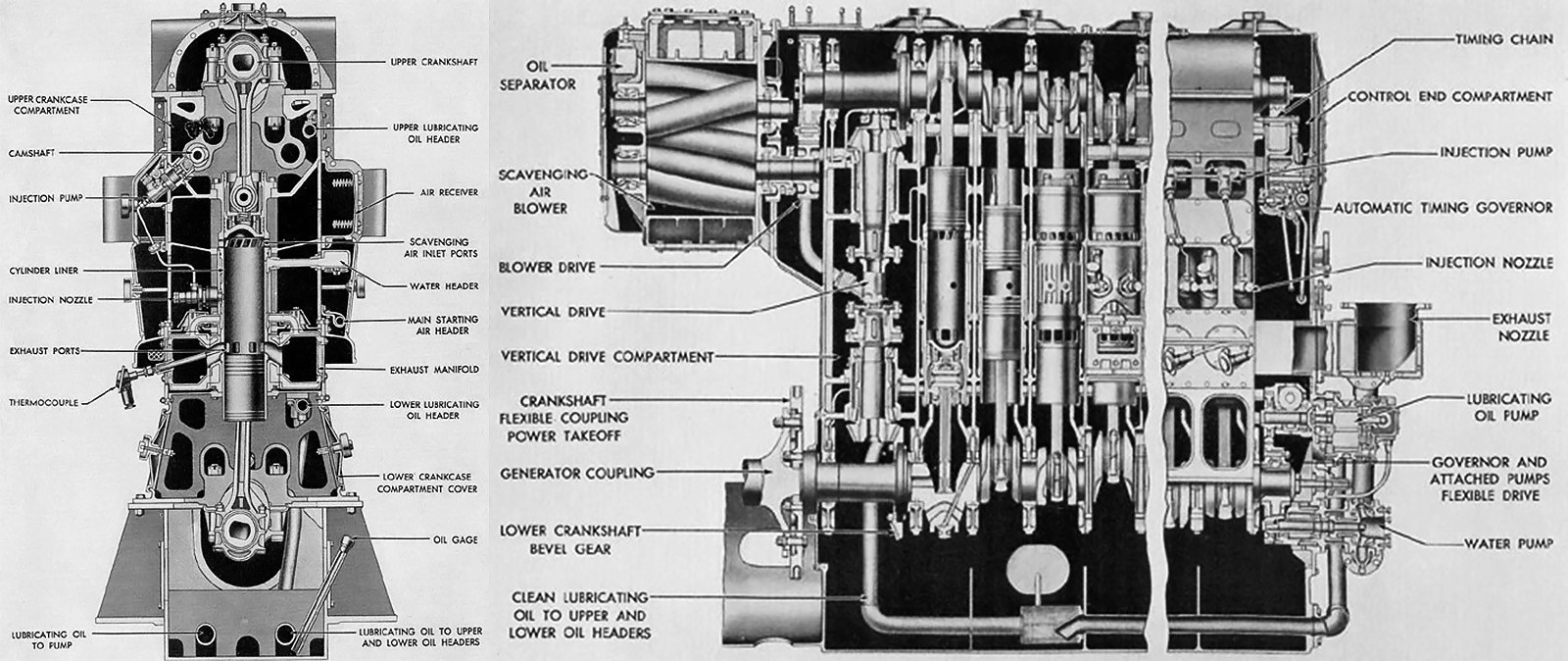
Sectional drawing of the Fairbanks Morse Diamond engine shows the arrangement of its four crankshafts and opposed-piston cylinders. The output shaft is drawn with a six-hole flange and is just below the center of the engine. (Fairbanks Morse image)
Based on the development of the Model 38-series, the Navy approached FM in early 1940 with a request to design and build a 3,000 hp (2,237 kW) opposed-piston engine for submarine use. With the prospect of war looming on the horizon, FM quickly went to work on the new engine design and assigned Robert Beadle as the program’s head engineer. The engine borrowed the basic cylinder design from the 38E5-1/4, but the engine was of a diamond configuration with a crankshaft at each corner. This gave the engine four banks of six opposed-piston cylinders resulting in a total of 24 cylinders.
The FM Diamond engine was of welded steel construction, with the crankcase and four cylinder banks forming a single unit. The lower and upper bank angles were 60 degrees. The left and right bank angles were 120 degrees. A cover concealed each crankshaft, and crankshaft removal allowed access to the cylinder liners. Each forged steel crankshaft was supported by seven main bearings.
The fork-and-blade connecting rods were made from steel forgings and then polished for added strength. The rods were drilled to deliver oil from the crankshaft to the wrist pin and to the underside of the piston crown for cooling. The pistons had a concave crown and formed a somewhat hemispherical combustion space when the two pistons came together. The two-piece pistons were made of cast steel with an aluminum wrist pin carrier.
The cylinder liners were made of forged steel and had a chrome-plated bore. A water jacket was pressed on each liner’s center section, where combustion occurred. Intake and exhaust ports were cast into the cylinder liners, and movement of the pistons covered and uncovered these ports. The upper and lower crankshafts were connected to the “exhaust” pistons that controlled the exhaust ports, and the left and right crankshafts operated the “intake” pistons controlling the intake ports. The crankshafts were phased so that the exhaust pistons (upper and lower crankshafts) led the intake pistons (left and right crankshafts) by about 15 degrees. This allowed for good cylinder scavenging, with the exhaust ports being uncovered (open) before the intake ports and with the intake ports remaining uncovered (open) for a short time after the exhaust ports had been covered (closed).
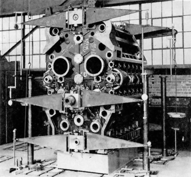
The welded crankcase of the Diamond engine undergoing stress tests before final assembly. The crankshafts and pistons are installed, and the output shaft is visible just below the engine’s center. Note the mounting pads at the top of the engine for the two centrifugal blowers. The blowers fed air into the center of the engine via the two large holes. (Fairbanks Morse image)
The upper crankshaft drove two gear-driven centrifugal blowers (weak superchargers) mounted to the drive end of the engine. The blowers forced air into a central chest inside of the engine diamond. Four compartments, one for each bank, surrounded the intake end of the cylinders and supplied air from the chest. The intake ports in the cylinder liner were tangentially cast so that the incoming air initiated a swirling motion as it entered the cylinder. This swirl helped scavenge the cylinder of exhaust gases and mix the fuel once it was injected. The exhaust end of each cylinder was surrounded by an open passageway that led outside of the engine. A water-cooled exhaust manifold made of welded steel was attached to the side of the engine and collected the exhaust gases.
Each of the left and right crankshafts drove an upper and lower camshaft. The camshafts actuated individual fuel injector pumps for the single fuel injector in each cylinder. The fuel injector was located in the center of the cylinder liner. Fuel was injected into the cylinder at approximately 3,000 psi (207 bar). All of the crankshafts were geared to a single output power shaft, located 13.75 in (349 mm) below the engine’s absolute center. The left, right, and lower crankshafts were each connected to the output shaft via one idler gear. The upper crankshaft was geared to the output shaft through three idler gears. The gears used herringbone teeth. Pressurized air fed through internal piping was used to start the engine.
In designing the engine, FM engineers spent over 6,000 man-hours on torsional vibration calculations alone. The FM Diamond engine was completed in 1942. It had a 5.25 in (133 mm) bore and a 7.25 in (184 mm) stroke (x 2). The engine’s total displacement was 7,533 cu in (123.4 L). The engine was 120 in (3.05 m) tall and 72 in (1.83 m) wide when bare, or 141.5 in (8.73 m) tall and 79.25 in (24.16 m) wide when mounted to its steel stand. Its length was approximately 90 in (27.43 m).
During testing, the Diamond engine produced 3,000 hp (2,237 kW) at 1,500 rpm with 6.88 psi (.47 bar) of scavenging pressure. At this power, the specific fuel consumption was .420 lb/hp/hr (255 g/kW/h). However, the engine experienced constant issues with excessive wear and carbon build-up in the intake and exhaust ports. The program was cancelled at the end of World War II. At the time of cancellation, the experimental Diamond engine had accumulated 2,032 hours of test running.
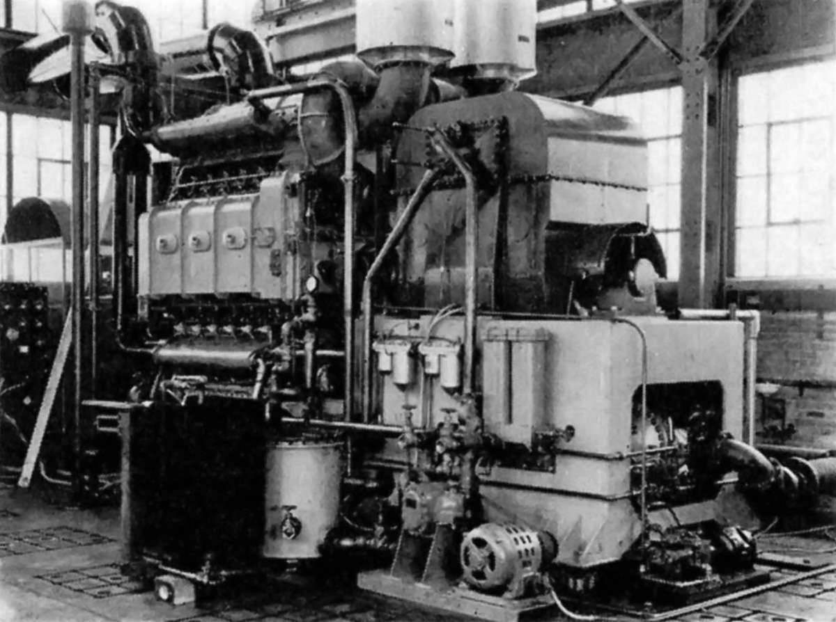
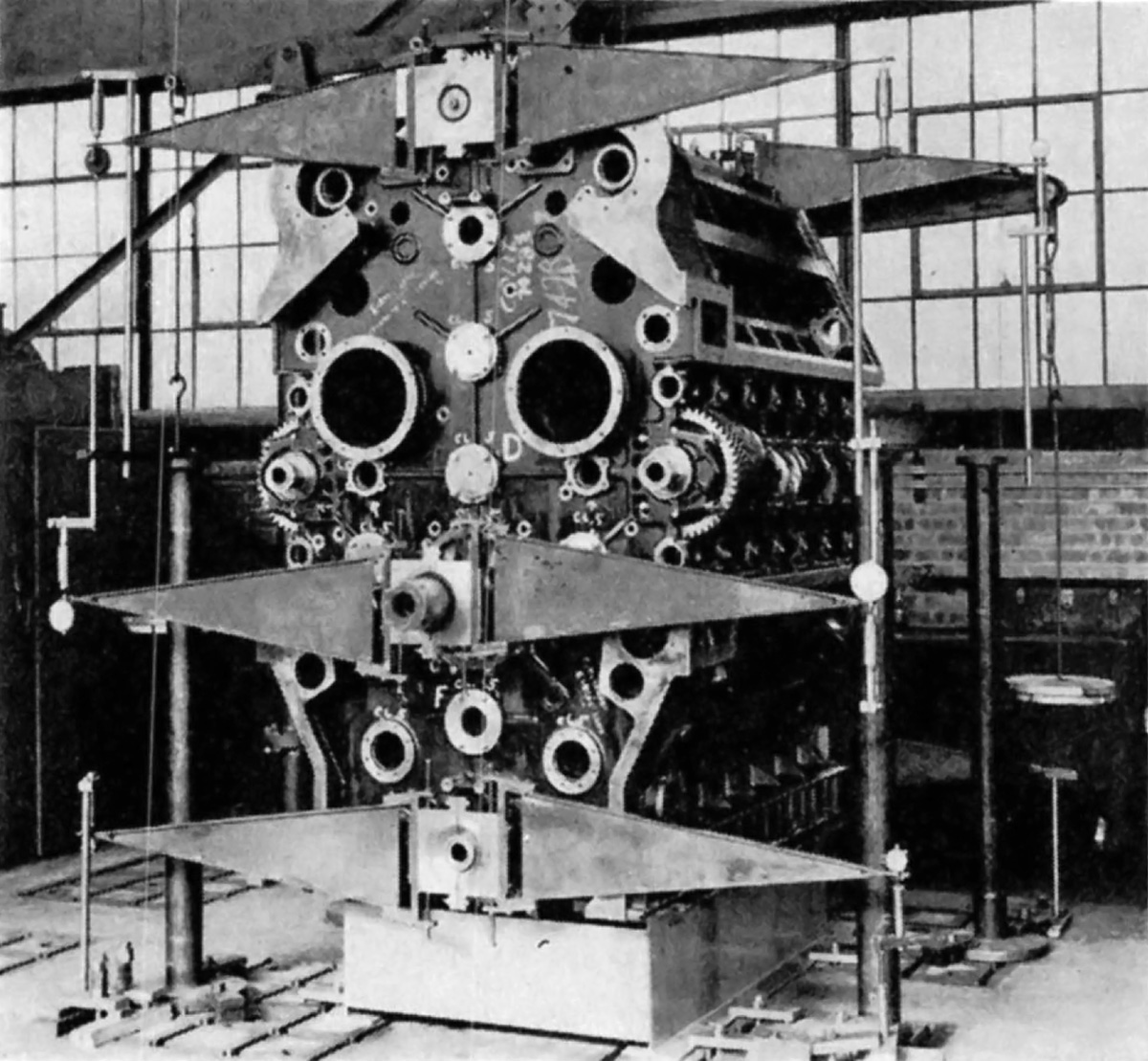
The engine undergoing bench tests. Note the two centrifugal blowers providing air for scavenging and combustion. (Fairbanks Morse image)
Sources:
– “Development of Diamond Opposed-Piston Diesel Engine” by R. H. Beadle (discussion of “The Napier Deltic Diesel Engine”) SAE Transactions Vol 64 (1956)
– Opposed Piston Engines by Jean-Pierre Pirault and Martin Flint (2010)
– Diesels for the First Stealth Weapon: Submarine Power 1902–1945 by Lyle Cummins (2007)
– Submarine Main Propulsion Diesels: NavPers 16161 (June 1946)
– http://www.dieselduck.info/machine/01%20prime%20movers/fairbanks_morse/fairbanks_morse.htm

Bill Pearce is one steely-eyed Indiana Jones of mechanical history. Thanks for that.
Amazing article! Thank you!
Thanks so much for this. The older I get the more I realise how little I know.