

By William Pearce
Giovanni Pegna was an Italian aeronautical engineer who started to design racing seaplanes and other aircraft in the early 1920s. Partnering with Count Giovanni Bonmartini, the pair formed Pegna-Bonmartini in 1922 to bring some of Pegna’s aircraft designs to life. Pegna was particularly interested in designing a racing seaplane for the Schneider Trophy Contest. Pegna-Bonmartini was short lived, as it was bought out by Piaggio & C. SpA (Piaggio) in 1923, when the latter company decided to start designing its own aircraft. Pegna was appointed head aircraft designer for Piaggio.
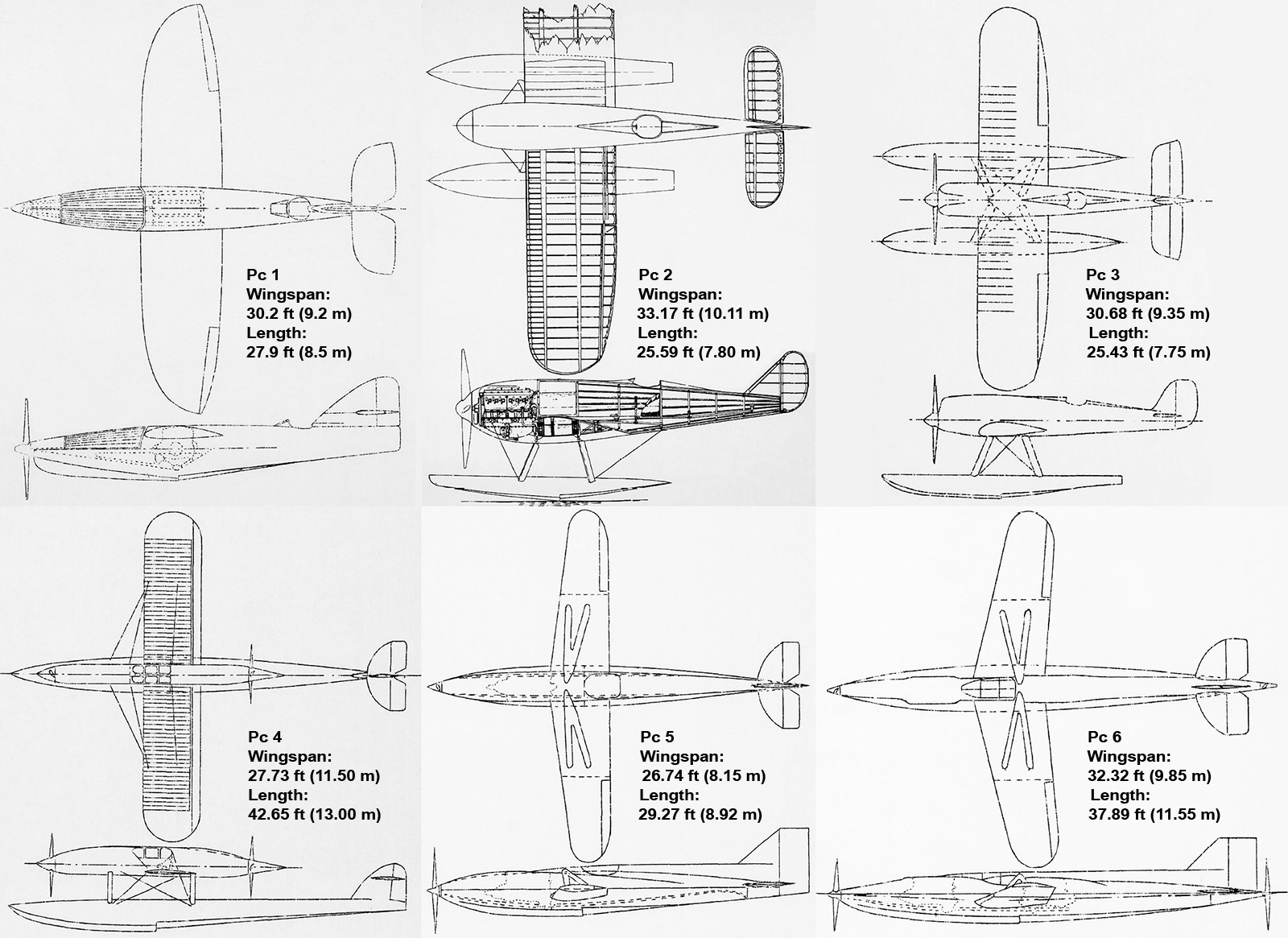
Giovanni Pegna’s previous racing seaplane designs. The engine and propeller of the Pc 1 pivoted up to clear the water for takeoff, landing, and while operating on the water’s surface. The Pc 2 and Pc 3 were fairly conventional designs but were advanced for their 1923 time period. The Pc 4 had tandem engines in a push/pull configuration and a single, central float. Wing floats would have been incorporated into the design. The Pc 5 and Pc 6 both used a retractable hull that was extended for takeoff and landing. The Pc 6 also had tandem engines in a push/pull configuration.
Pegna’s racing seaplane designs focused on minimizing the aircraft’s frontal area. Some of the designs used floats, while others incorporated a flying boat hull. Construction of the Pc 3 was started by Piaggio in 1923. The “Pc” in the aircraft’s designation stood for Pegna Corsa (Race), and this aircraft most likely carried the Piaggio designation P.5. The Pc 3 was a fairly conventional, single-engine monoplane utilizing two floats, but the aircraft was never finished.
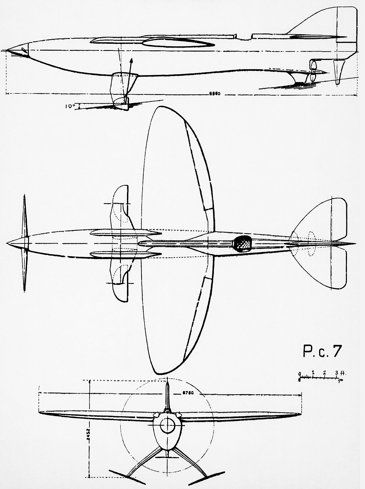
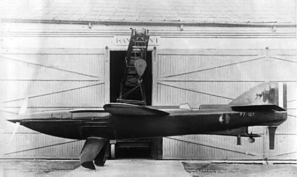
The Schneider Trophy Contest inspired a number of extraordinary designs, but the Piaggio P.7 / Pegna-Piaggio Pc.7 was the most radical to be built. Its hydrovanes were much smaller and lighter than floats, offering the aircraft a distinct advantage if it could get airborne. Note the water rudder behind the water propeller.
In 1927, Pegna was asked by the Ministero dell’Aeronautica (Italian Air Ministry) to design a racing seaplane for the 1929 Schneider Trophy Contest. After studying three designs (Pc 4 through Pc 6), Pegna became increasingly focused on utilizing a central float that would be extended to support the aircraft on water and retracted while the aircraft was in the air. However, the complexity and estimated weight of the float and its retraction mechanism, combined with the unknown aerodynamic forces during retraction and extension, made the design impractical. Pegna returned to the drawing board and, aided by Giuseppe Gabrielli, designed the Pc 7, which was also known as the Piaggio P.7. On 24 March 1928, the Italian Air Ministry ordered two examples of the P.7 and assigned them serial numbers (Matricola Militare) MM126 and MM127.
After experiments in a water tank, Pegna finalized the aircraft’s design. The Piaggio P.7 (Piaggio-Pegna Pc 7) had a watertight fuselage that sat in the water up to the shoulder-mounted wings when the aircraft was at rest. A two-blade propeller at the front of the aircraft was just above the waterline. The engine was located just forward of the wing and drove the propeller via a shaft. A second shaft extended behind the engine to a water propeller positioned in a skeg under the tail. Clutches on both shafts allowed the front propeller or the water propeller to be decoupled from the engine. When the front propeller was decoupled, it would come to rest in a horizontal position. For takeoff, the engine would power the water propeller with the front propeller stationary. As the aircraft gained speed, the front would rise about 10 degrees out of the water by the hydrodynamic forces imparted on two hydrovanes extending below the fuselage and by a third hydrovane located in front of the water propeller. With the front propeller clear of the water, engine power was diverted from the water propeller to the front air propeller. The front propeller would continue the aircraft’s acceleration until enough speed was gained to lift off from the water’s surface.
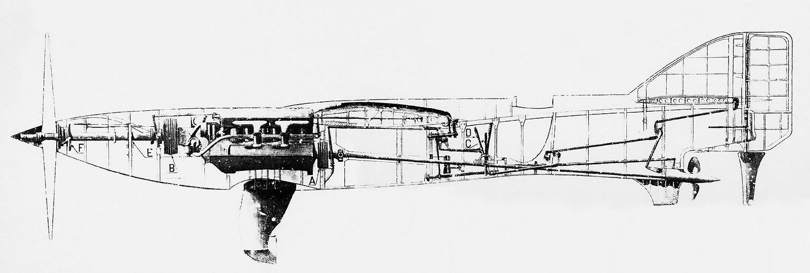
A view of the P.7’s internal layout. A and B are the drive shaft clutches. C is the lever that engages and disengages the air propeller; when disengaged, it locks the propeller in a horizontal position and closes the main carburetor inlets. D is the lever that engages and disengages the water propeller; when disengaged, it feathers the water propeller. E is not recorded, but it appears to be a bulkhead and support for the propeller shaft. F is a rubber diaphragm operated by the air propeller lever that seals the propeller shaft when the air propeller was disengaged.
The P.7’s airframe was made mostly of wood with some metal components. The aircraft was skinned with two layers of plywood with a waterproof fabric sandwiched between the layers. Two watertight compartments were sealed into the fuselage, and the vertical and horizontal stabilizers were watertight. A single fuel tank was positioned in the fuselage under the wing and between the engine and cockpit. The one-piece wing had three main spars and was mounted atop the fuselage. Two legs extended below the fuselage, and each supported a planing surface. The planing surfaces, including the one on the tail, were inclined approximately three degrees compared to the aircraft while in level flight. The relative angle would increase as the aircraft was landed with a slight tail-down configuration. A water rudder extended below the fuselage directly under the aircraft’s tail. The movement of the water rudder and normal rudder were linked.
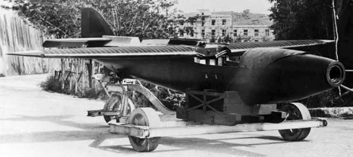
The nearly complete P.7 without its engine or hydrovanes. The original carburetor inlets are visible on the side of the aircraft. Note the pipes for the surface radiators on the wings.
Originally, the P.7 was to be powered by a 1,000 hp (746 kW) FIAT AS.5 V-12 engine. For reasons that have not been found, the engine was switched to an Isotta Fraschini Asso 500 V-12 that produced 800 hp (597 kW) at 2,600 rpm. Isotta Fraschini fully supported the P.7 project, and Giustino Cattaneo, the Asso 500’s designer, redesigned the engine with a rear drive for the water propeller. In addition, new cylinder heads were designed with the exhaust ports on the inner, Vee side of the engine. As originally designed, the Asso 500 had intake and exhaust ports on the outer sides of the engine. Having the open exhaust ports on the side of the fuselage would lead to water intrusion when the aircraft was at rest on the surface. Relocating the exhaust ports to vent out the top of the fuselage resolved this issue. The cylinder heads were most likely the same or very similar to those that Cattaneo had designed for the Savoia-Marchetti S.65 Schneider racer. Cattaneo and Isotta Fraschini also designed at least some of the P.7’s drive systems. Surface radiators on the wings cooled the engine’s water coolant, and engine oil was cooled by a surface radiator on the sides and bottom of the aircraft’s nose.
The cockpit was situated low in the aircraft’s fuselage and between the wing’s trailing edge and the tail. Two levers on the left side of the cockpit controlled the engine’s output to the air and water propellers. One lever engaged and disengaged the air propeller. When engaged, the main carburetor inlets at the front of the aircraft were automatically opened. When disengaged, the carburetor inlets were closed, a rubber seal was pressed against the front of the propeller shaft, and the propeller was slowed and subsequently locked in a horizontal position. The carburetor inlets were originally located on the sides of the aircraft by the engine but were moved to above the nose. When the carburetor inlets were closed, the engine drew in air from the cockpit. When the water propeller’s lever was disengaged, the blades were feathered to offer as little aerodynamic resistance as possible.
The completed P.7 supported by a hoist illustrates the aircraft’s sleek design. The pilot sat quite far aft, and landings would have been a challenge.
Six air propellers were ordered for testing on the P.7. They varied in diameter and profile. Three were made from steel with a ground-adjustable pitch, and the other three were made from duralumin, and each had a different fixed pitch. One of the steel air propellers was designed by Pegna. Originally, the adjustable-pitch water propeller was made from duralumin components, but testing resulted in a switch to a steel hub with duralumin blades. The Piaggio P.7 had a 22 ft 2 in (6.76 m) wingspan, was 29 ft 1 in (8.86 m) long, and was 8 ft (2.45 m) tall. It had a maximum speed of 373 mph (600 km/h) and a landing speed of 103 mph (165 km/h). The aircraft weighed 3,122 lb (1,416 kg) empty and 3,717 lb (1,686 kg) fully loaded.
The design of the complex and unique aircraft delayed its completion. It appears that the first aircraft, MM126, was completed and sent to Desenzano before the Schneider Trophy Contest was held in September 1929, but there was not enough time to test the P.7 before the race. Both P.7 aircraft were finished by late October 1929, which is when testing began. Most pilots of the Italian Reparto Alta Velocità (High Speed Unit) were not interested in testing the radical machine. However, Tommaso Dal Molin was up to the task. Testing occurred on Lake Garda, just off from Desenzano, home of the Reparto Alta Velocità.
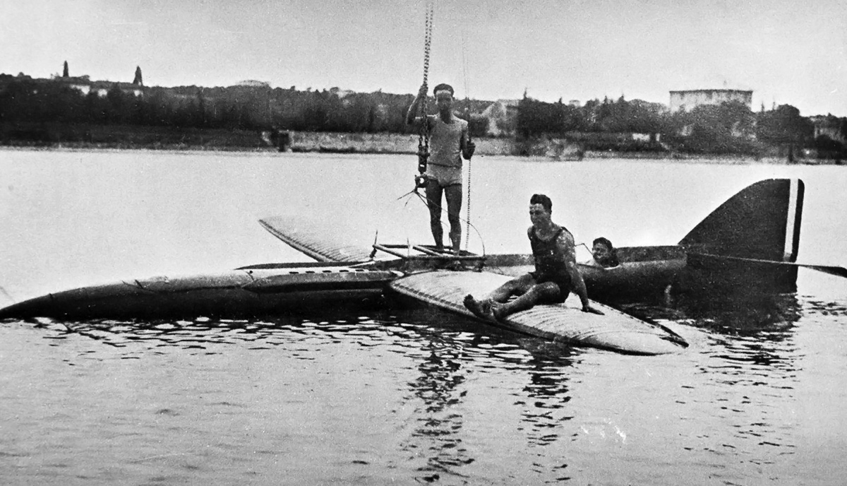
The P.7 on Lake Garda for tests. A simple structure connected to hardpoints above the wing was used to raise and lower the aircraft out of the water. More so that most Schneider Trophy racers, the P.7 could only be operated on calm waters.
Using the water propeller, Dal Molin in MM126 was able to raise the nose of the aircraft to a sufficient height to engage the air propeller, but this was not done. The P.7 was unstable planing on the water, and issues were experienced with the clutch for the water propeller. Oil on the clutch caused it to slip, resulting in a loss of power to the water propeller. In addition, the sudden cavitation of the main hydrovanes while planing caused a loss of buoyancy, which resulted in the P.7 suddenly and violently settling back on the water’s surface. Because of the issues, it seems that tests were conducted over only a few days.
There was no cover to easily access the clutch. The needed repairs would require substantial disassembly of the aircraft. By this time, the Air Ministry and Piaggio showed little interested in the P.7, but Pegna wanted to continue its development. Some of the changes Pegna had in mind were adjustable hydrovanes and cooling the engine oil with water rather than using a surface radiator. However, it appears that the repairs were never made. MM126 was stored at Desenzano for a time but was destroyed after a few years. MM127 was taken to Guidonia Montecelio, near Rome, for testing in a water tank to improve the aircraft’s hydrovanes. The aircraft was eventually abandoned, and it is not clear if any tests were ever conducted. MM127, along with other aircraft, was destroyed in 1944—a casualty of World War II.

The P.7 surrounded by contemporaries at Desenzano. At left is the Macchi M.39. At right is the Savoia-Marchetti S.65. The Macchi M.52’s wing is in the foreground. Note the P.7’s exhaust stacks protruding above the engine.
Sources:
– Some Ideas on Racing Seaplanes (Technical Memorandums National Advisory Committee for Aeronautics No. 691) by Giovanni Pegna (November 1932) 31.4 MB
– Schneider Trophy Seaplanes and Flying Boats by Ralph Pegram (2012)
– MC 72 & Coppa Schneider Vol. 2 by Igino Coggi (1984)
– Schneider Trophy Aircraft 1913–1931 by Derek N. James (1981)
– Volare Avanti by Paolo Gavazzi (2000)
– Jane’s All the World’s Aircraft 1932 by C. G. Grey (1932)

I’ve not received any new essays recently. I trust everything is OK.
Hello Jacques – Thanks for reaching out. All is well, just very busy with the real job and have an overload of other projects, some of which were not planned. Things seems to be settling down, at least I hope.