
By William Pearce
The history of the SNCM 130 and 137 aircraft engines detailed here has been derived from the research of Sébastien Faurès, which he consolidated into his amazing book, Lorraine-Dietrich.
In mid-1935 the French Service technique de l’aéronautique (STAé / Technical Service of Aeronautics) sought the design of a relatively compact aircraft engine that would produce 600 hp (447 kW) at 13,123 ft (4,000 m), displace around 732 cu in (12 L), and weigh 661 lb (300 kg). The air-cooled engine was intended to power the next generation of light fighter aircraft. Albert Lory was put in charge of the new engine design. Lory had previously worked for Delage automobiles and designed the company’s 15S8 Grand Prix racer that won the Manufacturers’ Championship in 1927. Lory also designed the Delage 12 GVis and 12 CDirs inverted V-12 aircraft engines. Working with the STAé, Lory quickly focused on a 24-cylinder engine of either an X, H, or coupled V-12 configuration.

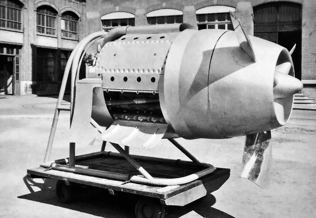
The SNCM 130 / 137 displayed at the Argenteuil factory in mid-1939. This engine was either a mockup or incomplete, but it was outfitted with the envisioned cowling to make it a complete power package. The radiator would be housed between the ducted spinner and engine. Note the induction scoop positioned above the engine and how the valve train covers form part of the cowling. The holes in the cowling were individual exhaust ports. (image Sébastien Faurès/Lorraine-Dietrich)
Throughout 1936, the STAé engine concept changed quite radically, as did Lory’s design. By late 1937, the liquid-cooled engine was made up of four V-6 engine sections joined by a common crankcase and driving a common crankshaft. Each section would produce 600 hp (447 kW), creating a complete engine capable of 2,400 hp (1,790 kW). Few established engine manufacturers were interested in taking on such an unconventional engine, especially one designed outside of their company. On 31 March 1937, France had nationalized the Société des moteurs et automobiles Lorraine (Lorraine Motor and Automobile Company) and created the state-run Société nationale de construction de moteurs (SNCM / National Society of Engine Construction) in its place, with Claude Bonnier as SNCM’s Managing Director and General Manager. In October 1937, the STAé tasked SNCM to develop the new engine.
The 2,400 hp (1,790 kW) engine design was seen as a little too ambitious, and another redesign occurred. The proposed liquid-cooled, 24-cylinder engine was now formed from three V-8 engine sections on a common crankcase. With six banks of four inline cylinders spaced radially around the crankcase, this engine configuration is often called an inline radial. In addition, the outer points of the six banks formed a hexagon, which qualifies the powerplant as part of the family of rare hexagonal engines. Other hexagonal engines include the Curtiss H-1640 Chieftain, the Wright H-2120, the Junkers Jumo 222, and the Dobrynin series of aircraft engines.
The SNCM engine had an ultimate goal of 1,800 hp (1,342 kW), but it would initially be configured to produce 1,600 hp (1,193 kW). Once this power was obtained, the cylinder’s bore would be increased to achieve an output of 1,800 hp (1,342 kW). The 1,800 hp (1,342 kW) engine was designated SNCM 130. The 1,600 hp (1,193 kW) prototype version, with a reduced bore, was designated SNCM 137 and would be built first. Due to the similarity between the engines and their rather confusing genesis, the SNCM 137 engine is often referred to as the SNCM 130.
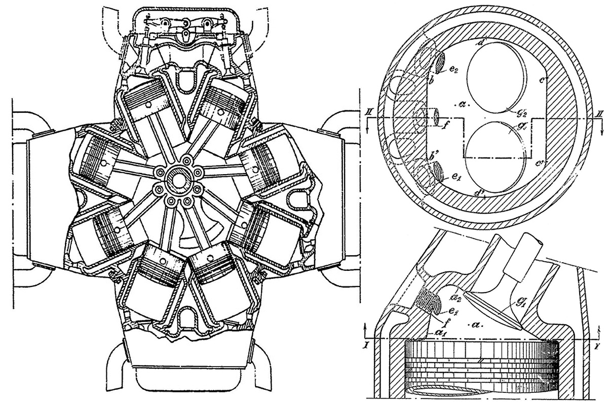
Left, French patent 870,367 drawing showing the four Vee engine sections and the valve train for each cylinder bank pair. Note that the induction was illustrated under the camshaft, which was not the case on the engine as built. Right, French patent 870,359 drawings showing two views of the engine’s combustion chamber. Ports e1 and e2 opposite of the inclined valves were for the spark plugs. Port f was for the fuel injector.
The SNCM 137 had a cast aluminum crankcase made of two-pieces and split horizontally (more like diagonally). The two crankcase halves joined around the four-throw crankshaft, which was supported via five main bearings. A connecting rod consisting of one master rod and five articulating rods was mounted to each of the crankshaft’s throws. Six cylinder banks were mounted at 60-degree intervals around the crankcase. Each cylinder bank consisted of a four-cylinder cast aluminum block with forged steel liners and a detachable cast aluminum cylinder head. The cylinder banks were paired together, forming three groups of eight cylinders. Mounted between each cylinder bank pair was an overhead camshaft that was driven by the crankshaft via a series of gears at the back of the engine. In this configuration, one camshaft served two cylinder banks, and the engine had three camshafts. Each of the two upper camshafts drove a fuel distribution pump from their rear. The single lower camshaft drove an oil pump from its rear and a water coolant pump from its front.
Via rockers, the camshaft actuated the single intake valve and single exhaust valve for each cylinder. The valve train between each cylinder pair was concealed by a large, arched valve cover. The valve cover between the lower cylinder banks extended deeper, past the cylinder heads to act as an oil sump. The valves were inclined in the cylinder head, which had a wedge-shaped combustion chamber. On the side of each cylinder opposite from the valves were two spark plugs and a single fuel injector. The spark plugs were fired by two magnetos driven from the rear of the engine. The engine’s compression ratio was 7 to 1.
A centrifugal single-stage, single-speed supercharger made by Szydlowski-Planiol was located at the rear of the engine, and it provided 3.7 psi (.25 bar) of boost. Air entered the rear of the supercharger, was compressed, and was distributed to each cylinder bank via six separate runners. Each runner was connected to an intake manifold that was cast integral with the cylinder bank. The intake manifolds ran along the outer side of the cylinder bank pairs, although a patent drawing shows the intake located under the camshaft between the cylinder pairs. Exhaust was expelled from a port above each cylinder. An engine mount extended between the intake manifolds in the open Vee between the cylinder banks.
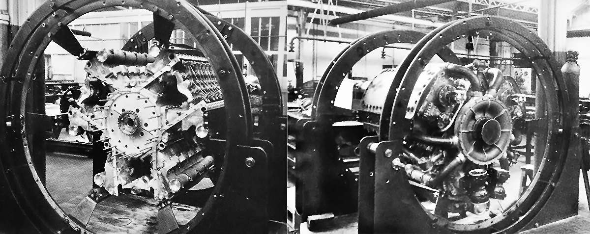
Two images of the SNCM 130 / 137 under construction at the former Lorraine factory. On the left, the valve train is apparent between each cylinder bank pair. Note the diagonal split on the end of the crankcase, which illustrates the crankcase’s two halves. On the right is the rear of the completed engine with its supercharger and intake runners. Note the arched valve train covers. (image Sébastien Faurès/Lorraine-Dietrich)
Mounted to the front of the engine was a propeller gear reduction. Different reductions were available between .333 and .667 crankshaft speed. The gear reduction housing was elongated, and an annular radiator was intended to encircle the housing. A shroud enclosed the radiator, and the propeller’s spinner incorporated a duct to deliver air to the radiator. Three blades in the duct acted as a cooling fan to aid the flow of air through the radiator while the aircraft was on the ground. After flowing through the radiator, the air exited via cowl flaps positioned just before the cylinder banks. As designed, the engine and radiator came fully cowled and represented a power package ready for installation. The gear train covers doubled as part of the engine cowling, with removable panels covering the rest of the engine.
The SNCM 137 had a 5.31 in (135 mm) bore and a 5.12 in (130 mm) stroke. The engine’s total displacement was 2,725 cu in (44.66 L). The SNCM 137 was 46 in (1.18 m) in diameter and was 75 in (1.90 m) long. While Lory continued to lead the project and oversee the engine’s construction, former Lorraine engineer Charles Salusse was also involved with the SNCM 137’s design. Salusse was awarded French patents 870,359 for the combustion chamber design and 870,367 for the Vee-type configurations. Both patents were submitted in November 1940, after Lory had left SNCM following the German occupation, and awarded on 12 December 1941. The second patent illustrates the valve train for the paired cylinder banks and shows the intake positioned under the camshaft. One of the example engines has four Vee-section pairs (eight banks), as considered in an earlier STAé design.
The SNCM 137 was constructed at the former Lorraine plant in Argenteuil, near Paris, France. A mockup, or a partially completed engine, was displayed at the Argenteuil plant in mid-1939. The prototype SNCM 137 was completed by early 1940, and tests were quickly started. By the end of March 1940, 2,000 hours had been completed on a valve test rig, 500 hours of single-cylinder testing had been completed, and the SNCM 137 prototype engine had run for 80 hours. The SNCM 137 had achieved 1,638 hp (1,221 kW) at 3,000 rpm at a simulated altitude of 9,843 ft (3,000 m). However, all further development was stopped with the German invasion on 10 May 1940. Most likely, only the single SNCM 137 prototype engine was built. The SNCM 137 engine was captured by German forces and taken to Germany. The final disposition of the engine has not been found, and no parts of the engine are known to exist.
The SNCM 130 would have been the main production version of the engine, but it was not built. The engine had the same architecture as the SNCM 137, but its bore was enlarged .20 in (5 mm) to 5.51 in (140 mm). This gave the SNCM 130 a total displacement of 2,931 cu in (48.03 L), and its anticipated output was 1,800 hp (1,342 kW) at 3,200 rpm. It was expected to maintain this power to 18,045 ft (5,500 m). Most likely, the small increase in displacement would not alter the engine’s diameter or length from that of the SNCM 137. The SNCM 130 had a forecasted weight of 2,094 lb (950 kg). Some sources refer to the SNCM 130 as the 24E Taurus, with ‘24’ representing the number of cylinders, and ‘E’ standing for étoile, meaning ‘star,’ which is often a foreign term used to describe a radial engine.
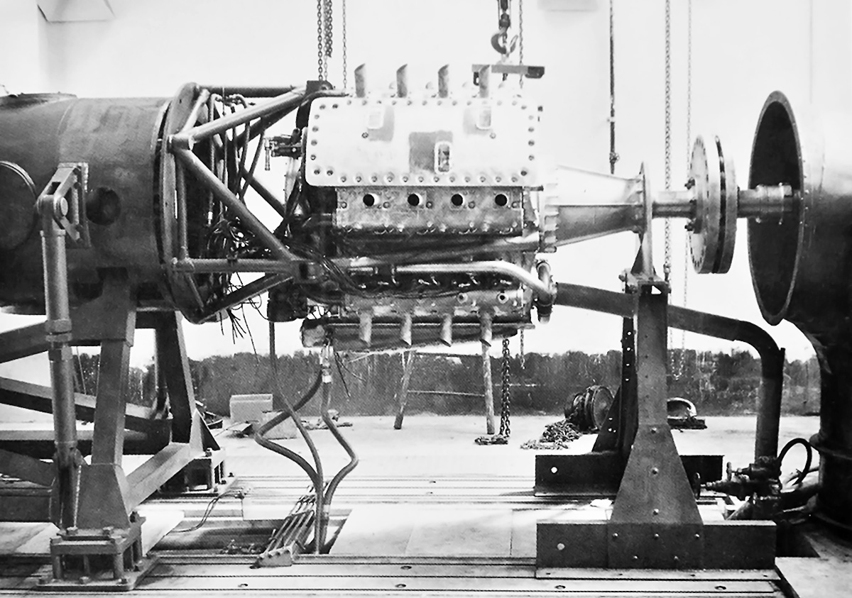
The SNCM 130 / 137 undergoing tests in early 1940. Note the exhaust stacks protruding directly above each cylinder bank and the robust, three-point engine mount. The water pump is visible, attached to the front of the lower camshaft. (image Sébastien Faurès/Lorraine-Dietrich)
Sources:
– Lorraine-Dietrich by Sébastien Faurès Fustel de Coulanges (2017)
– “La S.N.C.M. construit un moteur de 1600 cv,” Les Ailes (6 July 1939)
– Les Moteurs a Pistons Aeronautiques Francais Tome I by Alfred Bodemer and Robert Laugier (1987)

Another great story. Thanks Bill. I enjoy your documentation. It seems to be an engine ahead of its time which I don’t normally associate with the French.
Thanks Dave!
What do you normally associate which “the French”?I’m eager to learn.
Direct fuel injection! Are there other examples of DFI in prewar France? Very interesting. Really striking is the change from the beginning request for proposals to the final prototype. It doesn’t seem to be particularly compact and the choice on valve train seems erroneous, similar to the Chrysler V16, but marginally worse. Considering the 130mm stroke and the 7:1 compression ratio there was plenty of space (18.5mm) to put the spark plugs and fuel injector around the circumference of the cylinder. Great write up. Thank you.
Hello Jiro – There may be, But I can’t say off the top of my head. Some odd stuff with this engine. Glad you liked the article.
Those are some very large crankcase castings!
Hello Tom – There are all sorts of odd stuff with this engine, but sadly, not many photos or drawings of it to get a better idea of how it all came together.