By William Pearce
William “Bill” Powell Lear was born on 26 June 1902 in Hannibal, Missouri. From a very young age, Lear had an interest in electronics and an aptitude for design. Starting in the 1920s and continuing through his entire life, Lear developed a number of electronics, devices, and aircraft. Lear was responsible for the development of the car radio in the late 1920s; various radio direction finders, autopilots, and automated landing systems for aircraft in the 1930s and 1940s; the Lear Jet in the early 1960s; and the 8-track in the mid-1960s. He was personally awarded 121 patents and co-authored another seven. Throughout his life, Lear sold off his successful developments to fund his next round of invention and experimentation.
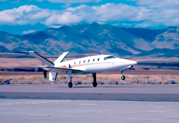
Lear Fan prototype E-001 lands at Stead Airport in Reno, Nevada after a test flight. Despite the nose-up attitude, note the ample clearance between the ventral fin and the runway. The Lear Fan certainly had the appearance of a capable, high-performance aircraft.
In the mid-1970s, and through his LearAvia Corporation located at Stead Airport in Reno, Nevada, Lear worked on a long-range business jet called the LearStar 600. Plans to develop and produce the aircraft were purchased by Canadair in April 1976. Lear and his team worked with Canadair to refine the aircraft, but engineers at Canadair did the same and changed many aspects of the original LearStar 600 design. Around March 1977, the team at LearAvia proposed an updated business jet design called the Allegro, which incorporated many composite components to increase the aircraft’s performance. Canadair was not interested in the Allegro, nor was it interested in Lear’s advice and meddling in the LearStar 600 design, which Canadair eventually developed as the Challenger 600.
Since the 1950s, Lear had contemplated the design of an aircraft utilizing two turboprop engines in the fuselage that powered a single pusher propeller. The benefit of this centerline thrust configuration was that it would provide twin-engine reliability without any yaw effect from asymmetrical thrust in an engine-out situation. The basic design layout was similar to the Douglas XB-42 bomber prototype, which first flew on 6 May 1944, and the Planet Satellite light aircraft, which first flew in mid-1949. In early 1976, Lear discussed the pusher design with Richard Tracy, LearAvia’s chief engineer. Lear sought an aircraft that could carry six to eight passengers from Los Angeles to New York (2,465 miles / 3,967 km) at 400 mph (644 km/h) and at 41,000 ft (12,497 km) with two 500 hp (373 kW) engines. Lear and Tracy intermittently discussed the design for several months.
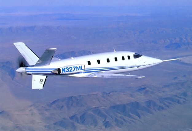
The second Lear Fan prototype E-003 was the primary aircraft for gathering fight test data. E-003 is seen here with its original N-number and blue paint. The number on the ventral fin signified the flight number. Note the data boom on the nose.
As the lack of progress with the LearStar 600 at Canadair grew frustrating for the LearAvia staff, Tracy reviewed the pusher design with Rodney Schapel, an aerodynamic engineer, and tasked him with making some preliminary drawings. Lear was initially not interested in the project and would chastise Schapel when he saw him working on the pusher design. However, as Canadair took control of the LearStar 600 and rejected the Allegro, Lear became more interested in the pusher aircraft and reviewed the design with Schapel and Tracy. Around April 1977, Lear decided that the pusher aircraft would be the company’s next design. The new aircraft was briefly called the Futura, but it quickly became the Lear Fan 2100.
The Lear Fan 2100 was a twin-engine, low-wing monoplane with tricycle landing gear. Depending on the configuration, the aircraft could accommodate one or two pilots and up to nine passengers in its pressurized cabin. Other configurations were considered, including a cargo version and an air ambulance that could accommodate two stretchers, each with a dedicated attendant. The Lear Fan was a revolutionary design in several regards. In addition to its two engines powering a single pusher propeller, Lear had decided that the entire aircraft would be made of a composite material. When compared to aluminum, the aircraft’s bonded graphite and epoxy composite structure was smoother, stronger, resistant to fatigue, would not corrode, could be molded into complex shapes, and was 40 percent lighter. The airframe was designed for a maximum loading of +6 and -4 Gs.
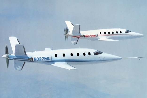
E-001 (right) and E-003 (left) in flight together. Note the fixed cooling air duct on E-003 between the propeller and ventral fin. E-001 had a different setup with a movable door. The “windows” for both aircraft were at least painted on in the photograph.
The aircraft’s fuselage was formed with close-spaced frames and longerons bonded to the outer skin. The skin was mostly four plies thick, but the thickness increased to eight or ten plies around window and door openings. The fuselage was made in six sections: upper and lower nose, upper and lower cabin, and upper and lower rear fuselage. The sections were bonded in an autoclave to form the entire fuselage structure. The fuselage had a slightly oval shape, and its interior had a maximum height of 4 ft 8 in (1.36 m) and a maximum width of 4 ft 10 in (1.47 m). The cabin was 12 ft 10 in (3.91 m) long and had a 50 cu ft (1.42 m3) baggage compartment that was accessible in flight at its rear.
Cabin access was via a door located on the left side of the fuselage and just forward of the wing. The first prototype had a split upper and lower door, but subsequent examples had a single door that folded down to form stairs for cabin entry. The passenger compartment originally had six windows on its right side and five windows on its left side. However, none of the prototype aircraft had their full allotment of windows, and some of the “windows” were painted on. It seems the window on the door was eventually omitted. Pressurization provided a nominal pressure differential of 8.3 psi (.57 bar), enabling an 8,000 ft (2,438 m) cabin altitude while cruising at a 41,000 ft (12,497 km) flight altitude. The steerable nosewheel retracted forward into the nose of the aircraft.
The single-piece, high-aspect wing had three continuous spars and was mated to the fuselage via six attachment points. Each wing spar was formed by two channel sections joined back-to-back on a honeycomb core. The upper and lower wing skins had 52 plies at their roots, with the thickness decreased to eight plies at the tips. The wing had four degrees of dihedral. The main landing gear had an 11 ft 8 in (3.56 m) track and retracted inward to be fully enclosed within the wing. Fuel tanks were integrated into the wing’s structure, and each wing housed up to 125 US gallons (104 Imp gal / 473 L) of fuel. Flaps extended along approximately 75 percent of the wing’s trailing edge, with ailerons extending almost to the wing tips. The landing gear and the flaps were hydraulically operated.
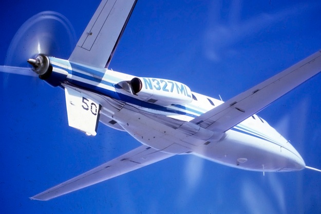
The underside of the Lear Fan as perhaps its least photogenic side. Even so, the view of E-003 illustrates the aircraft’s clean aerodynamic form, even with what appears to be a hydraulic leak from the right main gear. This was the aircraft’s 50th flight.
At the rear of the Lear Fan was a Y tail. The ventral fin had two spars, and a rudder was attached to its trailing edge. The structure of the fin was stressed for ground impacts to prevent the propeller from contacting the runway in case of an over-rotation during takeoff or a hard landing and incorporated a strike pad. Each of the two “butterfly” horizontal stabilizers had one spar. They had 35 degrees of dihedral, which increased the aircraft’s directional stability. The control surface on the horizontal stabilizer was a standard elevator for pitch control only. All normal flight controls were mechanically operated using cables and pushrods.
Originally, two Lycoming (probably LTS101) turboprop engines were to be used, but these were replaced with Pratt & Whitney Canada PT6B-35F engines early in the design phase. The PT6B-35F engines produced 850 shp (634 kW) but were flat-rated to 650 shp (485 kW) for the Lear Fan. The engines were positioned in the fuselage behind the wing’s trailing edge. A scoop on each side of the aircraft brought in air to the engine and expelled exhaust to the rear. The scoop was integral with a large service panel, the removal of which enabled access to the engine. A special mount held each engine in such a way that when the engine was disconnected from its drive shaft and other restrictions, the engine could be swung out for servicing and inspection. The pivot point was the mount at the front of the engine, and this action enabled access to the inner side of the engine.
A 6 ft (1.83 m) aluminum drive shaft with a graphite fiber cover extended from each engine to a combining gearbox at the rear of the aircraft. The gearbox was designed and built by Western Gear Corporation and was equipped with sprag overrunning clutches. If an engine failed, the good engine would continue to power the propeller. As originally designed, wax contained in the gearbox would melt to provide continuing lubrication in the event of oil loss. This method did not work as well as expected, and a back-up oil system was devised in 1984. Referred to as the “spin jet,” oil from a reserve tank was intermittently sprayed directly into the meshing gears. The gearbox was successfully run for over three hours with its main oil supply exhausted and its only lubrication provided by the “spin jet” system. An oil cooler was located under the gearbox. The gearbox had a .3125 propeller speed reduction, resulting in the propeller turning at 688 rpm when the engine’s drive shaft was rotating at 2,200 rpm. Originally, a 7 ft 6 in (2.29 m) diameter three-blade propeller built by Hartzell was to be used. However, a switch to a four-blade Hartzell propeller of the same diameter was made during the design phase when tests indicated that the four-blade propeller was less prone to vibration issues. The propeller was reversible and had 3 ft 1 in (.94 m) of ground clearance when the aircraft was on its landing gear.
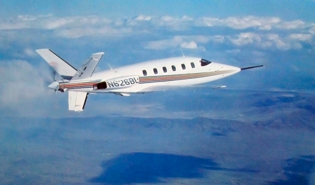
E-001 with its updated paint, which it still wears today. The two ducts under the aircraft were the inlet and exhaust for oil coolers. An open cooling air exit door is seen between the propeller and ventral fin. Subsequent prototypes used a fixed duct. Most images of E-001 in flight are without a spinner.
Although a Lear Fan brochure dating from 1979 lists the aircraft’s length as 38 ft 8 in (11.79 m), as originally built, the aircraft had wingspan of 39 ft 4 in (11.99 m), a length of 39 ft 7 in (12.07 m), and a height of 11 ft 6 in (3.51 m). The Lear Fan’s estimated performance was a top speed of 375 mph (604 km/h) at 39,000 ft (11,887 m), 403 mph (649 km/h) at 31,000 ft (9,449 m), and 414 mph (666 km/h) at 19,000 ft (5,791 m). Stalling speed was 90 mph (145 km/h). The aircraft had an initial climb rate of 3,550 fpm (18.0 m/s), and a ceiling of 41,000 ft (12,497 km). The Lear Fan had an empty weight of 3,650 lb (1,656 kg) and a gross weight of 7,200 lb (3,266 kg). At gross weight, the aircraft had a range of 1,630 miles (2,623 km) at 400 mph (644 km/h) and 2,300 miles (3,704 km) at 350 mph (563 km/h). On a single engine, the Lear Fan could takeoff, climb at 1,900 fpm (9.7 m/s), and execute a go-around. The aircraft’s single engine ceiling was 29,000 ft (8,839 m).
Lear was slowed down by health problems for a few years, but he was back to his old self in late 1977 as he tried to sell the Lear Fan concept to anyone who would listen. Lear made the decision to proceed with production prototypes rather than constructing a proof-of-concept vehicle first. While this decision could lead to cost savings and quicken development if everything went well, it would result in the exact opposite if things did not go well. By this time, Tracy had been replaced as chief engineer by Nicholas Anderson, and Schapel had been fired. Schapel had designed the aircraft’s original Y tail, but Lear wanted an inverted V tail. Schapel was let go over the disagreement. Ultimately, wind tunnel tests indicated that the Y tail was superior, and the Lear Fan reverted back to Schapel’s original tail design.
In early 1978, Lear’s health faltered again. He made arrangements for Lear Fan development to procced even if he were to die, but he desperately wanted to live long enough to see the prototype take to the air. In March, Bill Lear was diagnosed with leukemia, and he passed away on 14 May 1978. Some of his last words were urging that the Lear Fan be finished.
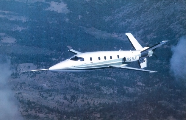
E-003 with its revised green paint and new N-number. The green paint was applied in honor of the Zoysia Corporation, the project’s major financial backer at the time. The number on the ventral fin indicates that this is the aircraft’s 298th flight. A spin chute is installed between the V tail. Although spin testing was never conducted, if needed, a shaped charge would have blown off the propeller before the chute was deployed.
Development of the Lear Fan did continue, and construction of a prototype was started in November 1978. Moya Lear, Bill’s wife, took over as the face of LearAvia. Progress on the aircraft’s untried propulsion system and gearbox, unusual layout, and all-composite structure proved slow and expensive. LearAvia’s financial resources were quickly depleted. In mid-1980, the company was restructured as Lear Fan Limited with the financial backing of investment firms and the British government. The agreement with the British government was that $25 million would go to the project, and another $25 million would be provided for Lear Fan production in Newtonabbey, near Belfast in Northern Ireland. British financial support would end if the prototype did not fly by the end of 1980. At the time, 126 aircraft were on order. Production was expected to start in 1982 and would create at least 1,200 jobs in Newtonabbey. Paramount for Lear Fan production was for the FAA (Federal Aviation Administration) to issue the aircraft a Certificate of Airworthiness. However, the Lear Fan’s all-composite construction was a first for a production aircraft, and certification was going to be a long and costly process.
Under the newly restructured company, the aircraft became the Lear Fan Limited LF 2100, and all prototypes were registered with the FAA as such. Lear Fan E-001 was registered as N626BL, for June 26 (his birthday) Bill Lear. On 31 December 1980, E-001 was rolled out of the hangar at Stead Airport to conduct taxi tests before its first flight. During a high-speed taxi test, the brakes were burned up and needed to be replaced. With 15 minutes of daylight left, the aircraft was preparing for takeoff when the sleeve of a pilot’s flight suit caught on the cockpit fire extinguisher handle, inadvertently activating it and forcing the flight to be scrubbed. The next day, 1 January 1981, the Lear Fan took to the air. The first takeoff was made by Hank Beaird in the left seat, with Dennis Newton in the right seat. The first landing was made by Newton in the left seat, with Beaird in the right seat. It was Beaird’s idea to switch seats so that both pilots had “firsts” during the Lear Fan’s initial flight. While the aircraft’s first flight was one day past the deadline, in the spirit of all that had been accomplished and by a Royal Decree signed by Queen Elizabeth, the British government declared that the Lear Fan made its first flight on 32 December 1980 and was still qualified for funding.
The remainder of 1981 was spent refining E-001 and continuing flight testing, building E-002 for use as a static test airframe, and building E-003. E-003 was registered as N327ML, for March 27 (her birthday) Moya Lear, and the aircraft was planned as the true workhorse for flight testing. With Lear Fan orders reaching 203 by June 1981 and 263 by early 1982, the future looked bright. E-001 had made 53 flights and had accumulated 78 flight hours by the start of 1982.
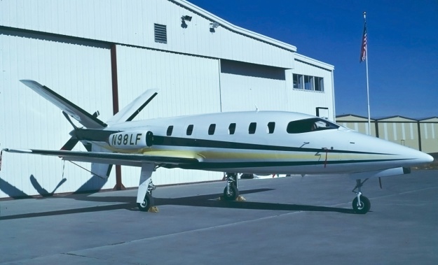
The third Lear Fan prototype, E-009, seen outside the Lear Fan hanger at the Stead Airport. E-009 appears to have had all of its windows from the start. Although not quite apparent from the image, its colors were dark green and yellow on white.
The second prototype, E-003, had a new fuselage that was 12 in (.30 m) longer than that used on E-001, resulting in a length of 40 ft 7 in (12.37 m). The longer fuselage increased the cabin’s length to 13 ft 4 in (4.06 m) and the baggage compartment’s capacity to 53.7 cu ft (1.52 m3). The aircraft also incorporated some other minor modifications, such as a ventral duct at the extreme rear to bring in cooling air to the gearbox. E-003 made its first flight on 19 June 1982, most likely piloted again by Beaird and Newton. However, Lear Fan Limited had run out of money. The company was reorganized on 15 September 1982 as Fan Holdings, Inc, with the British investing $30 million and with the Zoysia Corporation, a consortium from Saudi Arabia, supplying $60 million. A major player in the Zoysia consortium was Prince Sultan bin Salman bin Abdulaziz Al Saud.
In December 1982, cracks in the wing were detected during static tests. Rather than undergoing a major wing redesign, the existing wing structure was reinforced. These modifications added weight and reduced the fuel load by 10 US gallons (8 Imp gal / 38 L), both of which decreased the aircraft’s range. At the start of 1983, 276 Lear Fans were on order. Flight testing of E-001 and E-003 resumed during the summer of 1983. In mid-July, the lower aft pressure bulkhead of the static test airframe E-002 failed during a pressurization test. On 20 July 1983, E-001 suffered an explosive decompression while at 25,000 ft (7,620 m). With the recent failure of E-002 on their minds, test pilots John Penny and Mark Gamache declared an emergency and brought the aircraft quickly and safely back to Stead Airport. The cause of the decompression could not be found, and the event marked the end of E-001’s flight career.
In December 1983, another test fuselage failed during pressure tests, and Fan Holdings Inc was running short on funds. At the time, Lear Fans had accumulated some 521 total flight hours. In March 1984, E-003 flew with its updated wing and fuselage. In April 1984, more fuselage issues were encountered. In June 1984, the Newtonabbey plant, which had been tooled up for production and had made various test parts, was shut down. Also in June 1984, the registration of E-003 was changed from N327ML to N21LF. Bill Lear’s will had focused on continuing Lear Fan development, but it created some potential conflicts of interest with the aircraft’s management team. Some of the Lear children filed suit in 1978 and 1979. Moya Lear became involved, and everything was settled as far as the courts were concerned in 1984. However, not all parties were appeased, and some consider the N-number change was done to spite Moya. Others feel it was to bring focus to the Lear Fan rather than to people behind the project.

E-001 on display in the Museum of Flight in Seattle, Washington. The aircraft is in good company with the likes of a Douglas DC-3, Boeing 80, Gee Bee Z, and Lockheed M-21/D-21 in the background. (Josh Kaiser image via airliners.net)
Airframes E-004 through E-008 were all test articles for certification, but the continuous issues resulted in there being no end in sight for the certification process. In late 1984, Fan Holdings Inc was attempting to get the Lear Fan certified for unpressurised, VFR (Visual Flight Rules), day flight by January 1985. Certification for pressurized flight up to 25,000 ft (7,620 m) would follow in the spring of 1985, and certification up to 41,000 ft (12,467 m) would follow in mid-1985.
On 15 December 1984, airframe E-009 (N98LF) made it first flight with John Penny and Bob Jacobs at the controls. In April 1985, the aircraft was flown to William P. Hobby Airport in Houston, Texas to give Sultan bin Salman an orientation flight. At the time, Sultan bin Salman was undergoing training for his Space Shuttle flight abord Discovery, scheduled for June 1985. Most likely, it was hoped that the Lear Fan orientation flight would also result in additional financing from the Zoysia Saudi Arabian consortium, but it was not to be. On 25 May 1985, development of the Lear Fan was halted; all employees in Reno and Newtonabbey were let go, and all Fan Holdings Inc facilities were closed.
The Lear Fan’s revolutionary design and construction proved too much to overcome. The decision to develop the aircraft without a proof-of-concept proved costly, as numerous changes needed to be made. Problems had also been encountered with the gearbox, and its excessive wear was cited as the final blow to the program. After 200 hours of inspection, the FAA refused to issue a Certificate of Airworthiness for the Lear Fan. Some contend that the FAA set requirements for the Lear Fan that were two to three times more stringent than those for a comparable aluminum aircraft.
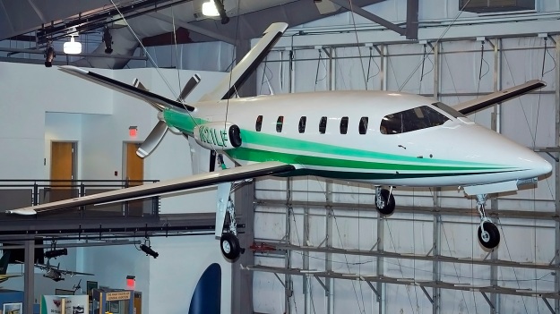
E-003 hangs on display in Frontiers of Flight Museum at Love Field in Dallas, Texas. Black pneumatic de-icing boots covered the Lear Fan’s leading edges. Hot exhaust from the engines would prevent the buildup of ice on the propeller. (Johnny Comstedt image via http://www.aviationmuseum.eu)
The final disclosed specifications for the Lear Fan were a wingspan of 39 ft 4 in (11.99 m), a length of 40 ft 7 in (12.37 m), and a height of 12 ft 2 in (3.71 m). The aircraft had a maximum speed of 414 mph (666 km/h) at 20,000 ft (6,096 m) and a stalling speed of 88 mph (142 km/h). Best economical cruise speed was 322 mph (518 km/h) at 40,000 ft (12,192 m), which gave a maximum range of 2,003 miles (3,224 km). The Lear Fan had an initial climb rate of 4,000 fpm (20.3 m/s) and a ceiling of 41,000 ft (12,497 km). The aircraft had an empty weight of 4,100 lb (1,860 kg) and a gross weight of 7,350 lb (3,334 kg). At gross weight, the Lear fan had a range of 1,782 miles (2,868 km). Single engine performance was a 1,300 fpm (6.6 m/s) climb rate and a 33,000 ft (10,058 m) ceiling.
Compared to the original flight specifications, the aircraft had become 450 lb (204 kg) heavier. While its maximum speed had increased by 14 mph, its maximum range at gross weight decreased by 670 miles (1,078 km), and its economical cruising speed decreased by 28 mph. After a peak of some 280 aircraft on order, most customers requested a refund as development dragged on. The entire Lear Fan project had consumed over $250 million.
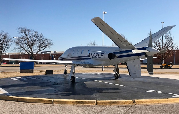
E-009 on display at the FAA’s Civil Aerospace Medical Institute in Oklahoma City, Oklahoma. The aircraft was previously in outside storage at the FAA facility and underwent a restoration starting in 2012. The new paint scheme was applied during the restoration. A dedication ceremony for the restored E-009 was held on 29 September 2015.
Years after their development was abandoned, Lear Fan airframes continued to be used to understand composites and develop techniques for their inspection. From November 1993 to October 1994, Northrup Grumman inspected the composite wing structure of E-009. The project was sponsored by US Department of Transportation and NASA to develop inspection techniques for composite aircraft. Although minor defects were detected, they were evaluated as not severe enough to impose a threat to the integrity of the wing structure. The final inspection report advised that composite assembly standards should be established to minimize defects and damage. It was noted that E-009 had about 230 flight hours.
The FAA acquired two Lear Fan test airframes, presumably from the E-004 to E-008 group. The airframes were tested at the Impact Dynamics Research Facility at the NASA Langley Research Center in Hampton, Virginia. The tests involved swinging the airframes into the ground from a 240 ft (73 m) gantry. This produced a 56 mph (90 km/h) forward velocity and an 1,860 fpm (9.4 m/s) descent rate at impact. The first aircraft was unmodified and tested in 1994. The fuselage broke in two above the wing, and the measured impact forces were greater than those recorded with comparable aluminum aircraft. The deformation and crumpling of aluminum absorbed some of the impact energy, while the composite structure of the Lear Fan absorbed less energy. The second airframe was modified with a composite, energy-absorbing subfloor and was tested on 15 October 1999. In addition, a plywood structure was built for the aircraft to collide with after ground impact. The fuselage cracked in a similar manner to the first airframe but the separation was less.
All three completed Lear Fan aircraft survive. E-001 (N626BL) hangs from the ceiling in the Great Gallery at the Museum of Flight on Boeing Field in Seattle, Washington. E-003 (N327ML/N21LF) hangs from the ceiling in the Frontiers of Flight Museum at Love Field in Dallas, Texas. E-009 (N98LF) was purchased by the FAA and is displayed outdoors at the Civil Aerospace Medical Institute, part of the Mike Monroney Aeronautical Center, adjacent to the Will Roger Airport in Oklahoma City, Oklahoma.
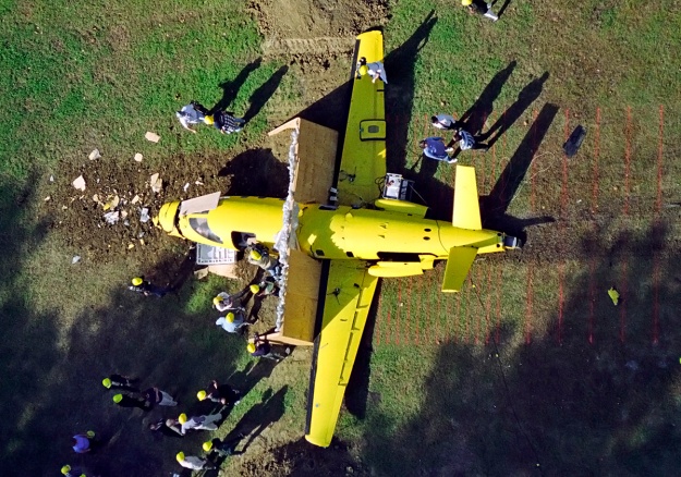
The second of two incomplete Lear Fan airframes owned by the FAA. The aircraft is pictured after its impact test on 15 October 1999. Off frame to the right is the concrete surface where the airframe made initial contact. It then slid onto the grass (note the red marker lines) and through the plywood barrier. A dirt berm was built-up on the left side of the plywood. Cracks in the fuselage can be seen near the plywood. The left engine cover with its integral duct have separated from the airframe. (NASA/Langley Research Center image)
Sources:
– Email correspondence with John Penny
– Stormy Genius by Richard Rashke (1985)
– Lear Fan (brochure) by LearAvia Corp (1979)
– Lear Fan Propulsion System by Daniel E. Cooney (April 1980)
– Jane’s All the World’s Aircraft by John WR Taylor (various editions 1979–1985)
– “Lear Fan 2100—first report” by Bill Sweetman, Flight International (10 January 1981)
– “Lear Fan collapses,” Flight International (8 June 1985)
– “Crosswind Takeoff” Enterprise (video, 1984)
– Structural Integrity Evaluation of the Lear Fan 2100 Aircraft by H. P. Kan and T. A. Dyer (May 1996)
– Simulation of an Impact Test of the All-Composite Lear Fan Aircraft by Alan E. Stockwell (October 2002)
– https://www.aviastar.org/air/usa/learavia_learfan.php

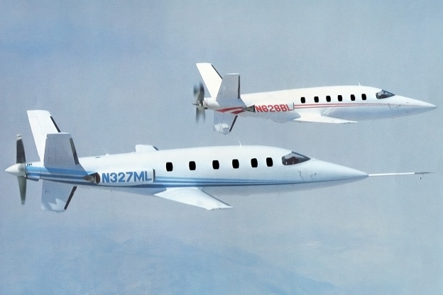
I saw the ‘Fans several times when I started attending the Reno Air Races in 1981. At one time during one of the shows 001 and 003 made a formation fly-by similar to the photo above, but I think 003 had it’s green paint by then. I KNOW it was green when I shot about a shoebox full of photos of the test pilot giving the plane a full walk-around inspection before taking off on another test flight. Sadly I lost those photos during a move.
During the races I stumbled across the air-band frequency they were using during the flight. The pilot was conducting low-speed stall tests, and I could hear that the plane would always break to one side at some point during the stall, probably due to prop torque.
Bummed it never made it to production. The OMAC canard was also being developed up there at Stead during this period, another dead-end project that promised much.