Category Archives: Post World War II

SNCAC-NC-3021-front-no-cowling

SNCAC NC 3021 Belphégor High-Altitude Research Aircraft

By William Pearce

In the early 1930s, Avions Farman (Farman) built the F.1000-series of aircraft to break altitude records. On 5 August 1935, the F.1001 reportedly achieved stable flight at around 10,400 m (34,120 ft). However, one of the small windows in the aircraft’s pressure vessel soon failed. The sudden decompression incapacitated the pilot, Marcel Cognot, and the aircraft crashed.

SNCAC-NC-160-model

Model of the pre-war NC 160 dive bomber displays the basic layout that would be scaled-up for the NC 3020.

In late 1936, France began a program of nationalizing its arms industry, which many aviation manufacturers fell under. In early, 1937 Farman was combined with Aéroplanes Hanriot to create the state-run Société Nationale des Constructions Aéronautiques du Center (SNCAC or Aérocentre, the National Company of Aeronautical Constructions of the Center).

SNCAC initiated development of some advanced aircraft and designed other aircraft to serve as technological testbeds. One of these aircraft was the NC 130 (NC standing for Nationale Center), a twin-engine monoplane built around a cabin pressure vessel. The NC 130 was designed by Marcel Roca, the former head of the Farman design office, and it had an anticipated service ceiling of 34,777 ft (10,600 m). The NC 130 made its first flight in 1939 but was destroyed in the early part of World War II. Roca and his team also designed the NC 160, a monoplane dive bomber with contra-rotating propellers. The NC 160 did not progress beyond the design stage.

After the German invasion of France on 10 May 1940, SNCAC personnel and offices were relocated south from Boulogne-Billancourt, near Paris, and untimely to Cannes on the Mediterranean Sea. SNCAC, along with SNCASE (Société nationale des constructions aéronautiques du Sud-Est, National Company of Aeronautical Constructions of the South East), SNCAO (Société nationale des constructions aéronautiques de l’ouest, National Company of Aeronautical Constructions of the West), and CAMS (Chantiers Aéro-Maritimes de la Seine, Aero-Maritimes construction sites of the Seine) were combined with and operated under SNCASO (Société nationale des constructions aéronautiques du sud-ouest, National Company of Aeronautical Constructions of the South-West). At the time, southern (Vichy) France operated as an independent and unoccupied ally of Germany, but the state’s “independence” from Germany was certainly not absolute. The German overseers allowed the continued development of commercial and civil aircraft in Southern France.

SNCAC-NC-3021-right-side

The NC 3021 before the dorsal fairing was added forward of the vertical stabilizer. Note the glazing on the lower fuselage. Between the panels was the lower pressure cabin bulge with observation ports.

Roca and the SNCAC team were put in charge of the special aircraft division, which would use the SO 3000-series to designate their designs, SO standing for Sud-Ouest (South West). The SO 3020 was an experimental high-altitude research aircraft designed to observe stratospheric and meteorological conditions, and the basic layout of the aircraft was based on a scaled-up version of the pre-war NC 160 dive bomber design.

The fuselage of the large, taildragger aircraft consisted of three sections. The forward fuselage housed two 1,400 hp (1,030 kW) Hispano-Suiza 12Z engines placed side-by-side and mounted on a tubular frame. Each engine powered half of a six-blade, coaxial, contra-rotating propeller via a SNCAC-designed combining gearbox designated NC T1.

The central fuselage was built around a welded pressure vessel that was 17 ft 1 in (5.20 m) long and 5 ft 7 in (1.70 m) in diameter. A bulge atop the pressure vessel was the cockpit that protruded above the fuselage. A bulge in the lower part of the pressure vessel contained two viewing stations for observations and photography of the stratosphere. The lower bulge was contained within the aircraft’s fuselage, but the fuselage was glazed around the bulge. The cabin pressure vessel accommodated five people: the pilot, a radio operator/navigator, a mechanic, and two scientists/observers. Pressurization of the cabin was achieved by two SNCAC-designed NC 41 positive displacement compressors that were driven directly from the engines. The cabin was accessed via a door in the rear fuselage that led to a hatch at the back of the pressure vessel.

SNCAC-NC-3021-right-rear

Rear view of the NC 3021 illustrates the upper pressure cabin bulge for the cockpit. Note the observation ports on the side of the fuselage.

While the forward and center fuselage sections were all-metal monocoque designs, the rear fuselage had a spruce frame that was covered in plywood. The vertical and horizontal stabilizers were also made of wood, but the rudder and elevators had metal frames that were covered with fabric.

The SO 3020’s three-spar wing was of mixed construction, and the main spar attached to a bulkhead that was mounted to the pressure vessel in the central fuselage. The structure of the wing was made mostly of metal, but spruce was used for the front and rear spars of the outer wing sections. The wing was covered with metal. The ailerons had metal frames and were covered in fabric. When retracted, the landing gear was fully enclosed with the main gear in the wing and the tailwheel in the fuselage. The main gear had a wide track of 18 ft 9 in (5.71 m). Tanks within the wings held the aircraft’s 1,836 US gal (6,950 L / 1,529 Imp gal) of fuel.

The SO 3020 had a wingspan of 73 ft 3 in (22.32 m), a length of 65 ft 3 in (17.90 m), and a height of 19 ft 2 in (5.83 m). It was anticipated that the aircraft would cruise at 311 mph (500 km/h) at 33,793 ft (10,300 m) and have a ceiling of 45,932 ft (14,000 m). The SO 3020 had an empty weight of 13,382 lb (6,070 kg) and a gross weight of 26,015 lb (11,800 kg). This would allow the aircraft to carry 11,023 lb (5,000 kg) of fuel, 1,014 lb (460 kg) of freight, and five crew members. Range was 4,169 miles (6,710 km) with an endurance of seven hours.

SNCAC-NC-3021-front-no-cowling

The maintenance crew underneath the uncowled NC 3021 provides reference to just how large the aircraft was. The duct supplying air to the supercharger can be seen along the side of the engine. Note the open access door in the rear fuselage.

Work on the SO 3020 was allowed to move forward in mid-1941, but progress was slow due to the war situation. A full-size wooden mockup was built toward the end of 1942. When Germany invaded Vichy France in early November 1942, progress on the SO 3020 slowed even further. In March 1943, the letter designation ‘B’ was assigned to SNCASO aircraft, and the SO 3020 was given the name “Belphégor,” for the demon who seduces people by suggesting to them ingenious inventions that will make them rich.

Construction of the SO 3020 continued throughout the war. The aircraft, its design team, and other SNCASO operations were moved west to Le Flayosquet in early 1944. This move was a result of a British air raid on Cannes in November 1943 and was finally completed in May 1944. However, after the Allied landings and subsequent liberation of France, everything was moved back to Cannes between November 1944 and January 1945. With the liberation of France, the nationalized aircraft manufacturers were restored, and SNCAC broke off from SNCASO. The SO 3020 and everything else associated with SNCAC was moved back to Boulogne-Billancourt.

By early 1946, the SO 3020 was complete with the exception of its engines. The war had delayed work on the Hispano-Suiza 12Z, and it would be some time before the engines would be available. As a result, the decision was made to switch to a single 2,950 hp (2,170 kW) Daimler-Benz DB 610 engine. The DB 610 consisted of two coupled DB 605 engines and was similar to what was planned with the two 12Z engines and the NC T1 gearbox. DB 605 engines were available to France and SNCAC in the immediate post-war era. With this new configuration, the aircraft was redesignated NC 3021. At the time, a number of experiments were planned for the aircraft to study cosmic rays and their interaction with the atmosphere.

SNCAC-NC-3021-front

Front view of the NC 3021 displays the DB 610’s side and lower exhaust stacks. Note the duct under the engine to supply air for cabin pressurization. The engine and propeller were most likely repurposed from stock intended for a German Heinkel He 177 bomber.

In March 1946, the NC 3021 was transferred from Boulogne-Billancourt to the Toussus-le-Noble airfield for final assembly. With the DB 610 engine, the contra-rotating propellers were discarded, and a single, four-blade propeller was used. This VDM propeller was 14 ft 9 in (4.5 m) in diameter and was most likely the same as that used on the German Heinkel He 177 bomber. The DB 610 engine was mounted on a tubular frame at the front of the aircraft, and an annular radiator was installed around the propeller’s extension shaft. Ducts on each side of the cowling delivered air to the transversely-mounted superchargers at the rear of the engine. Air for the cabin and its pressurization was brought in from a duct under the spinner. This sealed duct passed around the lower exhaust stacks which helped heat the air.

The NC 3021 had a wingspan of 73 ft 3 in (22.32 m), a length of 65 ft 3 in (17.90 m), and a height of 19 ft 2 in (5.83 m). The aircraft’s estimated performance was a maximum speed of 348 mph (560 km/h) at 19,685 ft (6,000 m) and a cruising speed of 280 mph (450 km/h) at 39,370 ft (12,000 m). The aircraft had a landing speed of 87 mph (140 km/h), an initial rate of climb of 1,968 fpm (10 m/s), and a ceiling of 41,995 ft (12,800 m). Compared to the SO 3020, the NC 3021’s empty weight had increased 3,880 lb (1,760 kg) to 17,262 lb (7,830 kg), and its gross weight had decreased 3,073 lb (1,394 kg) to 22,941 lb (10,406 kg).

SNCAC-NC-3021-inflight-top

Although of poor quality, this image of the NC 3021 in flight shows the dorsal fairing that was added to the tail to aid directional stability.

The NC 3021 was completed at the end of May and registered as F-WBBL. Taxi tests were initiated at the beginning of June, and the aircraft made its first flight on 6 June 1946 with Joanny Burtin as the pilot. The aircraft suffered from directional instability, and a dorsal fairing was soon added in front of the tail to increase its lateral surface area. Testing was brought to a halt later that summer when the right main gear collapsed. The landing gear manufacturer was slow to provide a new main gear leg, and SNCAC resumed flight tests as best as it could with a temporarily repaired main gear fixed in the down position.

The landing gear was eventually repaired, but the DB 610 engine proved to be difficult to service and maintain. To make matters worse, SNCAC was having financial issues and did not have the funds to spend on an experimental project that offered little in return. When SNCAC delivered the NC 3021 to the Centre d’essais en vol (CEV, Flight Test Center) at Brétigny-sur-Orge on 12 October 1948, the aircraft had only made 45 flights for a total of 40 hours of flight time.

The CEV worked to maintain and test the NC 3021. By April 1949, the CEV had put in 1,500 hours of work on the NC 3021 but had only flown the aircraft for 2 hours and 45 minutes. The CEV did not want to continue to operate the aircraft, and SNCAC declared bankruptcy in July 1949. There were no other parties interested in funding the expensive and difficult to maintain experimental aircraft, and the NC 3021 was most likely scrapped in late 1950.

SNCAC-NC-3021-inflight-right

Large, complex, and expensive, the NC 3021 was never used to collect scientific data on the stratosphere. It is doubtful that the aircraft was ever tested to its estimated ceiling.

Sources:
– “NC-3021 Belphégor: le monstre de la haute altitude” by Philippe Ricco, Avions #207 (September/October 2015)
– “NC-3021 Belphégor: le monstre de la haute altitude” by Philippe Ricco, Avions #208 (November/December 2015)
Les Avions Farman by Jean Liron (1984)
Jane’s All the World’s Aircraft 1949-50 by Leonard Bridgman (1949)
https://aviation-safety.net/wikibase/194708

Lear-Fan-E001-and-E003-in-flight-side

Lear Fan Limited LF 2100

By William Pearce

William “Bill” Powell Lear was born on 26 June 1902 in Hannibal, Missouri. From a very young age, Lear had an interest in electronics and an aptitude for design. Starting in the 1920s and continuing through his entire life, Lear developed a number of electronics, devices, and aircraft. Lear was responsible for the development of the car radio in the late 1920s; various radio direction finders, autopilots, and automated landing systems for aircraft in the 1930s and 1940s; the Lear Jet in the early 1960s; and the 8-track in the mid-1960s. He was personally awarded 121 patents and co-authored another seven. Throughout his life, Lear sold off his successful developments to fund his next round of invention and experimentation.

Lear-Fan-E001-landing-Stead

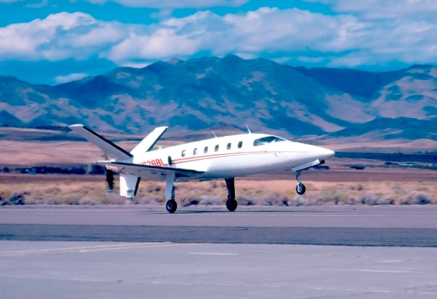
Lear Fan prototype E-001 lands at Stead Airport in Reno, Nevada after a test flight. Despite the nose-up attitude, note the ample clearance between the ventral fin and the runway. The Lear Fan certainly had the appearance of a capable, high-performance aircraft.

In the mid-1970s, and through his LearAvia Corporation located at Stead Airport in Reno, Nevada, Lear worked on a long-range business jet called the LearStar 600. Plans to develop and produce the aircraft were purchased by Canadair in April 1976. Lear and his team worked with Canadair to refine the aircraft, but engineers at Canadair did the same and changed many aspects of the original LearStar 600 design. Around March 1977, the team at LearAvia proposed an updated business jet design called the Allegro, which incorporated many composite components to increase the aircraft’s performance. Canadair was not interested in the Allegro, nor was it interested in Lear’s advice and meddling in the LearStar 600 design, which Canadair eventually developed as the Challenger 600.

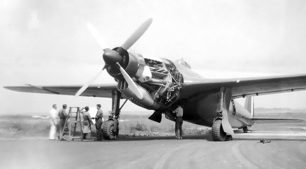
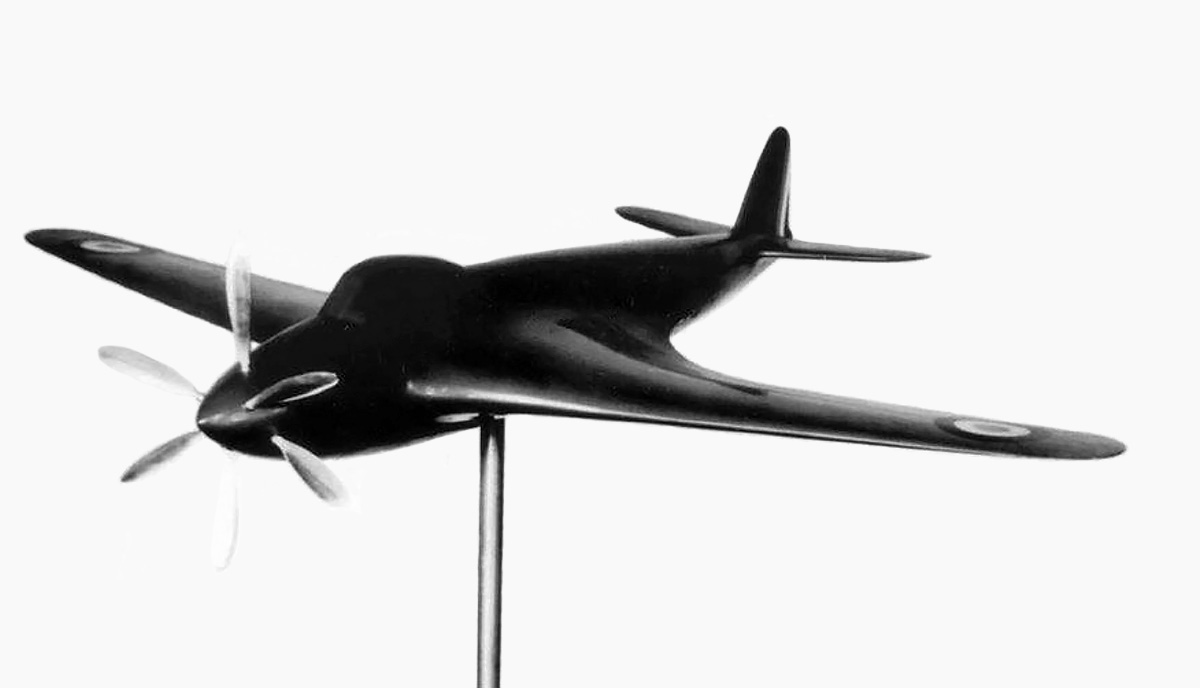
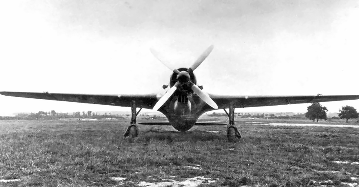
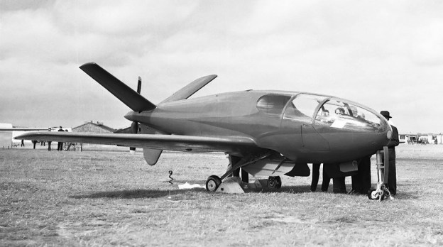
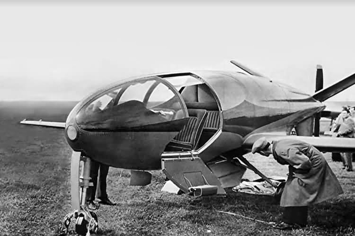
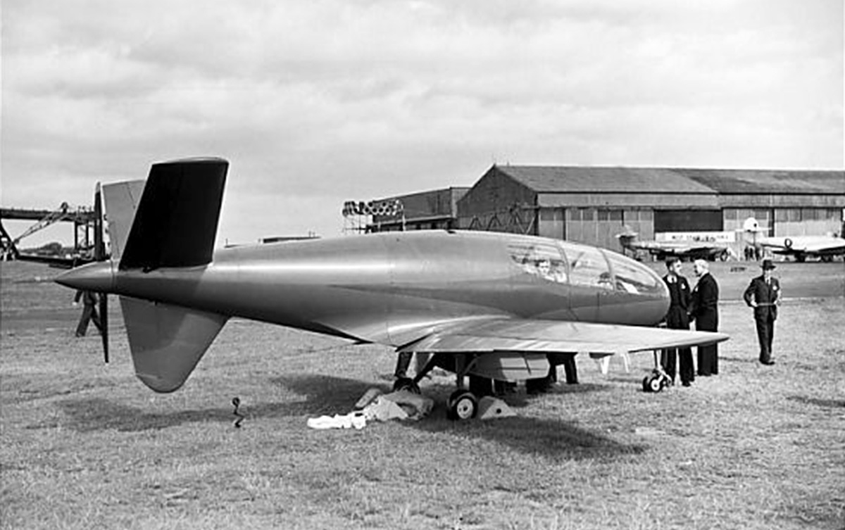
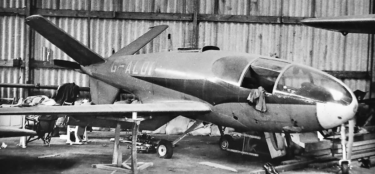
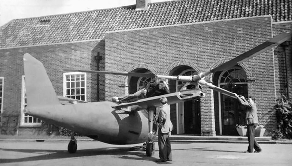
Since the 1950s, Lear had contemplated the design of an aircraft utilizing two turboprop engines in the fuselage that powered a single pusher propeller. The benefit of this centerline thrust configuration was that it would provide twin-engine reliability without any yaw effect from asymmetrical thrust in an engine-out situation. The basic design layout was similar to the Douglas XB-42 bomber prototype, which first flew on 6 May 1944, and the Planet Satellite light aircraft, which first flew in mid-1949. In early 1976, Lear discussed the pusher design with Richard Tracy, LearAvia’s chief engineer. Lear sought an aircraft that could carry six to eight passengers from Los Angeles to New York (2,465 miles / 3,967 km) at 400 mph (644 km/h) and at 41,000 ft (12,497 km) with two 500 hp (373 kW) engines. Lear and Tracy intermittently discussed the design for several months.

Lear-Fan-E003-in-flight-rear

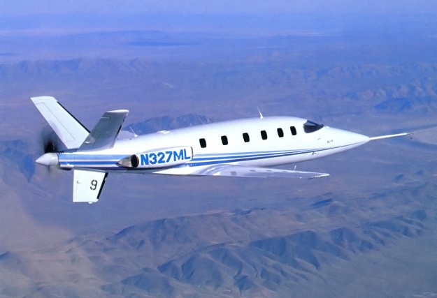
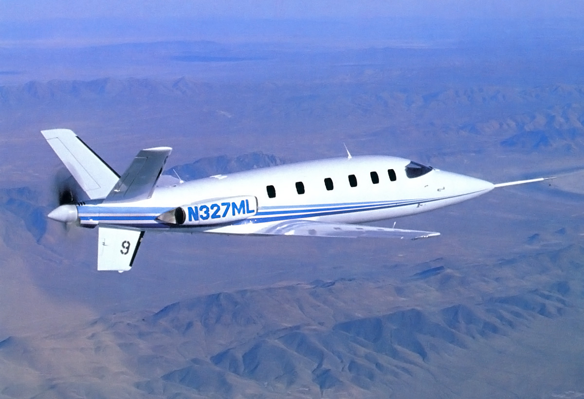
The second Lear Fan prototype E-003 was the primary aircraft for gathering fight test data. E-003 is seen here with its original N-number and blue paint. The number on the ventral fin signified the flight number. Note the data boom on the nose.

As the lack of progress with the LearStar 600 at Canadair grew frustrating for the LearAvia staff, Tracy reviewed the pusher design with Rodney Schapel, an aerodynamic engineer, and tasked him with making some preliminary drawings. Lear was initially not interested in the project and would chastise Schapel when he saw him working on the pusher design. However, as Canadair took control of the LearStar 600 and rejected the Allegro, Lear became more interested in the pusher aircraft and reviewed the design with Schapel and Tracy. Around April 1977, Lear decided that the pusher aircraft would be the company’s next design. The new aircraft was briefly called the Futura, but it quickly became the Lear Fan 2100.

The Lear Fan 2100 was a twin-engine, low-wing monoplane with tricycle landing gear. Depending on the configuration, the aircraft could accommodate one or two pilots and up to nine passengers in its pressurized cabin. Other configurations were considered, including a cargo version and an air ambulance that could accommodate two stretchers, each with a dedicated attendant. The Lear Fan was a revolutionary design in several regards. In addition to its two engines powering a single pusher propeller, Lear had decided that the entire aircraft would be made of a composite material. When compared to aluminum, the aircraft’s bonded graphite and epoxy composite structure was smoother, stronger, resistant to fatigue, would not corrode, could be molded into complex shapes, and was 40 percent lighter. The airframe was designed for a maximum loading of +6 and -4 Gs.

Lear-Fan-E001-and-E003-in-flight-side

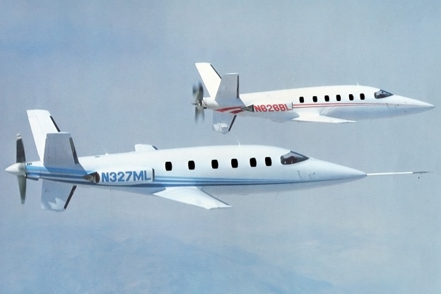
E-001 (right) and E-003 (left) in flight together. Note the fixed cooling air duct on E-003 between the propeller and ventral fin. E-001 had a different setup with a movable door. The “windows” for both aircraft were at least painted on in the photograph.

The aircraft’s fuselage was formed with close-spaced frames and longerons bonded to the outer skin. The skin was mostly four plies thick, but the thickness increased to eight or ten plies around window and door openings. The fuselage was made in six sections: upper and lower nose, upper and lower cabin, and upper and lower rear fuselage. The sections were bonded in an autoclave to form the entire fuselage structure. The fuselage had a slightly oval shape, and its interior had a maximum height of 4 ft 8 in (1.36 m) and a maximum width of 4 ft 10 in (1.47 m). The cabin was 12 ft 10 in (3.91 m) long and had a 50 cu ft (1.42 m3) baggage compartment that was accessible in flight at its rear.

Cabin access was via a door located on the left side of the fuselage and just forward of the wing. The first prototype had a split upper and lower door, but subsequent examples had a single door that folded down to form stairs for cabin entry. The passenger compartment originally had six windows on its right side and five windows on its left side. However, none of the prototype aircraft had their full allotment of windows, and some of the “windows” were painted on. It seems the window on the door was eventually omitted. Pressurization provided a nominal pressure differential of 8.3 psi (.57 bar), enabling an 8,000 ft (2,438 m) cabin altitude while cruising at a 41,000 ft (12,497 km) flight altitude. The steerable nosewheel retracted forward into the nose of the aircraft.

The single-piece, high-aspect wing had three continuous spars and was mated to the fuselage via six attachment points. Each wing spar was formed by two channel sections joined back-to-back on a honeycomb core. The upper and lower wing skins had 52 plies at their roots, with the thickness decreased to eight plies at the tips. The wing had four degrees of dihedral. The main landing gear had an 11 ft 8 in (3.56 m) track and retracted inward to be fully enclosed within the wing. Fuel tanks were integrated into the wing’s structure, and each wing housed up to 125 US gallons (104 Imp gal / 473 L) of fuel. Flaps extended along approximately 75 percent of the wing’s trailing edge, with ailerons extending almost to the wing tips. The landing gear and the flaps were hydraulically operated.

Lear-Fan-E003-in-flight-bottom

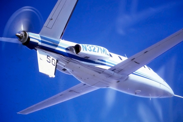
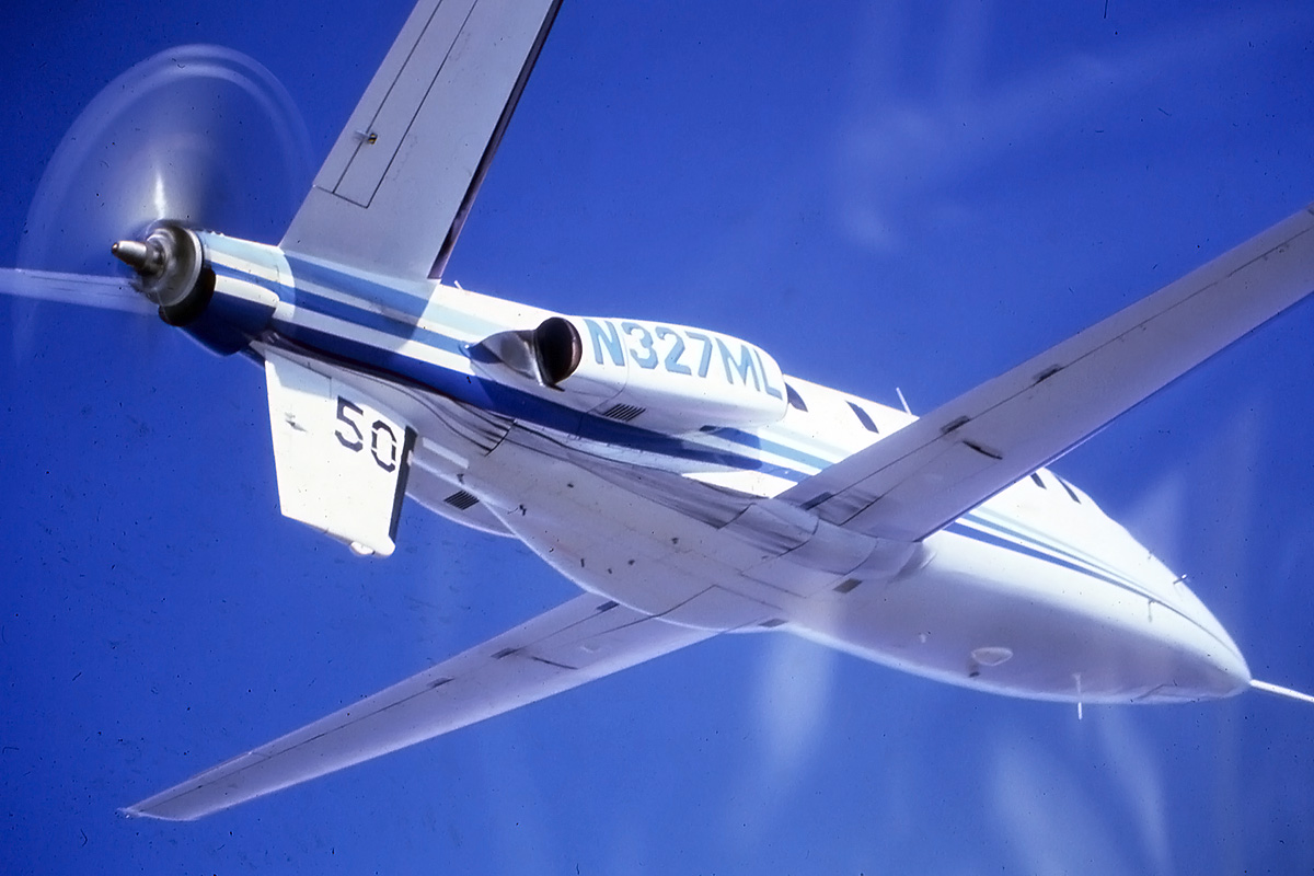
The underside of the Lear Fan as perhaps its least photogenic side. Even so, the view of E-003 illustrates the aircraft’s clean aerodynamic form, even with what appears to be a hydraulic leak from the right main gear. This was the aircraft’s 50th flight.

At the rear of the Lear Fan was a Y tail. The ventral fin had two spars, and a rudder was attached to its trailing edge. The structure of the fin was stressed for ground impacts to prevent the propeller from contacting the runway in case of an over-rotation during takeoff or a hard landing and incorporated a strike pad. Each of the two “butterfly” horizontal stabilizers had one spar. They had 35 degrees of dihedral, which increased the aircraft’s directional stability. The control surface on the horizontal stabilizer was a standard elevator for pitch control only. All normal flight controls were mechanically operated using cables and pushrods.

Originally, two Lycoming (probably LTS101) turboprop engines were to be used, but these were replaced with Pratt & Whitney Canada PT6B-35F engines early in the design phase. The PT6B-35F engines produced 850 shp (634 kW) but were flat-rated to 650 shp (485 kW) for the Lear Fan. The engines were positioned in the fuselage behind the wing’s trailing edge. A scoop on each side of the aircraft brought in air to the engine and expelled exhaust to the rear. The scoop was integral with a large service panel, the removal of which enabled access to the engine. A special mount held each engine in such a way that when the engine was disconnected from its drive shaft and other restrictions, the engine could be swung out for servicing and inspection. The pivot point was the mount at the front of the engine, and this action enabled access to the inner side of the engine.

A 6 ft (1.83 m) aluminum drive shaft with a graphite fiber cover extended from each engine to a combining gearbox at the rear of the aircraft. The gearbox was designed and built by Western Gear Corporation and was equipped with sprag overrunning clutches. If an engine failed, the good engine would continue to power the propeller. As originally designed, wax contained in the gearbox would melt to provide continuing lubrication in the event of oil loss. This method did not work as well as expected, and a back-up oil system was devised in 1984. Referred to as the “spin jet,” oil from a reserve tank was intermittently sprayed directly into the meshing gears. The gearbox was successfully run for over three hours with its main oil supply exhausted and its only lubrication provided by the “spin jet” system. An oil cooler was located under the gearbox. The gearbox had a .3125 propeller speed reduction, resulting in the propeller turning at 688 rpm when the engine’s drive shaft was rotating at 2,200 rpm. Originally, a 7 ft 6 in (2.29 m) diameter three-blade propeller built by Hartzell was to be used. However, a switch to a four-blade Hartzell propeller of the same diameter was made during the design phase when tests indicated that the four-blade propeller was less prone to vibration issues. The propeller was reversible and had 3 ft 1 in (.94 m) of ground clearance when the aircraft was on its landing gear.

Lear-Fan-E001-in-flight-rear

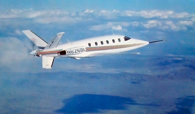
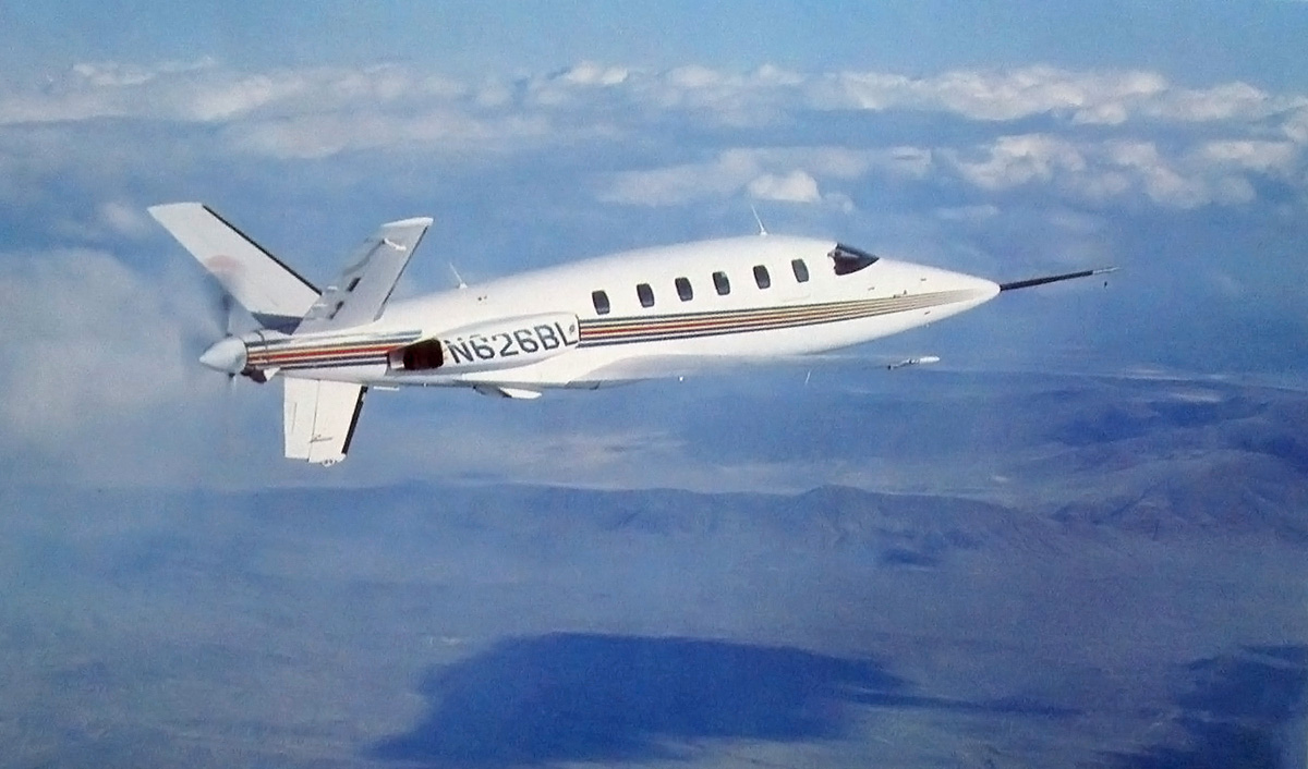
E-001 with its updated paint, which it still wears today. The two ducts under the aircraft were the inlet and exhaust for oil coolers. An open cooling air exit door is seen between the propeller and ventral fin. Subsequent prototypes used a fixed duct. Most images of E-001 in flight are without a spinner.

Although a Lear Fan brochure dating from 1979 lists the aircraft’s length as 38 ft 8 in (11.79 m), as originally built, the aircraft had wingspan of 39 ft 4 in (11.99 m), a length of 39 ft 7 in (12.07 m), and a height of 11 ft 6 in (3.51 m). The Lear Fan’s estimated performance was a top speed of 375 mph (604 km/h) at 39,000 ft (11,887 m), 403 mph (649 km/h) at 31,000 ft (9,449 m), and 414 mph (666 km/h) at 19,000 ft (5,791 m). Stalling speed was 90 mph (145 km/h). The aircraft had an initial climb rate of 3,550 fpm (18.0 m/s), and a ceiling of 41,000 ft (12,497 km). The Lear Fan had an empty weight of 3,650 lb (1,656 kg) and a gross weight of 7,200 lb (3,266 kg). At gross weight, the aircraft had a range of 1,630 miles (2,623 km) at 400 mph (644 km/h) and 2,300 miles (3,704 km) at 350 mph (563 km/h). On a single engine, the Lear Fan could takeoff, climb at 1,900 fpm (9.7 m/s), and execute a go-around. The aircraft’s single engine ceiling was 29,000 ft (8,839 m).

Lear was slowed down by health problems for a few years, but he was back to his old self in late 1977 as he tried to sell the Lear Fan concept to anyone who would listen. Lear made the decision to proceed with production prototypes rather than constructing a proof-of-concept vehicle first. While this decision could lead to cost savings and quicken development if everything went well, it would result in the exact opposite if things did not go well. By this time, Tracy had been replaced as chief engineer by Nicholas Anderson, and Schapel had been fired. Schapel had designed the aircraft’s original Y tail, but Lear wanted an inverted V tail. Schapel was let go over the disagreement. Ultimately, wind tunnel tests indicated that the Y tail was superior, and the Lear Fan reverted back to Schapel’s original tail design.

In early 1978, Lear’s health faltered again. He made arrangements for Lear Fan development to procced even if he were to die, but he desperately wanted to live long enough to see the prototype take to the air. In March, Bill Lear was diagnosed with leukemia, and he passed away on 14 May 1978. Some of his last words were urging that the Lear Fan be finished.

Lear-Fan-E003-in-flight-green

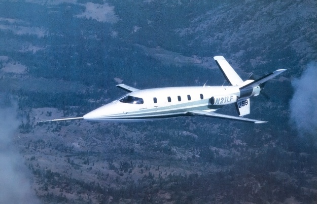
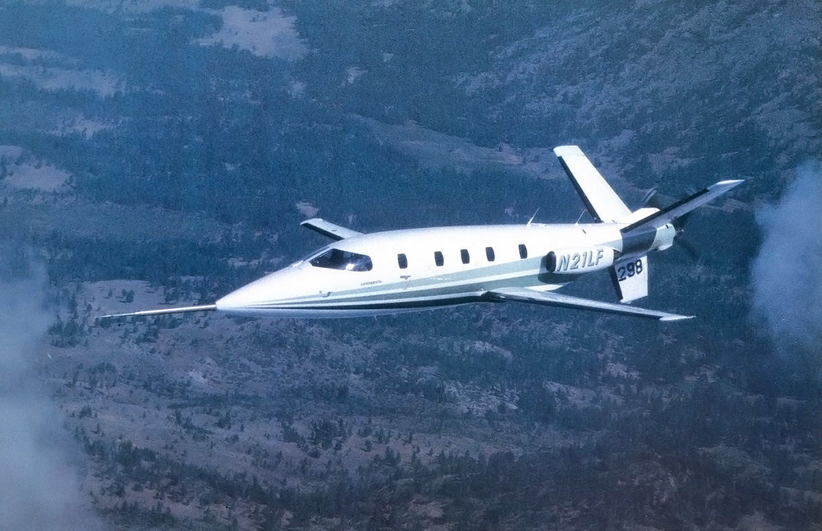
E-003 with its revised green paint and new N-number. The green paint was applied in honor of the Zoysia Corporation, the project’s major financial backer at the time. The number on the ventral fin indicates that this is the aircraft’s 298th flight. A spin chute is installed between the V tail. Although spin testing was never conducted, if needed, a shaped charge would have blown off the propeller before the chute was deployed.

Development of the Lear Fan did continue, and construction of a prototype was started in November 1978. Moya Lear, Bill’s wife, took over as the face of LearAvia. Progress on the aircraft’s untried propulsion system and gearbox, unusual layout, and all-composite structure proved slow and expensive. LearAvia’s financial resources were quickly depleted. In mid-1980, the company was restructured as Lear Fan Limited with the financial backing of investment firms and the British government. The agreement with the British government was that $25 million would go to the project, and another $25 million would be provided for Lear Fan production in Newtonabbey, near Belfast in Northern Ireland. British financial support would end if the prototype did not fly by the end of 1980. At the time, 126 aircraft were on order. Production was expected to start in 1982 and would create at least 1,200 jobs in Newtonabbey. Paramount for Lear Fan production was for the FAA (Federal Aviation Administration) to issue the aircraft a Certificate of Airworthiness. However, the Lear Fan’s all-composite construction was a first for a production aircraft, and certification was going to be a long and costly process.

Under the newly restructured company, the aircraft became the Lear Fan Limited LF 2100, and all prototypes were registered with the FAA as such. Lear Fan E-001 was registered as N626BL, for June 26 (his birthday) Bill Lear. On 31 December 1980, E-001 was rolled out of the hangar at Stead Airport to conduct taxi tests before its first flight. During a high-speed taxi test, the brakes were burned up and needed to be replaced. With 15 minutes of daylight left, the aircraft was preparing for takeoff when the sleeve of a pilot’s flight suit caught on the cockpit fire extinguisher handle, inadvertently activating it and forcing the flight to be scrubbed. The next day, 1 January 1981, the Lear Fan took to the air. The first takeoff was made by Hank Beaird in the left seat, with Dennis Newton in the right seat. The first landing was made by Newton in the left seat, with Beaird in the right seat. It was Beaird’s idea to switch seats so that both pilots had “firsts” during the Lear Fan’s initial flight. While the aircraft’s first flight was one day past the deadline, in the spirit of all that had been accomplished and by a Royal Decree signed by Queen Elizabeth, the British government declared that the Lear Fan made its first flight on 32 December 1980 and was still qualified for funding.

The remainder of 1981 was spent refining E-001 and continuing flight testing, building E-002 for use as a static test airframe, and building E-003. E-003 was registered as N327ML, for March 27 (her birthday) Moya Lear, and the aircraft was planned as the true workhorse for flight testing. With Lear Fan orders reaching 203 by June 1981 and 263 by early 1982, the future looked bright. E-001 had made 53 flights and had accumulated 78 flight hours by the start of 1982.

Lear-Fan-E009-Stead

The third Lear Fan prototype, E-009, seen outside the Lear Fan hanger at the Stead Airport. E-009 appears to have had all of its windows from the start. Although not quite apparent from the image, its colors were dark green and yellow on white.

The second prototype, E-003, had a new fuselage that was 12 in (.30 m) longer than that used on E-001, resulting in a length of 40 ft 7 in (12.37 m). The longer fuselage increased the cabin’s length to 13 ft 4 in (4.06 m) and the baggage compartment’s capacity to 53.7 cu ft (1.52 m3). The aircraft also incorporated some other minor modifications, such as a ventral duct at the extreme rear to bring in cooling air to the gearbox. E-003 made its first flight on 19 June 1982, most likely piloted again by Beaird and Newton. However, Lear Fan Limited had run out of money. The company was reorganized on 15 September 1982 as Fan Holdings, Inc, with the British investing $30 million and with the Zoysia Corporation, a consortium from Saudi Arabia, supplying $60 million. A major player in the Zoysia consortium was Prince Sultan bin Salman bin Abdulaziz Al Saud.

In December 1982, cracks in the wing were detected during static tests. Rather than undergoing a major wing redesign, the existing wing structure was reinforced. These modifications added weight and reduced the fuel load by 10 US gallons (8 Imp gal / 38 L), both of which decreased the aircraft’s range. At the start of 1983, 276 Lear Fans were on order. Flight testing of E-001 and E-003 resumed during the summer of 1983. In mid-July, the lower aft pressure bulkhead of the static test airframe E-002 failed during a pressurization test. On 20 July 1983, E-001 suffered an explosive decompression while at 25,000 ft (7,620 m). With the recent failure of E-002 on their minds, test pilots John Penny and Mark Gamache declared an emergency and brought the aircraft quickly and safely back to Stead Airport. The cause of the decompression could not be found, and the event marked the end of E-001’s flight career.

In December 1983, another test fuselage failed during pressure tests, and Fan Holdings Inc was running short on funds. At the time, Lear Fans had accumulated some 521 total flight hours. In March 1984, E-003 flew with its updated wing and fuselage. In April 1984, more fuselage issues were encountered. In June 1984, the Newtonabbey plant, which had been tooled up for production and had made various test parts, was shut down. Also in June 1984, the registration of E-003 was changed from N327ML to N21LF. Bill Lear’s will had focused on continuing Lear Fan development, but it created some potential conflicts of interest with the aircraft’s management team. Some of the Lear children filed suit in 1978 and 1979. Moya Lear became involved, and everything was settled as far as the courts were concerned in 1984. However, not all parties were appeased, and some consider the N-number change was done to spite Moya. Others feel it was to bring focus to the Lear Fan rather than to people behind the project.

Lear-Fan-E001-Museum-of-Flight---Kaiser

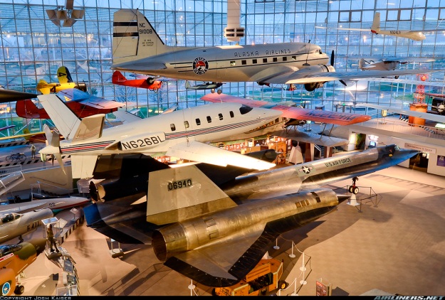
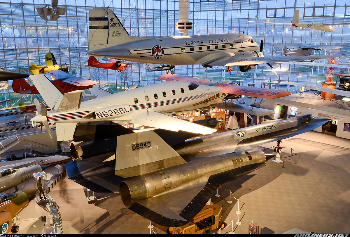
E-001 on display in the Museum of Flight in Seattle, Washington. The aircraft is in good company with the likes of a Douglas DC-3, Boeing 80, Gee Bee Z, and Lockheed M-21/D-21 in the background. (Josh Kaiser image via airliners.net)

Airframes E-004 through E-008 were all test articles for certification, but the continuous issues resulted in there being no end in sight for the certification process. In late 1984, Fan Holdings Inc was attempting to get the Lear Fan certified for unpressurised, VFR (Visual Flight Rules), day flight by January 1985. Certification for pressurized flight up to 25,000 ft (7,620 m) would follow in the spring of 1985, and certification up to 41,000 ft (12,467 m) would follow in mid-1985.

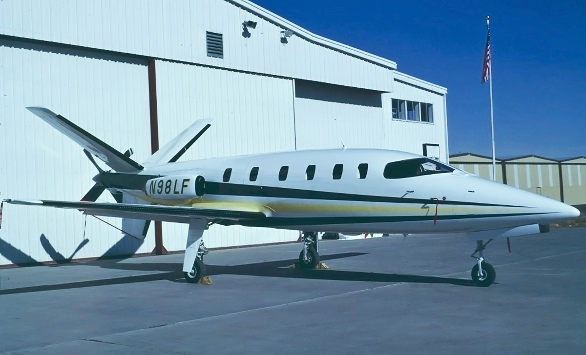
On 15 December 1984, airframe E-009 (N98LF) made it first flight with John Penny and Bob Jacobs at the controls. In April 1985, the aircraft was flown to William P. Hobby Airport in Houston, Texas to give Sultan bin Salman an orientation flight. At the time, Sultan bin Salman was undergoing training for his Space Shuttle flight abord Discovery, scheduled for June 1985. Most likely, it was hoped that the Lear Fan orientation flight would also result in additional financing from the Zoysia Saudi Arabian consortium, but it was not to be. On 25 May 1985, development of the Lear Fan was halted; all employees in Reno and Newtonabbey were let go, and all Fan Holdings Inc facilities were closed.

The Lear Fan’s revolutionary design and construction proved too much to overcome. The decision to develop the aircraft without a proof-of-concept proved costly, as numerous changes needed to be made. Problems had also been encountered with the gearbox, and its excessive wear was cited as the final blow to the program. After 200 hours of inspection, the FAA refused to issue a Certificate of Airworthiness for the Lear Fan. Some contend that the FAA set requirements for the Lear Fan that were two to three times more stringent than those for a comparable aluminum aircraft.

Lear-Fan-E009-Frontiers-of-Flight

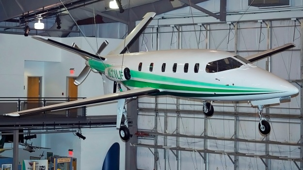
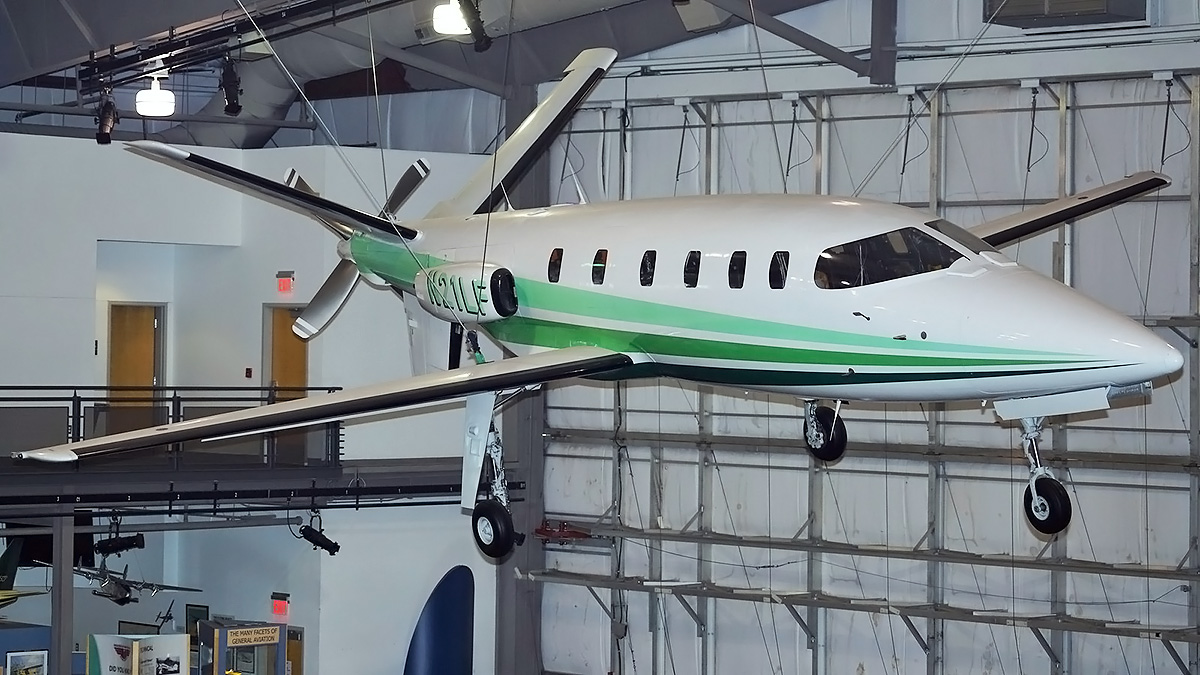
E-003 hangs on display in Frontiers of Flight Museum at Love Field in Dallas, Texas. Black pneumatic de-icing boots covered the Lear Fan’s leading edges. Hot exhaust from the engines would prevent the buildup of ice on the propeller. (Johnny Comstedt image via http://www.aviationmuseum.eu)

The final disclosed specifications for the Lear Fan were a wingspan of 39 ft 4 in (11.99 m), a length of 40 ft 7 in (12.37 m), and a height of 12 ft 2 in (3.71 m). The aircraft had a maximum speed of 414 mph (666 km/h) at 20,000 ft (6,096 m) and a stalling speed of 88 mph (142 km/h). Best economical cruise speed was 322 mph (518 km/h) at 40,000 ft (12,192 m), which gave a maximum range of 2,003 miles (3,224 km). The Lear Fan had an initial climb rate of 4,000 fpm (20.3 m/s) and a ceiling of 41,000 ft (12,497 km). The aircraft had an empty weight of 4,100 lb (1,860 kg) and a gross weight of 7,350 lb (3,334 kg). At gross weight, the Lear fan had a range of 1,782 miles (2,868 km). Single engine performance was a 1,300 fpm (6.6 m/s) climb rate and a 33,000 ft (10,058 m) ceiling.

Compared to the original flight specifications, the aircraft had become 450 lb (204 kg) heavier. While its maximum speed had increased by 14 mph, its maximum range at gross weight decreased by 670 miles (1,078 km), and its economical cruising speed decreased by 28 mph. After a peak of some 280 aircraft on order, most customers requested a refund as development dragged on. The entire Lear Fan project had consumed over $250 million.

Lear-Fan-E009-FAA-OKC

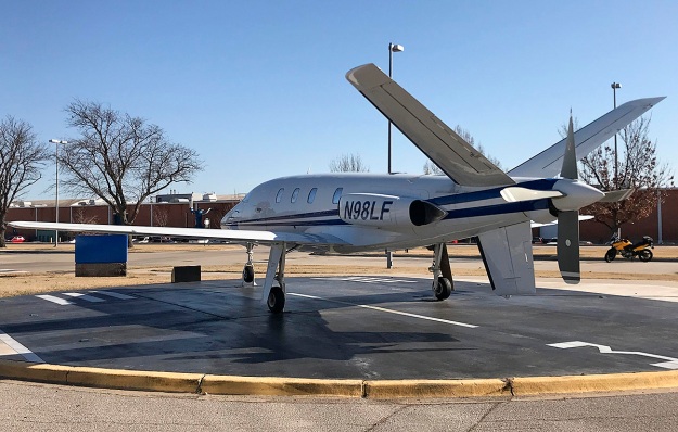
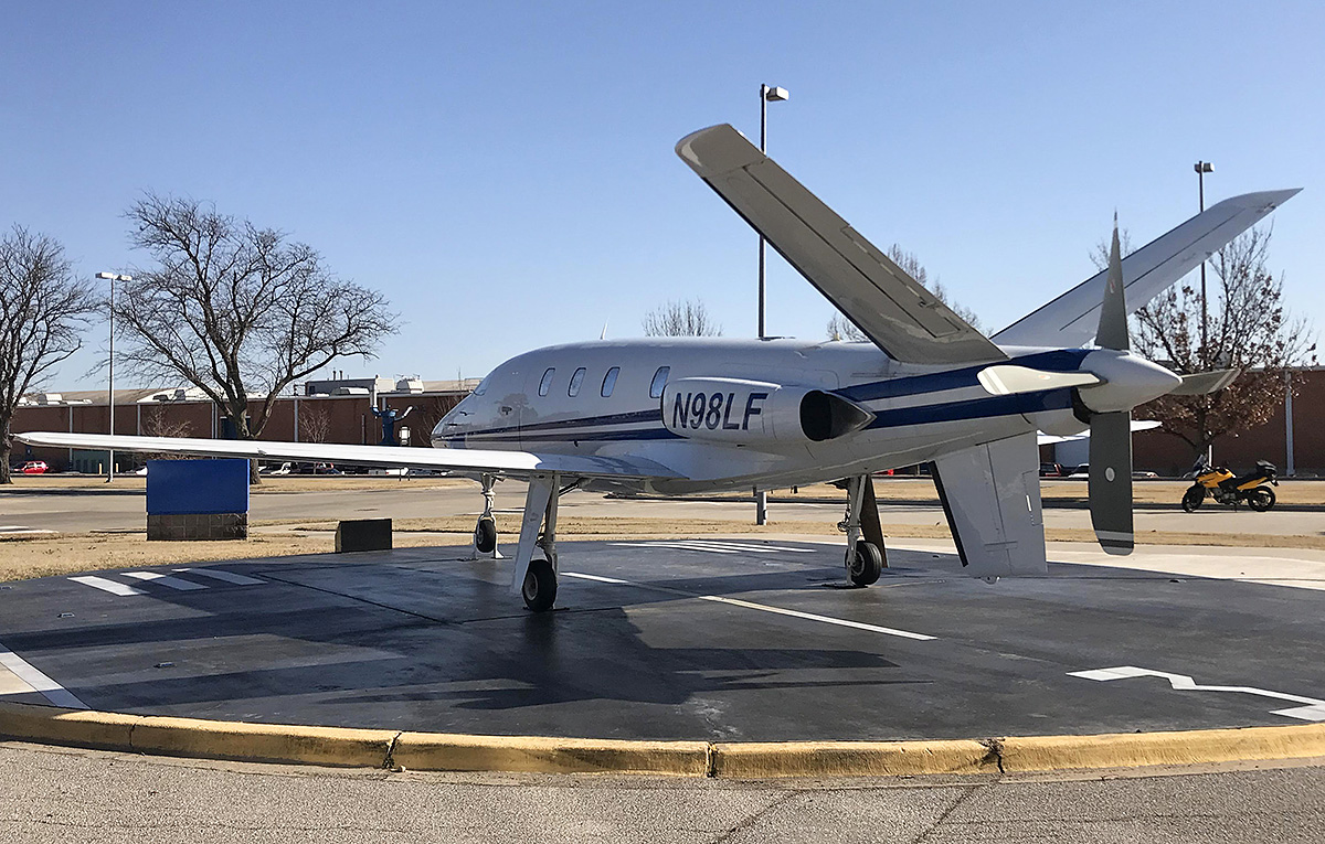
E-009 on display at the FAA’s Civil Aerospace Medical Institute in Oklahoma City, Oklahoma. The aircraft was previously in outside storage at the FAA facility and underwent a restoration starting in 2012. The new paint scheme was applied during the restoration. A dedication ceremony for the restored E-009 was held on 29 September 2015.

Years after their development was abandoned, Lear Fan airframes continued to be used to understand composites and develop techniques for their inspection. From November 1993 to October 1994, Northrup Grumman inspected the composite wing structure of E-009. The project was sponsored by US Department of Transportation and NASA to develop inspection techniques for composite aircraft. Although minor defects were detected, they were evaluated as not severe enough to impose a threat to the integrity of the wing structure. The final inspection report advised that composite assembly standards should be established to minimize defects and damage. It was noted that E-009 had about 230 flight hours.

The FAA acquired two Lear Fan test airframes, presumably from the E-004 to E-008 group. The airframes were tested at the Impact Dynamics Research Facility at the NASA Langley Research Center in Hampton, Virginia. The tests involved swinging the airframes into the ground from a 240 ft (73 m) gantry. This produced a 56 mph (90 km/h) forward velocity and an 1,860 fpm (9.4 m/s) descent rate at impact. The first aircraft was unmodified and tested in 1994. The fuselage broke in two above the wing, and the measured impact forces were greater than those recorded with comparable aluminum aircraft. The deformation and crumpling of aluminum absorbed some of the impact energy, while the composite structure of the Lear Fan absorbed less energy. The second airframe was modified with a composite, energy-absorbing subfloor and was tested on 15 October 1999. In addition, a plywood structure was built for the aircraft to collide with after ground impact. The fuselage cracked in a similar manner to the first airframe but the separation was less.

All three completed Lear Fan aircraft survive. E-001 (N626BL) hangs from the ceiling in the Great Gallery at the Museum of Flight on Boeing Field in Seattle, Washington. E-003 (N327ML/N21LF) hangs from the ceiling in the Frontiers of Flight Museum at Love Field in Dallas, Texas. E-009 (N98LF) was purchased by the FAA and is displayed outdoors at the Civil Aerospace Medical Institute, part of the Mike Monroney Aeronautical Center, adjacent to the Will Roger Airport in Oklahoma City, Oklahoma.

Lear-Fan-impact-test-1999

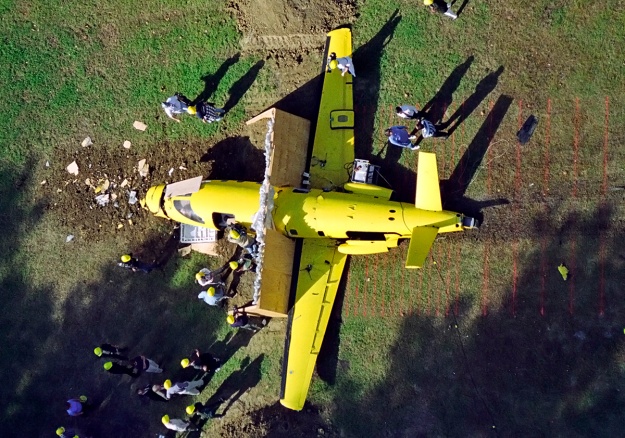
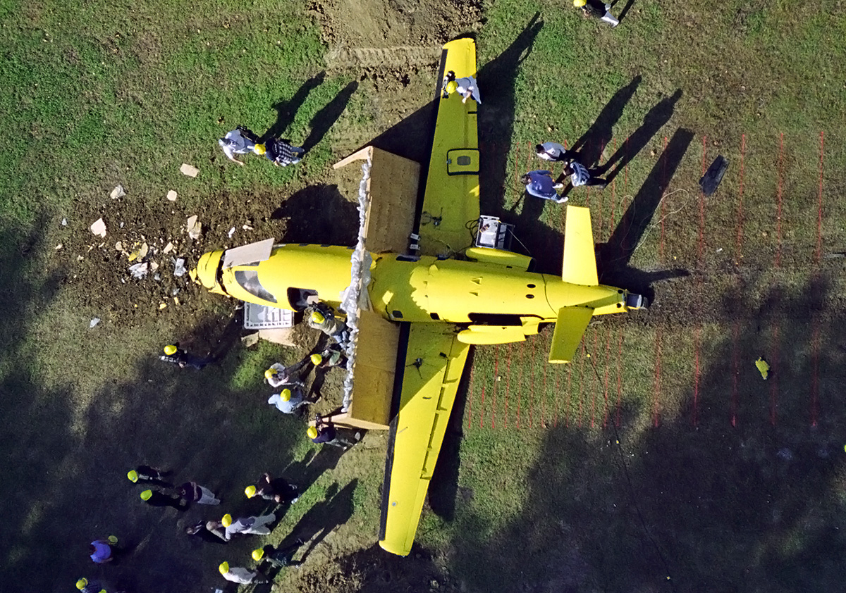
The second of two incomplete Lear Fan airframes owned by the FAA. The aircraft is pictured after its impact test on 15 October 1999. Off frame to the right is the concrete surface where the airframe made initial contact. It then slid onto the grass (note the red marker lines) and through the plywood barrier. A dirt berm was built-up on the left side of the plywood. Cracks in the fuselage can be seen near the plywood. The left engine cover with its integral duct have separated from the airframe. (NASA/Langley Research Center image)

Sources:
– Email correspondence with John Penny
Stormy Genius by Richard Rashke (1985)
Lear Fan (brochure) by LearAvia Corp (1979)
Lear Fan Propulsion System by Daniel E. Cooney (April 1980)
Jane’s All the World’s Aircraft by John WR Taylor (various editions 1979–1985)
– “Lear Fan 2100—first report” by Bill Sweetman, Flight International (10 January 1981)
– “Lear Fan collapses,” Flight International (8 June 1985)
– “Crosswind TakeoffEnterprise (video, 1984)
Structural Integrity Evaluation of the Lear Fan 2100 Aircraft by H. P. Kan and T. A. Dyer (May 1996)
Simulation of an Impact Test of the All-Composite Lear Fan Aircraft by Alan E. Stockwell (October 2002)
https://www.aviastar.org/air/usa/learavia_learfan.php

Planet-Satellite-Farnborough-front

Planet Satellite Light Aircraft

By William Pearce

John Nelson Dundas Heenan was born on 4 October 1892 in Altrincham, England. He became an engineer and worked for the family engineering firm Heenan & Froude in Manchester. Heenan left the family firm in 1935 when its parent company went bankrupt, and it was acquired by outside investors. Heenan worked for the British Air Ministry During World War II and cofounded the engineering consulting firm Heenan, Winn, and Steel (HW&S) in early 1946.

Planet-Satellite-cockpit-mockup

The cockpit mockup of the Planet Satellite on display in 1948. The major difference from the prototype is how the window panels above the door hinged up on the mockup, rather than sliding up as seen on the actual aircraft.

Like many others, Heenan believed that there would be a post-war boom in civil aviation with a huge need for light aircraft for private pilots. Working with others at HW&S, he designed an aircraft capable of carrying four to five passengers. Heenan decided that the aircraft should be built using a magnesium alloy with zirconium. However, due to a lack of experience with the metal, HW&S approached Magnesium Elektron Ltd to build the aircraft. Magnesium Elektron was owned by the Distillers Company Ltd, and its business had experienced a drastic contraction after the war. The Distillers Company was willing to consider options to expand Magnesium Elektron’s business and formed a partnership with HW&S to create Planet Aircraft Ltd. Planet Aircraft operated as a subsidiary of the Distillers Company to construct and produce the new aircraft, which was named Satellite. The aircraft was commonly referred to as the Planet Satellite.

The Satellite was a streamlined, low-wing, pusher monoplane with tricycle landing gear. The pusher configuration was chosen to reduce passenger cabin noise by isolating it from the engine and propeller. The two-piece fuselage was of monocoque construction and consisted of forward and rear sections. The magnesium fuselage was riveted together for the prototype aircraft, but production aircraft were to be welded. The fuselage was split just behind the wings for access to the engine, which was located aft of the passenger cabin and above the center wing section. A firewall separated the passenger cabin from the engine compartment.

Planet-Satellite-cockpit-construction

The Satellite’s forward fuselage section under construction. The firewall around the engine is visible. Baggage compartments that were accessible in flight existed behind the rear bench seat and on each side of the engine. The many rivets of the prototype would have given way to a welded structure on production aircraft.

The forward fuselage section incorporated the passenger cabin and was 4 ft 8 in (1.42 m) in diameter at its widest point. The pilot and copilot/front passenger sat behind an expansive windscreen that extended to the nose of the aircraft. A bench that could accommodate up to three passengers was behind the pilot’s seat. Cabin access was via two doors that folded down, one by the pilot’s seat and one by the copilot’s seat. As the door was opened downward, the armrest folded down to act as a step. The window above each door slid up toward the center of the fuselage.

An inverted, U-shaped magnesium keel reinforcement ran internally along the bottom of the forward fuselage section from the nose of the aircraft to the wing’s leading edge. At the leading edge, the keel became a single plate that extended to the wing’s trailing edge. The wings and main landing gear were attached to the plate. The pneumatically-operated landing gear was fully enclosed, with the nosewheel retracting to the rear into the keel and the main gear legs retracting forward and into the fuselage. A landing light was incorporated into the front of the aircraft, just above the nosewheel.

Planet-Satellite-Farnborough-front

The Satellite on display at the SBAC Farnborough Show in September 1948. The aircraft was not registered at the time, and was painted blue with a red accent. The main landing gear appears spindly and collapsed after the aircraft’s first hop.

To power the Satellite, buyers could choose between the 250 hp (186 kW) de Havilland Gipsy Queen 31 or the 145 hp (108 kW) de Havilland Gipsy Major 10. While both engines were inverted, inline, air-cooled designs, the six-cylinder Gipsy Queen had a 4.65 in (120 mm) bore, a 5.51 in (150 mm) stroke, a displacement of 621 cu in (10.18 L), and a weight of 510 lb (231 kg). The four-cylinder Gipsy Major had a 4.65 in (118 mm) bore, a 5.51 in (140 mm) stroke, a displacement of 374 cu in (6.12 L), and a weight of 312 lb (142 kg). The selected engine was affixed to a rail mount and could be slid out 18 in (.46 m) from the forward fuselage for maintenance once the rear fuselage was disconnected. A fan driven from the rear of the engine brought in cooling air via a duct atop the fuselage and expelled the heated air out the lower fuselage. Engine exhaust was also expelled in the same manner.

The wing had one main spar at its center and a false spar that supported the flaps and ailerons. The flaps ran along half of the wing’s trailing edge, with ailerons extending to the wingtips. Magnesium sheets 28 in (.71 m) wide were wrapped around the wing’s leading edge and extended to both the upper and lower trailing edges to form the wing skin. The wing had two degrees of dihedral, and each wing accommodated a 34 US gal (28 Imp gal / 127 L) fuel tank, for a total of 67 US gal (56 Imp gal / 255 L). With two additional wing tanks, the fuel capacity could be increased to 109 US gal (91 Imp gal / 414 L) for a long-range flight with a single pilot.

Planet-Satellite-Farnborough-cockpit

A good view illustrating access to the passenger cabin. Doors on each side of the aircraft folded down, and the armrest on the door became a step. The window panel above the door slid up. Note the long windscreen, and the landing light in the nose.

The forward and rear fuselage sections were joined via a quick-release locking “ring,” which Heenan had patented (GB 620,462: applied on 20 January 1947 and accepted on 24 March 1949). Control cables were automatically connected or disconnected in conjunction with the locking ring. The rear fuselage section incorporated the extension shaft, propeller, and Y tail.

The hollow extension shaft extended approximately 10 ft (3 m) from the engine to drive a two-blade, adjustable-pitch Aeromatic propeller at the extreme rear of the fuselage. The hollow steel shaft acted as an oil reservoir for the bearings that supported it. The propeller was 6 ft 6 in (1.98 m) in diameter. The ventral fin of the Y tail incorporated a rudder and a spring-loaded bumper to protect the propeller from ground impacts. The two “butterfly” horizontal stabilizers had 30 degrees of dihedral, which increased the aircraft’s directional stability. The Satellite’s control surfaces were of all-metal construction. The Planet Satellite had a wingspan of 33 ft 6 in (10.21 m), a length of 26 ft 3 in (8.00 m), and a height of 9 ft 3 in (2.82 m).

With a Gipsy Queen 31 engine, the aircraft had a top speed of 208 mph (335 km/h) at sea level and a stalling speed of 62 mph (100 km/h) at its maximum load. An economical cruise speed of 191 mph (307 km/h) was achieved at 3,500 ft (1,067 m), which resulted in a range of 1,000 miles (1,609 km) with a normal fuel load at maximum weight and 2,450 miles (3,943 km) with the extra fuel tanks and a single pilot. The Satellite had a 1,450 fpm (7.4 m/s) initial rate of climb and a ceiling of 22,000 ft (6,706 m). The aircraft had an empty weight of 1,600 lb (726 kg) and a maximum gross weight of 2,905 lb (1,318 kg). Fully loaded, the Satellite could take off in 570 ft (174 m). The Gipsy Queen-powered Satellite was offered for £3,500.

Planet-Satellite-Farnborough-rear

Rear view of the Satellite illustrates the aircraft’s Y tail. The line where the front and rear fuselage sections joined is visible just behind the wing’s trailing edge. The inlet for engine cooling air can be seen atop the fuselage.

With the significantly less powerful Gipsy Major 10 engine, the Satellite’s performance was reduced. The aircraft had a top speed of 173 mph (278 km/h) at sea level and a stalling speed of 54 mph (87 km/h) at its maximum load. An economical cruise speed of 161 mph (259 km/h) was achieved at 5,000 ft (1,524 m), which resulted in a range of 500 miles (805 km) with a normal fuel load at maximum weight and 2,150 miles (3,460 km) with the extra fuel tanks and a single pilot. The Satellite had a 950 fpm (4.8 m/s) initial rate of climb and a ceiling of 18,000 ft (5,486 m). The aircraft had an empty weight of 1,408 lb (639 kg) and a maximum gross weight of 2,280 lb (1,034 kg). Fully loaded, the Satellite could take off in 840 ft (256 m). The Gipsy Major-powered Satellite was offered for £2,500.

Detail design work on the Satellite started in April 1946. For Satellite construction, neither Planet Aircraft, Magnesium Elektron, or the Distillers Company had facilities to build the prototype aircraft. Magnesium Elektron contracted Redwing Aircraft Ltd to build two Satellite prototypes at their facility in Thornton Heath, near London. A mockup of the cockpit and forward fuselage section was completed in 1947, and the construction of two prototypes soon followed.

The first, nearly-complete Satellite made its public debut at the SBAC (Society of British Aircraft Constructors) Farnborough Show in September 1948. The aircraft was registered as G-ALOI on 26 April 1949. The Satellite was moved to Blackbushe Aerodrome, near Farnborough, for flight trials. Flight testing was to be conducted by Hugh Joseph “Willie” Wilson, who had resigned from the Royal Air Force as a Group Captain to serve as a director with Planet Aircraft. On 7 November 1945, Wilson had established a new World Air Speed Record at 606.262 mph (975.675 km/h) in a Gloster Meteor.

Planet-Satellite-Redhill-derelict

The Satellite sits derelict in a hangar at Redhill. The aircraft wears its G-ALOI registration, and a scoop to augment the intake of cooling air has been installed. The scoop was probably fitted after the first round of ground tests. Note that the gear doors are closed despite the landing gear being deployed. This did not appear to be possible from the Farnborough images. Perhaps the gear doors seen at Farnborough were mockups or a redesign occurred.

Wilson took the Satellite for high-speed taxi tests and did a tentative hop in the aircraft. Upon settling back on the ground, the landing gear promptly collapsed. The Satellite was repaired, and Wilson restarted the test program. Again at Blackbushe Aerodrome, Wilson took the aircraft to about 20 ft (6 m) above the runway. This time the landing was uneventful. However, a crack in the magnesium keel was discovered when the aircraft was inspected after the flight. Analysis of the crack indicated that the Satellite’s magnesium structure was severely understressed and would need an extensive rebuild to bring it into tolerance of its expected flight regime. The British Air Registration Board required that the aircraft be restressed before any further flights were made.

Although Heenan was an engineer, he was not an aeronautical engineer, and the Satellite was his first aircraft design. He once said that only 400 drawings were made during the Satellite’s design phase, compared to the roughly 3,000 drawings that would be expected for a comparable aircraft. With the design now coming up short, another £40,000 would be needed to resolve the Satellite’s deficiencies. The Distillers Company had already invested over £100,000 and withdrew further funding. The Satellite was moved to Redhill Aerodrome south of London, where it sat and slowly deteriorated until 1958, when it was finally scrapped.

The second Satellite prototype was registered as G-ALXP in 1950, but it was never completed. G-ALXP’s mostly-finished fuselage was later used by Firth Helicopters as the basis for the FH.01/4 Atlantic helicopter, a twin-rotor design which was built in 1952. The FH.01/4 Atlantic was also designed by HW&S, but it never flew and was eventually scrapped in the 1960s. Most likely by coincidence, the basic layout of the Planet Satellite would be resurrected in the late 1970s as the Lear Fan 2100, another unconventional aircraft constructed of unconventional materials in hopes of revolutionizing private air travel.

Planet-Satellite-Firth-FH1

The fuselage of the second Satellite prototype was used for the Firth FH.01/4 helicopter, which never flew. The helicopter was donated to the College of Aeronautics at Cranfield in 1955, which is probably when the image above was taken.

Sources:
The Planet Satellite by Planet Aircraft Ltd (cira 1948)
Jane’s All the World’s Aircraft 1949–50 by Leonard Bridgman (1949)
– “Heavenly Body” by Don Middleton, Aeroplane Monthly (October 1983)
– “Ones That Got Away: Planet Satellite” by Mike Jerram, Wingspan International (March/April 2001)
Aircraft Engines of the World 1948 by Paul H. Wilkinson (1948)
– “Improvements in and relating to Aeroplanes” by John Nelson Dundas Heenan, GB patent 620,462 (applied 20 January 1947)
https://www.secretprojects.co.uk/threads/planet-aircraft-ltd-and-firth-helicopter-prototypes.1170/

Lockheed-1249-R7V-2-in-flight-no-wing-tanks

Lockheed Model 1249 Turboprop Super Constellation

By William Pearce

In 1938, the Lockheed Corporation in Burbank, California began design work on a large commercial airliner intended to outperform other transports then in service. Initially known as the Model 44 Excalibur, the aircraft’s design changed as feedback provided by Pan American Airways was evaluated. In 1939, Transcontinental and Western Air (TWA) approached Lockheed in search of an aircraft with performance superior to that of the planned Model 44. Lockheed decided to redesign its airliner based on TWA’s requirements, and the new design became the Model 049 Constellation (originally Model 49 and known as Excalibur A).

Lockheed-1249-R7V-2-Super-Constellation

The Lockheed Model 1249 was a turboprop-powered Super Constellation originally ordered by the US Navy as the R7V-2. The aircraft was the fastest of the Constellation series by far, but other turboprop and jet aircraft were favored by all parties.

The Model 049 Constellation was an all-metal, low-wing aircraft with tricycle landing gear. The airliner was powered by four 2,200 hp (1,641 kW) Wright R-3350 engines and carried 60 passengers in its pressurized cabin. The Model 049 had a 123 ft (37.5 m) wingspan and was 95 ft 2 in (29.0 m) long and 23 ft 8 in (7.2 m) tall. The aircraft’s tail had three vertical stabilizers with rudders to keep the aircraft’s overall height down so that it would fit in TWA’s existing hangars. The Model 049 had a top speed of 329 mph (529 km/h) at sea level, a cruising speed of 275 mph (443 km/h) at 20,000 ft (6,096 m), an initial climb rate of 1,620 fpm (8.2 m/s), and a range of 2,290 miles (3,685 km) with a maximum payload of 18,400 lb (8,346 kg). The aircraft had an empty weight of 55,345 lb (25,104 kg) and a maximum weight of 86,250 lb (39,122 kg).

In 1940, the design of the Model 049 was mostly finalized, and three airlines had placed orders for a total of 84 aircraft (30 of these were long-range Model 349s). In May 1941, the United States Army Air Corps ordered 180 Model 349s to be used as transports. Lockheed tooled-up for aircraft production, and construction of the first Model 049 was underway when the United States entered World War II after the bombing of Pearl Harbor on 7 December 1941. With the United States at war, production priorities shifted, and all of the aircraft intended for the airlines would be completed as C-69s, the military designation for the Model 049/349.

Lockheed-1249-R7V-2-under-wing

Installation of the Pratt & Whitney T34 turboprop engines onto the Super Constellation airframe was well-executed. The tight-fitting cowling was much smaller than those needed to cover the larger-diameter R-3350 piston engine. The aircraft’s main gear was unchanged, which resulted in an awkward hump under the No. 2 and 3 engines. Note the wide cord of the three-blade propeller.

The C-69 received a low priority compared to Lockheed’s other commitments, and the prototype made its first flight on 9 January 1943. Only 15 C-69s were completed by the end of the war. After the war, Lockheed again focused on the Constellation for airline use, and new orders were received. In May 1945, Lockheed made use of new 2,500 hp (1,864 kW) R-3350 engines and designed the Model 649 and the Model 749, which had increased range. The United States Air Force also used the Model 749 as the C-121A. The Model 749 had a top speed of 358 mph (576 km/h) at 19,200 ft (5,852 m), a cruising speed of 304 mph (489 km/h) at 20,000 ft (6,096 m), an initial climb rate of 1,280 fpm (6.5 m/s), and a range of 1,760 miles (2,834 km) with a payload of 16,300 lb (7,394 kg). The aircraft had an empty weight of 58,970 lb (26,748 kg) and a maximum weight of 107,000 lb (48,534 kg).

In late 1949, Lockheed investigated ways to improve the Constellation’s performance and keep the aircraft on the frontline of airline service. The result was the Model 1049 Super Constellation, which had two new fuselage sections added that increased the aircraft’s length by 18 ft 5 in (5.6 m). In addition, 2,700 hp (2,013 kW) R-3350 engines were installed, and the height of the vertical stabilizers was increased by 1 ft 3 in (.38 m). The aircraft could accommodate up to 92 passengers. The Model 1049 was 113 ft 7 in (34.6 m) long, 24 ft 9 in (7.6 m) tall, had a top speed of 338 mph (544 km/h) at sea level, a cruising speed of 302 mph (485 km/h) at 20,000 ft (6,096 m), an initial climb rate of 1,100 fpm (5.6 m/s), and a range of 2,880 miles (4,635 km) with a payload of 18,800 lb (8,528 kg). The aircraft had an empty weight of 69,210 lb (31,393 kg) and a maximum weight of 120,000 lb (54,431 kg). The Model 1049 made its first flight on 13 October 1950. The Model 1049B was a military transport version of the Super Constellation, designated R7V-1 (originally R7O-1) for the US Navy and C-121C for the US Air Force.

Lockheed-1249-R7V-2-in-flight-no-wing-tanks

The first R7V-2 (BuNo 131630) seen on a test flight without the wingtip fuel tanks. The Constellation-series of aircraft is known as one of the more graceful airframes, and the turboprop engines made the aircraft that much more impressive.

From the start of the Model 1049’s design, Lockheed had envisioned using 3,250 hp (2,424 kW) R-3350 Turbo Compound (TC) engines, which used three power recovery turbines to harness energy from the exhaust and feed it back to the crankshaft via fluid couplings. However, Wright’s development of the engine lagged behind that of the aircraft. The R-3350 TC engines were first incorporated into the Model 1049C, which made its first flight on 17 February 1953. The pinnacle of the Super Constellations was the Model 1049G, powered by 3,400 hp (2,535 kW) R-3350 TC engines. The aircraft made its first flight on 7 December 1954. The Model 1049G had a top speed of 370 mph (595 km/h) at 20,000 (6,096 m), a cruising speed of 310 mph (499 km/h) at 20,000 ft (6,096 m), an initial climb rate of 1,165 fpm (5.9 m/s), and a range of 4,165 miles (6,704 km) with a payload of 18,300 lb (8,301 kg). The aircraft had an empty weight of 73,016 lb (33,120 kg) and a maximum weight of 137,500 lb (62,369 kg).

The US Navy had been instrumental in supporting Wright’s development of the turbo compound engine, but in the early 1950s, the turboprop engine was making its way onto the aviation scene. In June 1950, Lockheed considered a turboprop-powered Super Constellation airliner as the Model 1149, but the design did not procced. In November 1951, Lockheed proposed to the Navy a turboprop R7V-1 (Model 1049B) powered by Pratt & Whitney T34 turboprop engines. The Navy was interested, and Lockheed proceeded with design work on the turboprop Super Constellation as the Model 1249. The Navy ultimately amended its R7V-1 order to include two airframes converted to turboprop-power. These aircraft were designated R7V-2 by the Navy and carried the Lockheed serial numbers 4131 and 4132 and the Navy BuNos 131630 and 131631.

Lockheed-1249-R7V-2-no-wing-tanks

Side view of the R7V-2 shows the reinforcements on the rear fuselage above and below the large cargo door, which hinged up. The turboprop aircraft used standard Super Constellation fuselages, and most were reused on piston-powered aircraft once their days of testing were over.

Two additional airframes were ordered in May 1953. They carried the Lockheed serial numbers 4161 and 4162 and Navy BuNos 131660 and 131661. In October 1953, BuNos 131660 and 131661 were slated to be completed as YC-121Fs for the Air Force and were also assigned Air Force serial numbers 53-8157 and 53-8158. The YC-121F was the Lockheed Model 1249A. Since the order originated with the Navy, all four turboprop Super Constellations carried the Navy designation R7V-2, with the last two also assigned the Air Force designation. All four aircraft were purely intended to test the serviceability of the turboprop engine.

The Model 1249 was based on the Model 1049B, with a modified wing and new engines. The R-3350-powered Constellations had the engine nacelle’s centerline mounted below the wing. The Model 1249 had the engine nacelle’s centerline mounted above the wing, and the nacelle extended back to the wing’s trailing edge. Exhaust from the turboprop engine was expelled from the back of the nacelle and generated thrust. The Model 1249 could also accommodate removable 600 US gallon (500 Imp gal / 2,271 L) wingtip tanks that were first installed on Navy Super Constellations and later used by airlines. Additional fuselage fuel tanks were fitted, and the landing gear was strengthened.

Lockheed-1249-YC-121F-131660-over-Pacific-Palisades

The first YC-121F, still with Navy BuNo 131660 painted on the tail, seen on a test flight over Pacific Palisades, just north of Santa Monica, California. Note the large, removable wingtip fuel tanks.

The T34 turboprop was an axial-flow engine that consisted of a 13-stage compressor powered by a three-stage turbine. Sources indicate that the R7V-2s for the Navy used T34-P-12 engines, while the YC-121Fs for the Air Force used T34-P-6 engines. The T34-P-12 produced 5,005 shp (3,732 kW) and 1,360 lbf (6.05 kN) of thrust, for a total of 5,550 eshp (4,139 kW) at 11,000 rpm for takeoff power. Continuous power for the T34-P-12 was 4,210 shp (3,139 kW) and 1,165 lbf (5.18 kN) of thrust, for a total of 4,675 eshp (3,486 kW) at 10,500 rpm.

The T34-P-6 produced 5,500 shp (4,101 kW) and 1,250 lbf (5.56 kN) of thrust, for a total of 6,000 eshp (4,474 kW) at 11,000 rpm for takeoff power. Continuous power for the T34-P-6 was 4,750 shp (3,542 kW) and 1,125 lbf (5.57 kN) of thrust, for a total of 5,200 eshp (3,878 kW) at 10,750 rpm. Each engine turned a three-blade Hamilton Standard A-3470 propeller at .0909 engine speed. The propeller was 15 ft in (4.57 m) diameter, and each blade was 24 in (610 mm) wide.

The Model 1249 had a 117 ft (35.7 m) wingspan without wingtip fuel tanks and a 119 ft (36.3 m) wingspan with wingtip fuel tanks. The aircraft was 116 ft 2 in (35.4 m) long and 25 ft 6 in tall (7.8 m). The Model 1249 had a top speed of 444 mph (715 km/h) at 15,000 ft (4,572 m) and could maintain 420 mph (676 km/h) at 25,000 ft (7,620 m). The aircraft had an initial climb rate of 4,600 fpm (23.4 m/s) at maximum power and 2,310 fpm (11.7 m/s) at normal power. The Model 1249’s ceiling was 32,900 ft (10,028 m) at maximum power and 26,400 ft (8,047 m) at normal power. The aircraft’s range was 2,230 miles (3,589 km) with a payload of 24,210 lb (10,981 kg), and it had an empty weight of 72,387 lb (32,834 kg) and a maximum weight of 148,540 lb (67,377 kg). The Model 1249 could accommodate 106 passengers and four crew members for short flights, 87 passengers and 15 crew members for long flights, or 35,500 lb (16,103 kg) of cargo. For medical evacuations, the aircraft could accommodate 73 litters, four attendants, and four crew members.

Lockheed-1249-YC-121F-58-8258

The second YC-121F, Air Force serial number 53-8158, seen with flaps and gear extended. Note the exhaust outlet at the rear of the engine nacelles.

The Model 1249 / R7V-2, BuNo 131630, made its first flight on 1 September 1954. The aircraft was not initially fitted with the wingtip tanks, and it was accepted by the Navy on 10 September 1954. The second R7V-2 soon followed and was accepted by the Navy on 30 November 1954. The Navy put the R7V-2 aircraft through various tests. A top speed of 479 mph (771 km/h) was achieved in a slight dive, and the aircraft took off overweight at 166,400 lb (75,478 kg). However, the R7V-2’s career was short. In December 1956, and with just 109 total hours, BuNo 131630 was put into storage at Naval Air Station (NAS) Litchfield Park in Arizona. The aircraft was struck off charge in April 1959 and provided spare parts for other Constellations.

In late 1956, BuNo 131631 was loaned back to Lockheed as an engine testbed for the L-188 Electra airliner and later the P-3 Orion maritime patrol aircraft. At the time, BuNo 131631 had accumulated 120 hours of operation. Rohr Aircraft in Chula Vista, California removed the T34 engines and replaced them with Allison 501-D (T56) engines in new nacelles intended for the Electra. The 501-D produced 3,460 shp (2,580 kW) and 726 lbf (3.23 kN) of thrust, for a total of 3,750 eshp (2,796 kW) for takeoff power. The engines turned four-blade Aeroproducts 606 propellers that were 13 ft 6 in (4.11 m) in diameter. The modified aircraft was nicknamed ‘Elation,’ a combination of Electra and Constellation. Elation made its first flight in July 1957 and was used until July 1959 when it was damaged at Palmdale, California. With 882 hours, BuNo 131631 was delivered to NAS Litchfield Park. In May 1960, the aircraft was sold to California Airmotive. The fuselage and some other parts were used to rebuild 1049G Super Constellation N7121C, and the remainder was scrapped. N7121C went through various air cargo owners until it was scrapped in March 1968.

Lockheed-1249-131631-4132-Elation

Lockheed serial 4132, the second R7V-2 (BuNo 131631), fitted with Allison 501-D engines to test their installation for the L-1888 Electra. Known as the Elation, the aircraft flew more with the Allisons than it did with its original Pratt & Whitney engines. Note the four-blade propellers.

The Model 1249A / YC-121F, serial no 53-8157, made its first flight on 5 April 1955 and was accepted by the Air Force in July. The second aircraft, serial number 53-8158, took to the air in August 1955. Both YC-121Fs were assigned to the 1700th Test Squadron of the Military Air Transport Service, based at Kelly Air Force Base in San Antonio, Texas. In April 1956, a YC-121F set a point-to-point speed record, traveling the 1,445 miles (2,326 km) between Kelly, Texas and Andrews Air Force Base, Maryland in 2 hours 53 minutes, an average of 501.16 mph (806.54 km/h). Between 25 and 26 January 1957, another record was set flying from Long Beach, California to Andrews Air Force Base, Maryland. The 2,340-mile (3,766-km) route was covered in 4 hours 43 minutes at an average speed of 496.11 mph (798.41 km/h). Both record flights were most likely made by 53-8157.

In June 1957, 53-8158 was assigned to McClellan Air Force Base in Sacramento, California; 53-8157 followed a year later. In February 1959, the two YC-121Fs were placed in storage at Davis Montham Air Force Base in Tucson, Arizona. Both aircraft were sold to the Flying Tiger Line 1963. The fuselages of the two YC-121Fs were used with wings, engines, and tails from two 1049Gs and pressed into cargo transport service in 1963. In 1966, both aircraft were sold to North Slope Aviation Company in Alaska. Serial number 53-8158 (N174W) was written off in May 1970. Serial number 53-8157 (N173W) was sold to Aviation Specialties and written off in June 1973.

Along with the military versions, Lockheed had designed a turboprop Super Constellation airliner in 1952 designated as the Model 1249B. The aircraft was planned to have a maximum speed of 451 mph (726 km/h) and a maximum range of 4,125 miles (6,639 km). However, the 1249B was not pursued, and the L-188 Electra eventually took its place.

Lockheed-1249-Super-Constellation-ad

An ad for the turboprop Super Constellation as Lockheed made a light push to interest airlines in the concept. There were no takers, and Lockheed developed the L-188 Electra instead.

Sources:
The Lockheed Constellation by Peter J. Marson (2007)
Lockheed Constellation by Curtiss K. Stringfellow and Peter M. Bowers (1992)
Lockheed Aircraft since 1913 by René J. Francillon (1987)
Lockheed C-121 Constellation by Steve Ginter (1983)
Characteristics Summary YC-121F by US Air Force (1 April 1957)
Lockheed Constellation by Dominique Breffort (2006)
https://www.thisdayinaviation.com/tag/lockheed-yc-121f/
http://www.conniesurvivors.com/1-QandA.htm

Martin-XB-51-flight-top

Martin XB-51 Attack Bomber

By William Pearce

In February 1946, the United States Army Air Force (AAF) sought design proposals for an attack aircraft to replace the Douglas A-26 Invader. The Glenn L. Martin Company (Martin) responded with its Model 234, a straight-wing aircraft of a rather conventional layout, except that the engine nacelle on each wing housed a turboprop and a turbojet engine. The Model 234 had a crew of six and was forecasted to carry 8,000 lb (3,629 kg) of ordinance over 800 miles (1,287 km).

Martin-XB-51-flight-top

The Martin XB-51 was a unique attack bomber designed at the dawn of the jet age. The first prototype is seen here with its original tail. Note the inlet for the fuselage-mounted engine. The dark square behind the canopy is a window over the radio operator. (Martin/USAF image)

Martin was awarded a contract to develop the Model 234 on 23 May 1946, and the aircraft was designated XA-45. A few weeks later, the AAF decided to discard the “Attack” category, and the XA-45 was subsequently redesignated XB-51. The AAF then requested new requirements for the XB-51 with an emphasis on speed. The AAF’s new desired specifications for the A-26 replacement was a top speed of 640 mph (1,030 km/h) and the ability to carry 4,000 lb (1,814 kg) of ordinance over 600 miles (966 km). The new requirements necessitated a complete redesign of the XB-51, which Martin completed and submitted to the AAF in February 1947. After slight modifications, the design was somewhat finalized by July 1947. The AAF ordered two prototypes, which were assigned serial numbers 46-685 and 46-686.

The Martin XB-51 was a radical departure from the firm’s previous aircraft designs. The XB-51 was an all-metal aircraft that featured a relatively large fuselage supported by relatively small swept wings. The aircraft had a crew of two and was powered by three General Electric J47-GE-13 engines, each developing 5,200 lbf (23.13 kN) of thrust. Two of the engines were mounted on short pylons attached to the lower sides of the aircraft in front of the wings. The third engine was buried in the extreme rear of the fuselage.

Martin-XB-51-rollout

The XB-51 with its flaps up and its wing at an incidence of three degrees as the aircraft is rolled out on 4 September 1949. The circle on the side of the fuselage just behind the cockpit is a side window for the radio operator. There is no window mirrored on the left side of the aircraft. Note that the intake for the fuselage-mounted engine has its cover rotated closed. (Martin/USAF image)

The pilot sat in the front of the aircraft under what appeared to be a small canopy in contrast to the large fuselage. Behind the pilot and completely within the fuselage was the radio operator, who was also in charge of the short range navigation and bombing (SHORAN) system. The crew compartment was pressurized, and access was provided by a door on the left underside of the fuselage, between the pilot and radio operator’s stations. In case of an emergency, both crew were provided with upward firing ejection seats.

The engine housed in the rear fuselage was fed by an inlet duct located atop the fuselage. A rotating assembly was installed forward of the inlet to either cover the inlet with an aerodynamic fairing when the engine was not in use, or rotate to provide a duct to feed air to the engine. The rear engine could be shut down in flight to extend the aircraft’s range. When not in use, a door in the intake duct prevented the back flow of air through the rear engine. Large doors swung open beneath the fuselage to access the rear engine.

Martin-XB-51-color

The first XB-51 with flaps down and its wing at an incidence of 7.5 degrees. Note that only one of the wingtip outrigger gears is touching the ground. (Martin/USAF image)

Mounted above the rear engine was the vertical stabilizer, with the horizontal stabilizer mounted to its top. Originally, the XB-51’s design had the horizontal stabilizer mounted midway up the vertical stabilizer, but the aircraft was not built with this configuration. The horizontal stabilizer was swept back 35 degrees, and its incidence could be changed for trimming. Two rocket assisted takeoff (RATO) bottles could be fitted to each side of the rear fuselage. The RATO packs would be ignited to shorten the XB-51’s takeoff distance, then discarded once the aircraft was in flight. Each bottle provided 1,000 lbf (4.44 kN) of thrust. Hydraulically operated air brakes were located on each side of the fuselage, under the intake for the rear engine. A braking parachute was housed in the left side of a fairing located below the rudder.

The XB-51 used tandem (bicycle) main gear that consisted of front and aft trucks, and outrigger wheels that deployed from the aircraft’s wingtips for support. Martin had used a similar gear arrangement for the straight-wing XB-48 jet medium bomber and had initially tested the setup using the Martin XB-26H, a B-26 Marauder specially modified for to test the tandem landing gear. The main trucks could swivel to counteract the aircraft’s yaw while taking off or landing with a crosswind.

Martin-XB-51-ordinance

Ordinance for the XB-51 that would fit in the bomb bay. From left to right, four 1,600 lb (726 kg) bombs, eight 5 in (127 mm) High Velocity Aircraft Rockets (HAVR), one 4,000 lb (1,814 kg) bomb, four 2,000 lb (907 kg) bombs, four 1,000 lb (454 kg) bombs, and nine 500 lb (227 kg) bombs. The 4,000 lb (1,814 kg) bomb required an enlarged bomb bay door. (Martin/USAF image)

The aircraft’s bomb bay was located in the fuselage between the main wheels. The bomb bay had a single rotating door to which the bomb load was attached. Opening the rotating door did not create any buffeting or require any speed restriction normally required by two conventional doors. In addition, the rotating door was removable and could be quickly replaced with another door already loaded with ordinance. The standard door could accommodate nine 500 lb (227 kg) bombs, four 1,000 lb (454 kg) bombs; four 1,600 lb (726 kg) bombs; or two 2,000 lb (907 kg) bombs. Two additional 2,000 lb (907 kg) bombs could be accommodated on exterior bomb racks mounted on the bottom of the door. A special enlarged door could be fitted to carry a single 4,000 lb (1,814 kg) bomb or a Mk 5 or Mk 7 nuclear bomb. The XB-51’s maximum bomb load was 10,400 lb (4,717 kg). Eight 5 in (127 mm) High Velocity Aircraft Rockets (HAVR) could be carried in the bomb bay in place of internal bombs.

Three fuel tanks were installed in the aircraft’s fuselage. The forward tank was located above the front main gear and held 640 US gal (2,426 L). The center and aft tanks were both located above the bomb bay and held 745 US gal (2,820 L) and 1,450 US gal (5,489 L) respectively. All the standard fuel tanks could be filled via a single fueling receptacle. A 160.5 US gal (607.6 L) water/alcohol tank to boost engine performance during takeoff was mounted between the front and center fuel tanks. Two 350 US gal (1,325 L) tanks could be carried in the bomb bay for ferrying the aircraft over long distances. The XB-51 had a total normal fuel capacity of 2,835 US gal (10,732 L), and 3,535 US gal (13,381 L) with the bomb bay tanks.

Martin-XB-51-takeoff

The XB-51 executing a high-performance takeoff provides a good view of the aircraft’s leading-edge slats and large flaps. No RATO bottles are fitted. (Martin/USAF image)

In the nose of the XB-51 were eight fixed 20 mm cannons with 160 rpg and a forward strike camera. The nose of the second XB-51 was detachable, and different noses could be fitted depending on the aircraft’s mission. In addition to the standard gun nose, other noses featured equipment for precision bombing and equipment for photo-reconnaissance. As standard, the XB-51 had a reconnaissance camera installed under the cockpit and a strike assessment camera installed in the lower rear fuselage.

With fuel, engines, and the main landing gear all housed in the fuselage, the XB-51’s mid-mounted wings were very thin. The wings were swept back 35 degrees and had six degrees of anhedral. Outrigger wheels deployed from the wingtips to steady the aircraft on the tandem main gear. Slats extended along the outer 70 percent of the wing’s leading edge. Large, slotted flaps covered 75 percent of the wings trailing edge, with small ailerons taking up 15 percent of the trailing edge. While the ailerons contributed to aircraft’s roll control, their main purpose was to provide feedback for the pilot. The majority of roll control was provided by spoilers positioned on the wing’s upper surface, just forward of the flaps. The spoilers extended about 40 percent of the wing’s span. The incidence of the entire wing could vary from 2 to 7.5 degrees and would automatically change with deployment of the flaps. The wing incidence increased at lower speeds to decrease the aircraft’s stall speed and make the aircraft assume the correct attitude for landing, which was with the nose high approximately six degrees. The tandem landing gear required the simultaneous touchdown of both the forward and aft trucks. To prevent the accumulation of ice, hot air was bled off from the engines, directed through a passageway in the wing’s leading edge, and exhausted out the wingtip.

The Martin XB-51 had a 53 ft 1 in (16.18 m) wingspan, was 85 ft 1 in (25.93 m) long, and was 17 ft 4 in (5.28 m) tall. The track between the outrigger landing gear was 49 ft 5 in (15.06 m). The aircraft had a top speed of 645 mph (1,038 km/h) at sea level and 580 mph (933 km/h) at 35,000 ft (10,668 m). Cruising speed was 532 mph (856 mph) at 35,000 ft (10,668 m), and the aircraft’s landing speed was around 140 mph (225 km/h). The XB-51’s initial rate of climb was 6,980 ft (35.5 m/s) at maximum power and 3,600 ft (18.3 m/s) at normal power. The service ceiling was 40,500 ft (12,344 m); normal range was 980 miles (1,577 km), and ferry range was 1,445 miles (2,326 km). The XB-51 had an empty weight of 30,906 lb (14,019 kg), a combat weight of 44,000 (19,958 kg), and a gross weight of 55,930 lb (25,369 kg).

Martin-XB-51-ground

The first XB-51 undergoing an engine run. The bullet fairing has been added to the tail. Note the covered ports in the nose for the 20 mm cannons. (Martin/USAF image)

On 24 February 1948, a mockup of the XB-51 was inspected by the United States Air Force (USAF), which had become a separate branch of the US Armed Forces on 18 September 1947. Construction of the first prototype (46-685) proceeded swiftly at the Martin plant in Middle River, Maryland, and the completed aircraft was rolled out on 4 September 1949. After completing ground tests, aircraft 46-685 made is first flight on 28 October 1949, piloted by Orville Edward ‘Pat’ Tibbs. Initial flight testing went well until the rear main gear collapsed after landing on 28 December. The aircraft was repaired and returned to flight status in early 1950. High-speed testing had revealed some vibrations with the tail and a tendency to Dutch roll. A bullet faring was added at the intersection of the horizontal and vertical stabilizers in March 1950 to mitigate the issues.

The second prototype (46-686) made its first flight on 17 April 1950, piloted by Frank Earl ‘Chris’ Christofferson. Although 46-686 was initially flown with the original tail, bullet fairings were soon added. Both aircraft were involved in numerous landing accidents, mostly attributed to the tandem landing gear and the pilot’s lack of familiarity with its nuances. Nose high landings resulted in tail strikes that damaged the aft fuselage. Nose low and hard landings resulted in the collapse or shearing of the front main gear. Despite the landing difficulties, pilots seemed to like the aircraft and its performance. While the XB-51 could perform rolls and outpace some fighters, the aircraft was not stressed for aggressive maneuvers.

Martin-XB-51-flight

Another image of the first XB-51 with its bullet tail fairing. Note the RATO bottles attached to the rear fuselage. The shield painted under the cockpit says “Air Force Flight Test Center.” (Martin/USAF image)

The USAF considered putting the XB-51 into production, but the role for which the aircraft was intended had changed again with the outbreak of the Korean War. Speed was no longer the main focus, and the USAF now desired an aircraft that could loiter in an area until needed by ground forces. The USAF compared the XB-51 against the North American AJ-1 Savage and B-45 Tornado, the Avro Canada CF-100 Canuck, and the English Electric Canberra. Under the new criteria, the USAF selected the Canberra as the winner in February 1951, and the XB-51 program was essentially cancelled. The Canberra had more than twice the range and loiter time of the XB-51. The following month, Martin was awarded a contract to build the Canberra as the B-57, and the rotary-style bomb bay pioneered on the XB-51 was installed on the B-57. Ultimately, 403 B-57 aircraft would be produced. Both XB-51 aircraft continued to be evaluated and tested. The two XB-51s underwent performance and armament tests at Edwards Air Force Base (AFB) in California and Elgin AFB in Florida.

On 9 May 1952, the second prototype XB-51 was destroyed at Edwards AFB when Major Neal Lathrop executed a roll at low altitude and collided with the ground. Lathrop was the sole occupant on board. At the time of the accident, 46-686 had accumulated 151 hours of flight time and had made 193 flights.

Martin-XB-51-two-ship-plant

The second (left) and first (right) XB-51 aircraft at the Martin plant in Middle River. Both aircraft have the bullet tail fairings, and the second prototype (left) has RATO bottles attached. The Martin plant in the background still has the camouflage paint scheme applied during World War II. Compare the different flap and wing positions between the two aircraft. (Martin/USAF image)

The first prototype played the role of the “Gilbert XF-120” fighter in the 1956 movie “Toward the Unknown.” The movie was shot mostly at Edwards AFB in 1955. On 25 March 1956 the 46-685 was destroyed while taking off from El Paso Municipal (now International) Airport in Texas. The stop in El Paso was to refuel as the aircraft traveled from Edwards AFB to Eglin AFB. The accident occurred due to a premature rotation and subsequent stall. The radio operator, Staff Sergeant Wilbur R. Savage, was killed in the crash, and the pilot, Major James O. Rudolph, died of his injuries on 16 April 1956. The first XB-51 prototype had accumulated 432 hours and made 453 flights.

Performance of the Martin XB-51 had exceeded the manufacturer’s guarantees. However, the aircraft was designed and built at a time when USAF’s desires and priorities were rapidly shifting, and it turned out that the service did not really want the aircraft they had originally asked for. Pilots held the XB-51 in a high regard despite its demanding landing characteristics. Ultimately, the XB-51 faded into history as a short-lived experimental aircraft investigating a new direction at the dawn of the jet age.

Martin-XB-51-two-ship-pass

The second (right) and first (left) XB-51 aircraft make a low pass over Martin Field on 11 October 1950. Note the shadows of the aircraft on the runway. (Martin/USAF image)

Sources:
The Martin XB-51 by Scott Libis (1998)
“Martin XB-51” by Clive Richards, Wings of Fame Volume 14 (1999)
Martin Aircraft 1909–1950 by John R. Breihan, Stan Piet, and Roger S. Mason (1995)
Standard Aircraft Characteristics XB-51 by U.S. Air Force (11 July 1952)
Jane’s All the World’s Aircraft 1951-1952 by Leonard Bridgman (1951)
U.S. Bombers 1928 to 1980s by Lloyd S. Jones (1980)
https://www.avgeekery.com/the-xb-51-martins-movie-star-bomber-smashed-the-bomber-mold/
https://www.thisdayinaviation.com/tag/martin-xb-51/

Latecoere 631-03

Latécoère 631 Flying Boat Airliner

By William Pearce

On 12 March 1936, the civil aeronautics department of the French Air Ministry requested proposals for a commercial seaplane with a maximum weight of 88,185 lb (40,000 kg) and capable of carrying at least 20 passengers (with sleeping berths) and 1,100 lb (500 kg) of cargo 3,730 miles (6,000 km) against a 37 mph (60 km/h) headwind. In addition, the aircraft needed a normal cruising speed of 155 mph (250 km/h). This large passenger aircraft was to be used on transatlantic service to both North and South America. Marcel Moine, head engineer at Latécoère (Société Industrielle Latécoère, SILAT) had already been working on an aircraft to meet similar goals. In late 1935, Moine had designed an aircraft for service across the North Atlantic with a maximum weight of 142,200 lb (64,500 kg). However, the design was seen as too ambitious. Moine modified the design to meet the request issued in 1936, and the aircraft was proposed to the Air Ministry as the Latécoère 630.

Latecoere 631-04

The Latécoère 631 was one of the most impressive flying boats ever built. Unfortunately, its time had already passed before the aircraft could enter service. Laté 631-04 (fourth aircraft) F-BDRA is seen here, and it was the second of the type in service for Air France. Note the configuration of the flaps and ailerons.

The Laté 630 was an all-metal, six-engine flying boat with retractable floats. The 930 hp (694 kW), liquid-cooled Hispano Suiza 12 Ydrs was selected to power the 98,860 lb (44,842 kg) aircraft, which had a 187 ft (57.0 m) wingspan, was 117 ft 9 in (35.9 m) long, and had a range of 4,909 miles (7,900 km). On 15 November 1936, order 575/6 was issued for detailed design work of the Laté 630 and a model for wind tunnel tests. This was followed by order number 637/7 for a single Laté 630 prototype on 15 April 1937. However, the Air Ministry cancelled the Laté 630 on 22 July 1937, stating that advancements in aeronautics enabled the design and construction of a larger and more capable aircraft. Construction of the Potez-CAMS 161, which was designed under the same specifications as the Laté 630, was allowed to continue.

Taking aeronautical advancements into consideration, the Air Ministry issued an updated request for an aircraft with a maximum weight of 154,323 lb (70,000 kg) and capable of transporting 40 passengers and 11,000 lb (5,000 kg) of cargo with a normal cruising speed of over 186 mph (300 km/h). To meet the new requirements, Moine and Latécoère enlarged and repowered the Laté 630 design, creating the Laté 631. In October 1937, detailed design work and a wind tunnel model of the Laté 631 were ordered. Order number 597/8 for a single prototype was issued on 1 July 1938. A Lioré et Olivier H-49 (which became the SNCASE SE.200) prototype was also ordered under the same specification as the Laté 631.

The Latécoère 631 was an all-metal flying boat with a two-step hull. The monocoque fuselage consisted of an aluminum frame covered with aluminum sheeting. The interior of the hull was divided into numerous passenger compartments and included a lounge/bar under the radio/navigation room (may have been in the nose in some configurations) and a kitchen at the rear. The cockpit and radio/navigation room were located above the main passenger compartment and just ahead of the wings. The cockpit was positioned rather far back from the nose of the aircraft. Numerous access doors were provided, including in the nose, side of the cockpit, and in the sides of the fuselage.

Latecoere 631 cockpit

The cockpit of the Laté 631 was rather spacious. Note the six throttle levers suspended above the pilot’s seat. The copilot could not reach the levers, but the flight engineer had another set of throttles. The central pylon contained the trim wheels and controls for the floats and flaps. At left in the foreground is the navigation station, and the radio station is at right.

The high-mounted wing was blended to the top of the fuselage and carried the aircraft’s six engines in separate nacelles. The wing had two main spars and a false spar. Each wing consisted of an inner section with the engine nacelles and an outer section beyond the nacelles. The outer engine nacelle on each wing incorporated a retractable float that extended behind the wing’s trailing edge. Due to interference, the float needed to be at least partially deployed before the flaps could be lowered. A passageway in the wing’s leading edge was accessible from the radio/navigation room and allowed access to the engine nacelles. Each nacelle had two downward-opening doors just behind the engine that served as maintenance platforms. A section of the firewall was removable, allowing access to the back of the engine from within the nacelle. Between the inboard engine and the fuselage was a compartment in the wing’s leading edge designed to hold mail cargo.

Originally, 1,500 hp (1,119 kW) Gnôme Rhône 18P radial engines were selected to power the Laté 631. However, the availability of these engines was in question, and a switch to 1,600 hp (1,193 kW) Wright R-2600 radial engines was made. The Gnôme Rhône 14R and the Pratt & Whitney R-2800 were also considered, but the 14R was also unavailable, and the export of R-2800 engines was restricted. Each engine turned a three-blade, variable-pitch propeller that was 14 ft 1 in (4.3 m) in diameter and built by Ratier. Later, larger propellers were used, but sources disagree on their diameter—either 14 ft 5 in or 15 ft 1 in (4.4 m or 4.6 m). It is possible that both larger diameters were tried at various times.

At the rear of the aircraft were twin tails mounted to a horizontal stabilizer that had 16.7 degrees of dihedral. All control surfaces had an aluminum frame with a leading edge covered by aluminum. The rest of the control surface was fabric covered. Movement of the control surfaces was boosted by a servo-controlled electrohydraulic system, which could be disengaged by the pilot. The slotted aileron on each wing was split in the middle and consisted of an outer and an inner section. The ailerons also had Flettner servo tabs that were used to trim the aircraft and could be engaged to boost roll control.

Latecoere 631-01 German 63-11

Laté 631-01 (F-BAHG) in German markings as 63+11. The openings for the large passenger windows existed in the airframe but were covered on Laté 631-01. The prototype aircraft was destroyed during an allied attack while in German hands on Lake Constance in April 1944.

Six wing tanks carried 7,582 gallons (28,700 L) of fuel, and each tank fed one engine. During flight, these tanks were replenished by pumping fuel from six tanks in the hull that carried 5,785 gallons (21,900 L) of fuel. The Laté 631’s total fuel capacity was 13,367 gallons (50,600 L). Each engine had its own 111-gallon (422-L) oil tank.

The Latécoère 631 had a 188 ft 5 in (57.43 m) wingspan, was 142 ft 7 in (43.46 m) long, and was 33 ft 11 in (10.35 m) tall. The aircraft had a maximum speed of 245 mph (395 km/h) at 5,906 ft (1,800 m) and 224 mph (360 km/h) at sea level. Its cruising speed was 183 mph (295 km/h) at 1,640 ft (500 m). The Laté 631 had an empty weight of 89,265 lb (40,490 kg) and a maximum weight of 163,347 lb (75,000 kg). The aircraft had a 3,766-mile (6,060-km) range with an airspeed of 180 mph (290 km/h) against a 37 mph (60 km) headwind.

Construction of the Laté 631 was started soon after the contract was issued. However, work was halted on 12 September 1939 so that Latécoère could focus on production of desperately needed military aircraft after war was declared on Germany. After the French surrender, work on the Laté 631 resumed in July 1940 but was halted again on 10 November by German order. The French and Germans negotiated over continuing work on the aircraft, which was purely for civil transportation. The Germans allowed construction to continue, and a second prototype was ordered under the same contract as the first (597/8) on 19 March 1941. The 35 Wright R-2600 engines that had been ordered were stranded in Casablanca, Morocco by the outbreak of the war in 1939. Amazingly, the hold on these engines was released, and they were delivered at the end of 1941.

Latecoere 631-02 stripes

Laté 631-02 (F-BANT) was finished at the end of the war and painted with invasion stripes for (hopefully) easy identification. The aircraft is at Biscarrosse undergoing tests, probably around the time of its first flight on 6 March 1945. Like on the prototype, the passenger windows are covered, but the windows were later added. Note the retractable float and that engine No. 5 is running.

The Laté 631-01, the first prototype, was registered as F-BAHG and completed at Toulouse, France in the summer of 1942. The aircraft was then disassembled and transported, with some difficulty, 310 miles (500 km) to Marignane in southern France. The aircraft was then reassembled for subsequent tests on Étang de Berre. The SNCASE SE.200, the Laté 631’s competitor, was built at Marignane and was nearing completion at the same time. The reassembly of Laté 631-01 was completed in October 1942, and the aircraft made its first flight on 4 November with Pierre Crespy as the pilot. Seven others, including Moine, were onboard as crew and observers. A second flight was made on 5 November, and flutter of the aileron and wing was encountered at 143 mph (230 km/h). The issues were traced to an improperly made part in the aileron control circuit that had subsequently failed.

Laté 631-01 was repaired, but German occupation of the French free zone on November 1942 brought a halt to further flight tests. On 23 November, order 280/42 was issued for two additional Laté 631s, bringing the total to four aircraft. The Germans lifted flight restrictions, and Laté 631-01 was flown again in December 1942. Test flights continued but were halted on several occasions by German orders. In April 1943, the tests were allowed to continue provided the aircraft was painted in German colors with German markings and a Lufthansa pilot was on board during the flights. Germany had essentially seized Laté 631-01 (and the SE.200) at this point and believed the aircraft could be used as a commercial transport once the “quick” war was concluded. The Germans were also interested in ways to add armament to the flying boat and make it a maritime patrol aircraft. Laté 631-01 was repainted and carried the German code 63+11 (for 631-01).

Laté 631-01 flight testing resumed in June 1943. On 20 January 1944, the aircraft took off on its 46th flight, and it was the first flight in which its gross weight exceeded 154,323 lb (70,000 kg). A second flight was made at 157,630 lb (71,500 kg). The tests had demonstrated that at 88,185 lb (40,000 kg), the Laté 631 could hold its course with three engines on the same side shut down. At 154,323 lb (70,000 kg), the course could be held with the outer two engines shut down on the same side. Some additional indications of flutter had been encountered but not understood.

Latecoere 631-02 Brazil

Laté 631-02 at Rio de Janeiro, Brazil in late October 1945. Note the open nacelle platforms, which were accessible through a wing passageway. A Brazilian flag is attached to the forward antenna mast.

Around 22 January 1944, Laté 631-01 was taken over by German forces and flown to Lake Constance (Bodensee) and moored offshore from Friedrichshafen, Germany. The SE.200 had already suffered the same fate on 17 January. On the night of 6 April 1944, Laté 631-01 and the SE.200 were destroyed at their moorings on Lake Constance by an Allied de Haviland Mosquito. The Laté 631 prototype had accumulated approximately 48 hours of flight time.

Construction of other Laté 631 aircraft had continued until early 1944, when German forces wanted Latécoère to focus on building the Junkers 488 bomber (which was never completed and was destroyed by the French Resistance). The disassembled second Laté 631 (631-02) was hidden in the French countryside until the end of the war. On 11 September 1944, order 51/44 was issued for five additional Laté 631 aircraft, which brought the total to nine. In December 1944, the components of Laté 631-02 were transported to Biscarrosse, where the aircraft was completed and assembled for testing on Lac de Biscarrosse et de Parentis. On 6 March 1945, Crespy took Laté 631-02 aloft for its first flight. While testing continued, the aircraft was christened Lionel de Marmier and was registered as F-BANT in April 1945. On 31 July, Laté 631-02 started a round trip of over 3,730 miles (6,000 km) to Dakar, Senegal, returning to Biscarrosse on 4 August. On 24 August, material for two additional Laté 631s was added to order 51/44, enabling the production of up to 11 aircraft.

On 28 September 1945, an issue with the autopilot in Laté 631-02 caused a violent roll to the right that damaged the wing, requiring the replacement of over 8,000 rivets to affect repairs. The aircraft was quickly fixed so that a scheduled propaganda flight to Rio de Janeiro, Brazil could be made on 10 October 1945. On that day, Laté 631-02 collided with a submerged concreate mooring block while taxiing and tore a 6 ft 7 in (2 m) gash in the hull. Upset over this incident, French authorities took the opportunity to nationalize the Latécoère factories. Production of the last six Laté 631 aircraft was spread between AECAT (which was formed from Latécoère), Breguet, SNCASO, and SNCAN. SNCASO at Saint-Nazaire would be primarily responsible for the production of aircraft No. 6, 8, and 10, and SNCAN at Le Havre would be primarily responsible for aircraft No. 7, 9, and 11. Laté 631-02 eventually made the flight to Rio de Janeiro, with 45 people on board, arriving on 25 October 1945.

Latecoere 631-03

Laté 631-03 (F-BANU) was the third aircraft completed. Its first flight was on 15 June 1946, and it crashed during a test flight on 28 March 1950 while investigating the loss (in-flight break up) of Laté 631-06 on 1 August 1948. Investigation of Laté 631-03’s crash revealed vibration issues with the engines and wings, and led to a solution to prevent further accidents.

On 31 October 1945, the first tragedy struck the Laté 631 program. While on a flight between Rio de Janeiro and Montevideo, Uruguay with 64 people on board, Laté 631-02 suffered a propeller failure on the No. 3 (left inboard) engine. The imbalance caused the No. 3 engine to rip completely away from the aircraft. A separated blade damaged the propeller on the No. 2 engine (left middle), which resulted in that engine almost being ripped from its mounts. Another separated blade flew through the fuselage, killed one passenger, and mortally wounded another (who later died in a hospital). An emergency landing was performed on Laguna de Rocha in Uruguay. The failure of the Ratier propeller was traced to its aluminum hub, which was subsequently replaced with a steel unit. The recovery of the aircraft was performed by replacing the missing engine with one from the right wing. The four-engine aircraft, with a minimal crew, was flown to Montevideo on 13 November for complete repairs, which took three months.

In February 1946, three Laté 631 aircraft were purchased by Argentina, but this deal ultimately fell through, with Argentina never paying for the aircraft. In May 1946, an agreement was reached in which Air France would take possession of three Laté 631 aircraft. On 15 June 1946, Jean Prévost made the first flight of Laté 631-03 at Biscarrosse. The aircraft was registered as F-BANU, christened as Henri Guillaumet, and soon transferred to Air France.

Laté 631-04 was registered as F-BDRA, and its first flight occurred on 22 May 1947 at Biscarrosse. The aircraft was the second Laté 631 to go to Air France. Laté 631-05 was registered as F-BDRB, and its first flight occurred on 22 May 1947. Laté 631-06, registered as F-BDRC, made its first flight on 9 November 1947, taking off from the Loire estuary near Saint-Nazaire, France. Laté 631-06 F-BDRC was the third aircraft for Air France.

Latecoere 631-05

Laté 631-05 (F-BDRB) first flew on 22 May 1947. The aircraft was slated to be converted into a cargo transport, but that never occurred. The aircraft was damaged beyond economical repair during a hangar collapse in February 1956.

Laté 631-07, registered as F-BDRD, made its first flight on 27 January 1948. The aircraft was lost on 21 February during a test flight from Le Havre to Biscarrosse. Laté 631-07 had taken off in poor weather and was not equipped for flying on instruments alone. It crashed into the English Channel (Bay of Seine) off Les-Dunes-de-Varreville (Utah Beach). A definitive cause was never found, but it was speculated that either the pilot lost spatial orientation and crashed into the sea, or that the pilot was flying very low or trying to land after the weather closed in and struck wreckage left behind from the D-Day landings at Utah Beach. Regardless, all 19 on board, which were the crew and Latécoère engineers, were killed.

On 1 August 1948, Air France Laté 631-06 F-BDRC was lost over the Atlantic flying between Fort-de-France, Martinique and Port-Etienne (now Nouadhibou), Mauritania. Wreckage was recovered that indicated an in-flight breakup that possibly involved a fire or explosion, but a definitive cause was never determined. None of the 52 people on board survived. F-BDRC had accumulated 185 flight hours at the time of the accident, and Air France subsequently withdrew its two other Laté 631s from service. Laté 631-04 F-BDRA participated in the search for survivors, flying a total of 75 hours, including a single 26-hour flight.

The flying boat era had ended during the 10 years between when the Latécoère 631 was ordered in 1938, and when the aircraft went into service with Air France in 1947. The advances in aviation during World War II had shown that landplanes were the future of commercial aviation. Following the accidents, there was no hope for the Laté 631 to be used as a commercial airliner. With four completed aircraft and another four under construction, the decision was made to convert the Laté 631 into a cargo aircraft.

Latecoere 631-06 Air France

Laté 631-06 (F-BDRC) made its first flight on 9 November 1947. It was the third (and final) aircraft to be received by Air France. On 1 August 1948, Laté 631-06 disappeared over the Atlantic with the loss of all 52 on board. Air France withdrew its remaining Laté 631 aircraft as a result. Note the access hatch atop the fuselage. Another hatch existed behind the wings.

On 28 November 1948, Laté 631-08 F-BDRE was flown for the first time, taking off from Saint-Nazaire. Laté 631-08 was originally intended as an additional aircraft for Air France but was orphaned after the crash of Laté 631-06. Laté 631-08, along with Laté 631-03, were eventually given to a new company, SEMAF (Société d’Exploitation du Matériel Aéronautique Français / French Aircraft Equipment Exploitation Company). SEMAF was founded in March 1949 and worked to develop the Laté 631 as an air freighter. Laté 631-08 F-BDRE was converted to a cargo aircraft by strengthening its airframe and installing a 9 ft 2 in x 5 ft 3 in (2.80 x 1.60 m) cargo door on the left side of the rear fuselage. The aircraft was first flown with the modifications on 8 June 1949. Laté 631-08 soon began hauling fabric and manufactured products between France and various places in Africa. The aircraft had completed 12 trips by March 1950.

Laté 631-09 F-BDRF preceded Laté 631-08 into the air. Laté 631-09’s first flight occurred on 20 November 1948 at Le Harve. Laté 631-10 F-BDRG made its first flight on 7 October 1949 from Saint-Nazaire. Both of these aircraft were flown to Biscarrosse and stored with the never completed Laté 631-11 F-BDRH. Laté 631-09 and -10 were later reregistered as F-WDRF and F-WDRG.

Laté 631-03 F-BANU was reregistered as F-WANU when it underwent tests to measure vibrations of the airframe and engines. This was done in part to discover what led to the loss of Laté 631-06 F-BDRC. On 28 March 1950, Laté 631-03 made its second flight of the day, taking off from Biscarrosse. With engine power pushed up, the left wing began to flutter, and the outer section of the left aileron broke away. Laté 631-03 began to spin, turned on its back, and continued to spin until it impacted the water inverted. The 12 people on board, which included the crew and engineers from Latécoère and Rotol, were killed instantly. Many witnessed the crash, and the wreckage of Laté 631-03 was recovered. Examination revealed that the engines with a .4375 gear reduction and operating at 1,925 rpm during cruise flight turned the propeller at 840 rpm. This resonated with a critical frequency of the wings, ailerons and Flettner tabs, which was 840 cycles per minute. The interaction rapidly fatigued parts in the outer aileron control system and caused them to fail. The damaged aileron system allowed the aileron to flutter, breaking the control system completely and leading to a complete loss of aircraft control.

Latecoere 631-08

Laté 631-08 (F-BDRE) is seen here with its updated registration of F-WDRE. Laté 631-08 was the only aircraft that operated as an air freighter.

At the time if the accident, Laté 631-03 had been reengined with R-2600 engines incorporating a .5625 gear reduction. These engines were installed on later Laté 631 aircraft and retrofitted on the earlier aircraft. However, nearly all of the Laté 631-03’s 1,001 hours were with the other engines, which was enough to have fatigued the aileron control to its breaking point. The loss of Laté 631-03 led to the collapse of SEMAF.

With the cause of the crash known, a new company was formed to upgrade the Laté 631 fleet and modify them for cargo service. La Société France Hydro (France Hydro Company) was given charge of Laté 631-02 and Laté 631-08, which was reregistered as F-WDRE. Modifications to prevent a reoccurrence of Laté 631-03’s crash were incorporated into the aircraft, and Laté 631-08 returned to cargo service in late 1951. Laté 631-08 flew a Biscarrosse-Bizerte-Bahrain-Trincomalee-Saigon route of some 7,460 miles (12,000 km) starting in March 1952. The aircraft departed Bizerte, Tunisia with a takeoff weight of 167,000 lb (75,750 kg), the highest recorded for a Laté 631. By 1953, Laté 631-08 was hauling cotton from Douala, Cameroon to Biscarrosse. This had proven somewhat lucrative, and a cargo-conversion of Laté 631-02 was started. Laté 631-05 was also transferred to France Hydro, but little was done with the aircraft. On 10 September 1955, Laté 631-08 broke apart during a violent thunderstorm while over Sambolabo, Cameroon. All 16 people on board were killed. The Latécoère 631 was withdrawn from service after this accident, and no further attempts were made to use the aircraft.

In February 1956, Laté 631-05, -10, and -11 were damaged beyond economical repair when the roof of the Biscarrosse hangar collapsed after heavy snowfall. All of the remaining Latécoère 631s were subsequently scrapped, most in late 1956. In 1961, the remains of Laté 631-01 and the SE.200 prototype were raised from Lake Constance by a Swiss recovery team and subsequently scrapped.

Latecoere 631-08 France-Hydro

Laté 631-08 while in service with France Hydro. The aircraft crashed in a storm on 10 September 1955; this was the last flight of any Laté 631. The remaining aircraft were later scrapped. Note the open door on the bow and the open hatch forward of the cockpit that led to a cargo hold.

Sources:
Les Paquebots Volants by Gérard Bousquet (2006)
Latécoère: Les avions et hydravios by Jean Cuny (1992)
https://aviation-safety.net/database/types/Latecoere-631/database
https://www.baaa-acro.com/crash-archives?field_crash_aircraft_target_id=Lat%C3%A9co%C3%A8re%20631%20(29691)

Lun MD-160 Ekranoplan cruiser

Lun-class / Spasatel Ekranoplans

By William Pearce

In March 1980, the Soviet government envisioned a fast-attack force utilizing missile-carrying ekranoplans. An ekranoplan (meaning “screen plane”), also known as wing-in-ground effect (WIG) or ground-effect-vehicle (GEV), is a form of aircraft that operates in ground effect for added lift. The machines typically operate over water because of their need for large flat surfaces.

Lun MD-160 Ekranoplan moored

The missile-carrying Lun ekranoplan at rest on the Caspian Sea. The craft exhibits worn paint in the undated photo. Note the gunner’s station just below the first missile launcher. A Mil Mi-14 helicopter is in the background.

When the missile-carrying ekranoplan was being considered, the huge KM (Korabl Maket) ekranoplan was being tested, and testing was just starting on the three production A-90 Orlyonok transport ekranoplans. Known as Project 903, the missile-carrying Lun-class ekranoplans would be built upon the lessons learned from the earlier machines. The word “lun” (лунь) is Russian for “harrier.” An order for four examples was initially considered, with the number soon jumping to 10 Lun-class machines.

The first Lun-class ekranoplan was designated S-31, with some sources stating the designation MD-160 was also applied. Most sources referred the craft simply as “Lun.” The Lun was designed by Vladimir Kirillovykh at the Alekseyev Central Hydrofoil Design Bureau in Gorky (now Nizhny Novgorod), Russia. The new craft differed from previous ekranoplans by not having dedicated cruise engines.

Lun MD-160 Ekranoplan at speed

The Lun at speed traveling over the water’s surface. Note the contoured, heat-resistant surface behind each missile tube to deflect the exhaust of the launching missile. The large domes on the tail are evident in this image.

The Lun’s all-metal fuselage closely resembled that of a flying boat with a stepped hull. Mounted just behind the cockpit were eight Kuznetsov NK-87 turbojets, each capable of 28,660 lbf (127.5 kN) of thrust. The engines were mounted in sets of four on each side of the Lun. The nozzle of each jet engine rotated down during takeoff to increase the air pressure under the Lun’s wings (power augmented ram thrust). This helped the craft rise from the water’s surface and into ground effect. The nozzles were positioned straight back for cruise flight.

Lun MD-160 Ekranoplan ship

With flaps down, the Lun passes by a Soviet Navy ship. The rear gunner’s position is just visible at the rear of the craft.

The mid-mounted, short span wings had a wide cord and an aspect ratio of 3.0. Six large flaps made up the trailing edge of each wing, with the outer flaps most likely operating as flaperons (a combination flap and aileron). The tip of each wing was capped by a flat plate that extended down to form a float. A single hydro-ski was positioned under the fuselage, where the wings joined. The hydraulically-actuated ski helped lift the craft out of the water as it picked up speed. A swept T-tail with a split rudder at its trailing edge rose from the rear of the fuselage. Radomes in the tail’s leading edge housed equipment for navigational and combat electronics. The large, swept horizontal stabilizer had large elevators mounted to its trailing edges.

Lun MD-160 Ekranoplan cruiser

Looking more like an alien ship out of a science fiction movie than a cold-war experiment, the Lun was an impressive sight. Note the chines on the bow to help deflect water from the engines.

Mounted atop the Lun were three pairs of angled missile launchers. No cruise engines were mounted to the Lun’s tail over concerns that the engines would cut out when they ingested the exhaust plume from a missile launch. The launchers carried the P-270 (3M80) Moskit—a supersonic, ramjet-powered, anti-ship cruise missile. The P-270 traveled at 1,200 mph (1,930 km/h) and had a range of up to 75 miles (120 km). The belief was that the Lun-class ekranoplans would be able to close in on an enemy ship undetected and launch the P-270 missile, which would be nearly unstoppable to the enemy ships. The Lun also had two turrets, each with two 23 mm cannons. One turret was forward-facing and positioned below the first pair of missile launchers. The second turret was rear-facing and positioned behind the Lun’s tail.

Lun MD-160 Ekranoplan Kaspiysk

View of the Lun in March 2009 as it sits slowly deteriorating at the Kaspiysk base on the Caspian Sea. The special dock was made for the Lun. The dock was towed out to sea and submerged to allow the Lun to either float free for launch or be recovered.

The Lun had a wingspan of 144 ft 4 in (44.0 m), a length of 242 ft 2 in (73.8 m), and a height of 62 ft 11 in (19.2 m). The craft had a cruise speed of 280 mph (450 km/h) and a maximum speed of 342 mph (550 km/h). Operating height was from 3 to 16 ft (1 to 5 m), and the Lun had an empty weight of 535,723 lb (243,000 kg) and a maximum weight of 837,756 lb (380,000 kg). The craft had a range of 1,243 miles (2,000 km) and could operate in seas with 9.8 ft (3 m) waves. The Lun had a crew of 15 and could stay at sea for up to five days.

The Lun was launched on the Volga River on 16 July 1986. Operating from the base at Kaspiysk, Russia, testing occurred on the Caspian Sea from 30 October 1989 to 26 December. By that time, plans for the Lun-class of missile-carrying ekranoplans had faded, and the decision was made that only one of the type would be built. The Lun was withdrawn from service sometime in the 1990s and stored at Kaspiysk, where it remains today. In 2002, there was talk of reviving the missile-carrying ekranoplan, but no action was taken.

Lun MD-160 Ekranoplan Kaspiysk igor113

An interesting view of the Lun sitting at Kaspiysk in late-2009. Note the downward angle of the jet nozzles, and the flaps appear to be disconnected. The elements have taken a toll on the ekranoplan. (igor113 image)

The second machine (S-33), which was about 75-percent complete, was converted to serve as a Search and Rescue (SAR) craft. This decision was in part due to the loss of the K-278 Komsomolets submarine on 7 April 1989. A fire caused the loss of the submarine, and 42 of the 69-man crew died, many from hypothermia as they awaited rescue. This accident illustrated the need for a fast-response SAR craft.

Spasatel Ekranoplan Volga

The Spasatel in mid-2014 at the Volga Shipyard with a protective wrap to help preserve the craft. The wings and horizontal stabilizers are resting on the ekranoplan’s back. Note the machine’s reinforced spine. (rapidfixer image)

For its new purpose, S-33 was named Spasatel for “Rescuer.” Conversion work was started around 1992. The Spasatel had the same basic configuration as the Lun but had a reinforced spine and an observation deck placed atop its tail. The Spasatel possessed the same dimensions and performance as the Lun. However, sources state that the Spasatel would fly out of ground effect. For sea search missions, the craft would fly at an altitude of 1,640 ft (500 m), and it had a ceiling of 24,606 ft (7,500 m). The Spasatel had a range of 1,864 miles (3,000 km).

Spasatel Ekranoplan Volga Andrey Orekhov

The Spasatel seen in late 2018 at the Volga / Krasnoye Sormovo Shipyard in Nizhny Novgorod. The craft has been outside and exposed to the elements since 2016. Note the observation deck incorporated into the tail. (Андрей Орехов / Andrey Orekhov image)

The SAR ekranoplan would be quickly altered based on its mission. The Spasatel could carry up to 500 passengers, or temporarily hold 800 people for up to five days waiting for rescue. As a hospital ship, 80 patients could be treated on the Spasatel. A tank with 44,092 lb (20,000 kg) of fire retardant could be mounted atop the Spasatel for fighting fires on ships or oil platforms. Or, a submersible with space for 24 people could be mounted on the Spasatel for responding to submarine accidents. The Spasatel could even respond to oil spills and lay out 9,843 ft (3,000 m) of barriers. Even more ambitious was the noble plan to have several Spasatel ekranoplans in-service around the world ready to respond to any call of marine distress at a moment’s notice.

The Spasatel was about 80-percent complete when work was halted in the mid-1990s due to a lack of funds. In 2001, there was renewed hope that the Spasatel would be completed, but again, no money was forthcoming. The Spasatel was housed in the construction building at the Volga Shipyard until 2016, when it was moved outside. In 2017, there was again some hope that the Spasatel would be completed, now for SAR missions in the Arctic. Under this plan, work on the Spasatel would continue from 2018 until its completion around 2025. However, it does not appear that any work has been done, and the Spasatel continues to deteriorated as it sits exposed to the elements.

Spasatel Ekranoplan Model

Spasatel model from 2017 depicting its new purpose as an artic rescue craft. It does not appear that any work has been performed on the actual machine, but who knows what the future may hold. (Valery Matytsin/TASS image via The Drive)

Sources:
Soviet and Russian Ekranoplans by Sergy Komissarov and Yefim Gordon (2010)
WIG Craft and Ekranoplan by Liang Lu, Alan Bliault, and Johnny Doo (2010)
https://s1rus.livejournal.com/154716.html
https://www.thedrive.com/the-war-zone/15542/russia-supposedly-bringing-back-giant-ekranoplans-for-arctic-missions
http://iiaat.guap.ru/?n=main&p=pres_spasatel
https://en.wikipedia.org/wiki/Spasatel
https://igor113.livejournal.com/51213.html
https://igor113.livejournal.com/52174.html
https://igor113.livejournal.com/52878.html

Alexeyev A-90 Orlyonok top

Alexeyev SM-6 and A-90 Orlyonok Ekranoplans

By William Pearce

Rostislav Alexeyev (sometimes spelled Alekeyev) of the Central Hydrofoil Design Bureau (CHDB or Tsentral’noye konstruktorskoye byuro na podvodnykh kryl’yakh / TsKB po SPK) had been working out of the Krasnoye Sormovo Shipyard in Gorky (now Nizhny Novgorod), Russia since the 1940s. In the 1950s, Alexeyev began experimental work with ekranoplans (meaning “screen planes”), also known as wing-in-ground effect (WIG) or ground-effect-vehicle (GEV). His work led to the construction of the massive, experimental KM (Korabl Maket or ship prototype) ekranoplan in the mid-1960s.

Alexeyev SM-6 rear

The SM-6 was a 50-percent scale proof-of-concept vehicle for the A-90 Orlyonok ekranoplan. First flown in 1971, testing of the SM-6 continued until the mid-1980s.

As work on the KM was underway, the Soviet Navy expressed interest in a troop transport ekranoplan, and Alexeyev had started design studies of such a craft as early as 1964. In 1966, the decision was made to construct a 50-percent scale test model of the troop transport. The test ekranoplan was designated SM-6 (samokhodnaya model’-6 or self-propelled model-6).

The SM-6 had a flying boat-style stepped hull that was made of steel and aluminum. The two-place, side-by-side cockpit was near the front of the machine and covered with a large canopy. Two hydro-skis were placed under the hull: one under the nose (bow) and one under the wings. The hydraulically-actuated skis helped lift the craft out of the water as it picked up speed.

Alexeyev SM-6 square

An undated image of the SM-6 on display at Lenin Square in Kaspiysk, Russia. The ekranoplan has since been removed, and its fate is unknown. However, another undated image shows the its derelict fuselage (hull) in a sorry state.

Mounted in the SM-6’s nose were two Milkulin RD-9B jet engines, each of which produced 4,630 lbf (20.6 kN) of thrust. The inlets for the engines were in the upper surface of the nose, and the nozzles protruded out the sides of the SM-6, just behind and below the cockpit. For takeoff, the jet nozzle of each engine was rotated down to increase air pressure under the craft’s wings (power augmented ram thrust). In cruise flight, the nozzles were pointed back for forward thrust.

The low-mounted wing had a short span and a wide cord, and had an aspect ratio of 2.8. Five flaps were attached along each wing’s trailing edge. The outer flaps most likely acted as flaperons, a combination flap and aileron, but definitive proof has not been found. The tip of each wing extended down to form a float. A large vertical stabilizer extended from the rear of the craft. A rudder was positioned on the trailing edge of the vertical stabilizer. When the SM-6 was on the water’s surface, the bottom part of the rudder was submerged and helped steer the craft. Mounted atop the tail was a 3,750 shp (2,796 kW) Ivchenko AI-20K turboprop engine driving a four-blade propeller that was approximately 12 ft (3.65 m) in diameter. Behind the engine and atop the tail was the large horizontal stabilizer with swept leading and trailing edges. Large elevators were incorporated into the trailing edges of the horizontal stabilizer.

Alexeyev A-90 Orlyonok top

The A-90 Orlyonok cruising above the Caspian Sea. The jet intakes positioned atop the bow helped reduce the amount of water ingested into the engines and kept the craft rather streamlined.

The SM-6 had a wingspan of 48 ft 7 in (14.8 m), a length of 101 ft 8 in (31.0 m), and a height of 25 ft 9 in (7.85 m). The craft had a cruise speed of 186 mph (300 km/h) and a maximum speed of 217 mph (350 km/h). Its operating height was from 2 to 5 ft (.5 to 1.5 m), and the SM-6 had a maximum weight of 58,422 lb (26,500 kg). The craft had a range of 435 miles (700 km) and could operate in seas with 3.3 ft (1.0 m) waves.

Construction of the SM-6 started in October 1966 at the Krasnoye Sormovo Shipyard. Insufficient funding caused some delays, and the SM-6 was not finished until 30 December 1970. At that time, the Volga Shipyard was established as an experimental production facility of the CHDB and operated out of the same plant in which the SM-6 was built. The CHDB was also renamed the Alekseyev Central Hydrofoil Design Bureau.

Alexeyev A-90 Orlyonok cargo

The entire front of the Orlyonok swung open to allow access to the cargo hold. A 22,708 lb (10,300 kg) BTR-60PB armored personnel carrier is seen loaded on the Orlyonok. Note the engine’s exhaust nozzle and the machine gun turret.

In July 1971, the SM-6 was transported about 53 miles (85 km) up the Volga River to Chkalovsk, Russia. Initial tests of the craft were conducted in August 1971 on the Gorky Reservoir. In early 1972, the SM-6 was successfully tested on ice and snow. In 1973, modifications were made that included mounting wheels to the hydro-skis. The wheels were used as beaching gear, allowing the SM-6 to power itself out of the water and onto land, or vice versa. Having proven itself as a fully functioning ekranoplan, the SM-6 was transferred to the Kaspiysk base on the Caspian Sea in late 1974. The SM-6 continued to undergo modifications and testing until the mid-1980s. At different points in its career, the SM-6 was marked as 6M79 and 6M80. After it was withdrawn from service, the SM-6 was displayed for a number of years at a public square (Lenin Square?) in Kaspiysk. The elements took a toll on the ekranoplan, and it was eventually removed from the square. The derelict remains of the SM-6 sat near the shore of the Caspian Sea for a time, and mostly likely, the machine was later scrapped.

Following the successful tests of the SM-6 in 1971, plans moved forward for constructing a full-scale, troop transport ekranoplan. The full-size ekranoplan was known as the A-90 Orlyonok (Eaglet) or Project 904. Although twice its size, the Orlyonok had mostly the same configuration as the SM-6.

Alexeyev A-90 Orlyonok front

The Orlyonok’s beaching gear allowed the craft to propel itself out of the water and onto a hard surface. The turning arc of the nose wheel has not been found, but with the main wheels under the wing, the Orlyonok may have been able to turn rather sharply on land.

Mounted in the Orlyonok’s nose (bow) were two Kuznetsov NK-8-4K jet engines that provided 23,149 lbf (103.0 kN) of thrust each. Just behind the craft’s cockpit was a turret with two 12.7-mm (.50-Cal) machine guns. The entire nose of the Orlyonok, including its cockpit, swung open to the right a maximum of 92 degrees. A set of folding ramps allowed for direct entry into the machine’s cargo hold, which was 68 ft 11 in (21.0 m) long, 9 ft 10 in (3.0 m) wide, and 10 ft 6 in (3.2 m) tall. The hold could carry 250 troops or 44,092 lb (20,000 kg) of equipment, including armored vehicles.

The beaching gear mounted to the hydro-skis consisted of a steerable, two-wheel nose unit and a ten-wheel main unit under the hull. The low-mounted wing had a short span and a wide cord, with an aspect ratio of 3.0. The trailing edge of the wing had flaperons at its tips with flaps spanning the rest of the distance. The tip of each wing extended down to form a float. A large vertical stabilizer extended from the rear of the craft. Mounted atop the tail was a 15,000 ehp (11,186 kW) Kuznetsov NK-12MK turboprop engine driving an eight-blade, contra-rotating propeller that was approximately 19 ft 8 in (6.0 m) in diameter. The Orlyonok was equipped with a full-range of navigational and combat electronics.

Alexeyev A-90 Orlyonok slow

At low speed, a fair amount of spray enveloped the Orlyonok. The circular markings on the sides of the craft designated over-wing access doors, which were actually rectangular.

The Orlyonok had a wingspan of 103 ft 4 in (31.5 m), a length of 190 ft 7 in (58.1 m), and a height of 52 ft 2 in (15.9 m). The craft had a cruise speed of 224 mph (360 km/h) and a maximum speed of 249 mph (400 km/h). Operating height was from 2 to 16 ft (.5 to 5.0 m). The Orlyonok had an empty weight of 220,462 lb (100,000 kg) and a maximum weight of 308,647 lb (140,000 kg). The craft had a range of 932 miles (1,500 km) and could operate in seas with 6.6 ft (2.0 m) waves.

The Orlyonok prototype was built at the Volga Shipyard and made its first flight in 1972, taking off from the Volga River. The craft was later disguised as a Tupolev Tu-134 airliner fuselage and transported by barge to the Kaspiysk base on the Caspian Sea for further testing. In 1975, the prototype was accidently beached on a rocky sandbar. The craft was able to power itself back into the water, but the hull was damaged and its structural integrity was compromised. The damage went undetected until the rear fuselage and tail broke off during a landing on rough seas. Alexeyev was onboard and took control of the crippled ekranoplan. Using full-power of the bow jet engines, Alexeyev as able to keep the open back of the hull above water and return to base. The authorities attributed the accident to a design deficiency and blamed Alexeyev, who was removed as the chief designer and reassigned to experimental work.

Alexeyev A-90 Orlyonok GKS-13

The Orlyonok prototype flies past a Soviet Navy ship on the Caspian Sea. Unlike the SM-6, the Orlyonok’s rudder did not extend into the water when the craft was on the sea.

The Russian Navy had been sufficiently impressed by the Orlyonok to order three production machines and a static test article. The damaged prototype was returned to the Volga Shipyard and completely rebuilt as the first production Orlyonok, S-21 (610), which was completed in 1978 and delivered to the Navy on 3 November 1979. The second Orlyonok, S-25 (630), was completed in 1979 and delivered on 27 October 1981. The final Orlyonok, S-26 (650), was completed in 1980 and delivered on 30 December 1981. Plans to produce an additional eight units were ultimately abandoned.

The three Orlyonoks were tested and operated for several years on the Caspian Sea. The captain and crew of S-21 took it upon themselves to test the machine to its limits. Away from witnesses and in the middle of the Caspian Sea, S-21 was flown out of ground effect and up to 328 ft (100 m) for an extended time. At that height, the ekranoplan was sluggish, unstable, and a challenge to fly, but positive control was maintained.

Alexeyev A-90 Orlyonoks

Two production Orlyonoks at Kaspiysk on the Caspian Sea. Note the open over-wing doors and the open engine access panel of the first machine.

By 1989, the three Orlyonoks had performed a total of 438 flights and 118 beachings. On 12 September 1992, S-21 was lost when a control malfunction coupled with pilot error caused it to rise to 130 ft (40 m) and stall. One member of the ten-man crew was killed, and S-21 was eventually sunk by the Navy—the cost of salvaging the craft was too high. Reportedly, the last Orlyonok flight was made by S-26 in late 1993, after which, the Orlyonoks fell into a state of disuse followed by disrepair.

In 1998, the Navy wrote off the two remaining Orlyonoks. Around 2000, S-25 was scrapped, but S-26 was somehow preserved. In 2006, S-26 was given to the Museum and Memorial Complex of the History of the Navy of Russia (Muzeyno-Memorial’nyy Kompleks Istorii Vmf Rossii) located on the Volga River in Moscow. The S-26 was demilitarized in 2007 and restored and installed at the museum in 2008. The Orlyonok design inspired other military and commercial ekranoplan design, but none were built.

Alexeyev A-90 Orlyonok 2008

Orlyonok S-26 shortly after it was put on display at the Naval museum in Moscow. The wheels of the beaching gear are visible, although it appears the main set is missing two wheels. Sadly, the condition of the impressive ekranoplan has deteriorated over the years. (Alex Beltyukov image via Wikimedia Commons)

Sources:
Soviet and Russian Ekranoplans by Sergy Komissarov and Yefim Gordon (2010)
WIG Craft and Ekranoplan by Liang Lu, Alan Bliault, and Johnny Doo (2010)
https://aviationhumor.net/the-last-flight-of-the-soviet-beach-assault-ekranoplan-a-90-orlyonok/#
http://www.volga-shipyard.com/index.php?section=history&lang=eng

Alexeyev KM rear

Alexeyev KM Ekranoplan (Caspian Sea Monster)

By William Pearce

Rostislav Alexeyev (sometimes spelled Alekeyev) was born in Novozybkov, Russia on 18 December 1916. On 1 October 1941, he graduated from the Gorky Industrial Institute (now Gorky Polytechnic Institute) as a shipbuilding engineer. Alexeyev was sent to work at the Krasnoye Sormovo Shipyard in Gorky (now Nizhny Novgorod), Russia. In 1942, Alexeyev was tasked to develop hydrofoils for the Soviet Navy, work that was still in progress at the end of World War II. However, there was sufficient governmental interest for Alexeyev to continue his hydrofoil studies after the war. This work led to the development of the Raketa, Meteor, Kometa, Sputnik, Burevestnik, and Voskhod passenger-carrying hydrofoils spanning from the late 1940s to the late 1970s.

Alexeyev SM-2

The SM-2 was the first ekranoplan that possessed the same basic configuration later used on the KM. The nozzle of the bow (booster) engine is visible on the side of the SM-2. The intake for the rear (cruise) engine is below the vertical stabilizer. Note the three open cockpits.

Alexeyev appreciated the speed of the hydrofoil but realized that much greater speeds could be achieved if the vessel traveled just above the water’s surface. Wings with a short span and a wide cord could be attached to a vessel to lift its hull completely out of the water as it traveled at high speed, allowing it to ride on a cushion of air. Such a craft would take advantage of the ground (screen) effect as air is compressed between the craft and the ground. In Russian, this type of vessel is called an ekranoplan, meaning “screen plane.” They are also known as wing-in-ground effect (WIG) or a ground-effect-vehicle (GEV), since the craft’s wing must stay near the surface and in ground effect. Because ground effect vehicles fly without contacting the surface, they are technically classified as aircraft. However, ground effect vehicles need a flat surface over which to operate and are typically limited to large bodies of water, even though they can traverse very flat expanses of land. Because they operate from water, ground effect vehicles are normally governed by maritime rules.

In the late 1950s, Alexeyev and his team began work on several scale, piloted, test machines to better understand the ekranoplan concept. The first was designated SM-1 (samokhodnaya model’-1 or self-propelled model-1) and made its first flight on 22 July 1961. The SM-1 was powered by a single jet engine and had two sets (mid and rear) of lifting wings. Lessons learned from the SM-1 were incorporated into the SM-2, which was completed in March 1962. The SM-2 had a single main wing and a large horizontal stabilizer. The craft also incorporated a booster jet engine in its nose (bow) to blow air under the main wing to increase lift (power augmented ram thrust). The SM-2 was demonstrated to Premier of the Soviet Union Nikita Khrushchev, who then lent support for further ekranoplan development to Alexeyev and his team.

Alexeyev SM-5

The SM-5 was a 25-percent scale version of the KM. The craft followed the same basic configuration as the SM-2 but was more refined. The structure ahead of the dorsal intake was to deflect sea spray.

Ekranoplan design experimentation was expanded further with the SM-3. The craft had very wide-cord wings and was completed late in 1962. That same year, Alexeyev began working at the Central Hydrofoil Design Bureau (CHDB or Tsentral’noye konstruktorskoye byuro na podvodnykh kryl’yakh / TsKB po SPK). In 1963, the next test machine, the SM-4, demonstrated that a good understanding of ekranoplan design had been achieved. Also in 1963, the Soviet Navy placed an order for a large, experimental ekranoplan transport known as the KM (Korabl Maket or ship prototype).

While the CHDB began design work on the KM, the SM-5 was built in late 1963. The SM-5 was a 25-percent scale model of the KM and was powered by two Mikulin KR7-300 jet engines. The craft had a wingspan of 31 ft 2 in (9.5 m), a length of 59 ft 1 in (18.0 m), and a height of 18 ft 1 in (5.5 m). The SM-5 had a takeoff speed of 87 mph (140 km/h), a cruise speed of 124 mph (200 km/h), and a maximum speed of 143 mph (230 km/h). Its operating height was from 3 to 10 ft (1 to 3 m), and the craft had a maximum weight of 16,094 lb (7,300 kg). The SM-5 could operate in seas with 3.9 ft (1.2 m) waves. Initial tests of the SM-5 were so successful that the decision was made to construct the KM without building a larger scale test machine. Sadly, the SM-5 was destroyed, and its two pilots were killed in a crash on 24 August 1964. During a test, a strong wind was encountered that caused the craft to gain altitude. Rather than reduce power, the pilot added power. The SM-5 rose out of ground effect and stalled.

Alexeyev KM at speed

The KM (Korabl Maket) at speed on the Caspian Sea. Note the “04” tail number and the spray deflectors covering the cruise engine intakes on the vertical stabilizer.

The KM’s all-metal fuselage closely resembled that of a flying boat with a stepped hull. Mounted just behind the cockpit were eight Dobrynin VD-7 turbojets, with four engines mounted in parallel on each side of the KM. Each VD-7 was capable of 28,660 lbf (127.5 kN) of thrust. The jet nozzle of each engine rotated down during takeoff to increase the air pressure under the craft’s wings. These engines were known as boost engines.

The shoulder-mounted, short span wings had a wide cord and an aspect ratio of 2.0. Two large flaps made up the trailing edge of each wing. The tip of each wing was capped by a flat plate that extended down to form a float. Two additional VD-7 turbojets were mounted near the top of the KM’s large vertical stabilizer. These engines were known as cruise engines and were used purely for forward thrust. A heat-resistant panel covered the section of the rudder just behind the cruise engines. At low speeds, the rudder extended into the water and helped steer the KM. Atop the vertical stabilizer was the horizontal stabilizer, which had about 20 degrees of dihedral. A large elevator was mounted to the trailing edge of the horizontal stabilizer.

Alexeyev KM top

The servicemen atop the KM help illustrate the craft’s immense size. Note the access hatches in the wings. This view also shows the ekranoplan’s large control surfaces. The nozzles of the left engines are in the down (boost/takeoff) position while the nozzles on the right are in the straight (cruise flight) position.

The KM had a wingspan of 123 ft 4 in (37.6 m), a length of 319 ft 7 in (97.4 m), and a height of 72 ft 2 in (22.0 m). The craft had a cruise speed of 267 mph (430 km/h) and a maximum speed of 311 mph (500 km/h). Operating height was from 13 to 46 ft (4 to 14 m), and the KM had an empty weight of 529,109 lb (240,000 kg) and a maximum weight of 1,199,313 lb (544,000 kg). The craft had a range of 932 miles (1,500 km) and could operate in seas with 11.5 ft (3.5 m) waves. The KM had a crew of three and could carry 900 troops, but the craft was intended purely for experimental purposes.

The KM was built at the Krasnoye Sormovo Shipyard in Gorky. Alexeyev was the craft’s chief designer and V. Efimov was the lead engineer. The KM was launched on the Volga River on 22 June 1966 and was subsequently floated down the river to the Naval base at Kaspiysk, Russia on the Caspian Sea. To keep the KM hidden during the move, its wings were detached, it was covered, and it was moved only at night. After arriving at the Kaspiysk base, the KM was reassembled, and sea-going trials started on 18 October 1966. V. Loginov was listed as the pilot, but Alexeyev was actually at the controls. At 124 mph (200 km/h), the KM rose to plane on the water’s surface but did not take to the air. Planning tests were continued until 25 October 1966. The early tests revealed that the KM’s hull was not sufficiently rigid and that engine damage was occurring due to water ingestion. Stiffeners were added to the hull, and plans were made to modify the engines.

Alexeyev KM front

While at rest, the KM’s water-tight wings added to the craft’s stability on the water’s surface. Note the far-left engine’s open access panels. Covers are installed in all of the engine intakes.

The first true flight of the KM occurred on 14 August 1967 with Alexeyev at the controls. The flight lasted 50 minutes, and a speed of 280 mph (450 km/h) was reached. Further testing revealed good handling characteristics, and sharp turns were made with the inside wing float touching the water. At one point, the KM was mistakenly flown over a low-lying island for about 1.2 miles (2 km), proving the machine could operate over land, provided it was very flat.

The KM was discovered in satellite imagery by United States intelligence agencies in August 1967. Rather baffled by the craft’s type and intended purpose, the Central Intelligence Agency (CIA) began to refer to the enormous machine as the “Kaspian Monster,” in reference to the KM designation. The “Kaspian Monster” name slowly changed to “Caspian Sea Monster,” which is how the craft is generally known today. The sole KM was painted with at least five different numbers (01, 02, 04, 07, and 08) during its existence. Some sources state the numbers corresponded to different developmental phases, while others contend that the numbers were an attempt to obscure the actual number of machines built.

Alexeyev KM rear

The KM, now with an “07” tail number, cruises above the water. Note the heat resistant panel on the rudder, just behind the exhaust of the cruise jet engines.

While the KM was being built, a second 25-percent scale model was constructed. The model was designated SM-8, and its layout incorporated changes made to the KM’s design that occurred after the SM-5 was built. Like the SM-5, the SM-8 was powered by two Mikulin KR7-300 jet engines. The craft had a wingspan of 31 ft 2 in (9.5 m), a length of 60 ft 8 in (18.5 m), and a height of 18 ft 1 in (5.5 m). The SM-8 had a cruise speed of 137 mph (220 km/h). Operating height was from 3 to 10 ft (1 to 3 m), and the craft had a maximum weight of 16,094 lb (8,100 kg). The SM-8 could operate in seas with 3.9 ft (1.2 m) waves. The craft was first flown in 1968 and tested over a grassy bank in June 1969. The SM-8 also served to train pilots for the KM.

Alexeyev SM-8

The SM-8 was a second 25-percent scale model of the KM and constructed after the loss of SM-5. Its configuration more closely matched that of the KM. The stack above the wings surrounded the intake for the front (booster) engine and deflected sea spray. The front engine was installed so that its exhaust traveled forward to the eight outlets (four on each side) behind the cockpit.

By the late 1960s, the KM had proven that the ekranoplan was a viable means to quickly transport personnel or equipment over large expanses of water. Alexeyev’s focus had moved to another ekranoplan project, the A-90 Orlyonok. By 1979, the KM had been modified by relocating the cruise engines from the vertical stabilizer to a pylon mounted above the cockpit. All engines were fitted with covers to deflect water and prevent the inadvertent ingestion of the occasional unfortunate seabird.

In December 1980, the KM was lost after an accident occurred during takeoff. Excessive elevator was applied and resulted in a relatively high angle of attack. Rather than applying power and correcting the pitch angle, the angle was held and power was reduced. A stall occurred with the KM rolling to the left and impacting the water. The crew escaped unharmed, but the KM was left to slowly sink to the bottom of the Caspian Sea. Reportedly, the craft floated for a week before finally sinking. Either the Soviets were done with the KM, or its immense size prevented reasonable efforts to salvage the machine. From the time it first flew, the KM was the heaviest aircraft in the world until the Antonov An-225 Mriya made its first flight on 21 December 1988. The KM is still the longest aircraft to fly. Experience gained from the KM was applied to the Lun-class S-31 / MD-160.

Alexeyev KM 1979

The KM as seen in 1979 with the cruise engines relocated from the vertical stabilizer to a pylon above the cockpit. A radome is mounted above the engines. All of the engines have been fitted with spray deflectors.

Sources:
Soviet and Russian Ekranoplans by Sergy Komissarov and Yefim Gordon (2010)
WIG Craft and Ekranoplan by Liang Lu, Alan Bliault, and Johnny Doo (2010)
https://en.wikipedia.org/wiki/Rostislav_Alexeyev
https://en.wikipedia.org/wiki/Caspian_Sea_Monster
https://rtd.rt.com/stories/caspian-monster-ekranoplan-vessel/
https://www.theregister.co.uk/2006/09/22/caspian_sea_monster/

NAA XA2J Super Savage top

North American XA2J Super Savage Medium Bomber

By William Pearce

At the close of World War II, the United States Navy lacked the ability to carry out a nuclear strike. The nuclear bombs of the time were large and heavy, and no aircraft operating from an aircraft carrier could accommodate the bomb’s size and weight. The Navy did not want nuclear strikes to be the sole responsibility of the Army Air Force (AAF). In addition, the Navy felt that launching an attack with a medium-sized aircraft from a carrier that was hundreds of miles from the target offered advantages compared to large AAF bombers traveling thousands of miles to the target. On 13 August 1945, the Navy sponsored a design competition for a carrier-based, nuclear-strike aircraft. The competition was won by the North American AJ Savage.

NAA AJ Savage

Typical example of a production North American AJ-1 Savage, with its R-2800 engines on the wings and J33 jet in the rear fuselage. The intake for the jet was just before the vertical stabilizer and was closed when the jet was not in use.

First flown on 3 July 1948, the AJ Savage was a unique aircraft that spanned the gap between the piston-engine and jet-engine eras. The Savage was powered by two Pratt & Whitney R-2800 engines and a single Allison J33 turbojet that was mounted in the rear fuselage. The jet engine was used for takeoff and to make a final, high-speed dash to the target. In December 1947, before the AJ prototype had even flown, North American Aviation (NAA) proposed an improved version of the Savage that benefited from the continued advancement of turboprop engines. Designated NA-158 by the manufacturer, a mockup was inspected in September 1948, and the Navy ordered two examples and a static test airframe in October 1948—only three months after the AJ Savage’s first flight. The new aircraft was designated XA2J Super Savage, and the two prototypes ordered were given Navy Bureau of Aeronautics (BuAer) serial numbers 124439 and 124440.

Originally, the North American XA2J Super Savage was to be very different from the AJ Savage, but the jet engine in the rear fuselage would be retained. As the project moved through 1949, emphasis was placed on improving the XA2J’s deck performance over that of its predecessor. As a result, the XA2J became an entirely new aircraft but still resembled the AJ Savage. A mockup of the updated XA2J design, the NA-163, was inspected by the Navy in September 1949, and approval was given for NAA to begin construction.

NAA XA2J Super Savage Apr 1949

Concept drawing of the XA2J Super Savage from April 1949. Note how the aircraft bears little resemblance to the AJ Savage. The intake for the jet engine can be seen just before the vertical stabilizer. The pilot sat alone under the canopy, and the co-pilot/bombardier and gunner sat in the fuselage, behind and below the pilot.

The XA2J had the same basic configuration as its predecessor but was a larger aircraft overall. The Super Savage was of all metal construction and utilized tricycle landing gear. The high-mounted, straight wing was equipped with a drooping leading edge and large trailing edge flaps. To be brought below deck on a carrier, the aircraft’s wings and tail folded hydraulically. The pressurized cockpit accommodated the three-man crew, which consisted of a pilot, a co-pilot/bombardier, and a gunner. The pilot and co-pilot/bombardier sat side-by-side, and the rear-facing gunner sat behind them. Cockpit entry was via a side door, and an escape chute provided emergency egress out of the bottom of the aircraft. The co-pilot/bombardier was responsible for the up to 10,500 lb (4,763 kg) of bombs stored in a large, internal bomb bay. The gunner managed the radar-equipped tail turret with its two 20 mm cannons and 1,000 rpg. The defensive armament was never fitted to the prototype.

The XA2J did away with the mixed propeller and jet propulsion of the earlier AJ Savage; instead, it relied on two wing-mounted Allison T40 turboprop engines. The T40 engine was made up of two Allison T38 engines positioned side-by-side and coupled to a common gear reduction for contra-rotating propellers. Either T38 power section could be decoupled from the gear reduction, and the remaining engine could drive the complete contra-rotating propeller unit. The engine produced 5,332 hp (3,976 kW) and 1,225 lbf (4.7 kN) of thrust, for a combined output equivalent to 5,850 hp (4,362 kW). The Aeroproducts propellers used on the XA2J had six-blades and were 15 ft (4.57 m) in diameter.

NAA XA2J Super Savage ground

The XA2J Super Savage as built only had turboprop engines. In this image, the wide propellers installed on the aircraft have different cuff styles. Markings on the propeller installed on the right engine would seem to indicate that the propeller (rounded cuff) is being tested. Note the cockpit entry side door and open bomb bay doors.

The Super Savage had a 71 ft 6 in (21.8 m) wingspan and was 70 ft 3 in (21.4 m) long and 24 ft 2 in (7.4 m) tall. Folded, the wingspan dropped to 46 ft (14 m), and height decreased to 16 ft (4.9 m). The aircraft had an empty weight of 35,354 lb (16,036 kg) and a maximum takeoff weight of 61,170 lb (27,746 kg). Two fuel tanks at each wing root and two fuselage fuel tanks gave the aircraft a total fuel capacity of 2,620 gallons (9,918 L). The XA2J’s estimated top speed was 451 mph (726 km/h) at 24,000 ft (7,315 m), and its cruise speed was 400 mph (644 km/h). The aircraft had a ceiling of 37,500 ft (11,430 m) and a combat range of 2,180 miles (3,508 km) with an 8,000 lb (3,629 kg) bomb load.

NAA believed that the Super Savage airframe could be more than just a carrier-based medium bomber. The company developed designs in which various equipment packages could be installed in the aircraft’s bomb bay. The XA2J could be changed into a photo-recon platform with the installation of a camera package. Or the aircraft could become a tanker once it was outfitted with a 1,400 gallon (5,300 L) fuel tank in the bomb bay and a probe-and-drogue refueling system. A target tug system was also designed.

NAA XA2J Super Savage top

The Super Savage over the desert of California. The Allison T40 engine created trouble for every aircraft in which it was installed. The jet exhaust divider between the T38 engine sections can just be seen at the rear of the engine nacelle. Both propellers installed on the aircraft have square cuffs.

Construction of the first XA2J Super Savage prototype (BuAer 124439) began in late 1949 and progressed rapidly. However, Allison experienced massive technological problems developing the T40 engines, and they were not delivered until late 1951. The XA2J finally made its first flight on 4 January 1952 and was piloted by Robert Baker. The aircraft took off from Los Angeles International Airport and was ferried to Edwards Air Force Base (Edwards) for testing. By the time of the XA2J’s first flight, superior aircraft designs, namely the Douglas A3D (A-3) Skywarrior, were nearing completion. In addition, Allison never solved all of the T40’s issues, and the engines were limited to 5,035 hp (3,755 kW).

Testing at Edwards revealed some difficulties with the Super Savage. All aircraft powered by the complex T40 experienced numerous power plant failures, and the XA2J was no exception. The Super Savage was around 4,000 lb (1,814 kg) overweight and was never tested to its full potential. The highest speed obtained during testing was just over 400 mph (644 km/h). Even the aircraft’s estimated performance did not offer a significant advantage over that of the AJ Savage already in service. The XA2J project was cancelled in mid-1953, and the second prototype (BuAer 124440) was never completed.

NAA XA2J Super Savage in flight

The Super Savage had an aggressive appearance that gave the impression that the aircraft could live up to its name. However, it was outclassed by the Douglas A3D (A-3) Skywarrior and had performance on par with the AJ Savage it was intended to replace.

Sources:
North American Aircraft 1934-1999 Volume 2 by Kevin Thompson (1999)
Aircraft Descriptive Data for North American XA2J-1 (June 1953)
American Attack Aircraft Since 1926 by E.R. Johnson (2008)
The Allison Engine Catalog 1915–2007 by John M. Leonard (2008)
– “They didn’t quit… 5: Turbine-Driven Savage,” Air Pictorial Vol. 21 No. 12. (December 1959)
https://www.secretprojects.co.uk/forum/index.php?topic=15792.0;all