
By William Pearce
In the late 1910s, French engineers Jean Joseph Marie Bertrand and Louis Joseph Henry Solant conceived of a modular engine concept that was known as the Bertrand-Solant design. The Bertrand-Solant engine design was based on a flat, four-cylinder rotating assembly that used a crankshaft with either two or four throws that were in the same plane, 180 degrees apart. The four-cylinder rotating assembly was unbalanced, but multiple four-cylinder rotating assemblies could be combined at angles (clocked) dependent to the number of rotating assemblies to create balanced, large engines up to 28-cylinders.
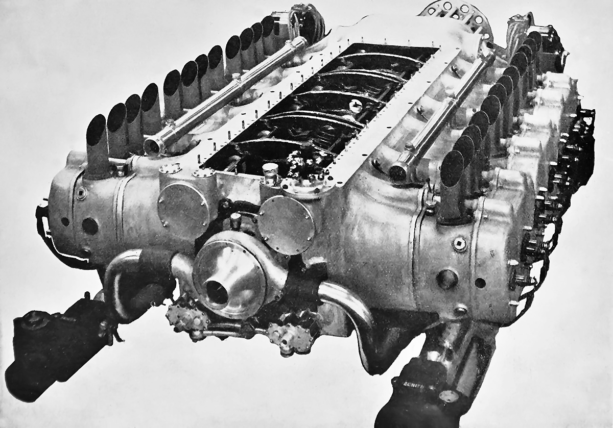
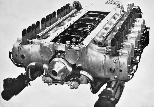
Rear view of the Caffort 12Aa engine much as it appeared at the 1926 Paris Salon de l’Aviation. The engine’s large top cover is removed to display the crankshaft and inside the crankcase. Note the pushrod tubes extending between the exhaust stacks and the crankshaft-driven water pump.
On 13 May 1921, Bertrand and Solant submitted a patent application in France to cover their engine design. While the French patent has not been found, other patents were taken out in Germany (373,157 / 412,196), the United States (1,634,866 / 1,673,484), Spain (81,435), Austria (97,016), Switzerland (103,293), and Britain (179,959).
Anciens Établissements Caffort Fréres (Caffort Brothers) in Paris produced parts for automobiles before World War I. During World War I, the company produced aircraft engines under license. In the early 1920s, Caffort built its own automobile chassis which found limited success. Powered by a two-cylinder, horizontally-opposed, air-cooled engine, the front-wheel drive machine was out of production by 1922. In 1923, the company decided to build a large aircraft engine. A few configurations were considered, but ultimately a 12-cylinder horizontally-opposed (180-degree V-12) engine of the Bertrand-Solant design was selected. This engine was known as the Caffort 12Aa, and its flat configuration would enable its installation submerged within the wing of larger aircraft. Most sources state that Caffort purchased a license for the Bertrand-Solant design, but it seems that at least Bertrand was involved with the engine’s construction.
The 12Aa had a large, one-piece, aluminum crankcase that was closed out by top and bottom covers and the propeller gear reduction. Cast integral with the crankcase were the cylinder blocks. Each block consisted of a pair of cylinders, and there were three blocks on each side of the engine. At the center of the crankcase was the three-piece crankshaft supported by four roller main bearings. Each crankshaft section had two throws and served four cylinders. The sections were united via tapered and keyed joints, and each section was clocked 120 degrees from the next. Attached to each hollow crankpin was a fork-and-blade tubular connecting rod that served one cylinder on each side of the engine. The cast pistons were made of an aluminum-silicon alloy.
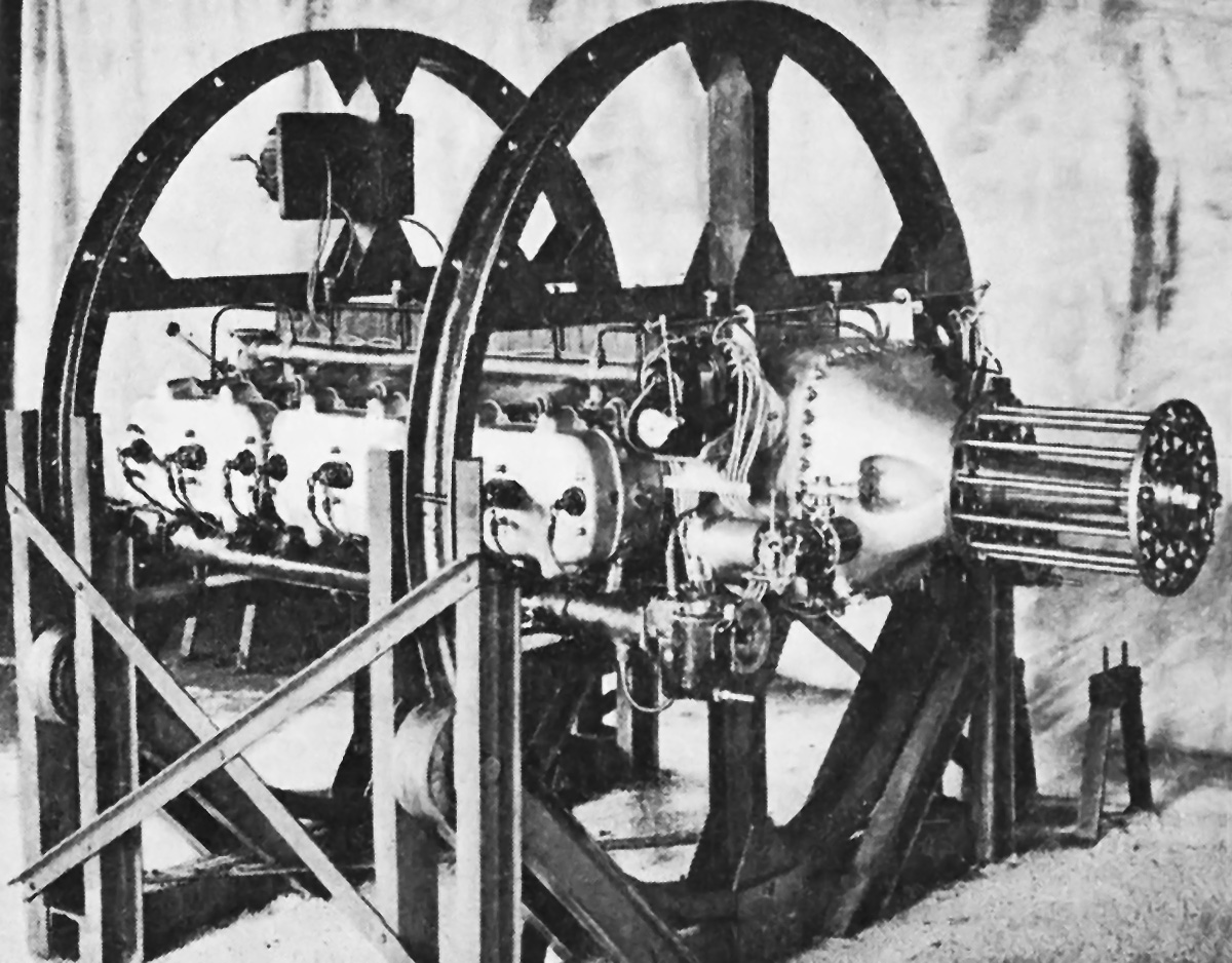
The 12Aa in a rotating assembly stand. Visible are the three cylinder blocks, each with a pair of cylinders. The long intake manifold can be seen under the cylinder bank. Note the four spark plugs in each cylinder pair valve cover.
Steel cylinder liners were inserted in the cylinder blocks, and an aluminum cylinder head sealed the pair of cylinders in each block. The cylinder’s compression ratio was 5.3 to 1. Each cylinder had two intake valves in its lower side and two exhaust valves in its upper side. Four camshafts were housed in the crankcase, with one at each corner, and the camshafts were driven from the rear of the crankshaft via spur gears. The camshafts acted on enclosed pushrods that ran along the upper and lower sides of their respective cylinders to actuate the valves via rocker arms. A cover concealed the valve gear atop each cylinder pair. A water pump driven from the rear of the crankshaft supplied coolant to the lower side of each cylinder bank via separate manifolds. The water circulated through the cylinder water jackets and was collected in a manifold that ran along the upper side of the cylinder bank. Each cylinder pair had a single coolant inlet and a single coolant outlet.
A tubular intake manifold under each bank of cylinders extended the length of the engine. A carburetor was mounted to the front and rear of each manifold, giving the engine a total of four carburetors. The air and fuel charge in each cylinder was ignited by two spark plugs in the cylinder head. The spark plugs were fired by two magnetos mounted at the front of the engine and just behind the gear reduction. The magnetos were driven from the crankshaft via a transverse shaft. Two fuel pumps driven by right-angle drives from another transverse shaft were mounted below the magnetos. The exhaust gases were expelled from the cylinders via individual stacks atop the engine.
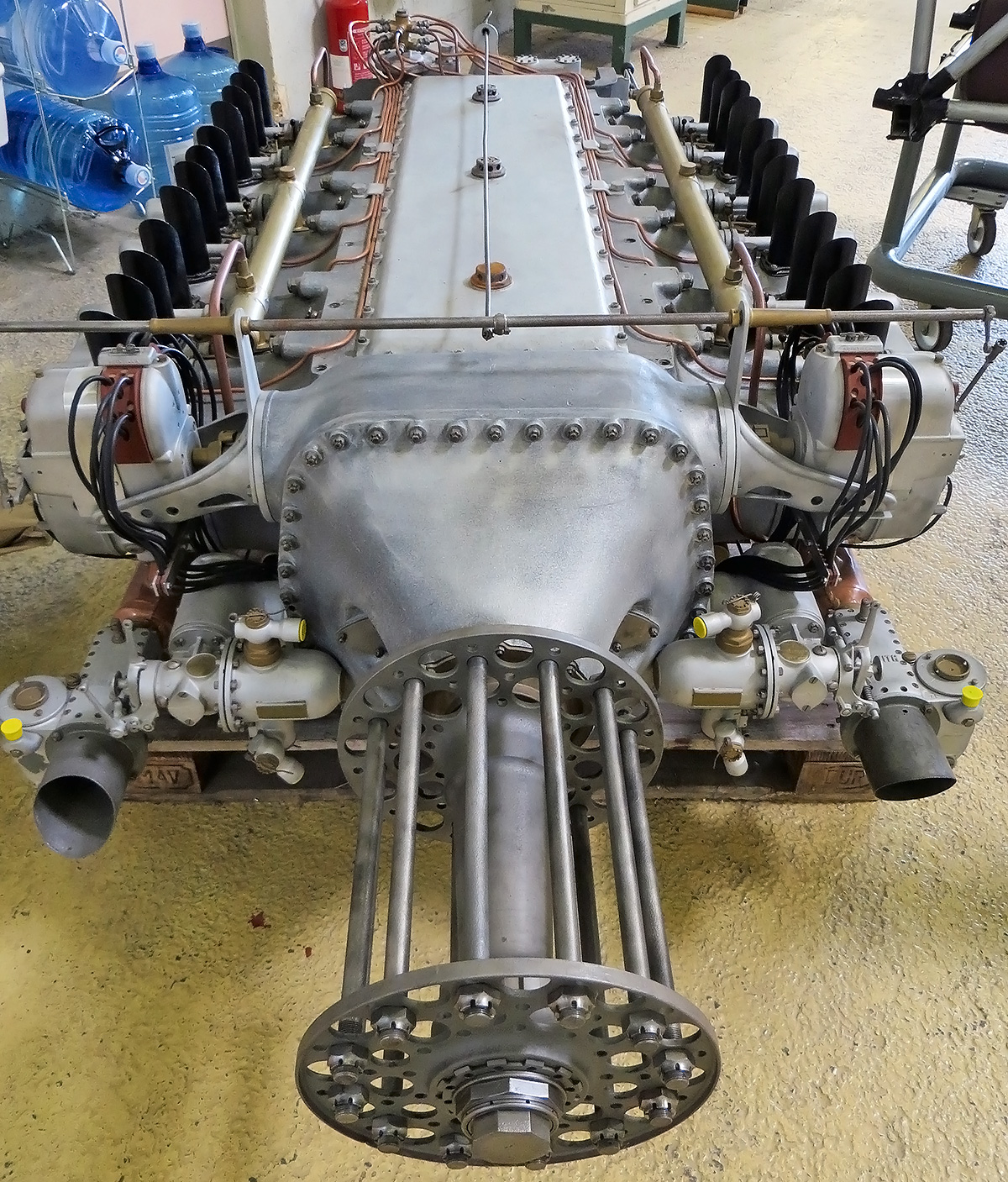
Image of the 12Aa in the Le Bourget Air & Space Museum providing a good top view of the engine, the upper crankcase cover, and the magnetos. Note the fuel pumps by the front carburetors. (Aerofossile2012 image)
The engine’s propeller shaft was coaxial to the crankshaft and turned at .53 engine speed. The propeller gear reduction was achieved by compound spur gears that ran on two layshafts—one mounted on each side of the crankshaft. A gear mounted to the crankshaft engaged teeth on the rear half of each compound spur gear. The front half of each compound spur gear engaged teeth on the propeller shaft. The engine’s configuration also enabled the removal of the compound reducing gears and the substitution of a direct drive propeller shaft. An air starter was mounted at the rear of the engine.
The Caffort 12 Aa had a 5.71 in (145 mm) bore and a 5.91 in (150 mm) stroke. The engine’s total displacement was 1,814 cu in (29.72 L). The 12Aa produced 550 hp (410 kW) at 2,000 rpm and 600 hp (447 kW) at 2,200 rpm. The engine had a length of 7 ft 3 in (2.20 m), a width of 4 ft 1 in (1.25 m), a height of 1 ft 10 in (.55 m), and a weight of 1,213 lb (550 kg).
Initially, Caffort planned to build six 12 Aa engines, but it appears that only one prototype was made. The engine was completed in the fall of 1926 and was first run in late October or early November. It was then displayed at the 1926 Paris Salon de l’Aviation (Air Show). The 12 Aa underwent testing in 1927 and recorded and output of 570 hp (425 kW) at 2,030 rpm. Either mechanical or financial issues (or both) were encountered, and development of the 12 Aa was not continued. The sole Caffort 12Aa was preserved and is held by the Le Bourget Air & Space Museum near Paris.
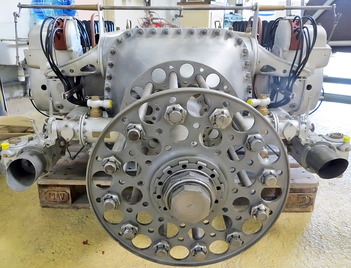
Note the attachment of the nose case to the 12Aa. The layshafts and spur reduction gears in the nose case could be removed and a new propeller shaft fitted to enable direct drive. (Aerofossile2012 image)
Sources:
– Jane’s All the World’s Aircraft 1928 by C. G. Grey (1928)
– Les Moteurs a Pistons Aeronautiques Francais Tome I by Alfred Bodemer and Robert Laugier (1987)
– “Les moteurs d’aviation exposés au 10ᵒ Salon,” L’Aéronautique Volume 9 Number 12 (January 1935)
– “The Paris Aero Show 1926,” Flight (9 December 1926)
– “Internal-Combustion Engine with Cylinders Arranged in Two Opposite Lines” US patent 1,634,866 by Jean Joseph Marie Bertrand and Louis Joseph Henry Solant (filed 20 April 1922)
– “Internal-Combustion Engine with Cylinders Arranged in Two Opposite Lines” US patent 1,673,484 by Jean Joseph Marie Bertrand and Louis Joseph Henry Solant (filed 30 November 1926)
