Category Archives: World War II

Fisher P-75A top

Fisher (General Motors) P-75 Eagle Fighter

By William Pearce

Donovan (Don) Reese Berlin had worked as the Chief Engineer for the Curtiss-Wright Corporation. He had designed the company’s successful P-36 Hawk and P-40 Warhawk fighters. Berlin also designed a number of unsuccessful fighters. He left Curtiss-Wright in December 1941 in frustration because he felt the company was not sufficiently supporting his efforts to develop a new fighter. At the request of the US government, Berlin was quickly hired by General Motors (GM) in January 1942 as the Director of Aircraft Development at the Fisher Body Division (Fisher).

Fisher XP-75 43-46950

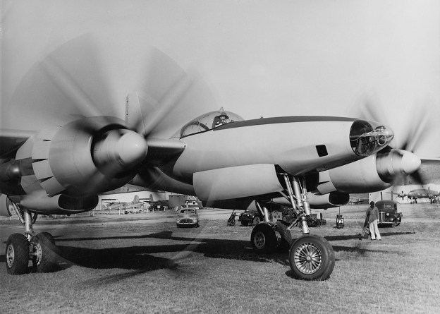
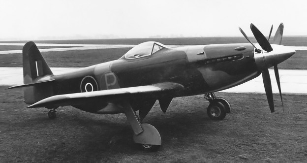
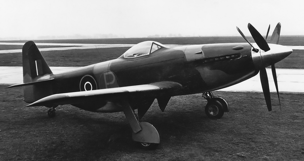
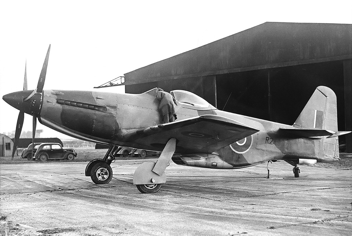
The Fisher P-75 Eagle was supposed to be quickly and inexpensively developed by utilizing many existing components. However, many resources were expended on the aircraft. The first XP-75 (43-46950) had a uniquely pointed rear canopy. It was also the only example that used a relatively unaltered Douglas A-24 empennage. Note the fixed tailwheel and the fairings that covered the machine gun barrels in the aircraft’s nose.

Fisher was already engaged by the government to build large assembles for the North American B-25 Mitchell bomber, and plans for the manufacture of other aircraft components were in the works. It made sense to have a prominent aeronautical engineer as part of Fisher’s staff. In March 1942, Fisher was tasked to build various components (engine cowlings, outer wing panels, ailerons, flaps, horizontal stabilizers, elevators, vertical stabilizers, rudders) of the Boeing B-29 Superfortress and 200 complete aircraft. A new plant in Cleveland, Ohio would be built to support this order. Beyond Fisher, a number of other GM divisions were involved in building aircraft and aircraft engines under license from other manufacturers. However, GM wanted to design and manufacture its own products to support the war effort. Berlin was a believer in applying automotive methods to produce aircraft, which was a good match for the automotive giant GM.

On 10 September 1942, GM, through Fisher, submitted a proposal to the Army Air Force (AAF) for a new interceptor fighter. The proposal was based on an AAF request from February 1942 for such an aircraft with exceptional performance. The aircraft from Fisher was designed by Berlin, powered by an Allison V-3420 24-cylinder engine, and constructed mainly of components from other aircraft. The aircraft offered impressive performance with a top speed of 440 mph (708 km/h) at 20,000 ft (6,096 m), a 5,600 fpm (28.5 m/s) initial climb rate, a service ceiling of 38,000 ft (11,582 m), and a range of 2,240 miles (3,605 km) with only internal fuel. All of this came with a promise to deliver the first aircraft within six months of the contract being issued.

Fisher XP-75 line

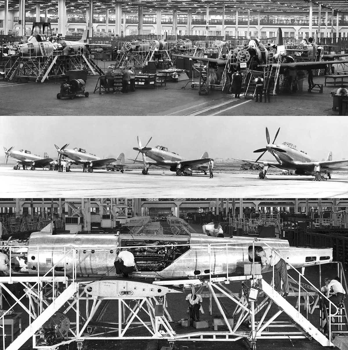
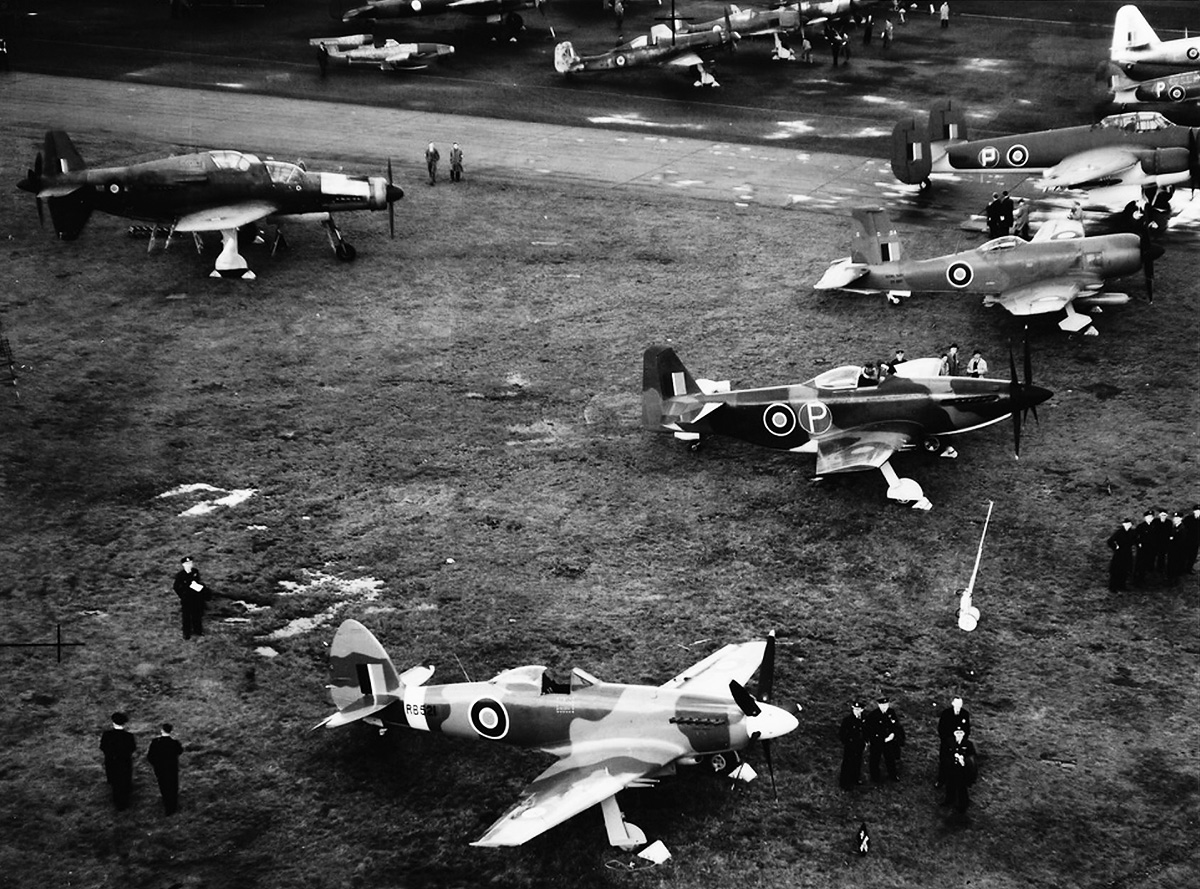
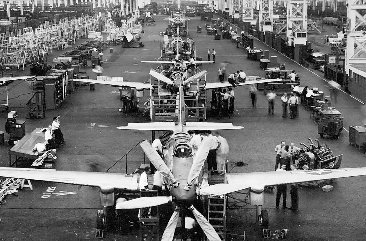
The top image shows at least five XP-75A aircraft under construction. The middle image, from right to left, shows the first two XP-75 aircraft (43-46950 and 43-46951) and the first two XP-75A aircraft (44-32161 and 44-32162). The second XP-75 (second from the right) has the wide H-blade propellers installed, while the other aircraft have the narrow A-blade propellers. The bottom image is a P-75A under construction. Note the V-3420 engine. (Veselenak Photograph Collection / National Museum of the US Air Force images)

Back in February 1941, the Army Air Corps (name changed to AAF in June 1941) had considered the Allison V-3420 as a possible replacement for the Wright R-3350 engine intended for the B-29. The Allison Engineering Company was a division of GM, and at the time, development of the V-3420 was focused on creating the basic engine and not much more. However, the priority of the V-3420 program was scaled-back after the Japanese attacked Pearl Harbor on 7 December 1941.

GM had been searching for an application for its Allison V-3420 engine, and the AAF had tried to entice other manufactures to incorporate the engine in a fighter design. Fisher’s fighter project offered a solution for both entities. The AAF was sufficiently impressed with Fisher’s proposal, and they approved the construction of two prototypes (serials 43-46950 and 43-46951) on 10 October 1942. The aircraft was given the designation P-75 Eagle, with the prototypes labeled XP-75. Some believe the pursuit number “75” was issued specifically at Berlin’s request, as his “Model 75” at Curtiss-Wright became the successful P-36 and led to the P-40. Although there were some reservations with the aircraft’s design, it was believed that a team working under the experienced Berlin would resolve any issues encountered along the way.

Fisher XP-75A long-range side

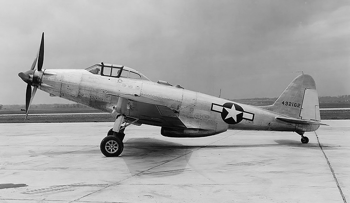
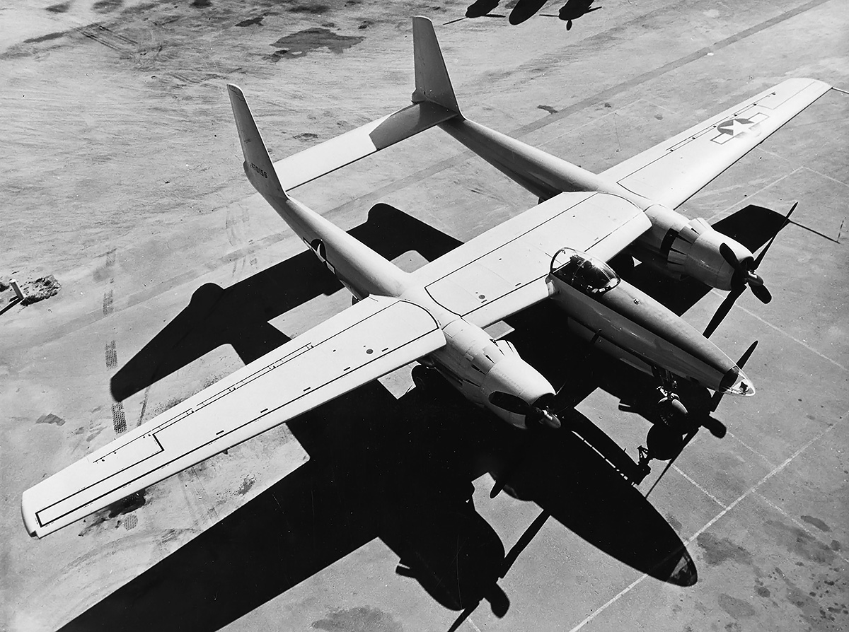
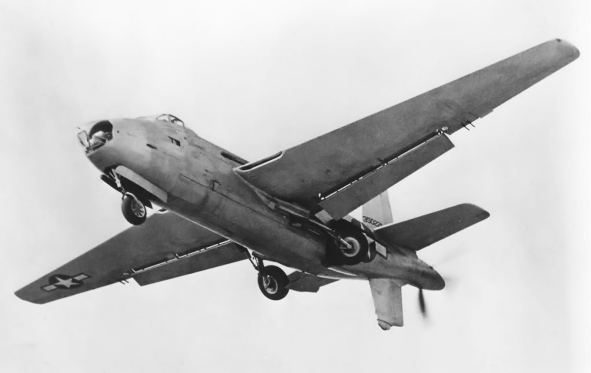
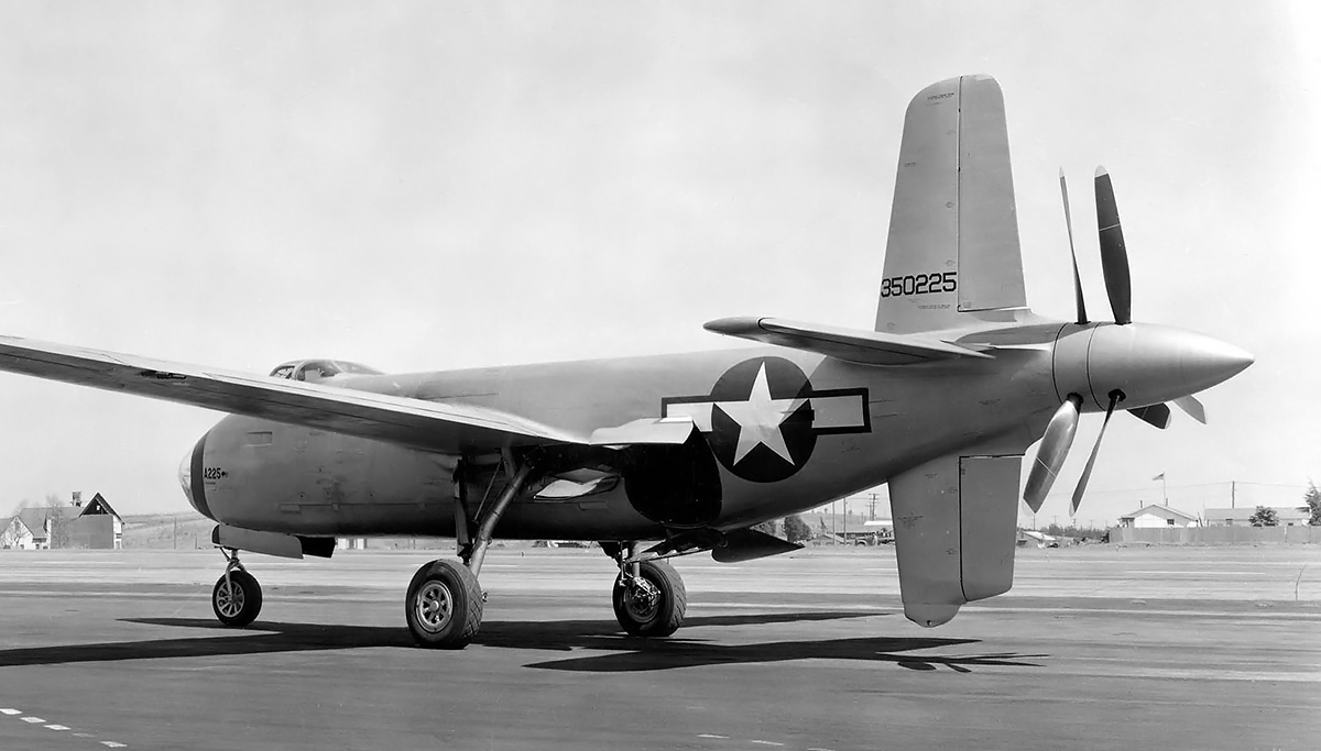
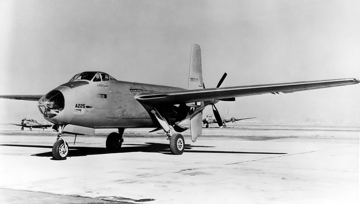
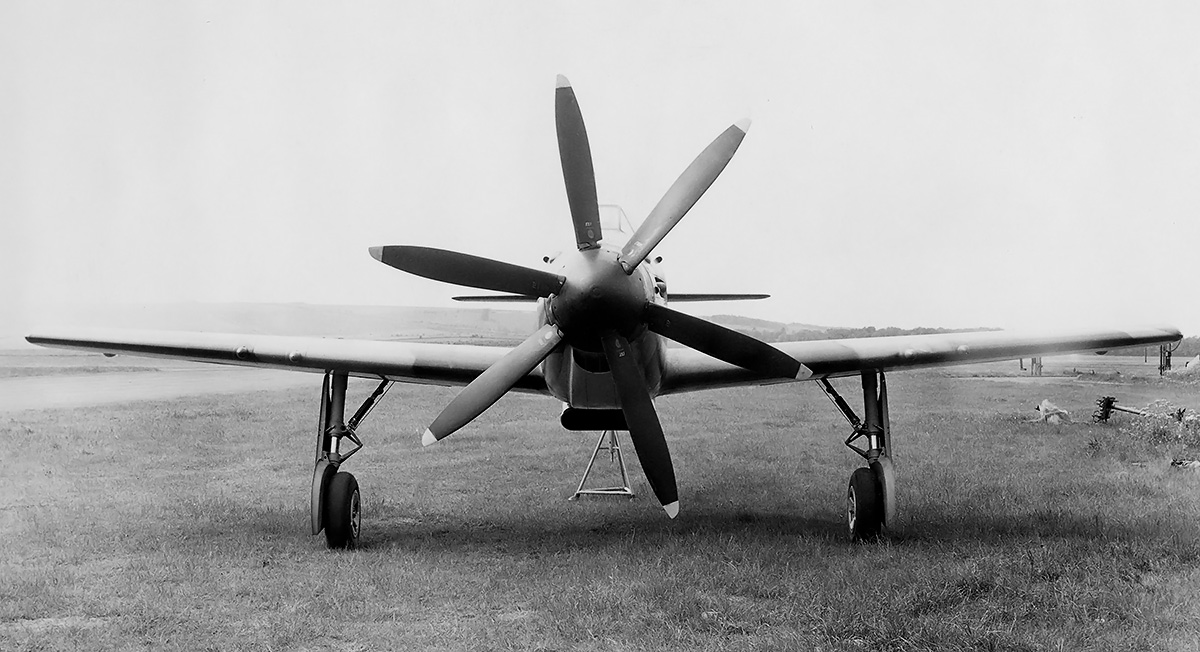
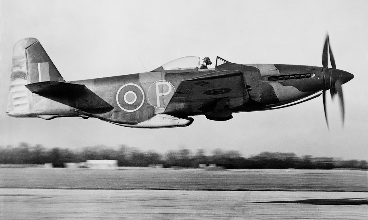
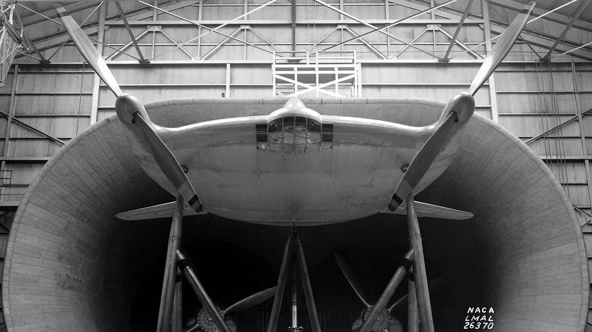
Aircraft 44-32162 was the fourth of the XP-75-series and the second XP-75A with additional wing fuel tanks. Note the revised canopy and tail compared to the first prototype. The aircraft has narrow A-blade propellers, and the 10-gun armament appears to be installed.

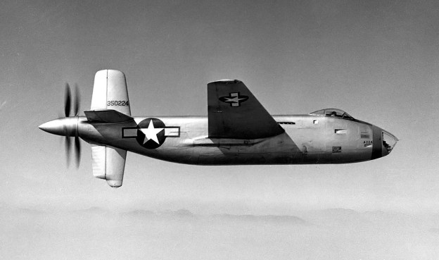
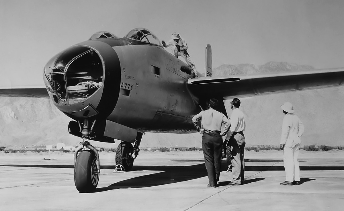
The XP-75 was of all metal construction with fabric-covered control surfaces. The cockpit was positioned near the front of the aircraft and provided the pilot with good forward and downward visibility. The pilot was protected by 177 lb (80 kg) of armor. The cockpit canopy consisted of front and side panels from a P-40. The aircraft’s empennage, with a fixed tailwheel, was from a Douglas A-24 Banshee (AAF version of the Navy SBD Dauntless). Initially, North American P-51 Mustang outer wing panels would attach to the inverted gull wing center section that was integral with the fuselage. However, the P-51 wings were soon replaced by wings from a P-40 attached to a normal center section. The main landing gear was from a Vought F4U Corsair, and it had a wide track of nearly 20 ft (6.10 m). Four .50-cal machine guns were mounted in the aircraft’s nose and supplied with 300 rpg. Each wing carried three additional .50-cal guns with 235 rpg. Under each wing, inside of the main gear, was a hardpoint for mounting up to 500 lb (227 kg) of ordinance or a 110-US gal (416-L) drop tank.

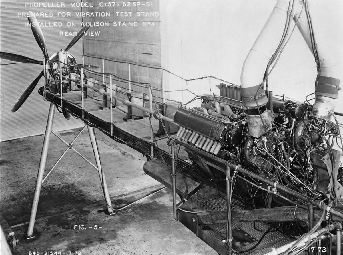
The 2,600 hp (1,939 kW) Allison V-3420-19 engine with a two-stage supercharger was positioned in the fuselage behind the pilot. Each of the engine’s four cylinder banks had an air-cooled exhaust manifold with two exhaust stacks protruding out of the fuselage. Two extension shafts passed under the cockpit and connected the engine to the remote gear reduction box for the Aeroproducts six-blade contra-rotating propeller. Two different types of propellers were used. Initially, a 13 ft (3.96 m) diameter, narrow, A-blade design was used. Many sources state that this propeller was used on the first 12 aircraft. However, some of these aircraft flew with the second design, a 12 ft 7 in (3.84 m) diameter, wide, H-blade. The gear reduction turned the propeller at .407 crankshaft speed.

Fisher XP-75A 44-32161 crash

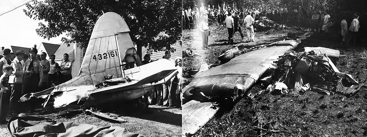
The empennage (left) and inverted wings and fuselage (right) of XP-75A 44-32161 after its crash on 5 August 1944. An engine explosion and inflight fire led to the empennage separating from the rest of the aircraft. Russell Weeks, the pilot, was able to bail out of the stricken aircraft. (Veselenak Photograph Collection / National Museum of the US Air Force images)

A two-section scoop was located under the fuselage, just behind the wings. The left section held an oil radiator, and coolant radiators were positioned in both the left and right sections. The aircraft’s oil capacity and coolant capacity were 28.5 US gal (108 L) and 31.5 US gal (119 L) respectively. A 485-US gal (1,836-L) fuel tank was positioned in the fuselage between the cockpit and engine. The tank was made of two sections with the extension shafts passing between the sections.

An XP-75 mockup was inspected by the AAF on 8 March 1943. On 6 July, six additional prototypes (serials 44-32161 to 44-32166) were ordered with some design modifications, including changes to the cockpit canopy, the use of a 2,885 hp (2,151 kW) V-3240-23 engine, and additional fuel tanks in each wing with a capacity of 101 US gal (382 L). The extra fuel enabled the P-75 to cover the long-range escort role, something that the AAF was desperately seeking. The long-range fighter prototypes are often referred to as XP-75As, although this does not appear to be an official designation.

Fisher XP-75A assembly

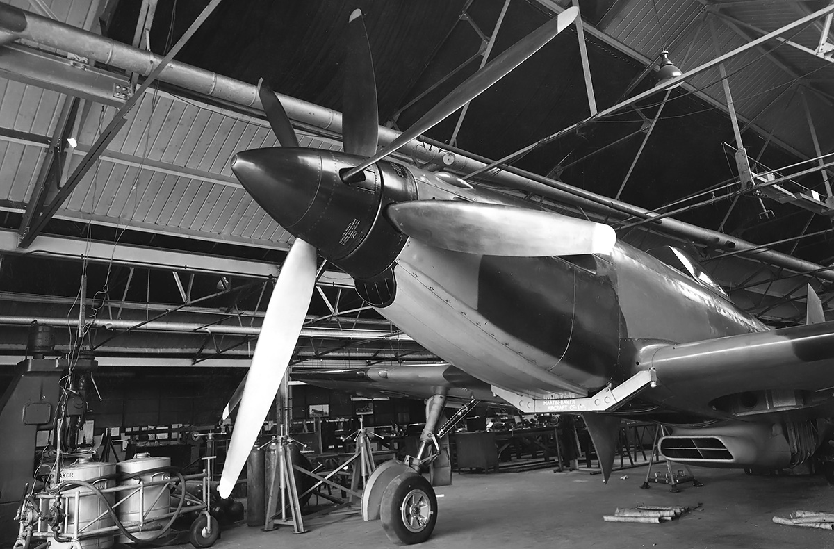
This image shows either 44-32165 or 44-32166 being completed in the Cleveland plant. These two aircraft, the last of the XP-75As, had a bubble canopy, retractable tailwheel, and a new, tall rudder and vertical stabilizer. Note the P-40-style rounded wings. (Veselenak Photograph Collection / National Museum of the US Air Force image)

Since the need for interceptors had faded, many in the AAF were optimistic that the long-range P-75 would be able to escort bombers all the way into Germany and that the aircraft would be able to outperform all German fighters for the foreseeable future. The P-75 also served as insurance if the P-51 and Republic P-47 Thunderbolt could not be developed into long-range escort fighters.

On 8 July 1943, a letter of intent was issued for the purchase of 2,500 P-75A aircraft (serials 44-44549 to 44-47048), but a stipulation allowed for the cancellation of production if the aircraft failed to meet its guaranteed performance. A definitive contract for all of the XP-75 work was signed on 1 October 1943 and stipulated that the first XP-75 prototype would fly by 30 September 1943, and the first long-range XP-75A prototype would fly by December 1943. The first production aircraft was expected in May 1944, and production was forecasted to eventually hit 250 aircraft per month. The production costs for the 2,500 P-75A aircraft was estimated at $325 million.

Fisher XP-75A 44-32165 side

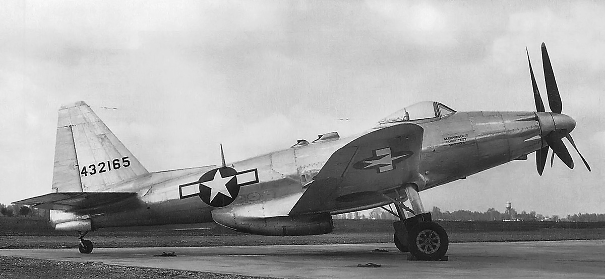
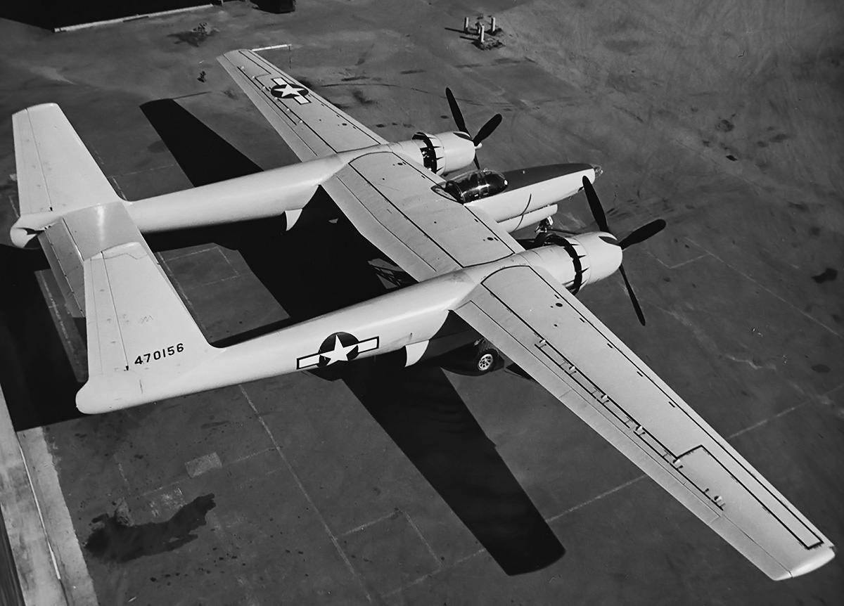
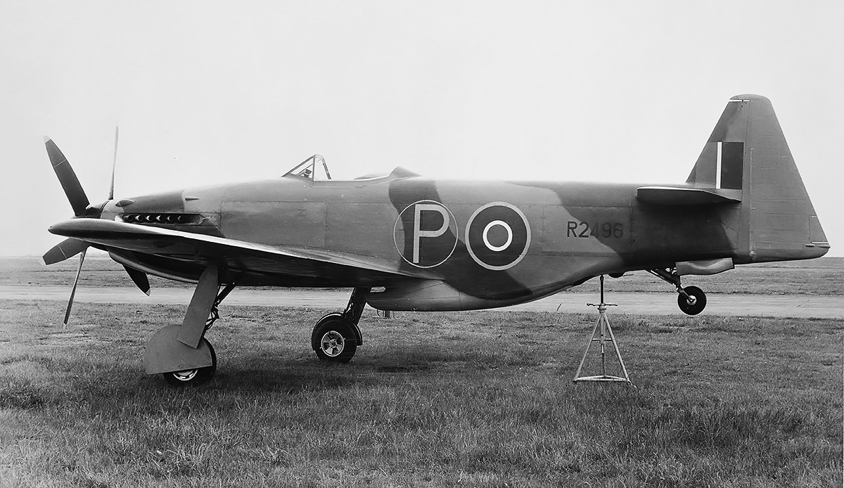
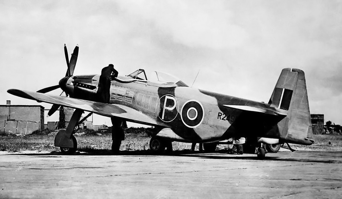
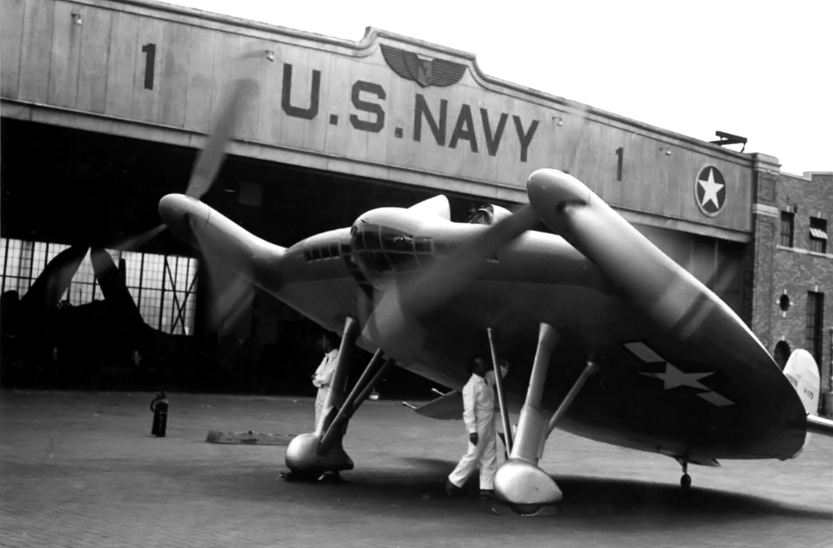
XP-75A 44-32165 with the new (and final) large, angular tail and horizontal stabilizer. However, the aircraft retained the rounded wings. Note the ventral strake behind the belly scoop, and the wide H-blade propellers. The same modifications were applied to 44-32166. The stenciling under the canopy says “Aeroproducts Flight Test Ship No 4.”

The Fisher XP-75A had a wingspan of 49 ft 1 in (14.96 m), a length of 41 ft 4 in (12.60 m), and a height of 14 ft 11 in (4.55 m). The aircraft’s performance estimates were revised to a top speed of 434 mph (698 km/h) at 20,000 ft (6,096 m) and 389 mph (626 km/h) at sea level. Its initial rate of climb was 4,200 fpm (21.3 m/s), with 20,000 ft (6,096 m) being reached in 5.5 minutes, and a service ceiling of 39,000 ft (11,887 m). The aircraft had an empty weight of 11,441 lb (5,190 kg) and a fully loaded weight of 18,665 lb (8,466 kg). With the fuselage tank, a total of 203 US gal (768 L) of fuel in the wings, and a 110-US gal (416-L) drop tank under each wing, the XP-75A had a maximum range of 3,850 miles (6,196 km).

The AAF gave the XP-75 priority over most of Fisher’s other work, particularly that of constructing 200 B-29 bombers. Construction of the first two prototypes was started at Fisher’s plant in Detroit, Michigan. The other six XP-75 aircraft were built at the new plant in Cleveland, Ohio, which opened in 1943. Production of the aircraft would occur at the Cleveland plant.

Fisher P-75A assembly line

The production line with P-75A numbers two through four (44-44550 through 44-44553) under construction. While the aircraft have square wingtips, at least the first one still has the rounded horizontal stabilizer. Note the V-3420 engine by the first aircraft. The wing of an XP-75A is visible on the far right.

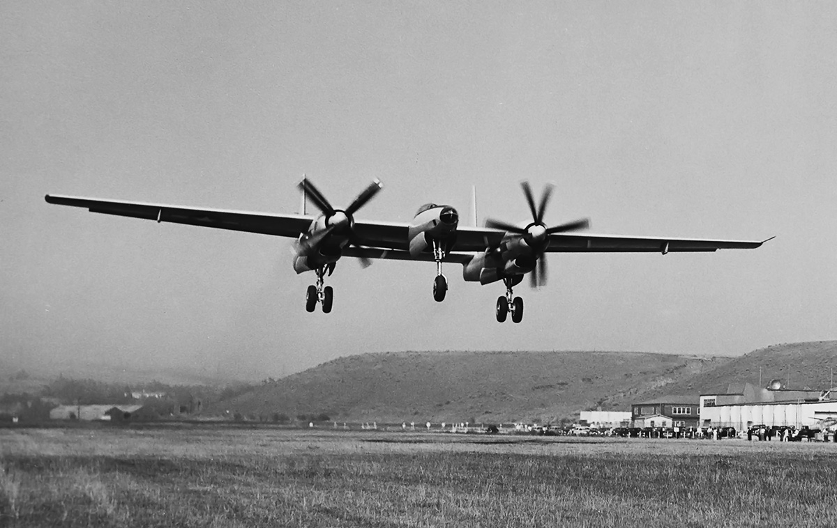
Flown by Russell Thaw, the XP-75 prototype (43-46950) made its first flight on 17 November 1943, and it was the first aircraft to fly with the V-3420 engine. Almost immediately the aircraft ran into issues: the center of gravity was off; the ailerons were heavy; the controls were sluggish; the aircraft exhibited poor spin characteristics; and the V-3420 engine was down on power and overheating. The trouble is not very surprising considering the aircraft consisted of parts from other aircraft and was powered by an experimental engine installed in an unconventional manner. The V-3420’s firing order was revised for smoother operation. Modifications to the second prototype (43-46951) included changes to the ailerons and a new rear canopy. The size of the rudder was decreased, but the surface area of the vertical stabilizer was increased by extending its leading edge. The second XP-75 prototype was completed in December 1943 and made its first flight on 27 January 1944.

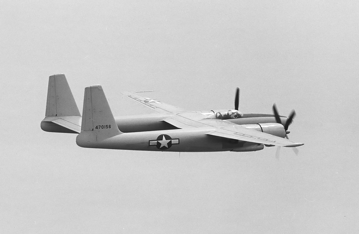
The first of the six XP-75A long-range aircraft (44-32161) flew on 24 January 1944. The last two of these aircraft, 44-32165 and 44-32166, were finished with a bubble canopy and a new empennage. The new empennage had a retractable tailwheel and a taller vertical stabilizer and rudder. Lateral control was still an issue, and these two aircraft were later modified with larger and more angular vertical and horizonal stabilizers. These changes were also incorporated into most of the P-75A production aircraft.

Fisher P-75A 44-44549

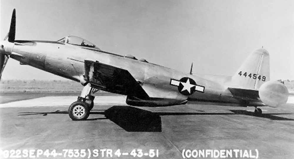
The first production P-75A (44-44549) with its square wingtips and original rounded tail. Note the ventral strake and the fins attached to the horizontal stabilizer. It is not known when the picture was taken (possibly 22 September 1944), but the aircraft and pilot were lost on 10 October 1944.

The third long-range XP-75A aircraft (44-32163) crashed on 8 April 1944, killing the pilot, Hamilton Wagner. The crashed may have been caused by the pilot performing unauthorized aerobatics. On 7 June 1944, the AAF issued the contract for 2,500 P-75A aircraft. Official trials were conducted in June 1944 and indicated that the XP-75A aircraft was well short of its expected performance. A top speed of only 418 mph (673 km/h) was achieved at 21,600 ft (6,584 m), and initial climb rate was only 2,990 fpm (15.2 m/s). However, the engine was reportedly not producing its rated output. On 5 August 1944, XP-75A 44-32161 was lost after an inflight explosion, which separated the empennage from the rest of the aircraft. The pilot, Russell Weeks, successfully bailed out.

In addition to other changes made throughout flight testing of the prototypes, the P-75As incorporated extended square wingtips with enlarged ailerons, the controls were boosted to eliminate the heavy stick forces, and a ventral strake was added that extended between the scoop exit doors and the tailwheel. The P-75A had a wingspan of 49 ft 4 in (15.04 m), a length of 41 ft 5 in (12.62 m), and a height of 15 ft 6 in (4.72 m). The aircraft’s performance estimates were revised down, with a top speed of 404 mph (650 km/h) at 22,000 ft (6,706 m). Its initial rate of climb dropped to 3,450 fpm (17.5 m/s), and the service ceiling decreased to 36,400 ft (11,095 m). The aircraft had an empty weight of 11,255 lb (5,105 kg) and a fully loaded weight of 19,420 lb (8,809 kg).

Fisher P-75A runup

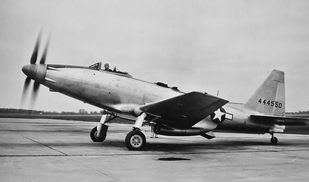
P-75A 44-44550 with the new (and final) square tail and horizontal stabilizer. Note the two-section belly scoop and the F4U main landing gear.

The first two P-75As (44-44549 and 44-44550) were not originally finished with the latest (angular) empennage. Rather, they used the tall, round version that was originally fitted to the last two XP-75A prototypes. A dorsal fillet was later added to the vertical stabilizer. The first Fisher P-75A (44-44549) took flight on 15 September 1944, with the second aircraft (44-44550) following close behind. Aircraft 44-44550 was later altered with the enlarged, square-tipped vertical and horizontal stabilizers, but it is not clear if 44-44549 was also changed. At some point (possibly late September 1944), aircraft 44-44549 had stabilizing fins added to the ends of its horizontal stabilizer. Both aircraft were sent to Eglin Field, Florida for trials. On 10 October 1944, aircraft 44-44549 was lost with its pilot, Harry Bolster. The crash was caused by the propellers becoming fouled by either a nose-gun tube failure or by part of the spinner breaking free. The damaged propellers quickly destroyed the gear reduction, and once depleted of oil, the propeller blades went into a flat pitch. Bolster attempted a forced landing but was not successful.

By the time of the last crash, the AAF had realized it would not need the P-75A aircraft. The P-51B/D and P-47D/N had proven that they were up to the task of being long-range escort fighters, and the war’s end was in sight. The P-75A was larger, heavier, slower, and sluggish compared to fighters already in service. The production contract for the 2,500 P-75As was cancelled on 6 October 1944, and further experimental work was stopped on 8 November. Five P-75A aircraft were completed, with an additional, nearly-complete airframe delivered for spare parts. Construction of approximately 20 other P-75A production aircraft had started, with some assemblies being completed.

Fisher P-75A top

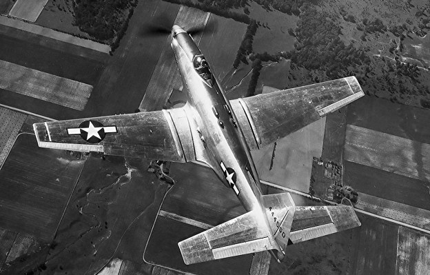
A top view of 44-44550 provides a good illustration of the square wingtips and horizontal stabilizer. The wings were only slightly extended, but the area of the ailerons was increased by a good amount. The square extensions to the horizontal stabilizer increased its area significantly. Note that the machine gun armament is installed.

P-75A 44-44550 was later transferred to Moffett Field, California where it underwent tests on the contra-rotating propellers. The aircraft was scrapped after the tests. In an attempt to produce more power, a new intercooler was installed in 44-44551, and the aircraft was lent to Allison on 28 June 1945. Later, a 3,150 hp V-3420 was installed. Aircraft 44-44552 and 44-44553 were sent to Patterson Field, Ohio and stored for further V-3420 development work. None of the aircraft were extensively flown. The last completed P-75A, 44-44553, was preserved and is currently on display in the National Museum of the US Air Force in Dayton, Ohio. The aircraft went through an extensive restoration in 2008. All other P-75 aircraft were eventually scrapped.

The eight prototype aircraft had cost $9.37 million, and the manufacturing contract, including the six production aircraft, construction of the Cleveland plant, and tooling for production, had cost $40.75 million. This gave a total expenditure of $50.21 million for the 14 P-75 aircraft. In the end, the expeditious and cost-saving measure of combining existing components led to delays and additional costs beyond that of a new design. It turned out that the existing assemblies needed to be redesigned to work together, essentially making the P-75A a new aircraft with new components.

Fisher P-75A side

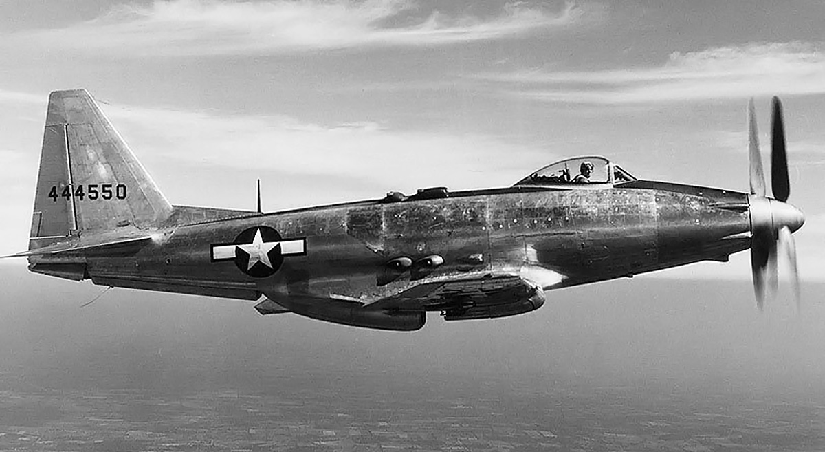
The pilot under 44-44550’s bubble canopy helps illustrate the aircraft’s rather large size. The P-75’s sluggish handling and lateral instability did not endear the aircraft to test pilots. Note the nearly-wide-open rear shutter of the belly scoop.

An often-cited story states that then Col. Mark E. Bradley, Chief of Aircraft Projects at Wright Field, was so dissatisfied with the XP-75 after making a test flight, that he requested North American add a large fuel tank in the fuselage of the P-51 Mustang. This act led to the ultimate demise of the XP-75 and the ultimate success of the P-51. However, that sequence of events is not entirely accurate.

Bradley initiated North American’s development of the P-51 fuselage tank in July 1943, after evaluating the XP-75’s design. Experiments with the P-51’s 85-gallon (322-L) fuselage tank were successfully conducted in August 1943. In early September 1943, kits to add the tank to existing P-51s were ordered, and about 250 kits arrived in England in November. At the same time, the fuselage tank was incorporated into the P-51 production line. These events preceded the XP-75 prototype’s first flight on 17 November 1943. Bradley’s later flight in the XP-75 solidified his view that the P-51 with the fuselage tank was the best and quickest option for a long-range escort, and that the XP-75, regardless of its progression through development, would not be superior in that role.

Fisher P-75A USAFM

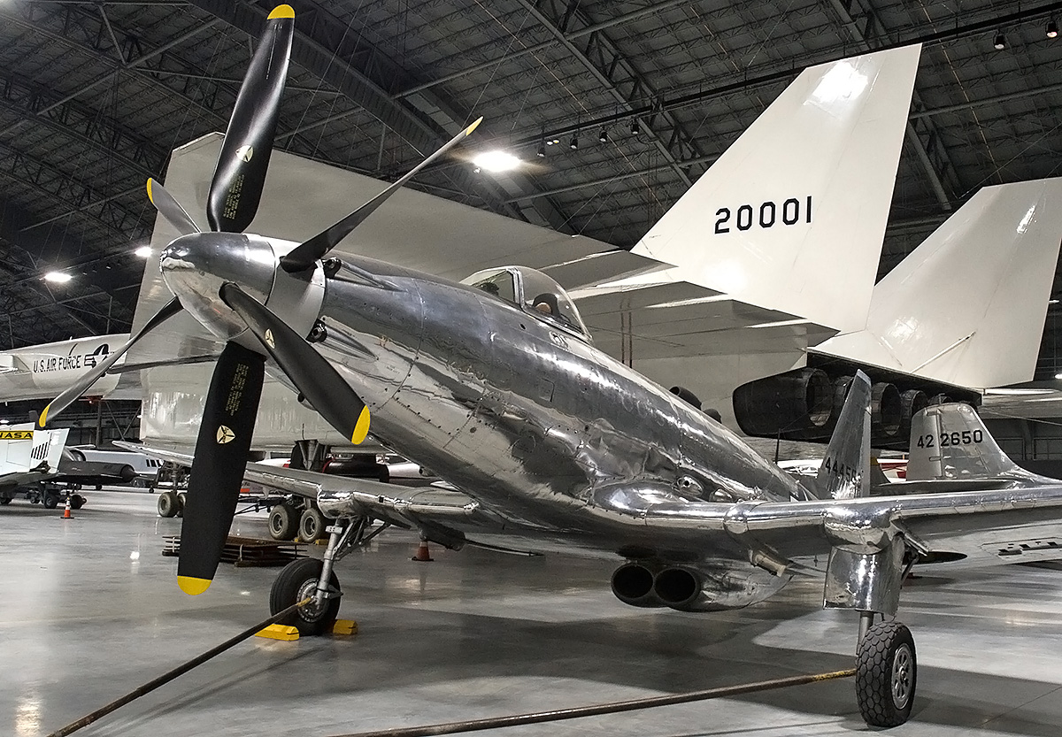
Fisher P-75A 44-44553 has been preserved and is on display in the National Museum of the US Air Force. (US Air Force image)

Sources:
U.S. Experimental & Prototype Aircraft Projects Fighters 1939–1945 by Bill Norton (2008)
Vees For Victory!: The Story of the Allison V-1710 Aircraft Engine 1929-1948 by Dan Whitney (1998)
P-75 Series Airplanes Advance Descriptive Data (20 May 1944)
P-51 Mustang: Development of the Long-Range Escort Fighter by Paul A. Ludwig (2003)
Development of the Long-Range Escort Fighter by USAF Historical Division (1955)
– “Le Fisher XP-75 Eagle” by Alain Pelletier, Le Fana de l’Aviation (August 1996)
– “A Detroit Dream of Mass-Produced Fighter Aircraft: The XP-75 Fiasco” by I. B. Holley, Jr. Technology and Culture Vol. 28, No. 3 (July 1987)
http://usautoindustryworldwartwo.com/Fisher%20Body/fisherbodyaircraft.htm
http://www.alexstoll.com/AircraftOfTheMonth/3-00.html
https://en.wikipedia.org/wiki/List_of_accidents_and_incidents_involving_military_aircraft_(1943%E2%80%931944)

arsenal vg 33 rear

Arsenal VG 30-Series (VG 33) Fighter Aircraft

By William Pearce

In the early 1930s, some in France felt that French aviation was falling behind the rest of the world. French aircraft manufacturers were not experimenting much on their own, and government-funded conventional aircraft projects were not pushing the technical boundaries of aeronautics. On 2 July 1934, Pierre Renaudel proposed creating a state research institution to study and develop modern aircraft for the French military. The Arsenal du matériel aérien (Arsenal aerial equipment) was formed later that year with engineer Michel Vernisse as its director. When the French aviation industry was nationalized in 1936, the organization was renamed Arsenal de l’aéronautique (Arsenal aeronautics) and took over the Bréguet works at Villacoublay, near Paris, France.

arsenal vg 30

The mockup of the Arsenal VG 30 as displayed at the 1936 Salon d’Aviation in Paris. Note the location of the radiator housing. Otherwise, the aircraft was very similar to subsequent VG 30-series fighters.

One of Arsenal’s first designs was the tandem-engine VG 10 fighter. Designed by Michel Vernisse and Jean Galtier, the initials of their last names formed the ‘VG’ of the aircraft’s designation. The VG 10 was never built and was redesigned and redesignated as the VG 20, which was also never built. However, the design was reworked again and eventually emerged as the Arsenal VB 10, first flown in 1945.

In 1936, the Ministère de l’Air (French Air Ministry) was interested in the concept of a light-fighter built from non-strategic materials. As a result, Arsenal designed the VG 30, a single-seat fighter constructed mostly of wood. The aircraft had a conventional taildragger layout with a low wing and featured retractable main undercarriage. At the rear of the aircraft was a non-retractable tailskid. Originally, the VG 30 was to be powered by the Potez 12 Dc: a 610 hp (455 kW), air-cooled, horizontal, 12-cylinder engine. However, delays with the 12 Dc resulted in a switch to the Hispano-Suiza 12Xcrs: a 690hp (515 kW), liquid-cooled, V-12 engine.

The wood used in the VG 30’s construction was primarily spruce, and the aircraft’s wooden frame was covered with molded sprue plywood to form the aircraft’s stressed-skin. The skin was then covered with canvas and varnished. The wings consisted of two spars and incorporated hydraulically operated flaps. The fuselage was mounted atop the wings, which were made as a single structure. The cockpit was positioned above the wing’s trailing edge and featured a rearward-sliding canopy. The engine’s cowling was made of aluminum, and to cool the engine, a radiator was housed in a duct positioned under the fuselage between the wings. Proposed armament consisted of a 20 mm cannon firing through the hub of the three-blade propeller and four 7.5 mm machine guns, with two housed in each wing. The cannon had 60 rounds of ammunition, and the wing guns each had 500 rounds.

arsenal vg 33 two

The VG 33 prototype sits complete with main gear doors on a muddy airfield. Many of the completed VG 33s, like the second aircraft in the image, were finished without gear doors.

A mockup of the VG 30 was displayed in November 1936 at the Salon d’Aviation in Paris. The Air Ministry found the mockup sufficiently impressive to issue specification A.23, requesting proposals for a light-fighter. A prototype of the Arsenal VG 30 was ordered in early 1937, and construction of the aircraft commenced in June. Some delays were encountered, and the VG 30 was first flown on 6 October (some sources state 1 October) 1938. The pilot for the flight was Modeste Vonner, and the aircraft took off from Villacoublay. Official tests were carried out from 24 March to 17 July 1939, during which the VG 30 reportedly reached 500 mph (805 km/h) in a dive. Overall, the tests revealed that the VG 30 had very good performance and was faster than the more-powerful Morane-Saulnier MS 406, France’s premier fighter just entering service.

The VG 30 had a wingspan of 35 ft 5 in (10.80 m), a length of 27 ft 7 in (8.40 m), and a height of 10 ft 10 in (3.31 m). The aircraft’s wing area was 150.69 sq ft (14.00 sq m). It had a top speed of 301 mph (485 km/h) at 16,240 (4,950 m) and climbed to 16,404 ft (5,000 m) in 7 minutes and 15 seconds. Despite the aircraft’s performance, VG 30 production was passed up in favor of more advanced models, and only the prototype was built.

The Arsenal VG 31 was a development of the VG 30 intended to enhance the aircraft’s speed. An 860 hp (641 kW) Hispano-Suiza 12Y-31 replaced the 690 hp (515 kW) engine; the radiator was relocated further back; two of the wing guns were removed; and a smaller wing was designed, resulting in 19.9–21.2 sq ft (1.85–2.0 sq m) less wing area. Wind tunnel tests indicated the aircraft would have reduced stability, reduced maneuverability, and an increased landing speed. The small gain in top speed was not worth all of the drawbacks. The VG 31 was never completed. The wings were used for static testing, and the fuselage was used on the third VG 33 aircraft, which became the VG 34.

arsenal vg 33 rear

A completed VG 33 without gear doors seen at Toulouse-Blagnac airport in June 1940. Note the radiator housing under the fuselage.

The Arsenal VG 32 was an attempt to secure a second source of power for the VG 30 aircraft. A 1,040 hp (776 kW) Allison V-1710-C15 (-33) replaced the Hispano-Suiza engine, requiring the fuselage to be lengthened by 16.5 in (.42 m) to 28 ft 11 in (8.82 m). The wings were modified to accommodate one 20 mm cannon and one 7.5 mm machine gun. Because of delays with acquiring the V-1710 engine, the VG 32 project followed after the VG 33. The fifth VG 33 airframe formed the basis for the VG 32, and a desperate France ordered 400 copies of the aircraft in 1940. However, the Germans arrived before the V-1710 engine, and the VG 32 was never completed. The aircraft was captured at Villacoublay in June 1940.

The Arsenal VG 33 was an enhancement to the basic VG 30 aircraft. The VG 33 used the 860 hp (641 kW) Hispano-Suiza 12Y-31 from the VG 31 but retained the larger wing of the VG 30. The engine turned a 12 ft 4 in (3.75 m) diameter three-blade, adjustable-pitch, metal propeller. An oil cooler was incorporated into the engine cowling just below the spinner, and a scoop for engine induction was located on the bottom of the cowling. The aircraft’s fuselage was lengthened slightly to 28 ft .5 in (8.55 m), and its height was 11 ft (3.35 m). The VG 33 prototype made its first flight on 25 April 1939 from Villacoublay. Official trials spanned from August 1939 to March 1940. The VG 33 was stable, maneuverable, easy to fly, and possessed good control harmony. The aircraft’s maneuverability and speed were superior to that of the more-powerful, all-metal Dewoitine D.520, France’s newest fighter.

arsenal vg 33 front captured

A VG 33 aircraft captured by the Germans and being tested at Rechlin, Germany. The captured aircraft carried the designation 3+5. The inlets for the oil cooler can bee seen just under the spinner. Under the cowling is the engine’s intake. Note the machine guns mounted in the wings.

The VG 33 had a maximum speed of 347 mph (558 km/h) at 17,060 ft (5,200 m) and a ceiling of 36,089 ft (11,000 m). The aircraft weighed 4,519 lb (2,050 kg) empty and 6,063 lb (2,750 kg) fully loaded. Its range was 746 miles (1,200 km) with 106 gallons (400 L) of internal fuel. Two fixed 26-gallon (100 L) external tanks could be attached under the wings to extend the aircraft’s range to 1,118 miles (1,800 km).

Before the flight trials were over, the Air Ministry ordered at least 200 VG 33s in September 1939. Another purchase request was submitted a short time later placing a total of approximately 720 VG 33 aircraft on order. The first deliveries were scheduled for January 1940, and the first fighter group equipped with VG 33 aircraft was to be operational in April 1940. The bulk of the orders went to SNCAN (Société nationale des constructions aéronautiques du Nord or National Society of Aeronautical Constructions North) at Sartrouville, with Michelin at Clermont-Ferrand expected to start production later.

Ironically, delays with acquiring enough non-strategic spruce resulted in the first production VG 33 aircraft not making its first flight until 21 April 1940. Production numbers for the VG 33 vary by source. By the time France surrendered to Germany on 22 June 1940, only about seven aircraft had been delivered to the Armée de l’Air (French Air Force) out of a total of 19 VG 33s that had been flown. Approximately 160 airframes were in various stages of completion at SNCAN, and at least 20, which were basically complete, were destroyed by the French before German forces could capture them. The French managed to fly out 12 VG 33 aircraft to Châteauroux, where they were placed into storage. By November 1942, the Germans had managed to seize around 5 VG 33 aircraft, and at least one underwent testing at Rechlin, Germany. All VG 33s were eventually scrapped.

arsenal vg 34

The engineless VG 34 prototype sits derelict at what is most likely Toulouse-Blagnac airport. Note the additional supports on the canopy.

The Arsenal VG 34 was the second VG 33 re-engined with the more powerful Hispano-Suiza 12Y-45 that used a Szdlowski-Planiol supercharger and produced 910 hp (679 kW). First flown on 20 January 1940, the VG 34 achieved 357 mph (575 km/h) at 20,341 ft (6,200 m). Only one example was built. The VG 34 was flown to Toulouse-Blagnac airport on 18 June 1940 and was presumably captured there by the Germans.

The Arsenal VG 35 was the fourth (some sources say third) VG 33 airframe but with a 1,100 hp (820 kW) Hispano-Suiza 12Y-51 engine installed. The aircraft was first flown on 25 February 1940 and eventually reached 367 mph (590 km/h). However, flight testing was never completed, and the sole prototype was seized by the Germans.

The Arsenal VG 36 was a more developed and refined VG 35. The aircraft had a modified rear fuselage and used a shallower and more streamlined radiator duct. The VG 36 was first flown on 14 May 1940 and was later destroyed at La Roche-sur-Yon in western France.

arsenal vg 36 front

On first glance, the VG 36 was very similar to the VG 33. The most notable difference was the redesigned radiator housing, which was shallower than the housing used on earlier VG 30-series aircraft and required a redesign of the rear fuselage.

The VG 37 was a proposal for a long-range VG 36, and the VG 38 was a VG 35 with a more powerful Hispano-Suiza 12Y engine that incorporated two Brown-Boveri turbosuperchargers. Neither of these aircraft projects were built.

The Arsenal VG 39 was based on the VG 33. The wing had a new internal structure that accommodated three 7.5 mm machine guns in each wing. The fuselage was slightly modified and lengthened to 28 ft 8 in (8.75 m) to accommodate a 1,200 hp (895 kW) Hispano-Suiza 12Zter engine. The inlets and position of the oil cooler at the front of the engine cowling were revised, and the radiator housing under the aircraft was also slightly smaller. The 20 mm engine cannon was omitted. First flown on 3 May 1940, the VG 39 achieved 388 mph (625 km/h) at 18,865 ft (5,750 m) during initial tests. Only one VG 39 was built. It made its last flight on 15 June 1940 and was destroyed by the French at Toulouse-Blagnac airport before the Germans captured the field. The planned production version was designated VG 39bis, used the fuselage of the VG 36 with its shallow radiator, was powered by a 1,300 hp (969 kW) Hispano-Suiza 12Z-17 engine, and included a 20 mm engine cannon. No VG 39bis aircraft were built.

The VG 40 was a study to power the VG 33 with a Rolls Royce Merlin III engine. Compared to the VG 33, the VG 40 had a larger wing. The aircraft did not progress beyond the design stage.

The VG 50 design incorporated the fuselage of the VG 36 with the six-gun wings of the VG 39. This package would be powered by a 1,200 hp (895 kW) Allison V-1710 engine. The VG 50 was never built.

Of the series, only the Arsenal VG 33 entered production. On paper, it was one of the best French fighters of World War II and on par with the frontline fighters of other nations. However, the aircraft never had the opportunity to be tested in combat. The VG 33’s slightly protracted development and production delays resulted in none of the type being available at the start of hostilities and too few being delivered during the Battle of France to have any impact on the conflict.

arsenal vg 39

The VG 39 prototype probably at the Toulouse-Blagnac airport. Note the exhaust stains on the engine cowling. The cowling was revised to accommodate the new oil cooler and the evenly-spaced exhaust stacks of the 12Z engine.

Sources:
French Fighters of World War II in Action by Alan Pelletier (2002)
French Aircraft 1939–1942 Volume I: From Amoit to Curtiss by Dominique Breffort and André Jouineau (2004)
The Complete Book of Fighters by William Green and Gordon Swanborough (1994)
War Planes of the Second World War: Fighters – Volume I by William Green (1960)
Hispano Suiza in Aeronautics by Manuel Lage (2004)
https://fr.wikipedia.org/wiki/Arsenal_VG_33

Hughes XF-11 no1 taxi

Hughes XF-11 Photo-Reconnaissance Aircraft

By William Pearce

In the early World War II years, the Hughes Aircraft Company (HAC) worked to design and build its D-2 aircraft intended for a variety of roles. However, the United States Army Air Force (AAF) was not truly interested in the twin-engine wooded aircraft. To cure design deficiencies and make the aircraft more appealing to the AAF, HAC proposed a redesign of the D-2, designated D-5.

Hughes XF-11 no1 front

The Hughes XF-11 was an impressive and powerful aircraft intended for the photo-reconnaissance role. The eight-blade, contra-rotating propellers were over 15 ft (4.6 m) in diameter. Note the deployed flaps between the tail booms. (UNLV Libraries image)

The initial D-5 design was an enlarged D-2 and employed Duramold construction using resin-impregnated layers of wood, molded to shape under pressure and heat. The proposed aircraft had a 92 ft (28.0 m) wingspan, was 58 ft (17.7 m) in length, and weighed 36,400 lb (16,511 kg). The D-5 was powered by Pratt & Whitney (P&W) R-2800 engines and had a forecasted top speed of 488 mph (785 km/h) at 30,000 ft (9,144 m) and 451 mph (726 km/h) at 36,000 ft (10,973 m). A 4,000 lb (1,814 kg) bomb load could be carried in an internal bay. The AAF was still not interested in the aircraft and felt that HAC did not have the capability to manufacture such an aircraft in large numbers.

In early August 1943, Col. Elliot Roosevelt, President Franklin Roosevelt’s son, was in the Los Angeles inquiring with various aircraft manufacturers to find a photo-reconnaissance aircraft. Col. Roosevelt, who had previously commanded a reconnaissance unit, was hosted by Hughes and taken on a personal tour of the D-2. At the time, the aircraft was undergoing modification to become the D-5 and was not available for flight, but Col. Roosevelt was sufficiently impressed.

Hughes XF-11 no1 taxi

Howard Hughes taxies the first XF-11 out for its first and last flight. The nose of the aircraft accommodated a variety of camera equipment. Note the cowl flaps and the large scoops under the engine nacelles. (UNLV Libraries image)

General Henry “Hap” Arnold of the AAF was put under pressure from the White House to order the D-5 reconnaissance aircraft into production. To ease the AAF’s concerns about the D-5’s Duramold construction, the design was changed to metal wings and tail booms and only the fuselage built from Durmold. Arnold made the decision to order the D-5 aircraft “much against [his] better judgment and the advice of [his] staff.” The AAF issued a letter of intent on 6 October 1943 for the purchase of 100 examples of the D-5 reconnaissance aircraft. An official contract for the aircraft, designated F-11, was issued on 5 May 1944. Two aircraft would serve as prototypes with the remaining 98 aircraft as production versions.

As contracted, the Hughes XF-11 prototypes were of an all-metal construction and powered by two P&W R-4360 engines. The aircraft had the same layout as the Lockheed P-38 Lightning but was much larger. The fuselage consisted of a streamlined nacelle mounted to the center of the wing. At the front of the fuselage were provisions for photographic equipment. The cockpit was positioned just before the wing’s leading edge, and the cockpit was covered by a large, fixed bubble canopy. The pressurized cockpit could maintain an altitude of 10,500 ft (3,200 m) up an aircraft altitude of 33,500 ft (10,211 m). Entry to the cockpit was via a hatch and extendable ladder just behind the nose wheel landing gear well. The pilot’s seat was offset slightly to the left. Behind and to the right of the pilot sat a second crew member, who would fulfill the role of a navigator/photographer. The second crew member could crawl past the pilot and into the aircraft’s nose to service the cameras while in flight. The nose landing gear retracted to the rear and was stowed under the cockpit.

Hughes XF-11 no1 first flight

One of the very few images of the first XF-11 in flight as it takes off from Hughes Airport in Culver City, California on 7 July 1946. Note the rural background that is now completely developed. (UNLV Libraries image)

The XF-11’s wings had a straight leading and trailing edges, with the leading edge swept back approximately 6 degrees and the trailing edge swept forward around 3.5 degrees. Mounted to each wing about a third of the distance from the fuselage to the wing tip was the engine. The engine nacelle was slung under the wing and extended back to the aircraft’s tail. A large flap was located on the wing’s trailing edge between the tail booms. Each wing had an addition flap that extended from outside of the tail boom to near the wing tip. Relatively small ailerons spanned the approximate 66 in (1.68 m) distance from the flap to the wing tip. The aircraft’s main source of roll control were spoilers positioned on the upper surface of the outer wing and in front of the flap. Each wing incorporated a hardpoint outside of the tail boom for a 700 gallon (2,650 L) drop tank, and 600 gallon (2,271 L) jettisonable tip tanks were proposed but not included on the prototype aircraft.

Each 3,000 hp (2,237 kW), 28-cylinder R-4360 engine was installed in the front of the wing and was housed in a streamlined cowling. Cowl flaps for engine cooling circled the sides and top of the cowling. Under the engine nacelle was a scoop that housed the oil cooler and provided air to the intercooler and the two General Electric BH-1 turbosuperchargers installed in each tail boom. Air that flowed through the oil cooler exited at the back of the scoop. Air that flowed through the intercooler was routed to an exit door on top of the engine nacelle, just above the wing’s leading edge. Exhaust from the superchargers was expelled from the sides of the engine nacelle, just under the wing. The turbosupercharger on the inner side of each tail boom could be shut down during cruise flight to take full advantage of the remaining turbosupercharger operating at its maximum performance. The main landing gear was positioned behind the engine and retracted to the rear into the tail boom. Attached to the end of each tail boom was a large, 11 ft 8 in (3.56 m) tall vertical stabilizer. Mounted in the 25 ft 8 in (7.82 m) space between the vertical stabilizers was the horizontal stabilizer. The left tail boom housed additional camera equipment behind the main landing gear well.

Hughes XF-11 no1 cockpit crash

The cockpit of the crashed XF-11 illustrates how lucky Hughes was to have survived. Hughes crawled out through the melted Plexiglas and was aided by residents who had witnessed the crash. Note the armored seat. The XF-11 had 350 lb (159 kg) of cockpit armor and self-sealing fuel tanks. (UNLV Libraries image)

The XF-11 had a wingspan of 101 ft 4 in (30.9 m), a length of 65 ft 5 in (19.9 m), and a height of 23 ft 3 (7.09 m). The aircraft had a top speed of 450 mph (725 km/h) at 33,000 ft (10,058 m) and 295 mph (475 km/h) at sea level. The XF-11 had a service ceiling of 42,000 ft (12,802 m), an initial climb rate of 2,025 fpm (10.3 m/s) and could climb to 33,000 ft (10,058 m) in 17.4 minutes. The aircraft had an empty weight of 39,278 lb (17,816 kg) and a maximum weight of 58,315 lb (26,451 kg). With its 2,105 gallon (7,968 L) internal fuel load, the XF-11 had a 5,000 mile (8,047 km) maximum range.

Delivery of the first XF-11 (44-70155) was originally scheduled for November 1944 with peak production of 10 aircraft per month being reached in March 1945—an ambitions timeline for any aircraft manufacturer. Delays were encountered almost immediately and gave credence to the AAF’s belief that HAC was not up to the task of designing and manufacturing aircraft for series production. By mid-1945, the XF-11 had still not flown, and the war was winding down. It was clear that the XF-11 would not be involved in World War II, and there was much doubt as to the usefulness of the aircraft post-war. As a result, the order for 98 production examples was cancelled on 26 May 1945, but the construction of the two prototypes was to proceed.

Hughes XF-11 no2 front

With the exception of its propellers, the second XF-11 was essentially the same as the first aircraft. The bulges on the nacelles under the wings were the exhaust outlets for the inner turbosuperchargers. (UNLV Libraries image)

The first XF-11 prototype was fitted with Hamilton-Standard Superhydromatic contra-rotating propellers. The front four-blade propeller was 15 ft 1 in (4.60 m) in diameter, and the rear four-blade propeller was 2 in (51 mm) longer at 15 ft and 3 in (4.65 m) in diameter. The impressive aircraft was finally finished by April 1946 and began taxi test. With Howard Hughes at the controls, an aborted high-speed taxi test on 15 April resulted in some minor damage and the need to rework some of the aircraft’s systems.

Once repaired, Hughes decided to make the XF-11’s first flight on 7 July 1946. The AAF had stipulated that the XF-11’s first flight should be no more that 45 minutes, the landing gear should not be retracted, the aircraft should stay near the airport and away from populated areas, communication should be established with the chase plane, and the flight should follow the plan discussed beforehand. While the flight was discussed with some, many involved with the aircraft were unaware of Hughes’ plans. Had his intentions been better known, someone may have reminded him about the propeller seal leak on the right engine. Hughes request 1,200 gallons (4,542 L) of fuel to be on board, which was twice as much as should be needed for the scheduled 45-minute flight. HAC’s Douglas A-20 Havoc would serve as a chase plane for the flight, but radio issues prevented communication between the two aircraft.

Hughes XF-11 no2 top

Top view of the second XF-11 illustrates the aircraft’s layout, which was similar to that of a Lockheed P-38. However, the XF-11 was a massive aircraft. Note that the rear of the fixed canopy has been removed. (UNLV Libraries image)

At around 5:20 PM, Hughes took the XF-11 off from Hughes Airport in Culver City, California on its maiden flight. Shortly after takeoff, Hughes retracted the gar, and the right main light remined illuminated, indicating a possible issue with the retraction. Hughes and the XF-11 flew out over the Pacific Ocean and turned back toward land. The landing gear was cycled several times during the flight in an attempt to resolve the perceived issue on account of the illuminated light.

After about an hour and 15 minutes, the oil supply in the right propeller was exhausted and the rear set of blades moved into a flat or reversed pitch. Had Hughes stuck to the 45-minute flight as the AAF ordered, the oil supply would not have been depleted. The reversed pitch propeller created a massive amount of drag on the right side of the aircraft. To the A-20 chase plane, it appeared that Hughes was maneuvering to land back at Culver City, some distance away. The chase plane broke formation to return to the airfield on its own. Had the two aircraft been in communication, the situation could have been discussed.

Hughes XF-11 no2 top rear

The trailing edge of the XF-11’s wing had a flap between the tail booms. Long flaps extended from the outer side of the tail booms almost to the wing tips. Note the relatively small ailerons at the wing tips. The wing spoilers are visible just in front of the outer flaps. (UNLV Libraries image)

Hughes, now alone, believed that the right main gear had deployed on its own and was causing the drag. Had Hughes left the gear down, he would have known the drag was a result of some other issue with the aircraft. Trying to keep the XF-11 straight resulted in the deployment of the left-wing spoilers, which further slowed the aircraft. Low, slow, and over a populated area, Hughes tried to make it to the open space of the Los Angles Country Club golf course in Beverly Hills. Landing short, the XF-11 crashed into four houses, broke apart, and caught fire. Hughes managed to pull himself from the wreckage, where he was helped further by neighborhood residents and arriving paramedics. Hughes suffers major injuries, including severe burns, at least 11 broken ribs, a punctured lung, and a displaced heart. Remarkably, he made a near-full recovery, but the incident started an addiction to codine, which would cause Hughes problems throughout the rest of his life.

Construction of the second XF-11 prototype (44-70156) continued after the accident. The second prototype used single rotation, four-blade propellers that were 14 ft 8 in (4.47 m) in diameter and made by Curtis Electric. Despite all of the new rules implemented because of his crash, Hughes was adamant that he pilot the first flight of the second XF-11 prototype. The AAF initially refused, but Hughes pressed the issue and made personal appeals to Lt.Gen. Ira Eaker and Gen. Carl Spaatz. Hughes also offered to put up a $5 million bond payable to the AAF if he crashed. With the posting of the bond, the AAF gave in. On 4 April 1947, Hughes flew the second XF-11 on its first flight, taking off from Hughes Airport. The flight was a personal victory for Hughes.

Hughes XF-11 no2 flight

The second XF-11 on an early test flight. The aircraft was later fitted with spinners. Note the turbosupercharger’s exhaust just under the wing and the oil cooler’s air exit at the end of the scoop. (UNLV Libraries image)

The second XF-11 was later delivered to the AAF at Wright Field, Ohio in November 1947. After further flight tests, the aircraft went to Eglin Air Force Base in Florida. The XF-11 was noted for having good flight characteristics, but in-flight access of the camera equipment was extremely difficult and some of the aircraft’s systems were unreliable. In 1948, the aircraft was redesignated XR-11 in accordance to the new Air Force designation system. The XF-11 was tested at Eglin from December 1947 through July 1949.

Other, existing aircraft, mainly Boeing RB-29s and RB-50s, were serving in the reconnaissance role intended for the XF-11. These aircraft proved much less expensive than the XF-11, making the impressive and powerful XF-11 irrelevant. While the XF-11 probably could have done the reconnaissance job better, money was tight in the post-war years and there were other, more-promising projects to fund. The XF-11 was transferred to Sheppard Air Force Base in Wichita Falls, Texas on 26 July 1949 and subsequently served as a ground training aid, never flying again. The aircraft was struck from the Air Force’s inventory in November 1949 and was eventually scrapped.

Hughes XF-11 no2 1948

The second XF-11 sometime in 1948 with the revised (red stripe) Air Force insignia. The aircraft has recently taken off and the very large nose gear doors are just closing. Note the underwing pylons. (UNLV Libraries image)

Sources:
World’s Fastest Four-Engined Piston-Powered Aircraft by Mike Machat (2011)
R-4360: Pratt & Whitney’s Major Miracle by Graham White (2006)
Howard Hughes: An Airman, His Aircraft, and His Great Flights by Thomas Wildenberg and R.E.G. Davies (2006)
McDonnell Douglas Aircraft since 1920: Volume II by René J. Francillon (1990)
– “A Visionary Ahead of His Time: Howard Hughes and the U.S. Air Force—Part II” by Thomas Wildenberg, Air Power History (Spring 2008)
https://en.wikipedia.org/wiki/Hughes_XF-11

Vickers Type 432 in flight

Vickers Type 432 High-Altitude Fighter

By William Pearce

In March 1939, The British Air Ministry issued Specification F.6/39 for a 400 mph (644 km/h) two-seat fighter. The aircraft was to carry four 20-mm cannons, with the possibility of later mounting two 40-mm cannons. Under a design team led by Rex Pierson, Vickers-Armstrongs Ltd. (Vickers) had been working on a fighter with a single flexibly-mounted 40-mm cannon installed in the aircraft’s nose. The twin-engine aircraft was powered by Rolls-Royce Griffon engines and met the requirements of F.6/39, aside from its armament. Vickers met with the Air Ministry in April 1939 to discuss the aircraft’s potential. The Air Ministry was sufficiently impressed and issued Specification F.22/39 that covered the Vickers fighter, which carried the internal designation Type 414. Specification F.6/39 was subsequently cancelled in November 1939.

Vickers Type 432 front right

The Vickers Type 432 prototype DZ217 appears shortly after its completion at Foxwarren. The bystander gives some indication to the aircraft’s size. Note the bubble canopy.

Two Type 414 prototypes were ordered on 30 August 1939, and they were assigned serial numbers R2436 and R2437. After inspection of the Type 414 mockup in early February, the Air Ministry inquired about the possibility of installing several 20-mm cannons in place of the single 40-mm cannon. Vickers responded with aircraft proposals incorporating eight 20-mm cannons or two 40-mm cannons.

Vickers designated the fighter with 20-mm cannons as the Type 420. Two cannons were positioned in the aircraft’s nose, and three were on each side of the cockpit. Vickers and the Air Ministry discussed the Type 420 in June 1940, and Specification F.16/40 was issued for the aircraft’s development. The Type 420 was given a high priority, and an order for two prototypes was expected. The order for two Type 414 prototypes was still in place. However, the Type 420 took precedence, and work on the Type 414 slowed substantially.

In early January 1941, the Air Ministry requested a design change to reduce the number of 20-mm cannons to six. At the same time, Vickers had designed a high-altitude fighter that used many components from the Type 420. The high-altitude aircraft was armed with four 20-mm cannons and powered by two Rolls-Royce Merlin engines. The Air Ministry was interested in Vickers’ proposal, as they felt there was an urgent need for a heavily armed, high-altitude fighter aircraft to intercept high-altitude German bombers that were expected in the skies over Britain. However, high-altitude German bombing raids were never undertaken en masse and did not present a significant threat to Britain during World War II.

Vickers Type 432 rear right

Rear view of the Type 432 displays the aircraft’s long engine nacelles and ventral pod for the six 20-mm cannons. Note how the aircraft’s tail resembles that of a de Havilland Mosquito. The completed aircraft was disassembled at Foxwarren and taken to Farnborough for flight testing.

In March 1941, work on the Type 414 was stopped completely, and discussions with Rolls Royce commenced regarding the acquisition of Merlin engines. In May 1941, Vickers detailed the specifics of the high-altitude aircraft, which it had designated as Type 432. Specification F.22/39 was cancelled, thus halting work on the Type 420. Design work on the Type 432 continued, resulting in the switch to a single-seat cockpit placed in the nose of the aircraft and six 20-mm cannons installed in a ventral fairing. Each cannon had 120 rounds of ammunition. The Air Ministry ordered two Type 432 prototypes on 9 September 1941, and the aircraft would be built to the new Specification F.7/41. The two Type 432 prototypes were issued serial numbers DZ217 and DZ223.

The fuselage of the Vickers Type 432 was made of stressed-skin aluminum panels that were flush-riveted to the closely-spaced circular structures that made up the airframe. The forward part of each wing was made of a similar stressed-skin construction. The thick skins and their supports created a torsion box of sufficient strength so that conventional wing spars and ribs were omitted. Fabric covered the aft section of the wings and the aircraft’s control surfaces. The wings had a unique elliptical planform with a slight forward-sweep outside of the engines. The wing leading edges between the engines and fuselage housed the coolant radiators.

The aircraft was powered by two-stage, two-speed Merlin 61 engines capable of 1,580 hp (1,178 kW) at 23,500 ft (7,163 m). The engines were housed in long, streamlined nacelles mounted to each wing. The main landing gear retracted rearward into the nacelle behind the engine. The cockpit consisted of a pressure cabin topped by a small canopy that hinged to the side for entry.

The Type 432 was a rather large aircraft with a wingspan of 56 ft 10 in (17.3 m), a length of 40 ft 7 in (12.4 m), and a height of 13 ft 9 in (4.9 m). Forecasted top speeds were estimated at 320 mph (515 km/h) at sea level, 435 mph (700 km/h) at 28,000 ft (8,534 m), and 400 mph (644 km/h) at 40,000 ft (12,192 m). Cruise speed was estimated at 400 mph (644 km/h) at 29,500 mph (8,992 m). The aircraft had a 2,750 fpm (14.0 m/s) initial climb rate and a service ceiling of 43,500 ft (13,259 m). The Type 432 weighed 16,373 lb (7,427 kg) empty and had a maximum takeoff weight of 20,168 lb (9,148 kg). With 506 gallons (421 Imp gal / 1,914 L) of fuel, the aircraft had a 1,500 mi (2,414 km) range.

Vickers Type 432 left side

During its initial taxiing tests at Farnborough, the Type 432 exhibited tracking issues and snaked from side-to-side. The landing gear was moved aft 3 in (76 mm) to improve handling. Flight tests revealed other undesirable characteristics, and modifications were made to the aircraft’s ailerons and tail to improve its handling.

The Type 432 mockup was inspected in late December 1941, and the first prototype, DZ217, was built throughout 1942. The aircraft was built at Foxwarren, a special Vickers dispersal site for experimental work near Brooklands in Surrey, England. The site did not have an airfield, so the Type 432 was disassembled and transported to Royal Aircraft Establishment Farnborough for its first flight. The Type 432 was first flown on 24 December 1942, piloted by Tommy Lucke. On 29 December, the Ministry of Aircraft Production cancelled the partially-built second prototype. This decision was not made official until 1 May 1943. The entire Type 432 program was cancelled at the end of 1943.

The sole Type 432 aircraft continued to fly occasionally until November 1944. Some efforts were made throughout the aircraft’s existence to improve its handling and flight qualities, as the Type 432 was noted as having heavy controls. Only 28 flights were made, and the aircraft was never submitted for official trials or tested to its maximum performance. Additionally, the 20-mm armament and the pressurized cabin were never installed. Although the Type 432 exceeded 400 mph (644 km/h) in a slight dive, the highest speed obtained in level flight was 380 mph (612 km/h), recorded on 14 May 1943. One of the factors that limited flight testing was that the Merlin engines installed in the Type 432 did not run well above 23,000 ft (7,010 m). Since the Type 432 had no future as a production aircraft, the performance issues of its Merlins were never fully investigated.

Aircraft observers were a regular fixture during World War II, keeping an eye out for any enemy action in the skies over Britain. The rarely-seen and oddly-shaped Type 432 was only listed as “AP1480” in the recognition handbooks. This non-descript designation led the spotters to dub the Type 432 as the “Tin Mossie” on account of the aircraft’s resemblance to the wooden de Haviland Mosquito. Some source list the aircraft as being referred to as “Mayfly,” but the origin of this name has not been found.

Vickers Type 432 in flight

The Type 432 made only 28 flights in its two-year life. The aircraft was noted as having some handling deficiencies that were never completely resolved, because the project was a dead end. Note the slight forward sweep of the Type 432’s outer wing panels.

Sources:
British Secret Projects: Fighters & Bombers 1935-1950 by Tony Buttler (2004)
Vickers Aircraft since 1908 by C. F. Andrews and E. B. Morgan (1988)
RAF Fighters Part 3 by William Green and Gordon Swanborough (1981)
The British Fighter since 1912 by Francis K. Mason (1992)
Aircraft of the Fighting Powers Volume VII by Owen Thetford (1946)

VEF I-16 Front right

VEF I-16 Light Fighter Aircraft

By William Pearce

VEF (Valsts Elektrotehniskā Fabrika or State Electro-Technical Factory, often spelled Valsts Elektrotechniskā Fabrika) was a large industrial manufacturer founded in Latvia in 1919. Kārlis Irbītis was an engineer at VEF during the 1930s and 1940s. Irbītis had designed aircraft since the 1920s and continued the practice in his spare time while employed at VEF. In 1935, Irbītis suggested that VEF should enter the aircraft manufacturing business, and VEF management was responsive.

VEF I-12 International Expo 1938

The VEF I-12 was a light sport plane and a follow-on to the I-11 aircraft. Powered by a 90 hp (67 kW), air-cooled, four-cylinder Cirrus Minor engine, the I-12 had a top speed of 143 mph (230 km/h).

VEF solicited a manufacturing contract from the Latvian government, but the request was denied. Frustrated, VEF decided to build Irbītis’ latest aircraft design, the I-11, as a private venture. The I-11 was the first in a series of fixed-gear, low-wing aircraft designed by Irbītis and built by VEF. The I-11 was a two-seat sport plane that first flew in late June 1936. Some aspects of the I-11 design were less than ideal, as aircraft components had to be made to fit out the workshop’s small door. After the I-11’s successful flight tests, an improved model was designed and designated I-12.

The I-12 was seen as a stepping stone to the design and construction of future military aircraft. VEF approved of Irbītis’ plan to build a military trainer after the I-12, and a light fighter would follow after construction of the trainer. The I-12 was first flown on 26 June 1937 and demonstrated good performance and handling. Ultimately, around 12 I-12 aircraft were built. Construction of the I-14 military trainer started in April 1937, and the aircraft made its first flight on 19 November 1937. The I-14 prototype was damaged beyond repair during an emergency landing on 23 April 1938. Undeterred, VEF authorized the design and construction of two new aircraft types: the I-15 trainer and the I-16 fighter.

VEF I-14

The VEF I-14 was developed as a military trainer and was powered by a 200 hp (149 kW), air-cooled, six-cylinder Menasco B6S Buccaneer engine. The I-14 had an estimated top speed of 186 mph (300 km/h), but a crash prevented the completion of flight tests.

Irbītis continued to improve his aircraft designs. The I-15 and I-16 shared a very similar layout and employed the same construction techniques. Manufacture of the I-15 started in the summer of 1938, and two aircraft were built. The I-15a had a wooden, fixed-pitch propeller and gun camera, but it had no armament. The I-15a was powered by an air-cooled, 200 hp (149 kW) de Havilland Gipsy Six series I engine. The I-15b was powered by a 210 hp (157 kW) Gipsy Six series II engine and used a metal, constant-speed propeller. The I-15b could accommodate a single 7.7 mm machine gun, and its cockpit was moved forward slightly to improve pilot visibility.

The I-15a first flew in April 1939. The first flight of the I-15b was delayed because of the late delivery of its constant-speed propeller but finally occurred around November 1939. The Latvian Aviation Regiment decided to purchase the I-15a and I-15b aircraft based on the favorable experience with four I-12 aircraft given to the Aizsargu Aviācija (Aviation Guard) by VEF in late 1938. The I-15a had a top speed of 186 mph (300 km/h), and the I-15b had a top speed of 205 mph (330 km/h). Both I-15 aircraft had successfully completed flight testing by the time Latvia was invaded by Soviet forces in June 1940; the invasion stopped further development.

VEF I-15a

The VEF I-15a on skis to enable flight testing during the Latvian winter. The I-15A carried the Latvian military serial number 190, while the I-15b carried 191.

Design work on the VEF I-16 light fighter began in late 1938. The aircraft was a single-seat, low-wing monoplane with fixed undercarriage. The landing gear was covered in streamlined fairings, and a retractable gear design was to be incorporated on a later model. The I-16 was comprised of a wooden structure covered in plywood and had fabric-covered control surfaces. Each wing accommodated a 10.6 gallon (40 L) fuel tank, and a single fuel tank in the fuselage held 58.1 gallons (220 L). The I-16 had two 7.7 mm machine guns mounted in the upper cowling in front of the cockpit. Provisions were made for an additional 7.7 mm machine gun to be mounted under each wing.

The I-16 was powered by a Sagitta I-SR engine built by Walter in Czechoslovakia. The Sagitta was an air-cooled, inverted V-12 engine that had a 4.65 in (118 mm) bore and a 5.51 in (140 mm) stroke. The supercharged engine displaced 1,121 cu in (18.4 L) and produced 520 hp (388 kW) at 12,467 ft (3,800 m). Air was fed into the supercharger via two scoops on the upper cowling. Engine exhaust was discharged through ejector stacks positioned at the bottom of the cowling. The shroud around the exhaust stacks also allowed cooling air to exit the cowling after passing through the cylinders’ fins. Additional cooling air exited via a vertical slit at the rear of the cowling. The engine turned a two-blade, wooden, fixed-pitch propeller, but a three-blade, metal, constant-speed propeller was planned for future use.

VEF I-16 construction

The VEF I-16 was a continuation of Kārlis Irbītis’ light, sleek monoplane design. The aircraft was the only monoplane fighter designed and built in Latvia. The wooden, fixed-pitch propeller was considered temporary. The cockpit canopy hinged open toward the right.

The I-16’s wingspan was 26 ft 11 in (8.2 m); its length was 23 ft 11 in (7.3 m); and its height was 8 ft 10 in (2.7 m). With the three-blade propeller, the aircraft had an estimated maximum speed of 286 mph (460 km/h) at 13,123 ft (4,000 m) and 249 mph (400 km/h) at sea level. The I-16 had an initial rate of climb of 2,187 fpm (11.1 m/s), and its ceiling was 26,247 ft (8,000 m). The aircraft had an empty weight of 2,425 lb (1,100 kg) and a loaded weight of 3,417 lb (1,550 kg). The I-16’s range was around 497 miles (800 km).

Construction on the I-16 continued through 1939, and the aircraft made its first flight in the spring of 1940 at Riga, Latvia. The pilot for the first flight was Konstantīns Reichmanis, and the I-16’s engine quit after about 20 minutes of flight time. Reichmanis managed to get the aircraft back on the ground without any damage. Poor fuel distribution was thought to have caused the engine trouble, as similar issues had been encountered during ground runs. Reichmanis praised the aircraft’s handling during his short flight. Changes were made to the I-16’s fuel system, and a few more flights were accomplished before testing was halted by the Soviet invasion.

VEF I-16 rear left

The completed I-16 with German markings during an engine runup in 1941. The two intake scoops for the engine are visible on the top of the cowling, with the left gun port immediately below. Armament was never installed in the aircraft, but VEF did have possession of the Browning machine guns until they were removed by Soviet occupying forces.

The Soviets expressed some interest in the VEF aircraft, and the I-15a, I-15b, and other aircraft were shipped to the Soviet Union in March 1941. The I-16 remained in Latvia to resolve the fuel distribution issues. Before the I-16 could be sent to Russia, the Germans attacked the Soviets and took over Latvia in June 1941. Irbītis escaped deportation, but many of his colleagues, including Reichmanis, were not so fortunate and disappeared into the work camps in Siberia. Under German occupation, the I-16 was returned to an airworthy status and carried the identification code AW+10. The aircraft made two test flights before it was taken over by the Luftwaffe. Some accounts list the aircraft as being part of a training school in Toruń (in occupied Poland) until 1942, but its final disposition is not known.

In late 1939, Irbītis began designing a new fighter, the I-19. With a wingspan of 36 ft 1 in (11 m) and a length of 29 ft 6 in (9 m), the I-19 was larger than the I-16. The I-19 also featured retractable gear, two machine guns in each wing, and a top speed of 404 mph (650 km/h). Irbītis persisted with the wooden construction, but the lack of a suitable power plant led him to consider building his own engine comprised of three V-12 engine sections, with each engine section based on a Ranger V-770. The cylinder banks of each engine section were spaced at 120 degrees. The resulting 36-cylinder engine employed three crankshafts and three superchargers. Irbītis estimated that the engine would displace around 2,200 cu in (36 L) and produce 1,450 hp (1,081 kW) at 3,250 rpm. However, Irbītis switched to an Allison V-1710 engine when more serious design work was undertaken. The I-19 never proceeded beyond the preliminary design phase. After World War II, Irbītis immigrated to Canada and helped develop the tiltwing Canadair CL-84 Dynavert.

VEF I-16 Front right

The sleek I-16 aircraft resembled similar light fighters developed in France (Caudron) and Italy (Ambrosini) during the same period. Note the streamlined fairings covering the gear.

Sources:
Of Struggle and Flight: The History of Latvian Aviation by Kārlis Irbītis (1986)
Latvian Air Force 1918–1940 by Richard Humberstone (2000)
http://latvianaviation.com/VEF_I-16.html
http://airwar.ru/enc/fww2/i16l.html

Republic XP-72 No 2 front

Republic XP-72 Super Thunderbolt / Ultrabolt Fighter

By William Pearce

In 1941, the Republic P-47 Thunderbolt had just entered production, and hundreds of the aircraft had been ordered. However, led by Alexander Kartveli, the design team at Republic stayed at the forefront of fighter development by incorporating new engines into new airframe designs. In July 1941, Republic submitted two new designs to the United States Army Air Force (AAF), the AP-18 and the AP-19. The AP-18 was a unique interceptor fighter powered by the Wright R-2160 Tornado engine. The AP-19 design was more conventional and was powered by the Pratt & Whitney (P&W) Wasp X (R-4360). Both engines were under development, but the R-2160 was anticipated first and received much interest from the AAF. As a result, the AP-18 design was ordered on December 1941 as the Republic XP-69.

Republic XP-72 No 1 roll out

The first Republic XP-72 prototype soon after being completed. The 14 ft 2 in (4.23 m) diameter Curtiss propeller was one of the largest used during World War II.

By 1943, the R-2160 engine had encountered major issues, but development of the R-4360 engine was steadily progressing. Republic felt the AP-19 design held more potential and wanted to end work on the XP-69. The AAF agreed, and the XP-69 project was cancelled on 11 May 1943. Two prototypes of the AP-19 design were ordered on 18 June 1943, and the aircraft was designated XP-72 (it also carried the “Materiel, Experimental” project designation MX-189). In addition, Republic felt the XP-72 was superior to the XP-47J, an interceptor derivative of the P-47, and asked that the second XP-47J prototype be cancelled. The AAF approved this request, and Republic focused on the XP-72.

The XP-72 was often called the Super Thunderbolt, or Superbolt, or Ultrabolt, and it benefitted from everything Republic had learned with the P-47 series, including the XP-47J. The XP-72 was essentially the wings, fuselage, and tail of a bubble-canopied P-47D combined with the close-fitting cowling used on the XP-47J. Of course, numerous internal changes made the XP-72’s resemblance to the P-47 a superficial oversimplification of the new aircraft’s design. Under the close-fitting cowling was a 28-cylinder P&W R-4360 engine. The engine drove a fan at the front of the cowling to assist cooling. A small cowl flap was positioned on each side of the cowling. The cowl flaps were automatic but could be manually controlled. At the cowl flaps, air exiting the cowling was combined with exhaust gases being expelled through ejector stacks and provided a small amount of thrust.

PW R-4360 remote supercharger

The Pratt & Whitney R-4360-13 and -19 engines had a remote, variable-speed, first-stage supercharger. This large supercharger was installed behind the XP-72’s cockpit and was connected to the engine via a fluid coupling.

The XP-72’s R-4360 engine used two-stage supercharging. The first stage was a mechanically-driven, variable-speed, remote supercharger positioned behind the cockpit, where the turbosupercharger was located on the P-47. To power the remote supercharger, a covered shaft extended from the unit, through the lower cockpit, and connected to the engine via a fluid coupling. The remote supercharger’s impeller was around 3 ft (.9 m) in diameter. The second stage was the standard supercharger that was integral with the engine.

A scoop positioned under the fuselage and in line with the wings leading edge split air into three ducts. The left and right ducts delivered air to oil coolers positioned on the bottom sides of the scoop. The outlet for each oil cooler was on the lower side of the scoop and about at the midpoint of its length. The larger, center duct fed air to the intake on the back of the remote supercharger and to the intercooler. The intercooler was positioned behind the remote supercharger. After being compressed in the supercharger, the air exited via two outlets and passed through the intercooler. After leaving the intercooler, the cooled induction air was split into two ducts and delivered to the R-4360’s downdraft intake, which is where the two ducts merged. The air then passed through the engine’s integral supercharger and into the engine’s cylinders. Cooling air that passed through the intercooler was discharged via an outlet in front of the tailwheel. No exhaust-driven turbosupercharger was installed on or planned for the XP-72 prototypes or the P-72 production aircraft.

Republic XP-72 No 1 left side

This side view of the first XP-72 illustrates the aircraft’s resemblance to the P-47 Thunderbolt. The notch just before the tailwheel is the air outlet from the intercooler. The serial number painted on the tail should actually be “336598” to conform to AAF guidelines. Neither XP-72 had the “correct” serial number painted on their tails.

Some sources state the XP-72 had strengthened landing gear compared to the P-47, while other sources say it was the same landing gear used on the P-47. The wings incorporated six .50-cal machine guns (three in each wing) with 267 rpg. However, the gun package could be changed to four 37-mm cannons (two in each wing). A hardpoint under each wing could carry a 150-gallon (568 L) drop tank or up to a 1,000 lb (454 kg) bomb. Just like on the P-47, an inlet for cabin air was located on the leading edge of the right wing. Dive recovery flaps were fitted under the wings, just behind the main gear wells.

The XP-72 was roughly the same size and weight as the P-47D but was more aerodynamic and possessed about 50% more power. The XP-72 aircraft had a 40 ft 11 in (12.47 m) wingspan, was 36 ft 8 in (11.18 m) long, and was 16 ft (4.88 m) tall. The aircraft had an empty weight of 11,375 lb (5,160 kg), a normal weight of 14,760 lb (6,695 kg), and a maximum takeoff weight of 17,492 lb (7,934 kg). The XP-72 had a top speed of 490 mph (789 km/h) at 25,000 ft (7,620 m) and an initial rate of climb of 5,280 fpm (26.8 m/s), decreasing to 3,550 fpm (18.0 m/s) at 25,000 ft (7,620 m). The aircraft could reach 20,000 ft (6,096 m) in under five minutes. The XP-72’s service ceiling was 42,000 ft (12,802 m). With 370 gallons (1,401 L) of internal fuel and two 150-gallon (568 L) drop tanks, the aircraft had a range of 1,200 miles (1,931 km) at a 300 mph (483 km/h) cruise speed.

Republic XP-72 No 1 right front

The XP-72 was a formidable aircraft with amazing performance. The scoop under the fuselage brought air to the oil coolers, intercooler, and supercharger. The duct in the wing was for cabin air. The close-fitting engine cowling was one of the best installations of an R-4360 and used an engine-driven fan to assist cooling.

The first XP-72 prototype (serial number 43-36598) was completed with a single-rotation propeller and a P&W R-4360-13 engine. The Curtiss Electric four-blade propeller was 14 ft 2 in (4.23 m) in diameter, which was one of the largest propellers used during World War II and was probably the largest propeller fitted to a fighter. The propeller left only 5 in (127 mm) of ground clearance, and the pilots employed three-point takeoffs and landings to make sure there were no propeller ground strikes. The R-4360-13 engine could accommodate the remote, variable-speed supercharger, but sources disagree regarding whether or not the remote supercharger was installed in the XP-72. The -13 engine produced 3,450 hp (2,573 kW) with the remote supercharger and 3,000 hp (2,237 kW) without it. The first XP-72 was finished on 29 January 1944. The aircraft’s first flight was made from Republic Field in Farmingdale, New York on 2 February 1944.

The second XP-72 prototype (serial number 43-36599) used a 13 ft 6 in (4.11 m) diameter, six-blade, contra-rotating Aeroproducts propeller. This propeller gave 9 in (229 mm) of ground clearance, and three-point takeoffs and landings were still the standard practice. Sources disagree on which dash number engine was used in the second prototype. Some sources claim a 3,000 hp (2,237 kW) R-4360-3 engine was used on the second XP-72. The -3 had a single-speed, single-stage (non-remote) supercharger and accommodated contra-rotating propellers, but the -3 engine used SAE #60-80 spline shafts. The Aeroproducts propeller used SAE #50-70 spline shafts, so it seems unlikely that the -3 engine was used. Many sources state the second XP-72 used a R-4360-13 engine, the same type fitted to the first prototype. The -13 engine was single-rotation with a SAE #60 spline shaft and could not accommodate contra-rotating propellers. However, it is possible that a contra-rotating gear case from another engine could have been fitted to the -13. The -8 (Douglas XTB2D) and -10 (Boeing XF8B) engines built for the Navy both used SAE #50-70 spline shafts. It is odd that another dash number was not assigned for such a change, but the -13 engine seems like the most likely candidate to have powered the second XP-72. Other sources propose that the engine was a R-4360-19 (see below), but there is no indication that any -19 engines were built.

Republic XP-72 No 2 front

With its six-blade, contra-rotating propellers, the second XP-72 is an impressive sight. Even with its hollow blades, the propeller still weighed around 765 lb (347 kg). Note the installed underwing pylons.

Regardless of the exact dash number, the second XP-72 was first flown on 26 June 1944. The contra-rotating propellers had a slight destabilizing effect on the aircraft, but the effect was manageable, and the aircraft still exhibited excellent flight characteristics. It is often reported that the second XP-72 was damaged beyond repair because of an emergency landing following an inflight fire. However, Ken Jernstedt, the pilot on that flight, has stated the incident never happened. In Jernstedt’s account, he was making a high-performance takeoff from Caldwell, New Jersey when an oil seal on the supercharger failed and caused a massive oil leak. Hot oil sprayed into the cockpit, on Jernstedt’s legs, and on the outside of the canopy. When Jernstedt brought the aircraft around for a quick landing, a Vought F4U Corsair suffering from an inflight fire crossed his path. Jernstedt had to veer around the Corsair to land the XP-72, which was damaged in the incident. While the aircraft could have been repaired, the XP-72 program ended soon after.

The Republic XP-72 was noted as exceptionally fast with amazing performance and for being a beautifully flying airplane. It is often reported that test pilot Carl Bellinger attained a speed of 480 mph (772 km/h) at sea level, but this speed was most likely recorded at altitude. Almost all sources indicate that both XP-72 prototypes achieved 490 mph (789 km/h) at 25,000 ft (7,620 m).

Republic XP-72 no 2 right side

The second XP-72 shortly after an engine run. Note that the tail of the aircraft is tied down. The air outlet from the oil cooler is visible on the lower fuselage, just under the wing’s trailing edge. Another outlet was positioned in the same spot on the opposite side of the aircraft.

An order for 100 P-72 aircraft was placed in late 1944. Production P-72s were to be powered by the P&W R-4360-19 engine, which used the Aeroproducts contra-rotating propeller and had an engine-driven, variable-speed, remote supercharger similar to the one used on the -13. The -19 engine was planned to provide 3,650 hp (2,722 kW) at sea level and 3,000 hp (2,237 kW) at 25,000 ft (7,620 m), allowing the P-72 to attain an estimated speed of 504 mph (811 km/h) at 25,000 ft (7,620 m). Further engine development resulting in 4,000 hp (2,983 kW) would reportedly enable the P-72 to reach a speed of 540 mph (869 km/h) at 25,000 ft (7,620 m). The 540 mph (869 km/h) speed seems a little optimistic. An upgraded wing, similar to that used on the P-47N, was to be applied to production P-72s. The P-47N wing held more fuel and increased the aircraft’s span by about 2 ft (.61 m). The speeds mentioned above were most likely estimated with the original, smaller wing.

As excellent as the P-72 may have been, the war situation indicated the aircraft was not needed, and the emergence of jet aircraft indicated that the P-72’s speed would soon be outclassed. The order for 100 P-72 aircraft was cancelled on 4 January 1945 so that Republic could focus on the P-84 Thunderjet fighter. On the day the P-72 was cancelled, the AAF ordered 100 P-84 jet aircraft (25 pre-production YP-84As and 75 production P-84Bs). The two XP-72 aircraft survived the war but did not last much longer. One airframe, without its engine, was given to a local (on Long Island, NY) chapter of the Air Scouts in August 1946. The other airframe was eventually scrapped.

Republic XP-72 No 2 right rear

With the war winding down and jet aircraft on the horizon, the XP-72 never entered production, despite the aircraft’s impressive performance. Production P-72 aircraft could have been the ultimate piston-engine fighter.

Sources:
– Correspondence with Tom Fey
U.S. Experimental and Prototype Aircraft Projects: Fighters 1939–1945 by Bill Norton (2008)
R-4360: Pratt & Whitney’s Major Miracle by Graham White (2006)
Republic’s P-47 Thunderbolt by Warren M. Bodie (1994)
American Secret Projects: Fighters, Bombers, and Attack Aircraft, 1937-1945 by Tony Buttler and Alan Griffith (2015)
US Army Air Force Fighters Part 2 by William Green and Gordon Swanborough (1978)
http://www.seabee.info/seabee_history_racac.htm
http://www.joebaugher.com/usaf_fighters/p72.html

Douglas XB-42 no1 in flight

Douglas XB-42 Mixmaster Attack Bomber

By William Pearce

In the early 1940s, Edward F. Burton began to investigate ways to simplify bomber aircraft. Burton was the Chief of Engineering at the Douglas Aircraft Company (Douglas), and he had noted that each subsequent generation of bomber aircraft was substantially larger, more complex, and more expensive than the preceding generation. Burton and his team started with a clean sheet of paper and designed what would become the XB-42.

Douglas XB-42 no1 in flight

The Douglas XB-42 Mixmaster had a unique design that provided very good performance. However, it was too late for World War II and too slow compared to jet aircraft. The first prototype (43-50224) is seen with its short tail on an early test flight.

Acting on their own, with no official United States Army Air Force (AAF) requirement, Burton and his team worked to design a two-engine tactical bomber with a top speed of over 400 mph (644 km/h) and that was capable of carrying 2,000 lb (907 kg) of bombs to a target 2,500 miles (4,023 km) away. The aircraft’s high speed would eliminate the need for extensive defensive armament, which would minimize the bomber’s crew and save weight. Burton’s team placed the wings, tail, and propellers in their optimal positions; the designers then filled in the rest of the aircraft with the needed equipment. What emerged from the drafting table was the Douglas Model 459: a mid-wing aircraft operated by a crew of three. At the rear of the aircraft were a set of coaxial contra-rotating pusher propellers driven by engines buried in the fuselage. In May 1943, Douglas proposed the aircraft to the AAF, and they were sufficiently impressed to order two prototypes and a static test airframe on 25 June 1943.

The AAF originally gave the aircraft the Attack designation XA-42. Douglas had presented the aircraft in a variety of roles that suited the Attack aircraft profile. However, the aircraft was reclassified as a bomber and redesignated XB-42 on 25 November 1943. Unofficially, the XB-42 was given the name Mixmaster, on account of its eight contra-rotating propeller blades loosely resembling a popular kitchen mixer.

The Douglas XB-42 Mixmaster was a unique aircraft. It was an all-metal aircraft with a tricycle landing gear arrangement, which was novel at the time. A plexiglass nose covered the bombardier’s position. Atop the fuselage were two separate bubble canopies for the pilot and copilot. At the rear of the aircraft was a cruciform tail; its ventral fin contained an oleo-pneumatic bumper to protect the propellers from potential ground strikes during takeoff and landing.

Douglas XB-42 no1 nose

Nose view of the first prototype shows the twin bubble canopies to advantage. Both XB-42 aircraft were originally built with the canopies, but they were disliked. The second aircraft was later modified with a more conventional canopy.

The aircraft’s long wing used a laminar flow airfoil and was fitted with double-slotted flaps. An inlet in the wing’s leading edge led to the engine oil cooler and radiator, both fitted with electric fans for ground operation. After air flowed through the coolers, it was expelled out the top of the wing. The main landing gear retracted back into the sides of the fuselage, below and behind the wings. The complex retraction required the gear legs and wheels to rotate 180 degrees. Fuel tanks in each wing carried 330 gallons (1,249 L) of fuel. Four additional 275 gallon (1,041 L) fuel tanks could be installed in the bomb bay to extend the aircraft’s range. In addition, a 300 gallon (1,136 L) drop tank could be installed under each wing.

Housed in the fuselage behind the cockpit were two Allison V-1710 engines. Each engine was installed with its vertical axis tilted 20 degrees out from center, and the engines were angled toward the tail. Ducts flush with the aircraft’s skin and positioned below the cockpit on both sides of the aircraft brought induction air to the engines. A row of exhaust stacks was located above the leading edge of each wing, and two rows of exhaust stacks were positioned along the aircraft’s spine. The engines of the first XB-42 prototype produced 1,325 hp (988 kW) at takeoff and 1,820 hp (1,357 kW) at war emergency power. The second prototype had engines that produced 1,675 hp (1,249 kW) for takeoff and 1,900 hp (1,417 kW) for war emergency power.

Douglas XB-42 no2 gear retract

An unusual view of the second prototype (43-50225) that displays the aircraft’s slotted flaps and uncommon main gear retraction that required the legs and wheels to rotate 180 degrees into the fuselage sides. Also visible are the wing guns and revised leading edge inlets, both features exclusive to the second prototype.

Extending from each engine was an extension shaft made up of six sections. The shaft sections were like those used in the Bell P-39 Airacobra (which used two sections). The shafts extended around 29 ft (8.8 m) and connected the engines to a remote, contra-rotating gear reduction box from an Allison V-3420-B engine. The gearbox had been slightly modified for the XB-42 and used a .361 gear ratio that was unique to the aircraft. Each engine turned a three-blade Curtiss Electric propeller. The left engine drove the forward propeller, which was 13 ft 2 in (4.01 m) in diameter. The right engine drove the rear propeller, which was 13 ft (3.96 m) in diameter. The engines and propellers were operated independently—if needed, one engine could be shut down and its propeller feathered while in flight.

To eliminate the danger the propellers presented to the crew during a bail out, a cord of explosives (cordite) was threaded through holes carefully drilled around the gearbox mount. Before bailing out, the crew could detonate the explosives, which would separate the gearbox and propellers from the aircraft.

Douglas XB-42 Allison engine test

Two Allison V-1710 engines connected to the V-3420 remote gear reduction for the contra-rotating propellers as used on the XB-42. The power system accumulated over 600 hours on the test stand and never caused serious issues during the XB-42 program.

The XB-42’s bomb bay was covered by two-piece, snap-action doors. The bay accommodated 8,000 lb (3,629 kg) of bombs, or a single 10,000 lb (4,536 kg) bomb could be carried if the doors were kept open six inches. The bay was long enough to carry two 13 ft 9 in (4.2 m) Mk 13 torpedoes. Two fixed .50-cal machine guns with 500 rpg were installed in the aircraft’s nose. Housed in the trailing edge of each wing, between the aileron and flap, were a pair of rearward-firing .50-cal machine guns, each with 350 rpg. The guns were concealed behind snap-action doors. Once exposed, the guns could be angled through a range of 30 degrees up, 15 degrees down, and 25 degrees to the left or right. Their minimum convergence was 75 ft behind the aircraft. The rear-firing guns were operated by the copilot, who rotated his seat 180 degrees to use the gun’s sighting system.

Douglas designers envisioned that the B-42 aircraft could be fitted with a solid nose containing different weapons for different roles. This is the same concept that was applied to the Douglas A-20 Havoc and A-26 Invader. Three of the possible B-42 nose configurations were as follows: eight .50-cal machine guns; two 37 mm cannons and two .50-cal machine guns; or a 75 mm cannon and two .50-cal machine guns. Douglas also thought the aircraft’s speed and range would make it very useful in a reconnaissance role. None of these plans made it off the drawing board.

The XB-42 had a 70 ft 6 in (21.49 m) wingspan and was 53 ft 8 in (16.4 m) long. Originally, the aircraft was 18 ft 10 in (5.7m) tall, but the tail and rudder were extended to cure some instability. The extension increased the XB-42’s height to 20 ft 7 in (6.3 m). A brochure published by Douglas in April 1944 predicted the B-42 would be able to carry 2,000 lb (907 kg) of bombs over 5,333 miles (8,583 km) and have a top speed of 470 mph (756 km/h). These numbers proved very optimistic. Perhaps the speed was a misprint, because some sources indicate the anticipated top speed was 440 mph (708 km/h). Regardless, the aircraft only achieved 410 mph (660 km/h) at 23,440 ft (7,145 m), and its cruising speed was 312 mph (502 km/h). The XB-42 had an empty weight of 20,888 lb (9,475 kg) and a maximum weight of 35,702 lb (16,194 kg). The aircraft’s service ceiling was 29,400 ft (8,961 m). Its combat range was 1,800 miles (2,897 km), but additional fuel tanks in the bomb bay could extend the XB-42’s range to a maximum of 5,400 miles (8,690 km).

Douglas XB-42 no2 rear

Rear view of the second prototype shows the ventral tail and rudder. Note the oleo-pneumatic bumper on the tail and its minimal ground clearance. The wing guns and new canopy are just barely visible.

Construction of the XB-42 proceeded rapidly. The AAF inspected and approved an aircraft mockup in September 1943, and the first prototype (43-50224) was completed in May 1944—one year after the aircraft was proposed and 10 months after the contract was awarded. The XB-42 flew for the first time on 6 May 1944, flown by Bob Brush and taking off from the Palm Springs Army Airfield in California. The second prototype (43-50225) flew for the first time on 1 August 1944, taking off from Santa Monica Airport in California.

Both XB-42s were originally fitted with separate bubble canopies. This cockpit layout was not very popular with the pilots. Although they could communicate via intercom, the pilots often found themselves leaning forward to speak with one another face to face under the canopies. The second aircraft was modified with a more conventional single canopy that encompassed both pilot and copilot. While the bubble canopies reduced drag, the single canopy was preferred. Another issue facing the aircraft was that cracks formed in the plexiglass nose. After the plexiglass was replaced several times, the nose was eventually covered with plywood.

Both prototypes were heavier than expected, which reduced performance. Some work went into lightening the second aircraft, like the use of hollow propeller blades. However, issues with vibrations occurred when disturbed air encountered the propellers, and this phenomenon was exacerbated by the hollow blades. No issues were encountered when the aircraft was clean, but when the bomb bay doors were open or when the gear or flaps were deployed, the vibration issue occurred. Some pilots lived with the vibrations and dismissed the issue, but other pilots found it very disconcerting. An improved propeller was designed that featured reversible blades to decrease landing roll and to slow the aircraft in flight. However, it was cancelled in March 1945 and was never built.

Douglas XB-42 no2 with canopy

Front view of the second prototype illustrates the aircraft’s revised canopy. The canopy on production aircraft would have been similar but more refined. Again, note the tail clearance and wing guns.

Some cooling issues were encountered, and modifications to the air intakes were made to improve airflow. The main gear was also modified a few times to improve its retraction and performance. Overall, the aircraft flew well, but the controls were not well harmonized. In addition, the XB-42 aircraft would encounter a slow dutch roll oscillation if not counteracted by the pilot. As previously mentioned, the tail of the aircraft was enlarged to resolve the issue, but it was never entirely solved. The XB-42 required a very long takeoff run of some 6,415 ft (1,955 m). Because there was only about 9 in (.23 m) of clearance between the ventral tail and the ground, the aircraft needed to build up a substantial amount of speed before it was carefully rotated for liftoff.

The second XB-42 prototype was the only aircraft to have revised wing inlets and to be fitted with its machine gun armament, although the guns were never tested. The second aircraft was flown around 70 hours before it was turned over to the AAF. On 8 December 1945, Lieutenant Colonel Henry E. Warden and Captain Glen W. Edwards flew the second XB-42 from Long Beach, California to Bolling Field in Washington, D.C. The record-setting, point-to-point flight covered 2,295 miles (3,693 km) in a time of 5:17:34—an average of 433.6 mph (697.8 km/h). The XB-42 had benefited from a favorable tailwind, and the aircraft’s average true airspeed was around 375 mph (604 km/h).

Douglas XB-42 wing guns

The guns in the left wing are seen aimed 30 degrees up and 25 degrees inboard. Only the second aircraft was fitted with the guns, and they were never tested. Note the snap-action doors that covered the guns. When open, the doors increased the XB-42’s directional stability, resulting in additional rudder force to give the desired yaw.

On 16 December 1945, the second XB-42 was lost during a test flight near Bolling Field. The aircraft was in a landing configuration when there was an issue with extending the landing gear. While the crew was troubleshooting the problem, the left engine began to overheat and then died. The right engine was taken to full power and began to overheat. The decision was made to bail out, and two of the crew safely jumped free before the pilot remembered to jettison the propellers. The propellers and their gearbox were successfully severed from the XB-42, and the pilot bailed out. All three crew members survived the ordeal without any injuries, but the aircraft was completely destroyed.

An exact cause of the crash was never determined, but it was speculated that the coolant doors were inadvertently left in their nearly-closed landing configuration while the crew investigated the gear issue. This resulted in the engines overheating. At the same time, a fuel tank switch was made a bit late and probably led to fuel starvation of the left engine. The second XB-42 had accumulated a little over 118 hours of flight time when it crashed.

The first XB-42 prototype had made 42 flights and accumulated over 34 flight hours by 30 September 1944. A year later, that number rose to around 150 flights, with the aircraft accumulating around 125 flight hours. Before the XB-42 had even flown, Douglas contemplated adding jet engines to the aircraft. An official proposal for the modification was submitted on 23 February 1945. The proposal was approved on 8 March 1946, and modifications to the aircraft began on 26 June 1946. At the time, the first XB-42 had made 168 flights and had flown around 144.5 hours. The two Westinghouse 19XB-2A (J30) jet engines were finally delivered in October 1946 and were installed on the aircraft.

Douglas XB-42A rear

Rear view of the XB-42A illustrates the notches in the new flaps to avoid the jet exhaust. The rest of the aircraft remained relatively unchanged from the XB-42 configuration. The cooling air exit can be seen on the right wing. Note the various Douglas aircraft in the background.

With the jet engines added to the first prototype, the aircraft was redesignated as the Douglas XB-42A. The 1,600 lbf (7.12 kN) thrust jet engines were mounted under the aircraft’s wings. New flaps were installed that were notched behind the jet engines. The notches allowed the flaps to avoid the jet exhaust when they were deployed. The fuel tanks in the wings were modified because of the jet engine mounts. Total wing tankage was decreased by 154 gallons (583 L), but two additional 74 gallon (280 L) tanks were installed in the fuselage. The jets themselves burned the same fuel as the piston engines. The aircraft’s instrumentation was also modified to accommodate the jet engines.

The XB-42A is listed as having a 70 ft 7 in (21.51 m) wingspan and a length of 53 ft 10 in (16.4 m). In reality, the wingspan was probably the same as the XB-42, and the length was slightly longer due to a different spinner. The aircraft’s height was 20 ft 7 in (6.3 m). The XB-42A had a predicted maximum speed of 488 mph (785 km/h) but only achieved 473 mph (761 km/h) at 14,000 ft (4,267 m); cruising speed was 442 mph (711 km/h). The XB-42A had an empty weight of 24,775 lb (11,238 kg) and a maximum weight of 44,900 lb (20,366 kg). The aircraft’s service ceiling was 34,500 ft (10,516 m). The XB-42A had a normal range of around 1,200 miles (1,931 km), but a maximum range of 4,750 miles (7,644 km) could be achieved with additional fuel tanks in the bomb bay.

Douglas XB-42A

The XB-42A makes a low pass over Muroc Air Base during an early test flight. Note the exhaust stains above the wing and the oil stains below the wing. The aircraft was outclassed by other jet aircraft, including its XB-43 cousin.

The first flight of the XB-42A (still 43-50224) occurred on 27 May 1947 at Muroc (now Edwards) Air Base in California. The aircraft required a lot of maintenance and did not prove remarkable in any category to justify further development. Despite the increased performance, the XB-42A was perched on the awkward dividing line between piston-powered aircraft of the past and jet-powered aircraft of the future. There is no better indicator of this than the fact that Douglas had already moved forward with an all-jet XB-42 aircraft, designated XB-43. The Douglas XB-43 Jetmaster had its jet engines buried in the fuselage, near were the Allison engines were installed on the XB-42. The first XB-43 was built using the XB-42 static test airframe. The jet-powered XB-43 made its first flight on 17 May 1946—little more than a year before the jet/piston-powered XB-42A first flew. The XB-42A made only 23 flights, accounting for a little under 18.5 hours of flight time.

With technological progress outpacing the XB-42A, the aircraft was donated to the Air Force Museum on 30 June 1949. It was later moved to the National Air and Space Museum’s Paul Gerber Facility in Silver Hill, Maryland, where it was stored for a number of years. In 2010, the XB-42A was transferred to the National Museum of the United States Air Force in Dayton, Ohio. The aircraft, along with second XB-43 prototype, will eventually be restored for static display.

Douglas persisted with the pusher configuration and designed a number of other military and commercial aircraft. The most developed design was that of the Model 1004, which was actually designated DC-8. Known as the Skybus, the aircraft was similar to an XB-42, but with an extended fuselage for airline service. The aircraft could seat a maximum of 48 passengers, and the extension shafts from the Allison engines traveled under the passenger compartment. First proposed in October 1945, the Skybus was never built, and the DC-8 designation was reapplied to Douglas’s first jet airliner.

Douglas DC-8 Skybus

Although visually similar to the XB-42, the Douglas DC-8 Skybus was an entirely new design. The aircraft’s excellent performance and great single-engine handling was not enough to justify its expense over more conventional designs.

Sources:
American Bomber Development in World War 2 by Bill Norton (2012)
Vee’s for Victory! The Story of the Allison V-1710 Aircraft Engine 1929-1948 by Daniel D. Whitney (1998)
McDonnell Douglas Aircraft since 1920: Volume I by René J Francillon (1979/1988)
The Allison Engine Catalog 1915–2007 by John M. Leonard (2008)
– “The First, The Last, and the Only” by Walt Boyne, Airpower Vol. 3 No. 5 (September 1973)
– “The Douglas DC-8 Skybus” by R. E. Williams, Douglas Service Vol. 41 (second quarter 1984)
http://www.enginehistory.org/Propellers/Curtiss/XB-42Prop.shtml

Martin-Baker MB5 dH front

Martin-Baker MB5 Fighter

By William Pearce

On 12 September 1942, the Martin-Baker MB3 fighter crashed after its Napier Sabre engine seized. Company co-founder Captain Valentine H. Baker was killed during the attempted forced landing. James Martin, the aircraft’s designer, had already designed the MB3A, which was the production version of the MB3 that incorporated several changes to enhance the fighter’s performance. The second MB3 prototype was to be completed as a MB3A. After the MB3 was destroyed and Baker was killed, Martin wanted to further alter the aircraft’s design to improve its safety and performance. Perhaps the paramount change was to replace the Sabre engine with a Rolls-Royce Griffon.

Martin-Baker MB5 Rotol front

The Martin-Baker MB5 was one a few aircraft that sat at the pinnacle of piston-engine fighter development. Here, the aircraft is pictured at Harwell around the time of its first flight. The Rotol propeller is installed but the 20 mm cannons are not.

The British Air Ministry doubted the quick delivery of the two MB3 prototypes still on order and was agreeable to a contract change. They authorized the construction of a single prototype of the new aircraft design designated MB5. The MB5 was given serial number R2496, which was originally allocated to the second and never-built MB3 aircraft. The third MB3 prototype was cancelled.

The Martin-Baker MB5 was officially designed to the same Air Ministry Specification (F.18/39) as the MB3. Also, the aircraft’s construction closely followed the methods used on the MB3. The aircraft’s fuselage was made of a tubular steel frame with bolted joints. Attached to the frame were formers that gave the fuselage its shape. Aluminum skin panels were attached to the formers, and detachable panels were used wherever possible. A rubber seal attached to the formers ensured the tight fit of the detachable skin panels, which were secured by Dzus fasteners. The large and easily removed panels helped simplify the aircraft’s service and maintenance.

Martin-Baker MB5 Rotol org tail rear

Again, the MB5 is shown at Harwell. The original vertical stabilizer and rudder were very similar to those used on the MB3. The inner gear doors are not installed on the aircraft.

The MB5’s wings were very similar to those used on the MB3, except that each housed only two 20 mm cannons with 200 rpg. All control surfaces used spring servo tabs; the rudder was fabric-covered, but all other control surfaces were metal-covered. The aircraft’s brakes, split flaps, and fully retractable landing gear were pneumatically controlled, and the air system operated at 350 psi (24.13 bar). The main wheels had a wide track of 15 ft 2 in (4.62 m). Two fuel tanks were housed in the aircraft’s fuselage: an 84 gallon (318 L) tank was positioned in front of the cockpit, and a 156 gallon (591 L) tank was positioned behind the cockpit. The cockpit was positioned directly above the wings and was enclosed with a bubble canopy. The cockpit had very good visibility, and its design was praised for the excellent layout of gauges and controls. The three main gauge clusters hinged downward for access and maintenance.

The MB5 was powered by a Rolls-Royce Griffon 83 engine capable of 2,340 hp (1,745 kW) with 25 psi (1.72 bar) of boost and 130 PN fuel. The engine originally turned a six-blade Rotol contra-rotating propeller, but by late 1945, a 12 ft 6 in (3.81 m) de Havilland contra-rotating unit was installed. A small scoop under the spinner brought in air to the Griffon’s two-speed, two-stage supercharger. The intercooler, radiator, and oil cooler were arranged, in that order, in a scoop under the fuselage. This arrangement provided some heat to the oil cooler when the engine was first started and prevented the oil from congealing and restricting the flow through the cooler.

Martin-Baker MB5 2nd tail

An intermediate modification to the MB5’s tail involved a more vertical leading edge that increased the fin’s area. This version of the tail did not last long before the completely redesigned unit was installed. The aircraft still has the Rotol propeller.

The aircraft had a 35 ft (10.7 m) wingspan, was 37 ft 9 in (11.5 m) long, and was 14 ft 4 in (4.4 m) tall. The MB5 had a maximum speed of 395 mph (636 km/h) at sea level, 425 mph (684 km/h) at 6,000 ft (1,829 m), and 460 mph (740 km/h) at 20,000 ft (6,096 m). Normal cruising speed was 360 mph (578 km/h) at 20,000 ft (6,096 m). The aircraft stalled at 95 mph (153 km/h) clean and at 78 mph (126 km/h) with flaps and gear extended. The MB5 had an initial rate of climb of 3,800 fpm (19.3 m/s) and could reach 20,000 ft (6,096 m) in 6.5 minutes and 34,000 ft (10,363 m) in 15 minutes. The MB5’s service ceiling was 40,000 ft (12,192 m), and it had a range of around 1,100 miles (1,770 km). The aircraft had an empty weight of 9,233 lb (4,188 kg), a normal weight of 11,500 lb (5,216 kg), and an overload weight of 12,090 lb (5,484 kg).

Construction of the MB5 started in 1943, and some components (possibly the wings and tail) of the second MB3 prototype were used in the MB5. The work on the aircraft was delayed because of other war work with which Martin-Baker was involved. In addition, Martin continued to refine and tinker with the MB5’s design, much to the frustration of the Air Ministry. However, the Air Ministry decided that Martin was going to do whatever he thought was right and that the best course of action was to leave him alone; the MB5 would be done when Martin decided it was done.

Martin-Baker MB5 dH front

The MB5 pictured close to its final form. The de Havilland propeller, inner gear doors, and taller vertical stabilizer and rudder have been installed. Note the smooth lines of the cowling. The position of the cockpit gave a good view over the aircraft’s nose and wings.

Captain Baker was Martin-Baker’s only test pilot and was never replaced. As the MB5 neared completion in the spring of 1944, Rotol test pilot (Leslie) Bryan Greensted was loaned to fly the aircraft. On 23 May 1944, the MB5 was disassembled and trucked from Martin-Baker’s works in Denham to the Royal Air Force (RAF) station in Harwell. The aircraft was reassembled and underwent some ground runs. Later that same day, Greensted took the MB5 aloft for its first test flight. To disassemble, transport, reassemble, and flight test an aircraft all in one day speaks to the MB5’s impressive design.

Greensted was not overly impressed with the aircraft’s first flight, because the MB5 exhibited directional instability; in fact, he said the aircraft “was an absolute swine to fly.” Martin listened intently to Greensted’s comments and immediately went to work on a solution. The increased blade area of the contra-rotating propellers had a destabilizing effect when coupled with the MB3 tail that was originally used on the MB5. To resolve the issue, Martin designed a taller vertical stabilizer and rudder, which were fitted to the MB5. The change took six months for Martin to implement, but when Greensted flew the aircraft, he was impressed by its performance and handling. In addition, a new horizontal stabilizer was fitted, but it is not known exactly when this was done. From its first flight until October 1945, the MB5 accumulated only about 40 flight hours. Martin-Baker had been informed around October 1944 that no MB5 production orders would be forthcoming, given that the war was winding down, and any production aircraft would most likely enter service after the war was over.

Martin-Baker MB5 dHf

The MB5 undergoing maintenance. A large panel has been removed from under the aircraft, and one of the inner gear doors has also been removed. Note the Dzus fasteners on the cowling and that the spinner is now painted black. The small scoop under the spinner delivered air to the engine’s supercharger.

Some sources state the MB5 was prepared for a speed run in the fall of 1945. The Griffon engine was boosted to produce 2,480 hp (1,849 kW), and the aircraft reached 484 mph (779 km/h) on a measured course near Gloucester. However, the speed record claim seems highly doubtful. On 29 October 1945, the MB5 was one of the aircraft exhibited at the Royal Aircraft Establishment (RAE) Farnborough. It was the only aircraft present that had contra-rotating propellers. While Greensted was demonstrating the aircraft before Winston Churchill and RAF officials, the Griffon engine failed. With his vision obscured by oil and some smoke in the cockpit, Greensted jettisoned the canopy. The canopy flew back and struck the tail, but Greensted was able to land the MB5 without further damage.

The MB5 had accumulated around 80 flight hours by the time it was handed over to the Aeroplane and Armament Experimental Establishment (A&AEE) at Boscombe Down. In March, April, and May 1946, the MB5 was flown by various pilots, and the aircraft’s performance and handling characteristics were well praised, but it was noted that the MB5’s acceleration and its roll rate were not quite on par with contemporary fighters. Overall, the tests showed that the MB5 was an excellent aircraft and that it was greatly superior from an engineering and maintenance standpoint to any other similar type. The MB5 was back at RAE Farnborough for an exhibition in June 1946. During the show, Polish Squadron Leader Jan Zurakowski flew the aircraft in a most impressive display and later stated that the MB5 was the best airplane he had ever flown.

Martin-Baker MB5 show

The MB5 was present at RAE Farnborough in October 1945. The display featured the latest British aircraft and several captured German aircraft. In the foreground is a Supermarine Spiteful and the MB5, with its 20 mm cannons installed. Other visible British aircraft include a Blackburn Firebrand, Bristol Brigand, Fairey Firefly, and Fairey Spearfish. Visible German aircraft include a Dornier Do 335, Fieseler Fi 103, Junker Ju 188, a pair of Focke-Wulf Fw 190s, and a Messerschmitt Bf 109. Many other British and German aircraft were present at the display.

The MB5 was flown sparingly until a number of flights were made toward the end of 1947. Wing Commander Maurice A. Smith flew the aircraft during this time and highly regarded the MB5’s layout and performance. From mid-November to the end of 1947, the MB5 was loaned to de Havilland at Hatfield for propeller testing. In 1948, the aircraft returned to RAE Farnborough, where it was flown by legendary pilot Captain Eric ‘Winkle’ Brown. Although Brown was slightly critical of the aircraft’s lateral handling qualities, he said the MB5 was an outstanding aircraft and that he had never felt more comfortable in a new aircraft.

On 5 May 1948, the MB5 was sent to the Air Ministry Servicing Development Unit at RAF Wattisham. There, it served as a training airframe until it was moved to RAF Bircham Newton around 1950. Reportedly, the MB5 was used as a ground target until its battered remains were burned in 1963—an inglorious end for such a fine aircraft.

Martin-Baker MB5 takeoff

The MB5 taking off from Chalgrove in 1948 with Wing Commander Maurice A. Smith at the controls. The MB5’s flaps did not have any intermediate positions—they were either up or down. The 20 mm cannons have been removed. Note the belly scoop’s outward similarity to the scoop used on the P-51 Mustang.

The Martin-Baker MB5 is one of a handful of aircraft that demonstrated superlative performance and flight qualities yet never entered production due to the end of World War II and the emergence of jet aircraft. It is quite impressive that the MB5 was created by a small firm that produced a total of four outstanding aircraft—each being a completely different model. Despite the quality of Martin-Baker’s aircraft and their best efforts to enter the aircraft manufacturing business, the MB5 was the company’s last aircraft. Martin-Baker turned their attention to other aircraft systems and became a pioneer and world leader in ejection seat technology.

An MB5 replica has been under construction by John Marlin of Reno, Nevada for a number of years. Although not an exact copy, Marlin’s reproduction is a labor of love intended to commemorate one of the most impressive aircraft of all time and to honor all who created the original MB5.

Martin-Baker MB5 ground anchor

Although Martin-Baker’s aircraft never found success, the company’s ejection seats have saved thousands of lives and are still in production.

Sources:
RAF Fighters Part 2 by William Green and Gordon Swanborough (1979)
British Experimental Combat Aircraft of World War II by Tony Buttler (2012)
Wings of the Weird & Wonderful by Captain Eric ‘Winkle’ Brown (1983/2012)
Sir James Martin by Sarah Sharman (1996)
– “The Martin-Baker M-B V” Flight (29 November 1945)
– “M-B V in the Air” by Wing Commander Maurice A. Smith, Flight (18 December 1947)
– “Martin-Baker Fighters,” by Bill Gunston, Wings of Fame Volume 9 (1997)
The British Fighter since 1912 by Francis K. Mason (1992)
http://johnmarlinsmb5replica.mysite.com/index_1.html

vought-xf5u-front

Vought XF5U Flying Flapjack

By William Pearce

Following the successful wind tunnel tests of the Vought V-173 low-aspect ratio, flying wing aircraft in late 1941, the US Navy asked Vought to propose a fighter built along similar lines. Charles H. Zimmerman had been working on such a design as early as 1940. He and his team at Vought quickly finalized their fighter design for the Navy as VS-315. On 17 September 1942, before the V-173 had flown, the Navy issued a letter of intent for two VS-315 fighters, designated XF5U-1. One aircraft was a static test airframe, and the other aircraft was a flight test article.

zimmerman-1940-patent

Charles Zimmerman’s fighter aircraft from a patent application submitted in 1940. Although the drawing shows fixed horizontal stabilizers (45/50) and skewed ailerons (34/36), the patent also covered the configuration used on the Vought XF5U. Note the prone position of the pilot, and the guns around the cockpit.

The Vought XF5U was comprised of a rigid aluminum airframe covered with Metalite. Metalite was light and strong and formed by a layer of balsa wood bonded between two thin layers of aluminum. The XF5U had the same basic configuration as the V-173 but was much heavier and more complex.

The XF5U’s entire disk-shaped fuselage provided lift. The aircraft had a short wingspan, and large counter-rotating propellers were placed at the wingtips. At the rear of the aircraft were two vertical tails, and between them were two stabilizing flaps. When the aircraft was near the ground, air loads acted on spring-loaded struts to automatically deflect the stabilizing flaps up and allow air to escape from under the aircraft. The stabilizing flaps enhanced aircraft control during landing. On the sides of the XF5U were hydraulically-boosted, all-moving ailavators (combination ailerons and elevators). The ailavators had a straight leading edge, rather than the swept leading edge used on the V-173’s ailavators. Two large balance weights projected forward of each ailavator’s leading edge.

vought-xf5u-mockup

The XF5U mockup was finished in June 1943. Note the gun ports by the cockpit. The mockup had three-blade propellers and single main gear doors, items that differed from what was ultimately used on the prototype. The acrylic panel under the nose was most likely to improve ground visibility, like the glazing on the V-173. However, test pilots reported that the glazing was not useful.

Zimmerman originally proposed a prone position for the pilot, but a conventional seating position was chosen. The pilot was situated just in front of the leading edge and enclosed in a bubble canopy. Some sources state that an ejection seat was to be used, but no mention of one has been found in Vought documents, and an ejection seat does not appear to have been installed in the XF5U-1 prototype. The cockpit was accessed via a series of recessed steps that led up the back of the aircraft. The acrylic nose of the XF5U housed the gun camera and had provisions for landing and approach lights.

The aircraft’s landing gear was fully retractable, including the double-wheeled tailwheel. The main gear had a track of 15 ft 11.5 in (4.9 m). A small hump in the outer gear doors covered the outboard double main gear wheel. The long gear gave the aircraft an 18.7 degree ground angle. A catapult bridle could be attached to the aircraft’s main gear to facilitate catapult-assisted launches from aircraft carriers. For carrier landings, an arresting hook deployed from the XF5U’s upper surface and hung over the rear of the aircraft. Armament for the XF5U consisted of six .50-cal machine guns—three guns stacked on each side of the cockpit—with 400 rpg. The lower four guns were interchangeable with 20 mm cannons, but the proposed rpg for the cannons has not been found. Two hardpoints under the aircraft could each accommodate a 1,000 lb (454 kg) bomb. No armament was installed on the prototype.

vought-xf5u-x-2

The two XF5Us under construction. The left airframe was used for static testing, and the right airframe was the test flight aircraft. The engine cooling fans and oil tanks can be seen on the right airframe.

Originally, the XF5U was to be powered by two 14-cylinder, 1,600 hp (1,193 kW) Pratt & Whitney (P&W) R-2000-2 engines. It appears P&W stopped development of the -2 engine, and the 1,350 hp (1,007 kW) R-2000-7 was substituted sometime in 1945. The engines were buried in the aircraft’s fuselage, and engine-driven cooling fans brought in air through intakes in the aircraft’s leading edge. Cooling air exit flaps were located on the engine nacelles on both the upper and lower fuselage. An exit flap for intercooler air was located farther back on the top side of each nacelle.

Engine power was delivered to the propellers via a complex set of shafts and right angle gear drives. A two-speed gear reduction provided a .403 speed reduction for takeoff and a .177 reduction for cruising and high-speed flight. With the engines operating at 2,700 rpm (1,350 hp / 1,077 kW) at maximum takeoff power, the propellers turned at 1,088 rpm. At maximum cruise with the engines at 2,350 rpm (735 hp / 548 kW), the propellers turned at 416 rpm.

vought-xf5u-powerplant

The complex power drive of the XF5U was the aircraft’s downfall. The system was unlikely to work flawlessly, and the Navy chose to use its post-war budget on jet aircraft rather than testing the XF5U. The inset drawing is from Zimmerman’s patent outlining the propeller drive.

A power cross shaft was mounted between the gearboxes on the front of the engines. In the event of an engine failure, the dead engine would be automatically declutched, and the cross shaft would distribute power from the functioning engine to both propellers. The two engines were declutched from the propeller drive at startup. The clutches were hydraulically engaged, and a loss of fluid pressure caused the clutch to disengage. The engines were controlled by a single throttle lever and could not be operated independently (except at startup).

By November 1943, the ongoing flight tests of the V-173 indicated that special articulating (or flapping) propellers would be needed on the XF5U. Propeller articulation was incorporated into the hub by positioning one two-blade pair of propellers in front of the second two-blade pair. The extra room provided the space needed for the 10 degrees of articulation and the linkages for propeller control. As one blade of a pair articulated forward, the opposite blade of the pair moved aft. To relieve the load and minimize vibrations, the propeller hub mechanism caused the blade pitch to decrease as the blade articulated forward and to increase as the blade moved aft. The XF5U’s wide-cord propellers were 16 ft (4.9 m) in diameter, made from Pregwood (plastic-impregnated wood), and built by Vought. The propellers were finished with a black cuff, a woodgrain blade, and a yellow tip. The pitch of the propellers was controlled by a single lever and could not be independently controlled; the set pitch of all blades changed simultaneously. If both engines failed, the propellers would feather automatically. Construction of the special propellers was delayed, and propellers from a F4U-4 Corsair were temporarily fitted to enable ground testing to begin.

Vought XF5U with F4U-4 propellers

The completed XF5U ready for primary engine runs with F4U-4 propellers. The aircraft was completed over a year before the articulating propellers were finished. Had the propellers been ready sooner, it is likely the XF5U would have been transported to Edwards Air Force Base for testing in late 1945.

The XF5U had a wingspan of 23 ft 4 in (7.1 m) but was 32 ft 6 in (9.9 m) wide from ailavator to ailavator and 36 ft 5 in (8.1 m) from propeller tip to propeller tip. Each ailavator had a span of about 8 ft 4 in (2.5 m). The aircraft was 28 ft 7.5 in (8.7 m) long and 14 ft 9 in (4.5 m) tall. The XF5U could take off in 710 ft (216 m) with no headwind and in 300 ft (91 m) with a 35 mph (56 km/h) headwind. The aircraft had a top speed of 425 mph (684 km/h) and a slow flight speed of 40 mph (64 km/h). Initial rate of climb was 3,000 fpm (15.2 m/s) at 175 mph (282 km/h), and the XF5U had a ceiling of 32,000 ft (9,754 m). A single tank located in the middle of the aircraft carried 261 gallons (988 L) of fuel. The internal fuel gave the XF5U a range of 597 miles (961 km), but with two 150-gallon (568-L) drop tanks added to the aircraft’s hardpoints, range increased to 1,152 miles (1,854 km). The XF5U had an empty weight of 14,550 lb (6,600), a normal weight of 16,802 lb (7,621 kg), and a maximum weight of 18,917 lb (8,581 kg).

vought-xf5u-front

The XF5U with its special, wide-cord, articulating propellers installed. Note the winged Vought logo on the propellers. The purpose of the bottles under the fuselage is not clear. The aircraft used compressed air for emergency extension of the landing gear and tail hook. Perhaps that system was being tested. Note that the inner main gear doors have been removed.

A wooden mockup of the XF5U was inspected by the Navy in June 1943. At this time, the mockup had narrow, three-blade propellers that were very similar to those used on the V-173. The XF5U’s complex systems and unconventional layout delayed its construction, which was further stagnated by higher priority work during World War II. The aircraft was rolled out on 20 August 1945 with the F4U-4 propellers installed. Some ground runs were undertaken, but more serious tests had to wait until Vought finished the special articulating propellers in late 1946.

The aircraft started taxi tests on 3 February 1947, but concerns over the XF5U’s propeller drive quickly surfaced. Vought’s chief test pilot Boone T. Guyton made at least one small hop into the air, but no serious test flights were attempted. The test pilots and Vought felt that the only suitable place for test flying the radical aircraft with its unproven gearboxes and propellers was at Edwards Air Force Base in California. Given the XF5U’s construction, the aircraft could not be disassembled, and it was too large to be transported over roads. The only option was to ship the XF5U to California via the Panama Canal. Faced with the expensive transportation request, no urgent need for the XF5U, questions about propeller drive reliability, and the emergence of jet aircraft, the Navy cancelled all further XF5U project activity on 17 March 1947.

vought-xf5u-side

This side view of the XF5U shows how the propeller blades were staggered. Note the balance weights on the ailavator, the hump on the gear door, and the slightly open engine cooling air exit flap on the upper fuselage. Strangely, the tail markings appear to have been removed from the photo.

With the original 1,600 hp (1,193 kW) P&W R-2000-2 engines, the XF5U had a forecasted top speed of 460 mph (740 km/h) and a slow speed of 20 mph (32 km/h). The aircraft had a 3,590 fpm (18.2 m/s) initial rate of climb and a service ceiling of 34,500 ft (10,516 m). With a fuel load listed at 300 gallons (1,136 L), the aircraft would have a 710-mile (1,143-km) range. To increase the XF5U’s performance and try to keep the program alive, Vought proposed a turbine-powered model to the Navy, designated VS-341 (or V-341). While it is not entirely clear which engine was selected, the engine depicted in a technical drawing closely resembles the 2,200 hp (1,641 kW) General Electric T31 (TG-100) turboprop. The estimated performance of the VS-341 was a top speed of 550 mph (885 km/h) and a slow speed of 0 mph (0 km/h)—figures that would allow the VS-341 to achieve Zimmerman’s dream of a high-speed, vertical takeoff and landing (VTOL) aircraft.

vought-xf5u-rear

Rear view of the XF5U shows padding taped to the aircraft to protect its Metalite surface. The engine cooling air exit flaps are open. The intercooler doors have been removed, which aided engine cooling during ground runs. Note the tail markings on the aircraft.

The XF5U intended for flight testing (BuNo 33958) was smashed by a wrecking ball shortly after the program was cancelled. The XF5U’s rigid airframe withstood the initial blows, but there was no saving the aircraft; its remains were sold for scrap. At the time, the second XF5U (BuNo 33959) had already been destroyed during static tests.

Zimmerman’s aircraft were given several nicknames during their development: Zimmer’s-Skimmer, Flying Flapjack, and Flying Pancake. It is unfortunate that a radical aircraft so close to flight testing was not actually flown. Zimmerman continued to work on VTOL aircraft for the rest of his career.

xf5u-jet-engine-v-341

To bring the XF5U into the jet age, Vought designed the turbine-powered VS-341. The aircraft had the same basic layout as the XF5U. Note the power cross shaft extending from the gearbox toward the other engine.

Sources:
Chance Vought V-173 and XF5U-1 Flying Pancakes by Art Schoeni and Steve Ginter (1992)
Aeroplanes Vought 1917–1977 by Gerard P. Morgan (1978)
XF5U-1 Preliminary Pilot’s Handbook by Chance Vought Aircraft (30 September 1946)
XF5U-1 Illustrated Assembly Breakdown by Chance Vought Aircraft (1 January 1945)
Langley Full-Scale Tunnel Investigation of a 1/3-scale Model of the Chance Vought XF5U-1 Airplane by Roy H. Lange, Bennie W. Cocke Jr., and Anthony J. Proterra (1946)
– “Airplane of Low Aspect Ratio” US patent 2,431,293 by Charles H. Zimmerman (applied 18 December 1940)
– “Single or Multiengined Drive for Plural Airscrews” US patent 2,462,824 by Charles H. Zimmerman (applied 3 November 1944)
– “The Flying Flapjack” by Gilbert Paust Mechanix Illustrated (May 1947)
http://www.vought.org/special/html/sxf5u.html
http://www.vought.org/products/html/xf5u-1spec.html

vought-v-173-in-flight

Vought V-173 Flying Pancake (Zimmer’s Skimmer)

By William Pearce

In the early 1930s, Charles H. Zimmerman became determined to design a low-aspect ratio, flying wing aircraft with a discoidal planform. The wing would have a short span and make up the aircraft’s fuselage. Zimmerman believed that large, slow-rotating propellers placed at the tips of the aircraft’s wings would cancel out wingtip vortices, provide uniform airflow over the entire aircraft, and effectively increase the aircraft’s span. In addition, the propellers would provide continuous airflow over the aircraft’s control surfaces even at very low forward velocities. The propellers were counter-rotating; viewed from the rear, the left propeller turned counterclockwise and the right propeller turned clockwise. The envisioned aircraft would be able to execute short takeoffs and landings, maintain control at very low speeds, and have a high top speed. Zimmerman’s ultimate goal was a high-speed aircraft that could ascend and descend vertically and could hover.

zimmerman-three-place-aircraft

Drawings from Charles Zimmerman’s 1935 patent showing his low-aspect ratio, flying wing aircraft. Note the three occupants lying in a prone position. The aircraft’s layout was very similar to the Vought V-173. The power transfer shaft (22) can been seen connecting the two propeller shafts.

While working at the National Advisory Committee for Aeronautics (NACA), Zimmerman won a design competition in 1933 for a light, general aviation aircraft. However, his low-aspect ratio design was deemed too radical to be built. Undeterred, Zimmerman designed a three-place aircraft in which the occupants lay in a prone position. Zimmerman called this aircraft the Aeromobile. The aircraft’s propellers were forced to rotate at the same speed via a power cross shaft that linked the engine’s propeller shafts together. Each engine could be disconnected from its respective propeller shaft in the event of an engine failure. The power cross shaft would distribute power from the functioning engine to both propellers.

To test his theories, Zimmerman and some friends built a small proof-of-concept aircraft based on the three-place design. The aircraft had a short 7 ft (2.1 m) wingspan and was powered by two 25 hp (19 kW), horizontal, two-cylinder Cleone engines. Despite several attempts, the aircraft was unable to takeoff. The difficulties were caused by an inability to synchronize the propellers, as the power cross shaft was omitted due to the aircraft’s small size.

Zimmerman-proof-of-concept-test-aircraft

The proof-of-concept aircraft built to test Zimmerman’s theories. This image illustrates the aircraft’s 7 ft (2.1 m) wingspan. Due to trouble with synchronizing the engines/propellers, the aircraft was not flown.

Following the unsuccessful trials of small aircraft, Zimmerman took a step back and turned to models. By 1936, he had a rubber band-powered scale model with a 20 in (508 mm) wingspan routinely making successful flights. Others at NACA reviewed Zimmerman’s work and encouraged him to seek financial backing from the aviation industry to further develop his designs—as an individual, his efforts to interest the US Armed Forces had not been successful. Zimmerman found support from Vought Aircraft and was hired on to continue his work in 1937.

Again, the radical nature of Zimmerman’s designs made the establishment question their worth. The US Army Air Corps turned down various proposals, but the US Navy could not overlook the fact that a short wingspan fighter with a short takeoff distance, a very low landing speed, and a high top speed would be ideal for carrier operations. In fact, such an aircraft could operate from just about any large ship. In 1938, the Navy funded the Vought V-162, which was a large model to further test Zimmerman’s ideas. The model was powered by electric motors and took two people to operate. The model sufficiently demonstrated Zimmerman’s design, and the Navy contracted Vought to build a full-size test aircraft on 4 May 1940. The aircraft was designated V-173 by Vought and was given Bureau Number (BuNo) 02978 by the Navy.

vought-v-173-wind-tunnel-side

The Vought V-173 in the Langley wind tunnel. Note the forward rake on the two-blade propellers. The rake (or cone angle) was adjustable, and three-blade propellers of the same type were soon fitted to the aircraft. (Langley Memorial Aeronautical Laboratory / NASA image)

The airframe of the Vought V-173 was made mostly of wood, but the forward cockpit structure and propeller nacelles were made of aluminum. The front part of the fuselage back to the middle of the cockpit was covered with wood, and the rest of the aircraft was fabric-covered. Originally, the pilot was to lie in a prone position, but this was changed to a more conventional, upright seat. The lower leading edge of the aircraft had glazed panels to improve visibility from the cockpit while the V-173 was on the ground. Cockpit entry was via a hatch under the aircraft, but the canopy also slid back. Housed in the aircraft’s fuselage were two 80 hp (60 kW) Continental C-75 engines. Most sources list the engines as Continental A-80s, but C-75s were actually installed in the aircraft. The 80 hp (60 kW) rating was achieved through the use of fuel injection. The C-75 was a flat, four-cylinder, air-cooled engine that displaced 188 cu in (3.1 L). One engine was on each side of the cockpit. The engines were started by pulling a handle through an access panel under the aircraft. Each engine had a cooling fan attached to its output shaft, and engine cooling air was brought in through inlets in the aircraft’s leading edge. The air exited via flaps in the upper fuselage.

Via shafts and right angle drives, the engines powered two 16 ft 6 in (5.06 m), three-blade, wooden propellers at around .167 times engine speed. The variable-pitch propellers turned around 450 rpm at maximum power (2,700 engine rpm) and around 415 rpm at cruise power (2,500 engine rpm). The individual blades could articulate (flap) automatically to compensate for side gusts and uneven loading. The blades were hinged inside the propeller hub in which hydraulic dampers limited their articulation. The rake (or coning) angle of the blades could be adjusted on the ground. This moved the tips of the blades either forward or aft relative to the propeller hub.

vought-v-173-wind-tunnel-front

Underside view of the V-173 shows the windows in the aircraft’s leading edge. The hinge line for the control surfaces between the tails can just be seen near the aircraft’s trailing edge. The surfaces were omitted when the aircraft first flew, but stabilizing flaps were later installed in their place. (Langley Memorial Aeronautical Laboratory / NASA image)

A power cross shaft that ran just behind the cockpit connected the engine gearboxes. The cross shaft ensured that power was delivered equally between the two propellers, and it also synchronized propeller rpm. A failed engine would automatically declutch from the propeller drive system, and the remaining engine would power both propellers. The left engine was started first and then clutched to the propeller drive system. The right engine was then started and automatically clutched to the propeller drive system after it came up to speed.

Under the V-173 were two very long fixed main gear legs that supported the aircraft at a 22.25 degree angle while it sat on the ground. At the rear of the aircraft were two vertical stabilizers. Attached to each side of the V-173 was a horizontal stabilizer with a surface that acted as both an aileron and an elevator (ailavator or ailevator). The ailavators were not part of the initial V-173 design (and were not on the V-162 model), but early model tests indicated that the flight controls were needed.

vought-v-173-in-flight

View of the V-173 on an early test flight that shows no stabilizing flaps between the tails. Note the deflection angle of the ailavator; the V-173 always flew at a nose-high angle because it was underpowered.

The V-173 had a wingspan of 23 ft 4 in (7.1 m) but was about 34 ft 9 in (10.6 m) wide from ailavator to ailavator. The aircraft was 26 ft 8 in (8.1 m) long and 12 ft 11 (3.9 m) in tall. The V-173 could take off in 200 ft (61 m) with no headwind, and it could lift right off the ground with virtually no roll in a 30 mph (48 km/h) headwind. The aircraft’s top speed was 138 mph (222 mph), and cruising speed was 75 mph (121 km/h). With normal prevailing winds, the V-173 would routinely take off in 20 ft (6 m) and land at 15 mph (24 km/h). The aircraft had an empty weight of 2,670 lb (1,211 kg) and a normal weight of 3,050 lb (1,383 kg). The V-173 only carried 20 gallons (76 L) of fuel in two 10 gallon (38 L) tanks.

In November and December 1941, the V-173 was tested in NACA’s Langley wind tunnel in Hampton, Virginia. The aircraft had its original two-blade propellers, but these were found to be insufficient and were replaced by three-blade units shortly after the tests. Two small control surfaces that made up the trailing edge of the aircraft were present between the tails. However, these were removed before the V-173’s first flight. The Navy was encouraged enough by the wind tunnel tests that they asked Vought to prepare a proposal for a fighter version of the aircraft, which eventually became the Vought XF5U-1.

vought-v-173-rear

The V-173 is shown with redesigned ailavators and the stabilizing flaps installed. The cooling air exit flaps can be seen near the cockpit. The two ports forward of each cooling air exit flap were for engine exhaust.

After an extended period of taxi tests, the V-173’s first flight took place on 23 November 1942 at Bridgeport Airport (now Sikorsky Memorial Airport) in Stratford, Connecticut, with Vought test pilot Boone T. Guyton at the controls. Guyton found the aircraft’s controls extremely heavy and thought that he might need to make a forced landing. Fortunately, He had enough control to make a large circuit and land the aircraft after 13 minutes of flight. Adjustments to the propellers were made, and the ailavators were redesigned as all-moving control surfaces with servo tabs. These changes improved aircraft control, but landing the V-173 was still difficult. As it approached the ground, air would get trapped under the aircraft and force the tail up. Subsequently, the nose of the aircraft would drop, causing the V-173 to rapidly descend the last few feet. The aircraft would hit the runway harder than intended and bounce back into the air. After about 40 flights, the two stabilizing flaps were added between the aircraft’s tails. The flaps were larger than the control surfaces tested in the wind tunnel, and they were separated by the tailwheel. When the aircraft was near the ground, air loads acted on spring-loaded struts to automatically deflect the stabilizing flaps up and allow air to escape from under the aircraft.

A number of different pilots, including Charles Lindberg, flew the V-173. Over its flight career, the aircraft did experience a few difficult landings that resulted in minor damage. The most serious issue occurred on 3 June 1943 when Vought-pilot Richard Burroughs made an emergency landing on Lordship Beach, Connecticut. Vapor lock had caused fuel starvation and subsequent engine failure. Immediately after touchdown, Burroughs flipped the V-173 onto its back to avoid hitting a sunbather. No one was injured, and the aircraft was not seriously damaged.

vought-v-173-runup

The V-173 undergoing an engine run. The engine cooling air intakes can be seen in the aircraft’s leading edge. The canopy is open, and the cockpit access hatch on the aircraft’s underside is also open. Note that the stabilizing flaps are deflected up and that streamlined fairings have been fitted to cover the wheels.

Overall, the V-173 flew as expected, but it was not entirely like a conventional aircraft. The V-173 was underpowered, and there were unresolved vibration issues caused by the propeller gearboxes and drive shafts. The aircraft made around 190 flights and accumulated 131 hours of flight time.

The V-173 made its last flight on 31 March 1947. The Navy kept the aircraft in storage at Norfolk Naval Air Station, Virginia for a number of years and gave it to the National Air and Space Museum in September 1960. The V-173 was stored at the Paul E. Garber Facility in Suitland, Maryland until 2003, when it was moved to Vought’s Grand Prairie facility near Dallas, Texas for restoration by the Vought Aircraft Heritage Foundation. Restoration was completed in February 2012, and the aircraft was loaned to Frontiers of Flight Museum in Dallas, where it is currently on display.

Zimmerman’s aircraft were given several nicknames during their development: Zimmer’s Skimmer, Flying Flapjack, and Flying Pancake. Test pilot Guyton said that the V-173 could fly under perfect control while maintaining a 45 degree nose-up angle with full power and full aft stick. During the flight test program, the pilots were not able to make the V-173 stall completely or enter a spin. The aircraft rapidly decelerated in sharp turns, and this could prove advantageous in getting on an opponent’s tail during a dogfight. But if the shot were missed, the aircraft could be at a disadvantage because of its decreased speed. The V-173 proved the viability of Zimmerman’s low-aspect ratio, flying wing aircraft concept, provided much information on how to refine the design, and directly contributed to the Vought XF5U-1.

vought-v-173-restored

Painstakingly restored by volunteers, the V-173 is currently on display in the Frontiers of Flight Museum in Dallas, Texas. The aircraft is on loan from the National Air and Space Museum until at least 2022. (Frontiers of Flight Museum image)

Sources:
Chance Vought V-173 and XF5U-1 Flying Pancakes by Art Schoeni and Steve Ginter (1992)
Aeroplanes Vought 1917–1977 by Gerard P. Morgan (1978)
– “Aircraft” US patent 2,108,093 by Charles H. Zimmerman (applied 30 April 1935)
– “The Flying Flapjack” by Gilbert Paust Mechanix Illustrated (May 1947)
https://www.youtube.com/watch?v=SSkVC9bC_Mg
http://www.vought.org/products/html/v-173.html
http://www.airspacemag.com/history-of-flight/restoration-vought-v-173-7990846/?all
https://crgis.ndc.nasa.gov/historic/Charles_H._Zimmerman
http://www.flightmuseum.com/exhibits/aircraft-3/aircraft-3/
– Correspondence with Bruce Bleakley, Director of the Frontiers of Flight Museum