By William Pearce
In the early 1920s, William Beardmore & Company Ltd. began to design a series of high-power aircraft engines. One of the major problems facing aircraft designers at that time was converting the relatively high rpm of the engine to the low speed needed for a fixed-pitch propeller. Adding a propeller gear reduction increased the engine’s weight, complexity, and potential points of failure.

The 4,207 cu in (68.9 L), straight-six Beardmore Cyclone.
Alan Chorlton, head of the Beardmore engine department, sought an alternative to the propeller reduction gear by having a relatively slow turning engine. In order for an engine to generate high power at low rpm, its cylinder must have a very large displacement.
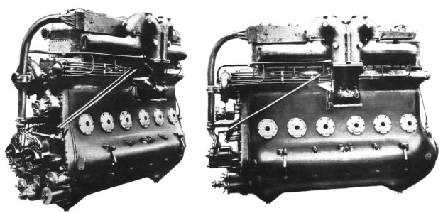
Beardmore’s first high-power, low rpm aircraft engine designed by Chorlton was really two engines, the Cyclone and the Typhoon, whose development ran parallel. The Beardmore Cyclone was a water-cooled, straight-six engine with a 8.625 in (219 mm) bore and a 12 in (305 mm) stroke, giving it a total displacement of 4,207 cu in (68.9 L). The Beardmore Typhoon was essentially the same engine but in an inverted configuration. Almost all parts were interchangeable between the two engines.

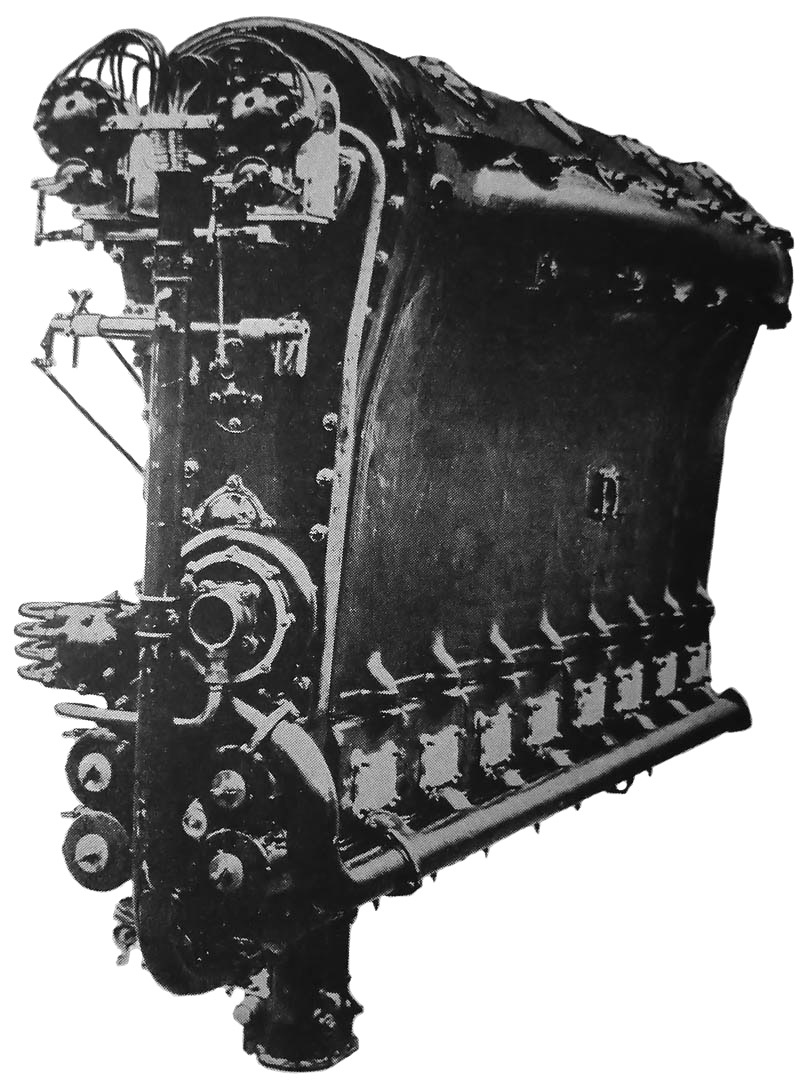
The Beardmore Typhoon inverted engine.
Both the Cyclone and Typhoon used an aluminum crankcase that also formed the cylinder block. Thin steel Cylinder liners were inserted into the crankcase toward the crankshaft. The cylinder liners were supported by a flange toward the cylinder head and sealed by a ring toward the crankshaft. Each cylinder had its own detachable head. The four valves per cylinder were actuated via rockers and short pushrods from the single camshaft, which ran along the side of the engine just below the head. For the Cyclone, the camshaft was on the right side of the engine but, being rotated 180-degrees to the inverted position, the camshaft was on the left side of the Typhoon (both when viewed from the rear).
Two spark plugs were fitted to the top of each cylinder and fired by two Watford C6SM magnetos. The magnetos along with the water, oil, and fuel pumps were driven off the rear of the engines by a series of intermediate gears. Aluminum pistons with three compression rings and one oil-scrapper ring were used. The compression ratio was 5.25 to 1.
The Cyclone I was first run in 1922 and generated 700 hp (522 kW) at 1,220 rpm. Development continued, and by 1927, the Cyclone II was producing 850 hp (634 kW) at 1,350 rpm but could produce 950 hp (708 kW) at the same rpm with a larger carburetor. Fuel consumption was .48 lb/hp/hr (292 g/kW/h), and the engine weighed 2,150 lb (975 kg). The Cyclone was 80.3 in (2 m) long, 35 in (.9 m) wide, and 61.125 in (1.55 m) tall. Reportedly, only one Cyclone II was built, and it was sold to Heinkel Flugzeugwerke in Germany.

The Typhoon in the Avro 549C Aldershot IV during an engine run.
As already mentioned, the Typhoon was an inverted version of the Cyclone. The date the engine was first run is not clear, but the Typhoon was mentioned along with the Cyclone in a Beardmore brochure from 1924. The Typhoon I (some say Typhoon II) originally produced 800 hp (597 kW) at 1,350 rpm but was developed to 925 hp (690 kW) at the same rpm by 1926. Fuel consumption was .46 lb/hp/hr (280 g/kW/h), and the engine weighed 2,233 lb (1,013 kg). The Typhoon was 80.3 in (2 m) long, 38.5 in (.98 m) wide, and 59.3 in (1.5 m) tall. The Typhoon was installed in an Avro 549 Aldershot (J6852), replacing the Napier Cub engine. The Typhoon-powered aircraft, re-designated Avro 549C Aldershot IV, first flew on 10 January 1927. After a demonstration flight on 24 January 1927, pilot Bert Hinkler reported that the Typhoon engine was remarkably smooth.

The Beardmore Typhoon-powered Avro 549C Aldershot IV flown by Bert Hinkler during a flight demonstration on 24 January 1927.

Reportedly, this image is of the 750 hp (559 kW), compression ignition Beardmore Typhoon.
A low-speed, large displacement engine design was very suitable for compression ignition, and another Typhoon engine was built as a diesel. Some sources report this engine as the Typhoon I, while others simply refer to it as the Typhoon C.I. In addition, the engine was sometimes noted as a semi-diesel (surface ignition). However, the power output of 750 hp (559 kW) at 1,400 rpm suggests that it was a true compression ignition diesel. Regardless, the diesel Typhoon was dimensionally the same as the standard Typhoon. The engine was under development along with the Cyclone and standard Typhoon and is mentioned in some of the articles regarding those engines. Some sources state that this engine was installed in the Avro 549 Aldershot, but that does not seem to be the case. No evidence has been found that this engine ever flew. However, in 1924, the Air Ministry ordered nine compression ignition Typhoons to be used in the R101 airship under construction. By 1926, the Air Ministry felt the Typhoon had reached its development potential and changed the order to the Beardmore Tornado engine, then under development.
The 1,100 hp (820 kW), 5,528 cu in (90.6 L), inverted, straight-eight, Beardmore Simoon aircraft engine.
The Beardmore Simoon engine was a further development of the standard Typhoon but was designed at the same time. Compared to the Typhoon, the Simoon’s bore was reduced to 8.5625 in (217.5 mm), but the stroke remained the same at 12 in (305 mm). However, two additional cylinders were added. This gave the inverted, straight- eight Simoon engine a total displacement of 5,528 cu in (90.6 L). The Simoon maintained the 5.25 to 1 compression ratio of the previous engines, and fuel consumption was .48 lb/hp/hr (292 g/kW/h). Normal output was 1,100 hp (820 kW) at 1,250 rpm, but 1,200 hp (895 kW) could be achieved at 1,350 rpm. The Simoon was 98 in (2.5 m) long, 37.6 in (.96 m) wide, and 72.6 in (1.84 m) tall. The Simoon’s height increase over the Cyclone and Typhoon was due to an additional sump protruding from the lower rear of the engine. The engine weighed 2,770 lb (1,256 kg). The Simoon was installed in the second Blackburn T.4 Cubaroo (N167), replacing a Napier Cub engine. The Simoon-powered Cubarro first flew early in 1927.
None of these large, low-speed, high power engines were a success, and only a small number were made.
Sources:
– Aerosphere 1939 by Glenn Angle (1940)
– Beardmore Aviation 1913-1930 by Charles Mac Kay (2012)
– Jane’s All the World’s Aircraft 1928 by C.G. Grey (1928)
– British Piston Aero Engines and their Aircraft by Alec Lumsden (1994/2003)
– Avro Aircraft since 1908 by A J Jackson (1965/1990)
– Blackburn Aircraft since 1909 by A J Jackson (1968/1989)
– “The Beardmore “Cyclone’ Aero Engine,” Flight (4 November 1926)
– “The Beardmore ‘Typhoon’ Mark I Engine,” Flight (27 January 1927)
– “The Beardmore Cyclone and Typhoon,” Flight (5 July 1928)
– “British Aero Engines,” Flight (29 May 1924)