Monthly Archives: June 2013

Piaggio P.23M front

Piaggio P.23M Transport Prototype

By William Pearce

The Piaggio P.23M was a prototype commercial transport aircraft intended for northern transatlantic flights. If flight testing was successful, the possibility existed to develop the unique aircraft for regular passenger service. Designed in 1934 by Giovanni Pegna, the P.23M was partly inspired by the Piaggio P.16 bomber prototype (also designed by Pegna). Two examples of the P.23M were ordered on 31 May 1934 and given the serial numbers MM 263 and MM 264.

Piaggio P.23M front

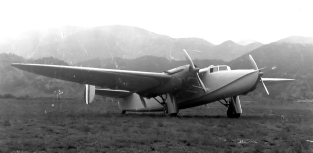
The elegant Piaggio P.23M transport prototype.Note the intakes above and below the spinner for funneling cooling air into the radiators for the tandem engines .

The P.23M was a four-engine, all-metal aircraft with twin tail fins and rudders. The underside of the aerodynamically clean fuselage had a keel, much like a flying boat, and was watertight. While the aircraft could not operate from the water, the keel fuselage design was incorporated to facilitate emergency water landings. This feature was reflected in the P.23M’s name, the “M” representing Marino (Marine) .

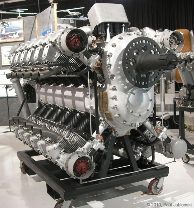
The P.23M’s wing was a semi-cantilever, inverted-gull design (similar to the P.16’s) and was supported by three struts on each side. Each wing carried a long nacelle that housed two Isotta-Fraschini Asso XI R engines mounted in tandem. The foreword engine drove a tractor propeller, and the rear engine drove a pusher propeller. Each nacelle also housed the radiators for the engine pair and the retractable main landing gear.

Piaggio P.23M side

The boat-like keel at the front of the P.23M’s fuselage can be seen fading toward the rear of the aircraft in this side view.

The Asso XI R engine was a 12-cylinder Vee with a 5.75 in (146 mm) bore and a 6.30 in (160 mm) stroke. Total displacement was 1,962 cu in (32.1 L), and the engine produced 900 hp (671 kW). The Piaggio P.23M had a wingspan of 88 ft 7 in (27.0 m) and was 54 ft 6 in (16.61 m) long. The aircraft’s empty weight was 16,290 lb (7,387 kg), and maximum weight was 40,651 lb (18,439 kg), resulting in an impressive useful load of 24,365 lb (11,052 kg). Calculated speeds were 249 mph (400 km/h) maximum and 186 mph (300 km/h) cruise. Cruising range was estimated at 3,167 miles (5,100 km). Climbing calculations indicated the P.23M could reach 13,125 ft (4,000 m) in 14 minutes.

The Piaggio P.23M first took to the air on 25 October 1935 at Villanova d’Albenga, Italy. Tragically, something during the flight went horribly wrong. The aircraft crashed, and both test pilots, Ciacci and Risso, were killed.

Piaggio P.23M rear

The P.23M’s inverted gull wing and twin tails can be seen in this rear view, along with the aerodynamically clean fuselage.

While the exact cause of the crash is not known, it could have had something to do with the aerodynamic effect of the tandem engines and propeller pulses on the twin tails. The design for the second P.23M (MM 264), which had not been built, was converted to a trimotor configuration and redesignated P.23T. As a further development of the P.23M, the Piaggio P.50 I heavy bomber retained the tandem engines in each nacelle, but the twin tails were replaced with a single tail. Subsequently, the P.50 II had a conventional layout for its four engines—each in a separate nacelle.

Ultimately, the P.23T trimotor transport proposal was abandoned, and an entirely new aircraft was designed and constructed as the P.23R. Despite the similar designation, the P.23R had nearly nothing in common with the P.23M. Neither the P.23 nor P.50 series of aircraft proved successful. However, they did provide much experience to facilitate development of the Piaggio P.108 heavy bomber of World War II.

Piaggio P.23M front 2

Another front view of the Piaggio P.23M. Note the right wing’s support struts and the missing cover on the left main gear.

Sources:
Italian Civil and Military Aircraft 1930-1945 by Jonathan W. Thompson (1963)
http://www.giemmesesto.org/Documentazione/Aerei/PIAGGIO_P-23.html
http://www.secretprojects.co.uk/forum/index.php?topic=15099.0
http://en.wikipedia.org/wiki/Piaggio_P.23

Allison X-4520 RRHTAB front

Allison X-4520 24-Cylinder Aircraft Engine

By William Pearce

When the United States entered World War I, the Allison Experimental Company (Allison), founded by James Allison, set out to construct equipment for the war effort. Previously, the company was known as the Allison Speedway Team Company, because James Allison was a co-founder of the Indianapolis Motor Speedway and was focused on automobile development. During the war, the Allison Experimental Company supplied some of the tooling for production of Liberty V-12 engines. Throughout and after the war, Allison was involved in designing and building various Liberty parts, including the epicyclic (planetary) gear reduction for the Liberty 12B (200 of which they constructed) and various other gear reduction units, gearboxes, and superchargers. Allison also developed and produced an inverted Liberty engine and air cooled cylinders for the Liberty. The Liberty was Allison’s first foray into aircraft propulsion; its next was the X-4520.

Allison X-4520 RRHTAB front

The restored Allison X-4520 24-cylinder, air-cooled engine carrying Allison serial number 1. Note the distributors on the front of each overhead camshaft.  (Paul Jablonski image via the Aircraft Engine Historical Society)

On 4 January 1921, the Allison Experimental Company changed its name to the Allison Engineering Company. By 1924, the Army Air Service (AAS) Power Plant Section at McCook Field, Ohio had designed a large 24-cylinder engine in an “X” layout. They asked Allison to refine their design and construct a prototype. The engine was given the AAS serial number 25-521 and also carried the Allison serial number 1.

The X-4520 had four banks of six air-cooled cylinders. The banks were arranged at 90 degree intervals around a common crankshaft housed in an aluminum, barrel-type crankcase. The cylinders had a 5.75 in (146 mm) bore, 7.25 in stroke (184 mm), and 4.9 to 1 compression ratio. Total displacement was 4,518 cu in (74 L). Each cylinder had two valves, and the exhaust valve was sodium cooled. The valves for each cylinder bank were actuated by a single overhead camshaft. At the front of each camshaft was a distributor that fired the two spark plugs per each cylinder for that bank. Each camshaft was driven by the crankshaft via a vertical shaft at the front of the engine.

Allison X-4520 AAS Early side sm

An early 1925 AAS drawing of the X-4520. The most notable differences between the drawing and the actual engine are that the drawing has the lower banks of cylinder staggered forward of the upper cylinders, and the intake manifolds exit the top and bottom of the rotary induction.

The flat top aluminum pistons had three rings above the piston pin and one ring below. Each of the six 3.5 in (89 mm) diameter crankpins was 4.3125 in (110 mm) long and accommodated two fork-and-blade connecting rods side-by-side. The top cylinder’s pistons were connected to the front fork-and-blade connecting rod. The bottom cylinders were staggered slightly to the rear, and their pistons were connected to the rear fork-and-blade connecting rod. The seven crankshaft main bearings were of the (Hoffman) roller type. Roller bearings were selected by the Power Plant Section because their reduced length allowed for a shorter, and therefore lighter, engine.

The engine had a 2 to 1 spur reduction gear and a rotary induction (fuel/air mixer or moderate supercharger) geared with a step-up ratio of 5 to 1. At 1,800 rpm engine speed, the propeller would turn 900 rpm and the supercharger 9,000 rpm. Two updraft carburetors fed the rotary induction at the rear of the engine. The air/fuel mixture was then distributed to each cylinder via manifolds that ran in the upper and lower Vees of the engine. The X-4520 was 108 in (2.74 m) long, 60 in (1.52 m) wide, 53 in (1.35 m) tall, and weighed around 2,800 lb (1,270 kg).

Allison X-4520 baffles

The Allison X-4520 with baffles surrounding sides of the engine to direct cooling air through the cylinder’s fins.

Allison completed the sole X-4520 engine in 1927, but no facilities existed that could handle the rated output of 1,200 hp (895 kW) at 1,800 rpm. At the time, it was one of the largest and most powerful aircraft engines ever built. It was not until 1931 that the engine was finally run by the Army Air Corps (AAC). While the engine produced 1,323 hp (987 kW) at 1,900 rpm, it also experienced cooling-issues, and a piston stuck in a cylinder during testing. By this time, the AAC had little interest in the engine, and the cause of the issues were never investigated.

The X-4520 was intended for a very large single-engine biplane bomber, most likely the Huff-Daland XHB-1. This aircraft had an 84 ft 7 in (25.8 m) span, was 59 ft 7 in (18.2 m) long, and was fitted with a 780 hp (582 kW) Packard 2A-2540 V-12 engine. By the time the X-4520 was tested, a design shift had occurred from the use of large single-engine aircraft to multi-engine aircraft. This left the X-4520 without an application, in addition to the technical issues experienced during testing.

Huff-Daland XHB-1

The huge Huff-Daland XHB-1 was originally to be powered by the X-4520. As events unfolded, the aircraft was powered by a Packard engine. The man standing under the nose of the aircraft gives a good indication of its immense size.

Even with the AAC’s lack of interest and the engine’s technical issues, the X-4520 was displayed at the Century of Progress Exposition in Chicago, Illinois in 1934. The engine was retained by the AAC and placed in storage at what would become Wright-Patterson Air Force Base in Dayton, Ohio. The X-4520 was disposed of as scrap around 1970 (apparently aviation history enthusiast Walter Spolata saved the engine). The X-4520 eventually found its way to the New England Air Museum in Windsor Locks, Connecticut, looking in rough shape after being in outside storage for a number of years. The engine was then acquired by the Rolls-Royce Heritage Trust Allison Branch in Indianapolis, Indiana; the trust restored the X-4520 and put it on display in 2010.

The restored Allison X-4520 on display at the Rolls-Royce Heritage Trust Allison Branch in Indianapolis, Indiana.

The Allison X-4520 on display at the Rolls-Royce Heritage Trust Allison Branch in Indianapolis, Indiana. Note the induction and how it differs from the 1925 drawing. (Paul Jablonski image via the Aircraft Engine Historical Society)

Sources:
Vee’s for Victory! The Story of the Allison V-1710 Aircraft Engine 1929-1948 by Daniel D. Whitney (1998)
Bearing Loads and Stress Analysis of the Model X-4520 Engine Rated 1200 B.H.P. at 1800 R.P.M. by Norman Tilley (1925)
The Allison Engine Catalog 1915-2007 by John M. Leonard (2008)
A Technical & Operational History of the Liberty Engine by Robert J. Neal (2009)
http://www.enginehistory.org/allison.shtml
http://www.nationalmuseum.af.mil/factsheets/factsheet.asp?id=2422