Monthly Archives: May 2014

Hispano-Suiza Type 86 engine

Hispano-Suiza Type 86 Railcar Engine

By William Pearce

In the mid-1930s, Hispano-Suiza developed the Type 86 engine specifically for use in railcars. A railcar is a self-propelled railroad coach meant to carry passengers or cargo on routes that are not profitable enough to operate a regular locomotive pulling non-powered railroad cars.

Hispano-Suiza Type 86 engine

The Hispano-Suiza Type 86 railcar engine. From left to right across the top of the engine are the fuel pump, air compressor, carburetor (another on the opposite side), two magnetos with a speed governor, and two starters above the housing on the right. The oil cooler is positioned under the cylinder head.

Hispano-Suiza became involved in powering railcars with the adaptation of its six-cylinder automotive Type 56 engine of 487 cu in (8.0 L) and 46 hp (34 kW). In 1931, the V-12 Type 68 auto engine was bored out and modified for use in French “Micheline” (rubber-tired) railcars. This engine displaced 690 cu in (11.3 L) and produced 250 hp (186 kW). Unlike the previous Hispano-Suiza engines, the Type 86 engine was specifically designed for use in railcars.

The Type 86 was a horizontal (flat) 12-cylinder engine. The engine was designed to keep its height to a minimum so that it could be mounted transversely in place of one of the railcar’s bogies. The railcar’s drive wheels were connected by hydraulic couplings to gearboxes on both ends of the engine. This installation maximized the usable space in the railcar while lowering its center of gravity. Engine accessories, such as the compressor, carburetors, magnetos, and starters, were placed on top of the engine for ease of access and maintenance.

Hispano-Suiza Type 86 crankcase.

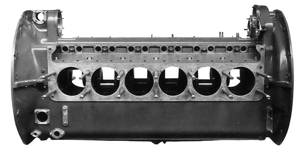
The two-piece aluminum crankcase for the Type 86 engine. Note the 14 long studs used to secure each cylinder bank to the engine.

With a 5.91 in (150 mm) bore and a 6.69 in (170 mm) stroke, the Type 86 displaced 2,200 cu in (36.05 L). The forged and hardened aluminum alloy flat top pistons had three compression rings and one scraper ring. Floating piston pins attached the pistons to tubular fork-and-blade connecting rods. The blade rod and its big-end cap meshed together through a tongue and grove design. Two tapered pins secured the blade rod around the crankshaft. The fork rod had a conventional big-end cap securing it around the crankshaft. Reportedly, these connecting rods and their bearings were the same as those used on some versions of the Hispano-Suiza 12Y V-12 aircraft engine. Although the Type 86 had the same bore and stroke as the 12Y, no other components were interchangeable.

The forged, chrome-nickel steel crankshaft was supported in the crankcase with seven main bearings and weighed 243 lb (110 kg). The single camshaft was positioned on top of the aluminum crankcase and was also supported by seven bearings. The camshaft was driven by the crankshaft via a helical spur gear at one end of the engine. This gear also drove the fuel pump and an air compressor for powering brakes and other accessories. At the other end of the engine, the camshaft drove two 12-cylinder magnetos and an engine speed governor.

Hispano-Suiza Type 86 crank and rods

The crankshaft and fork-and-blade connecting rods for the Type 86 engine. Note the blade rod with a tongue and groove design on the big end.

Each cylinder bank was attached to the crankcase by 14 long studs. Six open cylinder liners made of nitrided steel were installed in each aluminum cylinder bank. A single-piece, aluminum head (flathead) was attached to each cylinder bank by 50 bolts, in addition to the 14 long studs. The engine’s compression ratio was 5.85 to 1.

The intake and exhaust side valves were positioned parallel to and directly above the cylinder barrel. The valves opened into a small combustion space adjacent to the cylinder. The intake port and combustion chamber made the incoming air/fuel charge turbulent to allow for better mixing of gases. The chrome silicon valves were sodium-cooled and used three valve springs each. The valve seats were faced with Stellite for wear resistance. The valves were actuated by roller lifters. Two spark plugs were positioned in the cylinder head and directly above the valves. This position allowed the spark plugs to be easily accessed for maintenance.

Hispano-Suiza Type 86 head and cyl bank

At top is a complete cylinder bank assembly for the Type 86 engine. The middle image shows the same assembly as it would bolt on to the crankcase. At bottom is the flathead. Note the recessed space that formed the combustion chamber and allowed clearance for the side valves .

The Type 86 engine had pressure lubrication to all turning parts. Oil was drawn from the crankcase and sent though the engine via a pump located in the center of the crankcase. Two additional sump pumps drew oil from both ends of the crankcase. These pumps fed oil through oil coolers on both sides of the engine. The cooled oil was returned near the main pump in the crankcase.

A centrifugal water pump on each side of the engine drew cooling water from the radiator and through the oil cooler. After the water passed though the pump, it then flowed through the cylinder head and into the cylinder block via drilled passageways. The heated water would exit the top of the cylinder head via ports on both sides of the head and flow back to the radiator, positioned on the railcar.

Each side of the engine had one downdraft carburetor attached to an intake manifold located above the cylinder bank. Horizontal carburetors were proposed to reduce the engine’s height, but it is not known if they were ever used. The engine’s speed governor limited the engine to 2,500 rpm by regulating the butterflies of the carburetors. The exhaust manifold was also positioned above the cylinder bank, and its configuration varied depending on the engine’s installation.

Hispano-Suiza Type 86 intake and water pump

The downdraft carburetor, manifold, and water pump (not to scale) used on the Type 86 engine.

For starting the engine, the Type 86 used two 24 volt electric starters with a maximum speed of 3,500 rpm. The starters were geared to the engine at a reduction of 37 to 1 so that they would turn the engine over at less than 95 rpm. Although one starter could start the engine when it was warm, the starters acted in unison, and both were needed to start the engine when cold, turning the engine at 80 rpm.

Internal splines in each end of the crankshaft received a coupler used to connect the engine to a gearbox. The couplers used hydraulic clutches, and one of the two couplers had a ring gear for starting the engine. The couplers were not mechanically locked at full load, which ensured smooth transmission of power to the gearboxes. Each gearbox used electromagnetic gear selection for its planetary gear reduction. At one engine revolution, the four gear reduction speeds were 0.237, 0.389, 0.610, and 1.0.

Hispano-Suiza Type 86 cam piston and lifter

While not to scale, the camshaft, piston, and roller lifter for the Type 86 engine can be seen in the above image. Note the adjustment rod on the roller lifter to provide proper valve clearance.

With interruptions only for routine maintenance, the Type 86 was designed to provide continuous service for about a year, traveling 310–375 mi (500–600 km) per day. That service life worked out to around 125,000 mi (200,000 km) before an overhaul was scheduled. The power section of the engine was 58.1 in (1.475 m) long but grew to 122.4 in (3.109 m) with the couplers and gearboxes. The engine was 40.3 in (1.024 m) wide and 39.1 in (.993 m) tall. The Type 86 produced a continuous 550 hp (410 kW) at its normal operating speed of 2,000 rpm. But the engine could produce 650 hp (485 kW) at 2,000 rpm and 750 hp (560 kW) at 2,200 rpm.

A smaller engine called the Type 87 was also planned. This engine’s bore was reduced by 1.18 in (30 mm) to 4.72 in (120 mm). As a result, its total displacement was reduced by 792 cu in (12.98 L) to 1,408 cu in (23.07 L). It was believed this engine would develop 330 hp (246 kW). However, in the late 1930s, French industries were focused on rearming the French military, and few resources were available for other projects. Hispano-Suiza directed its attention to manufacturing aircraft engines, and development of the railcar engines was stopped.

Hispano-Suiza Type 86 GA

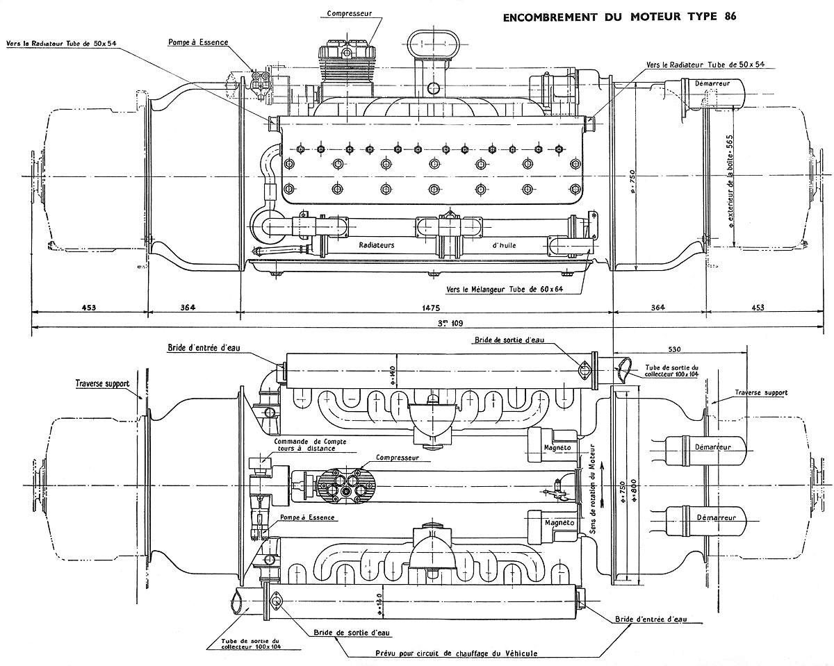
Side and top view drawings of the Hispano-Suiza Type 86 engine.

Sources:
Notice Descriptive du Moteur Hispano Suiza Type 86 by Hispano-Suiza (~1936)
Hispano Suiza in Aeronautics by Manuel Lage (2004)

Northrop YC-125 JATO

Northrop N-23 Pioneer and N-32 / YC-125 Raider

By William Pearce

As World War II wound down, Northrop looked for opportunities to expand its aviation products. At the time, various reports forecasted a need for a rugged, low-cost, transport aircraft to serve under-developed airfields for emerging commercial routes following World War II. To meet that need, Northrop designed and built the N-23 Pioneer transport at its own expense. The Pioneer was unlike any aircraft that Northrop had built.

Northrop N-23 Pioneer

The Northrop N-23 Pioneer seen shortly after its rollout at Hawthorne, California and before its registration (NX8500H) was applied. Note the single window along the fuselage.

The N-23 Pioneer was a trimotor, high-wing aircraft of all-metal construction. Its robust fixed landing gear, with long struts, enabled the aircraft’s use on unimproved runways. To allow for short-field operation, large flaps made up 80% of the wing’s trailing edge. In addition, another wheel could be added to the inboard side of each main gear strut to reduce the aircraft’s load footprint for soft field operation. Outboard of the large flaps were small ailerons that acted with wing spoilers to control the aircraft’s roll. This configuration was similar to that used on the Northrop P-61 Black Widow.

The Pioneer was engineered with remote field operations in mind. Common parts were used when possible; all three engine installations were identical, as were the vertical and horizontal stabilizers. The Pioneer was designed with large panels to allow easy access to critical parts for maintenance and repair.

Northrop N-23 take off

The Northrop Pioneer performing a short field takeoff from the Conejo Valley Airport in Southern California. The Pioneer’s short field performance enabled it to operate out of airfields normally limited to small aircraft. Note that the fuselage has been modified with passenger windows.

The Pioneer could be fitted with 36 seats for passenger service or carry up to 10,000 lb (4,536 kg) of cargo. Quick-change fittings were featured in the floor of the Pioneer’s cabin; they enabled easy reconfiguration of the aircraft’s interior from passenger transport to cargo transport. Long objects (such as pipe or timber) up to 36 ft (11 m) could be loaded through a hatch under the aircraft’s nose.

The Pioneer was powered by three 800 hp (597 kW) Wright R-1300 engines. Each engine turned a fixed-pitch, two-blade Hamilton Standard propeller. The aircraft had an 85 ft (25.9 m) wingspan and was 60 ft 7 in (18.4 m) long. It had a maximum speed of 193 mph (311 km/h), a cruising speed of 150 mph (241 km/h), and a range of 1,750 mi (2,816 km).

Northrop YC-125 Raider

YC-125 Raiders on the Northrop production line. Note the various engine access panels. The wings’ leading edge panels allowed access to fuel lines, control cables, and wiring.

First flown on 21 December 1946 by Max Stanley, the Pioneer proved to be a very capable aircraft. It could take off in fewer than 400 ft (122 m). At a gross weight of 25,500 lb (11,567 kg), the Pioneer could take off in 700 ft (213 m) and land in 600 ft (183 m). The aircraft was operated out of various unimproved and short fields in Southern California. Unfortunately, with the influx of cheap, surplus World War II transports available in the post-war marketplace, there was little interest in the rugged Pioneer.

After a year of test flights, the Pioneer was used to test an experimental dorsal fin. During a flight on 19 February 1948, the fin broke loose and damaged the Pioneer’s tail surfaces, making the aircraft uncontrollable. Test pilot Latham A. “Slim” Perrett did what he could to steady the aircraft to allow the copilot and an engineer to parachute to safety. Sadly, there was no time for Perrett to escape.

Northrop YC-125 air

A Northrop YC-125B on a flight by the coast. Note the redesigned empennage compared to the Pioneer.

Despite the crash, the Air Force was interested in the Pioneer’s capabilities. In March 1948, Northrop was issued a contract for 13 aircraft developed from the Pioneer. The new aircraft was the N-32 Raider and was designated YC-125 by the Air Force. The first version was the YC-125A, an assault transport. An order for 10 additional YC-125B aircraft followed. The YC-125B was intended for Arctic rescue. The two versions of the YC-125 differed only in internal equipment.

Northrop YC-125 JATO

A Northrop YC-125 Raider uses six JATO bottles to take off fully loaded in under 500 ft (152 m).

The YC-125 Raider was very similar to the Pioneer, but it had a redesigned rear fuselage that incorporated a 9 ft (2.7 m) by 6 ft 6 in (2.0 m) ramp for loading and unloading equipment. The addition of the loading ramp led to a redesign of the aircraft’s empennage. The YC-125’s tailwheel strut could be extended to allow for better loading ramp access. Six JATO (jet-assisted take off) bottles could be used to enable a fully loaded 40,900 lb (15,552 kg) YC-125 to take off in 500 ft (152 m).

The YC-125 was powered by three 1,200 hp (895 kW) Wright R-1820 engines. Each engine turned a constant speed, three-blade Curtiss Electric propeller. The propellers’ pitch could be reversed to shorten the landing distance to as little as 330 ft (100 m). The aircraft had an 86 ft 6 in (26.4 m) wingspan and was 67 ft 1 in (20.4 m) long. The YC-125 had a maximum speed of 207 mph (333 km/h) and a cruising speed of 171 mph (275 km/h). The aircraft’s maximum range was 1,850 mi (2,977 km), and it could carry 32 troops or 12,000 lb (5,443 kg) of cargo.

The YC-125 made its first flight on 1 August 1949 with Stanley at the controls. Initial flight tests went well, and all 23 aircraft were delivered to the Air Force by the end of 1950. However, the YC-125 was found to be underpowered during service trials. As a result, the aircraft was thought to have little use in its intended roles. The Air Force had other, more versatile aircraft and helicopters that could be used in place of the YC-125s. Soon, all YC-125s were stationed at Sheppard Air Force Base in Texas and used for ground instructional training. In 1955, they were declared surplus, and around 19 YC-125s were sold to Frank Ambrose Aviation in Florida. That company then resold many of the YC-125s to various entities in South America, where they were used as rough field transports. Some served into the 1970s, doing the type of work for which the N-23 Pioneer was originally designed.

Northrop YC-125A Pima

The Northrop YC-125A of the Pima Air & Space Museum. This aircraft was donated by Robert A. Gallaher. (Pima Air & Space Museum image)

There are two known surviving YC-125s. Both were recovered after their service in South America. The Pima Air & Space Museum in Tuscon, Arizona has a YC-125A still in the livery it wore while serving for Triplay y Maderas de Durango, S.A., a lumber company in Durango, Mexico. The National Museum of the United States Air Force (NMUSAF) in Dayton, Ohio has a YC-125B. This aircraft was recovered from Zacateas, Mexico by Asher Ward and Darryl Greenamyer in the early 1990s.

Ward and Greenamyer had previously recovered a YC-125A for the NMUSAF, but the aircraft crashed in Tulsa, Oklahoma on 29 June 1988. As a result of a corroded wire, the propeller of the left engine went into reverse pitch shortly after takeoff. Ward and Greenamyer escaped with minor injuries. This was the last flight of the last airworthy YC-125.

Northrop YC-125B NMUSAF

The Northrop YC-125B of the National Museum of the United States Air Force. Note the additional main wheel added to the inboard side of each main gear strut. (NMUSAF image)

Sources:
Northrop: An Aeronautical History by Fred Anderson (1976)
American Military Transport Aircraft Since 1925 by E. R. Johnson (2013)
http://www.nationalmuseum.af.mil/factsheets/factsheet.asp?id=784
http://www.warbirdinformationexchange.org/phpBB3/viewtopic.php?p=167612
http://newsok.com/rare-airplane-loses-power-crashes-at-airport-in-tulsa/article/2230816
http://www.ntsb.gov/aviationquery/brief.aspx?ev_id=20001213X25943&key=1