By William Pearce
During World War I, Ettore Bugatti designed and built a U-16 aircraft engine. The engine consisted of two inline eight-cylinder sections mounted side-by-side on a common crankcase. Each eight-cylinder engine section had its own crankshaft and was built up of two four-cylinder blocks. The engine’s two crankshafts directly engaged a common propeller shaft. The Bugatti U-16 engine had a 4.33 in (110 mm) bore and a 6.30 in (160 mm) stroke. Total displacement was 1,485 cu in (24.3 L), and the engine produced 400 hp (298 kW) at 2,100 rpm.

Two 16-cylinder engines positioned front-to-front comprised the Bréguet-Bugatti 32A (Quadimoteur Type A). From the gearbox between the two engines, the propeller shaft extended between the cylinder banks of the front (lower) engine. (Musée de l’Air et de l’Espace image via The Bugatti 100P Record Plane)
Each group of four cylinders had one carburetor attached to an intake manifold on the outside of the engine. The exhaust manifolds were between the cylinder banks. Two spark plugs for each cylinder were positioned on the intake side of the engine, and each cylinder had two intake valves and one exhaust valve. The valves were actuated by a single overhead camshaft that was driven via beveled gears by a vertical shaft positioned between the two blocks of four-cylinders that comprised the eight-cylinder engine section. The vertical shaft also drove the engine’s magnetos. Water was circulated through the engine by pumps driven at the rear of each crankshaft. A single housing for the camshaft served both four-cylinder blocks on one side of the engine.
Bugatti did not have the production capacity to manufacture the engine, so licensed production was undertaken in France by a group headed by Peugeot. An additional license was sold to the United States (the engine was built as the King-Bugatti by Duesenberg). Developmental and production issues resulted in few Bugatti-based U-16 engines being built during World War I. After the war, the licensed manufacturers moved on to other projects, and the French aviation firm Bréguet (Société des Ateliers d’Aviation Louis Bréguet) took over development of the Bugatti U-16 engine in 1919.

The Bréguet Type XXI Leviathan airframe fitted with the Bréguet-Bugatti 32A engine at the Salon de l’Aviation in Paris in 1921. The 32A installation in the Type XX was essentially the same. Note the U-16 engine to the left.
Bréguet made a few modifications to the Bugatti U-16 engine. Their first U-16 engines had a 4.25 in (108 mm) bore and a 6.30 in (160 mm) stroke. Total displacement was decreased by 54 cu in (.8 L) to 1,431 cu in (23.5 L), and the engine produced 480 hp (358 kW) at 2,150 rpm. A further development of the U-16 engine was the U.24. The U.24 engine had a 4.25 in (108 mm) bore and a 6.42 in (163 mm) stroke. Total displacement was 1,458 cu in (23.9 L), and the engine reportedly achieved 600 hp (447 kW) at 2,800 rpm.
A major change with the U.24 was how the propeller shaft was driven. In the original engine, if one of the two eight-cylinder sections were to fail, it would cause the entire engine to stop because the crankshafts were directly geared to the propeller shaft. In the Bréguet-Bugatti U.24 engine, the crankshafts drove the propeller shaft through freewheeling (or overrunning) clutch mechanisms. If one eight-cylinder engine section were to fail, the clutch would simply disengage the dead section’s crankshaft from driving the propeller shaft and allow the good engine section to continue to produce power. The two engine sections did share a common oil supply, so they were not completely independent.

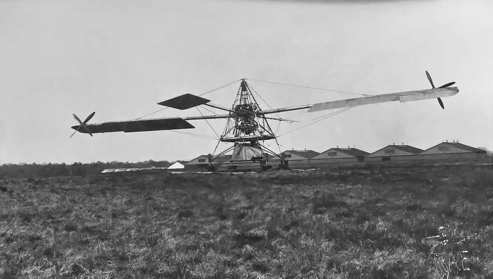
The Bréguet Type XX Leviathan powered by the 32A engine. Note the large radiator above the nose of the aircraft. The four exhaust ports (and a fair amount of soot) can be seen below the radiator. Each cylinder bank has its own exhaust manifold, and they all exit on the left side of the aircraft. The pilots can be seen above the “E” of the aircraft’s registration. (Pierre Bregerie image via 1000aircraftphotos.com)
Bréguet envisioned grand applications for their engines, and in 1920, they devised the concept of coupling two U.24 engines (although the bore and stroke are given as 4.33 in/110 mm and 6.30 in/160 mm respectively) to power one propeller. The engines were positioned in tandem, front-to-front, with the rear engine slightly higher than the front engine. Each crankshaft was coupled to a gearbox between the two engines. A freewheeling clutch system was again used so that if any of the four eight-cylinder banks were to fail, the dead crankshaft would automatically decouple, and the remaining banks would continue to provide power.
If the dead engine bank was repaired, it could be recoupled to the propeller shaft. In line with each crankshaft was a sleeve that was permanently engaged to the propeller shaft. The sleeve was keyed so that the coupling on the end of the crankshaft could only engage it at a desired orientation. After the uncoupled engine section was started and brought up to the same rpm as the engine, an operator would pull a lever to slide the coupling on the crankshaft and reengage that crankshaft to the propeller shaft. However, even with the keyway, the crankshaft of a four-stroke engine could be coupled 360 degrees out of sync. To prevent this, a lead was attached to various spark plugs and would indicate when the lever should be thrown to recouple the crankshaft of the desired bank. This ensured the coupling would take place at the right time to maintain the desired firing order and power pulses of the engine sections upon the propeller shaft.

This view of the Bréguet-Bugatti 32B (Quadrimoteur Type B) illustrates how two crankcase top haves of a U-16 engine are mounted on a common crankcase center section. This method of construction keeps the engine fairly modular: two four-cylinder blocks make up one bank; two banks on a common crankcase make up a U-16 top half; two U-16 top haves make up the 32B engine. (Aerofosslle2012 image via flickr.com)
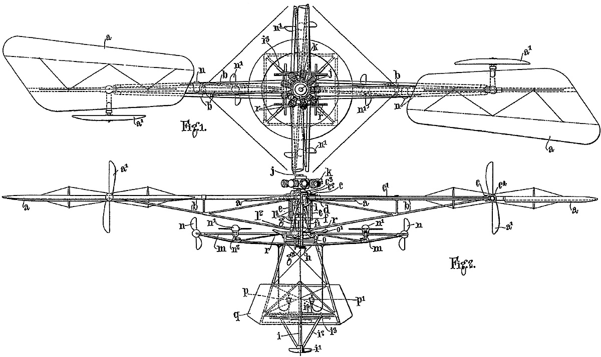
The propeller shaft extended from the middle of the gearbox, ran between the cylinder banks of the front engine, and led to the propeller. Helical gears were used, and the gearbox incorporated a .5 to 1 reduction in speed. It is interesting to note that patent drawings show a configuration in which the front engine is higher than the rear engine and the propeller shaft passes below the front engine. However, this configuration was not used.
The engine group was known as the Bréguet-Bugatti 32A (or Quadimoteur Type A), and its output varies by source from 850 to 1,000 hp (634 to 746 kW). It is possible that all outputs were realized at different rpms—the 850 hp (634 kW) figure was achieved at 2,000 rpm. With a 4.33 in (110 mm) bore and 6.30 in (160 mm) stroke, the 32A displaced 2,969 cu in (48.7 L). The engine’s compression ratio was 4.2 to 1, and it weighed 2,482 lb (1,126 kg).
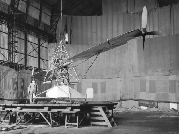
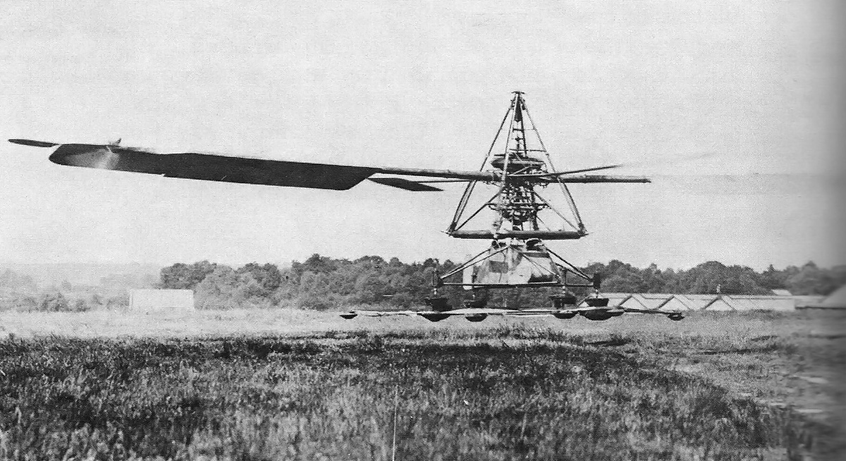
First run in 1921, a 32A engine was installed in the fuselage of the Bréguet Type XX Leviathan. The Type XX was an all-metal, biplane transport designed to carry 20 passengers. Compared to a standard twin-engine arrangement, the engine’s fuselage installation allowed for better aircraft streamlining, eliminated asymmetric thrust, and allowed the engines to be serviced while in flight. The engines turned two 14 ft 9 in (4.5 m) diameter two-blade propellers that were mounted in tandem. The Type XX had an 83 ft 7 in (25.54 m) wingspan and a length of 46 ft (14.02 m). The aircraft’s top speed was 118 mph (190 km/h), and it cruised at 99 mph (160 km/h).

The rear of the Bréguet-Bugatti 32B engine displayed in the engine mount used on the Type XXI Leviathan. The various levers controlled the manual coupling and decoupling of the crankshafts to the propeller shaft. (John Martin image via the Aircraft Engine Historical Society)
The sole Type XX first flew on 20 June 1922 with Bréguet test pilot Robert Thiéry at the controls. Flight testing went well, and the aircraft competed in the Grand Prix des Avions de Transport in November. On 14 November, the aircraft had the point lead when trouble occurred and it was forced down. There was little damage to the Type XX, but the aircraft could no longer win the Grand Prix. Apparently, the trouble occurred when one engine bank was shut down to replace its spark plugs, and a mechanic inadvertently shut down a second engine bank. The lack of power resulted in the emergency landing. Some sources state the aircraft was later destroyed during testing, but little information has been found regarding this claim. However, In September 1923, the Type XXII Leviathan of very similar construction (but with conventional engines installed between the wings) was destroyed during testing.
By 1924, Bréguet had moved on from the 32A’s cumbersome coupled engine concept and developed the Bréguet-Bugatti 32B (or Quadimoteur Type B) engine. Rather than having two separate engines, the 32B consisted of two U-16 crankcase top halves mounted on a common crankcase. The engine was configured as an H-32 in which one of the 16-cylinder crankcase halves was mounted in the normal vertical position, and the other was inverted. Each of the crankcase halves had two banks of eight cylinders, and each cylinder bank still had its own crankshaft. At the rear of the engine was a gearbox in which the four crankshafts were geared to a common propeller shaft at a .5 to 1 speed reduction. The gearbox employed the same coupling technique used with the 32A engine. Again, if a power section were to fail, that crankshaft would automatically decouple, and the remaining crankshafts would continue to provide power to the propeller shaft. The clutches also served to dampen vibrations between the individual crankshafts and the propeller shaft. The propeller shaft passed through the crankcase to drive the propeller at the front of the engine.
With the exception of the crankcase and propeller shaft, the 32B was very similar to the 32A and U-16 engines. One change was that each end of the camshafts drove a magneto. The cylinders had a 4.25 in (108 mm) bore and a 6.30 in (160 mm) stroke. The 32B had a total displacement of 2,862 cu in (46.9 L) and a compression ratio of 5.5 to 1. The engine produced 950 hp (708 kW) at 2,100 rpm and was tested to 1,015 hp (757 kW) in 1925. However, some sources indicate 1,200 hp (895 kW) was achieved at 2,800 rpm. The engine weighed 2,403 lb (1,090 kg).

The drive gears at the rear of the Bréguet-Bugatti 32B shown while the engine was under restoration. The image on the right shows the four crankshafts with their notched helical gears. The gears could slide on the crankshaft to couple or decouple with the propeller shaft, which is seen at the center of the crankcase. The image on the right shows the notched helical gears on the end of the propeller shaft. (l’Association Des Amis Du Musée Safran image)
Bréguet also built the Type XXI Leviathan, which was a military version (bomber) of the Type XX. In 1921 and 1922, the airframe of this aircraft was exhibited at the Salon de l’Aviation in Paris with the 32A engine installed—the same power plant used in the Type XX. However, the 32A engine in the Type XXI was substituted for a 32B. Unfortunately, little information has been found on the sole Bréguet Type XXI and its flying history. It is not clear when the 32A engine was removed and the 32B engine installed; presumably, it was not before 1925.
A large engine housed in the fuselage was found to take up too much space and did not yield much, if any, benefit. Bréguet subsequently refocused on conventional power plant arrangements. In addition, Bréguet did not see much of a return from its foray into aircraft engine design and manufacturing. The firm exited the aircraft engine business around 1926.
A Bréguet-Bugatti 32A (or Quadimoteur Type A) engine is in storage at the Musée de l’Air et de l’Espace in le Bourget (near Paris), France. This appears to be the engine that was installed in the Type XX aircraft. Probably only one or two of these engines were built. Also at the Musée de l’Air et de l’Espace is the Bréguet-Bugatti 32B (or Quadimoteur Type B), still in the engine mount for the Type XXI Leviathan. The 32B engine may be in storage, but it was displayed in the Hall de l’entre deux guerres. Most likely, only one 32B engine was built.

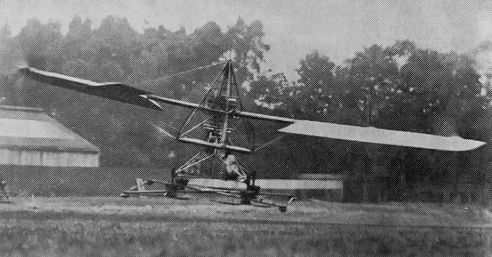
A rare image of the Bréguet Type XXI Leviathan with the Bréguet-Bugatti 32B engine installed. The aircraft was very similar to the Type XX, but with different wing struts. The frame of a gunner’s station is visible just behind the cockpit. (J. P. Mathieu image via Pyperpote)
Sources:
– The Bugatti 100P Record Plane by Jaap Horst (2013)
– Bugatti – The Designer by Barry Eaglesfield (2013)
– Les Moteurs a Pistons Aeronautiques Francais Tome I by Alfred Bodemer and Robert Laugier (1987)
– Jane’s All the World’s Aircraft 1922 by C.G. Grey (1922)
– “Device for the Automatic Coupling and Uncoupling of Engines Operating Upon a Common Propeller” U.S. patent 1,564,516 by Louis Breguet (granted 8 December 1925)
– “Moteur Breguet-Bugatti 32B” l’Association Des Amis Du Musée Safran Bulletin No 15 (May 2012)
– “The Breguet Leviathan Type XX” by E. H. Lemonon Aviation (25 April 1921)
– http://www.pyperpote.tonsite.biz/listinmae/index.php?option=com_content&view=article&id=174:moteur-breguet-bugatti-32b&catid=41:hall-e-apres-guerresaint-exuperyaviation-civi&Itemid=54
– http://1000aircraftphotos.com/Contributions/BregeriePierre/9609.htm