Category Archives: Rotorcraft

Hughes XH-17 hover front

Hughes (Kellett) XH-17 Heavy-Lift Helicopter

By William Pearce

On 31 January 1946, the Unites States Army Air Force issued a Request for Proposal involving the design of a heavy-lift helicopter capable of transporting a 10,000 lb (4,536 kg) external load. Additional specifications include the use of jet turbine propulsion and rotors equipped with tip jets. The Kellett Aircraft Corporation of Upper Derby, Pennsylvania was awarded a design contract on 2 May 1946, and the new helicopter was designated XR-17. If all went well with the XR-17’s design, a contract to build a test rig would be issued.

Hughes XH-17 side

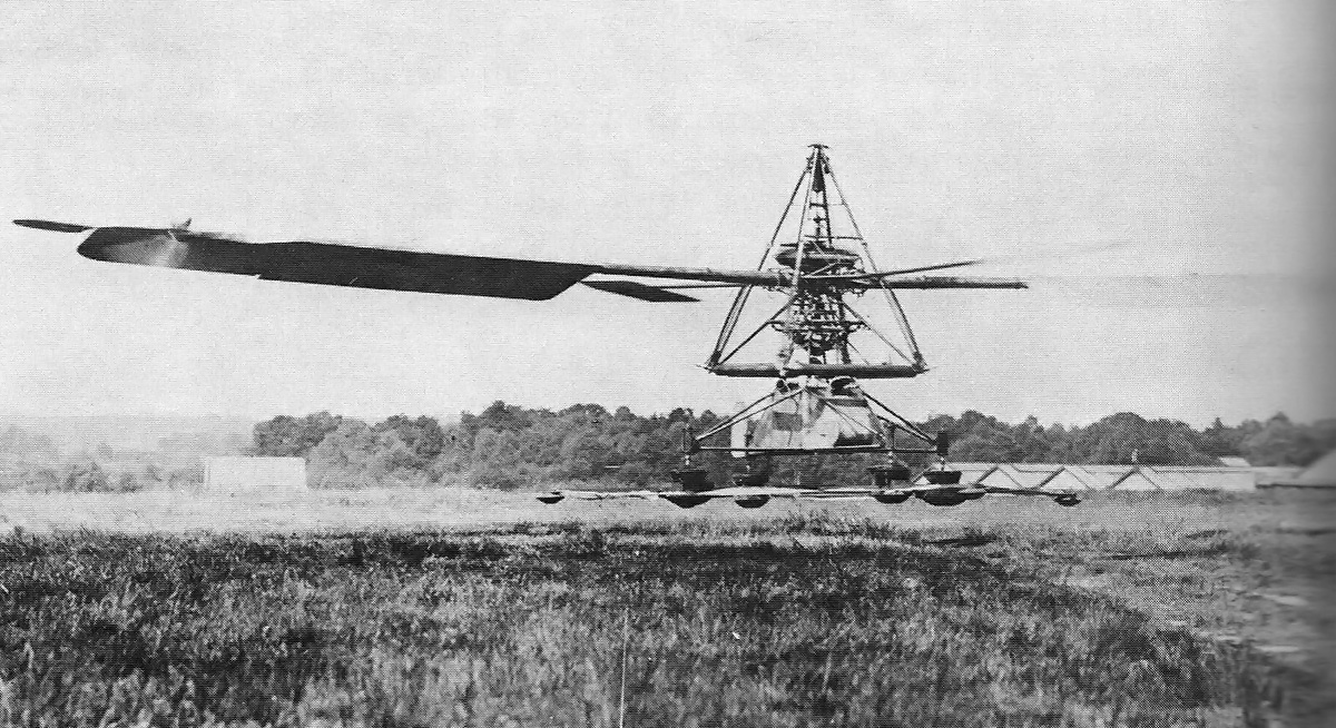
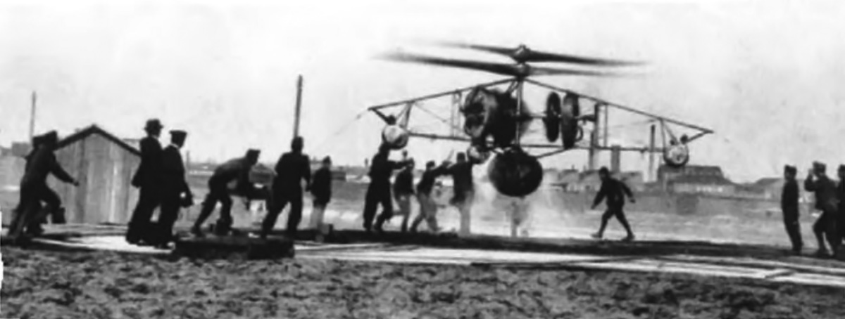
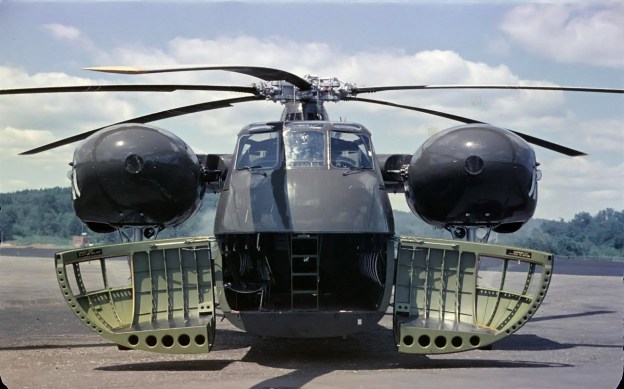
The massive Hughes XH-17 sits at rest before its first public flight on 23 October 1952. The notches in the rotor blade are where jets of pressurized air exit the rotor. (LIFE image via Google)

Kellett moved forward with the XR-17 design, which was centered around a pair of 4,000 lbf (17.79 kN) General Electric J35 (TG-180) engines driving a two-blade rotor. However, the engines were not mechanically attached to the rotors. Air was bled off from the compressor section of the modified engines and was ducted through the hollow rotors. The 400°F (204°C) air was exhausted from each rotor via four pressure-jets in the tip’s trailing edge. The jet of air emanating from the rotor tips caused the rotors to turn. This propulsion system was referred to as cold-cycle pressure-jet, because the air from the engine’s compressor section was much cooler than the air from the engine’s exhaust. To further augment power, General Electric GE33F pressure-jet burners sprayed and ignited fuel into the jet of air exiting the rotor. Kellett estimated that 1,000 hp (746 kW) was produced with the cold-cycle air jet alone, and 3,480 hp (2,595 kW) was produced with the tip burners in use.

By 27 August 1947, the XR-17 design had progressed well, and Kellett was awarded a contract to produce a test rig of the helicopter’s rotor system. Kellett went to work constructing the test rig and tried to save money wherever possible by using components of other aircraft. The company was having financial issues, and the XR-17 project had an uncertain future.

Hughes XH-17 group

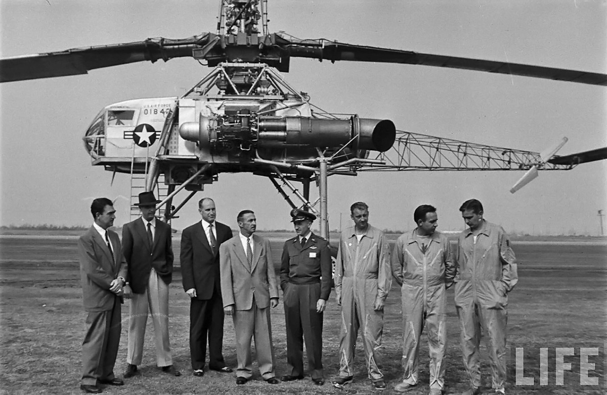
From left to right: Rea Hopper, Howard Hughes, Clyde Jones, Warren Reed, Colonel Carl Jackson, Gale Moore, Chalmer Bowen, and Marion Wallace. (LIFE image via Google)

In June 1948, the helicopter was redesignated XH-17. Through 1948, work continued on the XH-17 test rig, but the financial issues at Kellett only worsened. With the Air Force’s blessing, Hughes Aircraft purchased the XH-17 project and moved all materials and many Kellett personnel to Culver City, California. Work on the XH-17 resumed in March 1949 and progressed rapidly with full support from Hughes.

The Hughes XH-17 consisted of a cockpit from a Waco CG-15 glider attached to a custom-built tube steel frame. Its steerable front landing gear was made using the main wheels from a North American B-25 Mitchell, and its rear landing gear was made using the main wheels from a Douglas C-54 Skymaster. The XH-17’s fuel tank was originally a 636-gallon (2,408-L) extended-range bomb bay tank for a Boeing B-29 Superfortress. The helicopter’s 130 ft (39.62 m) two-blade main rotor turned at 88 rpm. Each blade was 12 in (.30 m) thick, 58 in (1.47 m) wide, and weighed 5,000 lb (2,268 kg). The large pressure-jet rotors had a very short fatigue life.

Hughes XH-17 rear

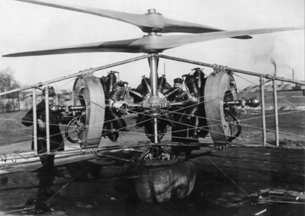
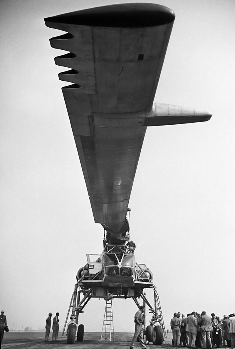
Rear view of the XH-17 illustrating the helicopter’s tube frame construction and relatively small tail rotor. (LIFE image via Google)

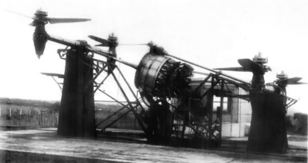
The XH-17 test rig was run for the first time around October 1949. Only bleed air was used to turn the rotors. After about three months of testing, the rotor burners were fired for the first time on 22 December 1949. This created a very a loud whop-whop-whop noise that coincided with the passing of each set of lit burners on the rotors’ tips. The noise was so loud that it could be heard eight miles (13 km) away, and the XH-17 caused numerous noise complaints to be filed against Hughes.

Hughes XH-17 front


The XH-17’s wide stance was to facilitate positioning equipment under the helicopter. Note the large horn balance on the rotor’s leading edge. The stress and vibration of operating the 130 ft (39.62 m) rotor gave the blades a very short life. (LIFE image via Google)

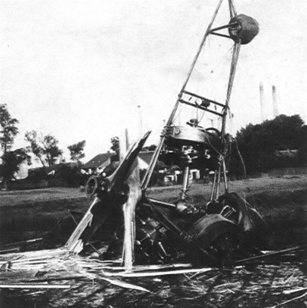
Testing of the rig steadily progressed until June 1950, when a control link broke and caused the XH-17 test rig to rise about 10 feet (3 m) off the ground before it crashed back down. The rig was damaged, but the rotors and power system were unharmed. Rather than just rebuild the test rig, the decision had already been made to convert the rig into a flight-capable helicopter. Numerous systems were revised, and a tail rotor from a Sikorsky H-19 Chickasaw was added. The tail rotor was small compared to the rest of the XH-17. The rotor jets did not create a major torque reaction that needed to be counteracted like the main rotors of a conventional helicopter. The tail rotor was mainly for differential directional control. The wide-set and tall landing gear allowed loads to be driven under the helicopter and then attached for lifting.

The XH-17 was ready for flight in the summer of 1952. The complete helicopter was 53 ft 4 in (16.55 m) long and 30 ft 2 in (9.17 m) tall. The XH-17 had an estimated top speed of 90 mph (145 km/h) and a range of only 40 miles (64 km), due to the high fuel consumption of the rotor’s pressure-jet burner system. The helicopter had a normal weight of around 41,700 lb (18,915 kg) and a maximum weight with a 10,284 lb (4,665 kg) payload of 52,000 lb (23,587 kg).

Hughes XH-17 hover front

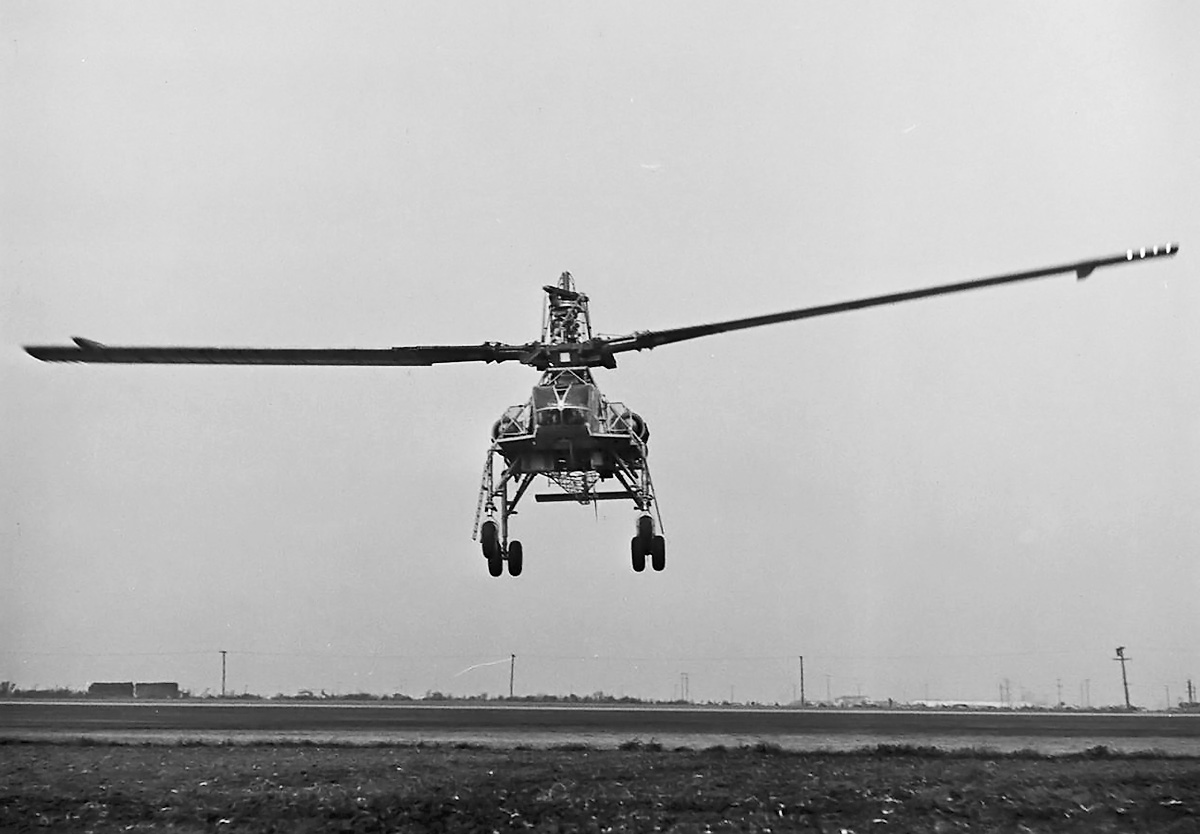
The XH-17 was a rather awkward-looking machine, and it is easy to see why it was referred to as “Monster.” The glowing spots on the rotor blade’s tip are the pressure-jet burners. (LIFE image via Google)

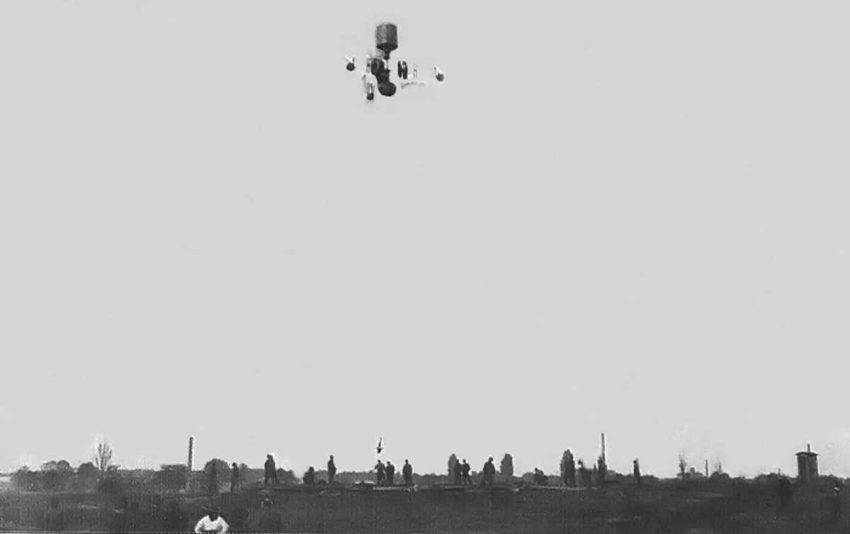
During a test on 16 September 1952, the XH-17 made its first unofficial flight. Piloted by Gale Moore and Chalmer Bowen, the helicopter was accidently bounced off the ground during a hover test due to overly-sensitive controls. The controls were modified, and a much more controlled hover was established the following day. The XH-17 made its public debut on 23 October 1952 at Hughes Airport in Culver City. Two flights were made that day, and the XH-17 hovered, flew forward up to 45 mph (72 km/h), flew backward, and rotated 360 degrees. Moore and Bowen were again the pilots and were joined by Marion Wallace. They had nicknamed the XH-17 “Monster” on account of its odd appearance, but the helicopter was also known as the “Flying Crane.”

As the XH-17 program was progressing, the Air Force asked Hughes to design an improved and more powerful version in October 1951. The new helicopter was designated XH-28 and would use a cold-cycle rotor system with pressure-jet burners, similar to the arrangement on the XH-17 but with four blades. Power was provided by two Allison XT40-A-8 turboprop engines. Each 5,300 hp (3,952 kW) XT40 engine consisted of two T38 engines coupled to a common gear reduction. The engines in the XH-28 would drive a compressor unit to send air to the rotors. The XH-28 would weigh 52,000 lb (23,587 kg) empty and would be capable of lifting 50,000 lb (22,680 kg), for a total gross weight of 105,000 lb (47,627 kg). The Air Force awarded a design contract for the XH-28 to Hughes in January 1952.

Hughes XH-17 hover side

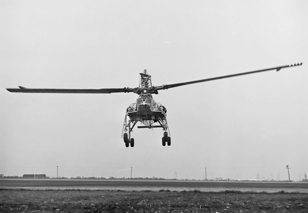
The blades of the XH-17 operating at 88 rpm were easily distinguished, even when the helicopter was in flight. Note the glow of the tip burners and the size of the GE J35 engine. (LIFE image via Google)

A XH-28 mockup was constructed, and extensive testing was involved to create rotors with an extended fatigue life. Ultimately, rotors of a bonded titanium construction were chosen. Allison was hesitant to devote engineering resources to the engine design because the company was involved with so many other projects that it felt held more promise. In December 1952, the Air Force decided that its funds should be spent on jet fighters and bombers and that it would not support the XH-28 beyond 1953. The Air Force was willing to hand the project over to the Army, which was interested in the XH-28 as a way to transport tanks and other equipment. However, the Army soon decided that its funds would be better spent on smaller and less expensive helicopters and never took over the XH-28 project. On 17 August 1953, the Air Force cancelled the XH-17 and XH-28.

XH-17 flight testing progressed sporadically over three years. Later flights pushed the helicopter’s speed up to 70 mph (113 km/h) and altitude to 350 ft (107 m). The XH-17 made 33 flights for a total of 10 hours flying time. Flight tests were halted in December 1955 on account of the rotor blades reaching their fatigue life. On the XH-17’s last flight, the helicopter carried an 8,000 lb (3,629 kg) communication trailer, which pushed the XH-17’s gross weight to over 50,000 lb (22,680 kg) for the flight. At the time, the XH-17 was the world’s largest helicopter and could carry more than any other helicopter. Its 130 ft (39.62 m) rotor system is still the largest ever used. However, the XH-17’s noisy operation and short range limited its usefulness. The XH-17 and the XH-28 mockup and parts were eventually scrapped.

Hughes XH-28 mockup

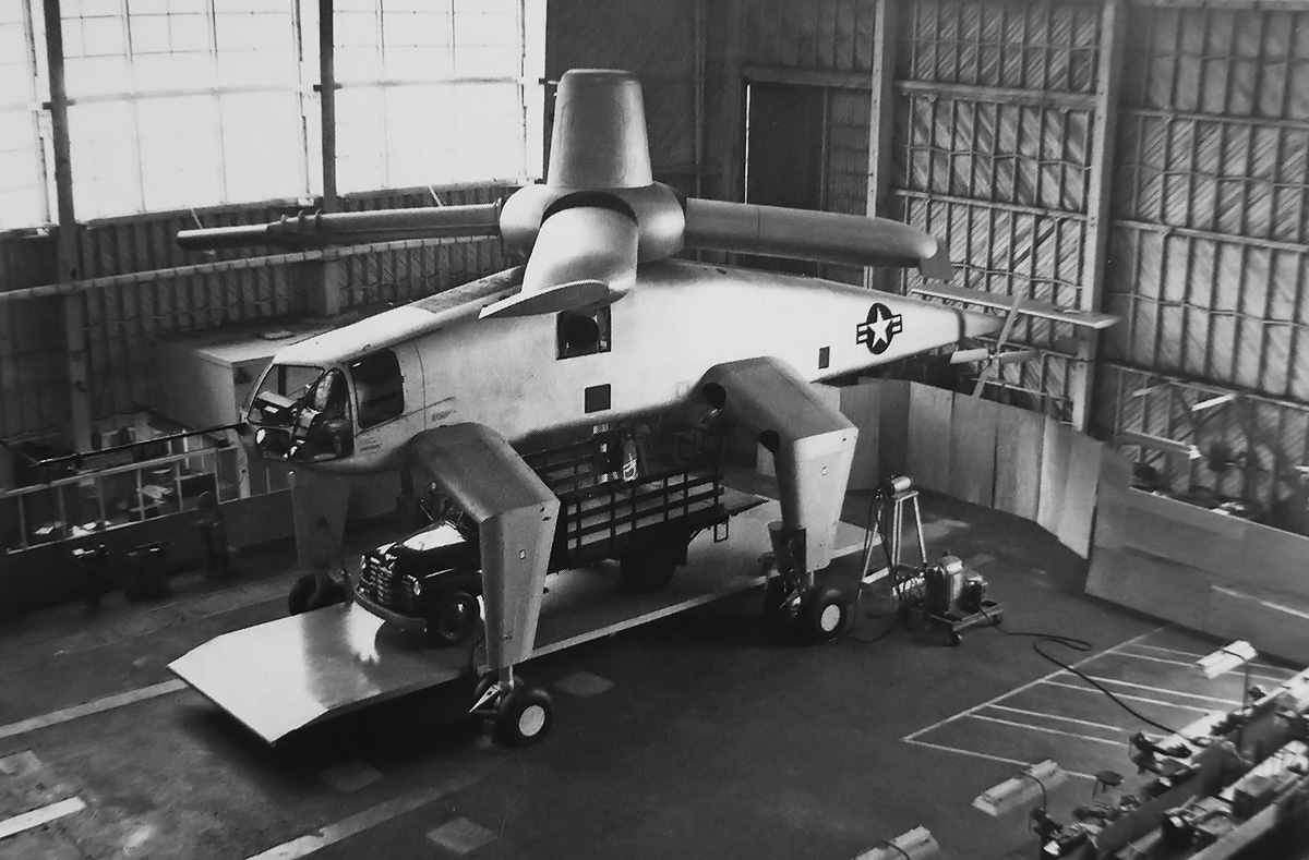
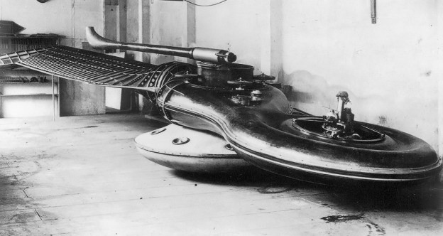
Full-scale mockup of the Hughes XH-28, which was planned as a larger, more capable heavy-lift helicopter than the XH-17. Vehicles could be driven onto the platform and secured, eliminating the need for the load to be suspended from the helicopter. (LIFE image via Google)

Sources:
McDonnell Douglas Aircraft since 1920: Volume II by René J. Francillon (1990)
Howard’s Whirlybirds by Donald J. Porter (2013)
Howard Hughes: An Airman, His Aircraft, and His Great Flights by Thomas Wildenberg and R.E.G. Davies (2006)
http://www.1000aircraftphotos.com/Contributions/VanTilborg/3138.htm

Sikorsky S-67 Blackhawk airbrakes

Sikorsky S-67 Blackhawk Attack Helicopter

By William Pearce

In the late 1960s, Sikorsky Aircraft had many helicopter models in production, but they had lost contracts to develop new helicopters. In 1966, the United States Army’s Advanced Aerial Fire Support System (AAFSS) contract was awarded to Lockheed, but their AH-56 Cheyenne attack helicopter ran into serious design issues. On 20 November 1969, Sikorsky initiated development of a new helicopter to be used primarily as a gunship, but it could also be used in other roles. This helicopter was designated S-67 Blackhawk, and its design and construction was self-funded by Sikorsky.

Sikorsky S-67 Blackhawk airbrakes

The Sikorsky S-67 Blackhawk was a very versatile helicopter that exhibited great performance, but it also had various shortcomings that the US Army could not overlook. The helicopter’s narrow fuselage and air brakes are illustrated in this image.

The Sikorsky S-67 Blackhawk was designed as a high-speed attack helicopter with a small wing to generate lift. The pilot and copilot/gunner sat in tandem in the helicopter’s cockpit, with the copilot in the front seat and the pilot in the rear seat. The pilot accessed the cockpit from the left side of the helicopter and the copilot from the right. The narrow, streamlined fuselage was only 3 ft 10 in (1.2 m) wide, which decreased the helicopter’s drag and increased its survivability by presenting a smaller target to enemy gunners. Behind the cockpit was a compartment that could be used for additional equipment or to transport personnel.

Sikorsky S-67 Blackhawk tail

This image shows the S-67’s original tail that did not have any rudders. Note the tail’s camber. Air brakes can be seen on the upper wing surfaces. The main gear had a 7 ft (2.1 m) track.

To cut expense and development time, the S-67 was designed to use the dynamic drive power system from a Sikorsky S-61/SH-3 Sea King. This included two 1,500 hp (1,119 kW) General Electric T58-GE-5 turboshaft engines and their drive, rotor, hydraulic, and electrical systems. The S-67’s five-blade rotors had 22 in (559 mm) of their tips swept back 20 degrees to delay compressibility effects, lower vibration, and reduce noise. The net effect was that the blades allowed the helicopter to achieve higher speeds. The main rotors also had a hub fairing, and their collective pitch control was modified to increase sensitivity and range.

The S-67’s main gear retracted into sponsons mounted on the fuselage sides. The helicopter’s thin wings extended from the sponsons. Each wing featured two hardpoints for weapons, auxiliary fuel tanks, or equipment. Each wing also had three air brakes: two that deployed along its upper surface and one that deployed along the lower surface. With the air brakes deployed, the helicopter slowed twice as fast as without the air brakes. In addition, the air brakes could be deployed during combat to offer unrivaled maneuverability. The S-67 was the first helicopter with air brakes.

A five-blade, 10 ft 7 in (3.2 m) diameter tail rotor was mounted to the left side of the S-67’s vertical fin. A lower fin with a non-retractable tailwheel extended below the helicopter’s tail. The large upper and lower fins were cambered to counteract the torque of the main rotor at speeds above 46 mph (74 km/h). This enabled controlled flight without the tail rotor as long as the S-67’s forward speed was in excess of 46 mph (74 km/h). If the tail rotor was lost, the helicopter could be flown back to base and landed like a conventional aircraft. The S-67 used an all-moving horizontal stabilizer that increased the helicopter’s maneuverability and decreased rotor stress.

Sikorsky S-67 Blackhawk landing

Note the angle of the all-moving horizontal stabilizer as the S-67 comes in for a landing. The landing gear was found to be insufficient for operating from unimproved locations. The helicopter’s double main wheels sunk into soft ground, and the gear doors only had 9.75 in (248 mm) of clearance.

With a 7,000 lb (3,175 kg) payload, the S-67 could accommodate a variety of armaments. A removable Emerson Electric Company TAT-140 turret mounted under the cockpit could carry a 7.62 mm minigun (M134), a 20 mm three-barrel rotary cannon (M197), a 30 mm single-barrel cannon (XM140), a 30 mm three-barrel rotary cannon (XM188), or a 40 mm grenade launcher (M129). The four underwing hardpoints could carry two drop tanks, up to 16 TOW missiles, or up to eight rocket pods. Each 2.75 in (70 mm) rocket pod contained 19 rockets, for a total of 152 rockets.

Sikorsky S-67 Blackhawk side

The S-67’s rudders can be seen in this image. One is on the upper fin below the tail rotor, and the other is on the lower fin. Pylons have been installed on the wings’ hardpoints, with drop tanks mounted to the inner stations. The turret is installed with a M197 three-barrel 20 mm cannon.

The S-67 had a wingspan of 27 ft 4 in (8.3 m) and a rotor diameter of 62 ft (18.9 m). The fuselage was 64 ft 2 in (19.6 m) long, and the helicopter’s total length including the rotor was 74 ft 1 in (22.6 m). The S-67’s mast height was 15 ft (4.6 m), and the top of the tail rotor was 16 ft 4 in (5.0 m). The helicopter’s top speed was 213 mph (343 km/h); maximum cruise speed was 201 mph (324 km/h), and normal cruise speed was 167 mph (269 km/h). The S-67 could climb at 2,000 fpm (10.2 m/s) and had a service ceiling of 20,000 ft (6,096 m). The helicopter could hover in ground effect up to 9,700 ft (2,957 m) and could hover without ground effect up to 6,500 ft (1,981 m). Maximum range on internal fuel was 325 miles (523 km), but its normal combat range was 220 miles (354 km). With external fuel tanks, range was extended to over 600 miles (966 km). The S-67 had an empty weight of 12,525 lb (5,681 kg), a normal weight of 18,500 lb (8,391 kg), and a maximum takeoff weight of 22,050 lb (10,002 kg).

Sikorsky S-67 Colonge Germany 1972

The S-67 seen in the same configuration as the previous image. The helicopter is over Cologne, Germany on its European and Middle Eastern tour in 1972.

Construction on the S-67 started on 15 February 1970 and proceeded rapidly. The helicopter made its first flight on 20 August 1970. Flight testing proved the S-67 to be very responsive, maneuverable, smooth, and quiet. The helicopter was able to perform rolls, loops, and split-S turns—although, only rolls to the right were made. On 14 December 1970, Sikorsky test pilots Kurt Cannon and Byron Graham in the S-67 established a new absolute speed record by averaging 216.841 mph (348.971 km/h) over a 3 km (1.86 mile) course. They then set a new record on 19 December 1970 by averaging 220.888 mph (355.485 km/h) on a 15–25 km (9.3–15.5 mile) course.

In 1971, the S-67 covered 3,500 miles (5,633 km) touring 12 US military bases. In addition to Sikorsky demonstration flights, the helicopter was flown on 147 demo flights with military personnel. The S-67 completed 155 rolls and 140 split-S turns during these flights.

Sikorsky-S-67-Blackhawk-fan-in-tail

A fan-in-fin anti-torque system was tested in the S-67. Note the rudders above and below the fan. No issues were encountered with the fan-in-fin, but the helicopter was converted back to a conventional tail rotor.

Between 25 May and 13 June 1972, the S-67 was flown 26 hours for a series of flight evaluations by the US Army. The helicopter was competing against the Bell 309/AH-1 KingCobra to replace the AH-56 Cheyenne, which had been cancelled. For the AAFSS role, the S-67 was designated AH-3, and Sikorsky’s proposal included adding an additional hardpoint to each wing, bringing the total number to six. This would enable the S-67 to carry up to 24 TOW missiles. While the S-67 was praised for its performance and most of its flight characteristics, the evaluation recorded a number of shortcomings. The Army did not award either Sikorsky or Bell a contract and decided to initiate a new Armed Attack Helicopter program, which eventually was won by the Hughes AH-64 Apache.

The S-67 underwent a number of modifications in late 1972. Rudders were added to the ventral and dorsal fins to increase yaw control. The compartment behind the cockpit was altered to enable the transport of six troops. Hardpoints were added to the wingtips for each to carry a Sidewinder missile. A hoist was added under the helicopter that allowed the S-67 to transport a 7,000 lb (3,175 kg) external load.

Sikorsky S-67 Blackhawk cockpit

After the fan-in-tail rotor tests, a small door was added on the left side of the fuselage to access the compartment behind the cockpit. Initially, access was gained (with some difficulty) via the door under the fuselage (seen above). The S-67 was then painted a light desert camouflage, and this was the helicopter’s final configuration.

With no interest from the US Armed Forces, Sikorsky offered the S-67 for export. In late 1972, the S-67 was taken on a two-month tour of Europe and the Middle East. More than 7,500 miles (12,070 km) were covered, and the helicopter was flown for 136 hours. Despite interest from Israel, no orders were placed. Sikorsky then modified the S-67 to test a fan-in-fin tail rotor installation. A 4 ft 8 in (2.6 m), seven-blade rotor was installed in the modified tail. The helicopter underwent flight tests, including a dive at 230 mph (370 km/h). After the tests in 1974, the S-67’s tail was converted back to its previous configuration (with rudders), and a door to access the rear compartment was installed in the helicopter’s left side. The S-67 was then painted a light desert camouflage. The data from the fan-in-fin test was used for the Sikorsky H-76 fantail demonstrator, which tested the tail configuration later used in the Boeing-Sikorsky RAH-66 Comanche.

Sikorsky S-67 Blackhawk inverted

The S-67 made hundreds of rolls in its lifetime, but they were always to the right. The square in the fuselage above the wing is the window in the new rear compartment access door. What appear to be two rectangular windows can be seen father aft. Note the helicopter’s rudders and deployed air brakes.

On 26 August 1974, the S-67 arrived in the United Kingdom to start another European tour. On 1 September 1974, the S-67 was destroyed after failing to recover from a second roll during a practice session for the upcoming Farnborough Air Show. The copilot, Stu Craig, was killed in the crash, and the pilot, Kurt Cannon, died from his injuries nine days later. The accident was caused by the second roll being initiated in a less than ideal configuration combined with low altitude. However, the accident investigators believed that the crash was survivable had the helicopter been fitted with five-point harnesses rather than four-point harnesses. The S-67 had accumulated 598.7 hours at the time of the crash.

With the prototype destroyed and no interest from the US military, Sikorsky decided to end the S-67 Blackhawk program. Its swept-tip rotor blades were developed into those used on the Sikorsky S-70/UH-60 Black Hawk (the name similarity is a coincidence) and other helicopters. The S-67’s speed record stood for eight years until it was broken on 21 September 1978 by the Soviet Mil A-10 (modified Mi-24B) at 228.9 mph (368.4 km/h).

Sikorsky S-67 Blackhawk crash

The S-67 tries to recover from a roll a split second before it impacts the ground. The helicopter’s low altitude left no room to recover from the roll, which was rushed and initiated in a flawed manner. The crash would ultimately kill the pilot and copilot and end the S-67 program.

Sources:
http://www.sikorskyarchives.com/S-67%20BLACKHAWK.php
https://en.wikipedia.org/wiki/Sikorsky_S-67_Blackhawk
http://www.aviastar.org/helicopters_eng/sik_s-67.php
http://1000aircraftphotos.com/Contributions/Visschedijk/6269.htm
– “Blackhawk’s Last Flight” Aeroplane Monthly (June 1976)
Attack Helicopter Evaluation, Blackhawk S-67 Helicopter by George M. Yamakawa, et al (July 1972)

CTA - ITA Heliconair Convertiplano drawing

CTA / ITA Heliconair HC-I Convertiplano

By William Pearce

In 1923, Henrich Focke partnered with Georg Wulf to create Focke-Wulf Flugzeugbau (Aircraft Company) in Bremen, Germany. Focke became fascinated with helicopters and other rotorcraft in the 1930s. This interest led to what is considered the first practical helicopter, the Focke-Wulf Fw 61, which first flew in 1936. That same year, Focke was ousted from Focke-Wulf due to internal disagreements about allocating company resources. In 1937, Focke partnered with Gerd Achgelis, the Fw 61’s lead designer, to create Focke-Achgelis & Co in Hoykenkamp, Germany. The new company would focus on helicopter and rotorcraft designs.

CTA - ITA Convertiplano side

The Heliconair HC-Ib Convertiplano sits nearly finished in a hangar. The slit behind the cockpit was the intake for air used to cool the fuselage-mounted R-3350 engine. The scoop on the upper fuselage brought air to the engine’s carburetor. Note the Spitfire wings and main gear.

In 1941, the RLM (Reichsluftfahrtministerium or Germany Air Ministry) requested that Focke-Achgelis design a fighter capable of vertical takeoff and landing (VTOL). Focke-Achgelis responded with the Fa 269 design, which was a tiltrotor convertiplane. The Fa 269 had two rotors—one placed near the tip of each wing in a pusher configuration. The rotors were powered by an engine housed in the aircraft’s fuselage via extension shafts and gearboxes. The rotors and extension shafts leading from the right-angle gearboxes mounted in the aircraft’s wings rotated down to “push” the Fa 269 into the air, achieving vertical flight. Once airborne, the rotors and shafts would slowly translate back into the wing to propel the aircraft forward, allowing the aircraft’s wings to provide lift. The project moved forward until 1944, when much of the developmental work, including models, a mock-up, and gearboxes, was destroyed in an Allied bombing raid.

CTA - ITA Heliconair Convertiplano

Drawings of how the completed HC-Ib was anticipated to look reveal a pretty compact aircraft, considering the engine installation and associated shafting. The R-3350 engine took up the space intended for a passenger compartment in the Double Mamba-powered HC-I. The Double Mamba would have been installed aft of the passenger compartment.

Immediately following World War II, Germany was prohibited from designing and manufacturing aircraft. Post war, Focke assisted with helicopter development in France and worked for a car company in Germany. He also spent some time in the Netherlands, where he began to design a VTOL aircraft that was capable of relatively high speeds. In 1952, Focke was recruited by the CTA (Centro Técnico de Aeronáutica or Technical Center of Aeronautics) to work in the recently established ITA (Instituto Técnico de Aeronáutica or Technical Institute of Aeronautics). The ITA was the first of four institutes formed by the CTA, all of which were located in São José dos Campos, Brazil. Brazil was working on building an aeronautics and aerospace industry and was actively recruiting German engineers. In addition to Focke, many of his associates and former co-workers were also recruited.

The CTA was impressed with Focke’s VTOL aircraft design and approved its construction. The CTA believed that the aircraft’s capabilities would allow it to reach remote parts of Brazil. Focke set to work on the aircraft—a tiltrotor convertiplane design that was partially inspired by the Fa 269. The aircraft was known as the Heliconair HC-I Convertiplano. Its fuselage and wings were fairly conventional for an aircraft, but it had of two sets of rotors. One pair of rotors was placed near the nose of the aircraft, and the other pair was placed between the wings and tail. All of the rotors were of a tractor configuration and rotated up for vertical flight. The HC-I accommodated two pilots in the cockpit and four passengers in the fuselage. The aircraft’s estimated performance included a top speed of 311 mph (500 km/h) and a range of 943 miles (1,517 km).

CTA - ITA Convertiplano engine test rig

The test rig for the engine, transmission, gearboxes, shafts, right-angle drives, and rotors illustrates the complexity of the HC-Ib’s power system. The R-3350 engine did not have any Power Recovery Turbines, which means it was not a Turbo Compound engine.

To save time and money, the decision was made to build the HC-I using the wings and the horizontal stabilizer from a Supermarine Spitfire. A Spitfire XIVe (RM874) was purchased without its Rolls-Royce Griffon 65 engine from Britain by the Brazilian Air Attaché on 19 December 1952. A new fuselage was built to house a 3,000 hp (2,237 kW) Armstrong Siddeley Double Mamba turboprop engine behind the passenger compartment. However, Armstrong Siddeley and the British did not want one of their new, advanced engines being used in such a radical project and declined selling a Double Mamba engine to Brazil.

Focke and the Convertiplano team changed the HC-I’s design to accommodate a 2,200 hp (1,641 kW) Wright R-3350 radial engine and redesignated the aircraft HC-Ib. The R-3350 was larger and heavier than the Double Mamba, and it produced less power. Some sources state a Turbo Compound R-3350-DA3 (3,250 hp / 2,424 kW) was used, but images show that there are no Power Recovery Turbines on the engine installed in a test rig. Extensive modifications to the aircraft’s fuselage were required to accommodate the air-cooled engine. The passenger compartment was omitted, and the R-3350 was installed in the middle of the fuselage. An annular slit behind the cockpit was added to bring in cooling air for the engine. After passing through the engine’s cylinders, the air exited via a jet-like duct at the rear of the aircraft. The Spitfire’s landing gear was strengthened to compensate for the R-3350’s weight.

CTA - ITA Convertiplano components

The HC-Ib sits in the background with the front and rear gearboxes and rotor drives in the foreground. The rotor blades, the only surviving component of the Convertiplano project, are not seen in the image. Note the opening at the rear of the fuselage, which was the exit for engine cooling air.

A gearbox transmission mounted to the front of the R-3350 split the engine’s power to two shafts. The front shaft extended from the engine to the front gearbox. The front gearbox had shafts that extended to the left and right. These shafts led to right-angle gearboxes that powered the front rotors. Power delivery for the rear rotors was more complex. A shaft extended vertically from the transmission on the front of the engine and met a right-angle gearbox positioned directly above the engine. From the right-angle gearbox, a shaft extended back to the rear gearbox. The rear gearbox had the same shafts and right-angle drives for the rear rotors as the front gearbox. The transmission and gearboxes were designed by Willi Bussmann and built by BMW in Germany. Bussmann was a former BMW employee and had worked with Focke on several Focke-Achgelis projects.

Each rotor consisted of three blades. The blades were built in Sweden and made of a steel frame that was covered with wood. The blades’ pitch automatically adjusted and had collective and cyclic control. The rotors were counter-rotating, with the right rotors turning counterclockwise and the left rotors turning clockwise. The HC-Ib had a 37 ft 6 in (11.42 m) wingspan and was 35 ft 3 in (10.74 m) long.

CTA - ITA Convertiplano engine hoist

Given the state of the aircraft and the surrounding unchecked growth of vegetation, it can be assumed this image is of the R-3350 engine being removed sometime after the HC-Ib project was cancelled. The image does give proof that the engine was installed in the airframe at one point.

A rig was built, and tests of the engine, gearboxes, shafts, right-angle drives, and rotors began in late 1953. However, vibrations from the radial engine caused some issues that took time to resolve. The HC-Ib airframe was almost completely constructed and had its engine installed when the project was cancelled in 1955. The aircraft was more expensive than anticipated, and interest in the HC-1b had steadily declined after the switch to the R-3350 engine. To make matters worse, many of the Germans returned to Europe or went to the United States as their contracts with the CTA expired. Some Germans did stay and ultimately became part of Embraer. After the project was cancelled, the HC-Ib Convertiplano was left to rot in outside storage for some time and was eventually scrapped in the 1970s. There are some reports that the rotor blades are the only part of the aircraft that survived.

A follow up Convertiplano project was considered. Designated HC-II, the aircraft would be powered by four 1,400 hp General Electric T58 turboshaft engines and reincorporate a four to six passenger cabin. The HC-II never progressed beyond the initial design phase.

CTA - ITA Convertiplano HC-II

The C-II Convertiplano had a GE T58 engine mounted directly to each of its four rotors. Otherwise, it retained the configuration of the original HC-I.

Sources:
Axis Aircraft in Latin America by Amaru Tincopa and Santiago Rivas (2016)
– “Uma Breve História das Atividades do Prof. Focke no Brasil” by Joseph Kovacs, ABCM Engenharia Volume 9 Número 2 (April–September 2003)
http://www.internationalresinmodellers.com/articles_15_cta_heliconair_hc-i_-ii_convertiplano
http://aeromagazine.uol.com.br/artigo/convertiplano-o-pioneiro-esquecido_491.html
https://en.wikipedia.org/wiki/Henrich_Focke
https://en.wikipedia.org/wiki/Focke-Wulf
http://allspitfirepilots.org/aircraft/RM874
http://www.secretprojects.co.uk/forum/index.php?topic=25141.0
http://forum.keypublishing.com/showthread.php?24794-Mark12-s-Quiz&s=17aba5b94d69d4e1642b3d04aefcf85c

Dorand Gyroplane G20 complete 1947

Dorand Gyroplane G.20 (G.II)

By William Pearce

Since the early 1900s, Frenchman Louis Bréguet was interested in rotorcraft. But, the technical challenges of controlling such machines and the lack of suitable power plants led Bréguet to pursue the development of aircraft instead. In the late 1920s, Bréguet’s interest returned to rotorcraft, and he created the Syndicat d’Etudes de Gyroplane (Syndicate for Gyroplane Studies) in 1931 with René Dorand as its Technical Director. The syndicate produced a successful experimental helicopter known as the Bréguet-Dorand Gyroplane Laboratoire, which first flew on 26 June 1935. The Gyroplane Laboratoire used two sets of two-blade, coaxial, contra-rotating rotors. No tail rotor was used, as the contra-rotating rotors cancelled out the torque reaction of the blades. The helicopter set a number of speed and distance records.

Dorand Gyroplane G20

A drawing of the Dorand Gyroplane G.20 in what appears to be its final form. The drawing illustrates one of the two inverted Renault inline-six engines and the two-person cockpit.

In 1938, Dorand amicably parted with Bréguet and established the Société Française du Gyroplane (French Gyroplane Company), abbreviated SFG or just Gyroplane for short. The French Navy (Marine Nationale) commissioned the SFG to design a combat helicopter for costal defense and anti-submarine warfare. Dorand designed the new machine, and its layout was similar to that of the Gyroplane Laboratoire. The new helicopter was designated the Gyroplane G.20, but it is also known as the Dorand G.20 or the Dorand G.II.

The G.20 had a cigar-shaped fuselage of all metal construction. A butterfly tail was attached to the extreme end of the fuselage, and the tail’s control surfaces were fabric-covered. The streamlined nose of the G.20 was covered with plexiglass panels. The pilot sat in the nose of the helicopter with either one or two crewmen behind.

Dorand Gyroplane G20 org drawing

A drawing of the original Dorand G.20 with its three-man crew and rotor mast gunner turret. Note the side-mounted machine gun (pointed toward the rear) and the bomb load. An inverted, inline, six-cylinder, Renault engine is also visible. The rotors on the left are shown in their normal position, while the rotors on the right are at their maximum upward deflection.

At the center of the helicopter were two three-blade, coaxial, contra-rotating rotors. The distance between the rotors was 2 ft 2 in (0.65 m), and the lower rotor had a smaller diameter than the top rotor to ensure the blades would not collide. The upper rotor had a diameter of 50 ft 6 in (15.4 m), and the lower rotor’s diameter was 42 ft 8 in (13.0 m)—7 ft 10 in (2.4 m) smaller.  The magnesium blades were made of two parts: a box forming the leading edge and a separate trailing edge. As with the Gyroplane Laboratoire, articulation of the blades allowed for both cyclic and collective pitch control, and no tail rotor was used.

The rotor blades were powered by two Renault 6Q-04 engines. The 6Q was an air-cooled, inverted, inline, six-cylinder engine with a 4.72 in (120 mm) bore and a 5.51 in (140 mm) stroke. The engine’s total displacement was 580 cu in (9.5 L). The 6Q-04 was supercharged and produced 240 hp (179 kW) at 2,500 rpm up to 13,123 ft (4,000 m). A special gearbox transferred power from the engines to the rotors. If one of the engines were to fail, that engine would be automatically disconnected, and the remaining engine would power both sets of rotors.

Dorand Gyroplane G20 org drw

This top view drawing of the G.20 clearly shows the side-mounted machine gun and engine placement. The outline of bombs can be seen under the rotor mast.

The G.20 was supported by two main wheels and a tailwheel. The tail and main wheels all retracted backward into the fuselage and were fully enclosed by gear doors. The space in the fuselage between the main gear and below the rotors was for either bombs or a depth charge. In addition, Dorand’s original design included a machine gun mounted on the helicopter’s side and a turret mounted on top of the rotor mast—with the guns operated by separate crewmen. The mast turret was unique in that it was essentially a hollow drum to which the rotors were attached. A gunner occupied the center of the drum and had a 360 degree field of fire. However, all armament and the rotor turret were omitted from the G.20. Most sources list the completed G.20 as having a two-person crew consisting of a pilot and copilot. The helicopter’s final role was defined as observation, liaison, and mail-carrying.

The G.20’s fuselage had a length of 36 ft 4 in (11.08 m) and a height of 10 ft 3 in (3.13 m). The helicopter’s empty weight was 3,086 lb (1,400 kg); normal operating weight was 5,512 lb (2,500 kg), and maximum weight was 6,614 lb (3,000 kg). The G.20’s hover ceiling was 9,843 ft (3,000 m), and it had a maximum ceiling of 16,404 ft (5,000 m). The helicopter’s range was 497 mi (800 km). Its cruise speed was 103 mph (165 km/h), and its maximum speed was 155 mph (250 km/h) at 8,202 ft (2,500 m).

Dorand Gyroplane G20 complete 1947

The completed Dorand G.20 after World War II. With the machine guns no longer part of the design, nothing is left to interrupt the helicopter’s sleek lines. Note the long gear door.

Construction of the G.20 started in Guethary in south-western France, near Spain. When the German Army invaded France in 1940, the helicopter was moved to Chambéry in south-eastern France, near Italy, and construction resumed. By this time, Marcel Vuillerme had taken over the project from Dorand. As the Germans pushed into southern France, the G.20 was discovered. The Germans showed little interest in the helicopter and allowed its construction to continue, albeit slowly.

The G.20 was completed in 1947 and underwent ground tests. It was the French officials who now showed little interest in the project, and funding was not forthcoming. Its estimated performance was optimistic, and while its streamlined appearance and retractable gear appeared futuristic, in many ways the G.20 was obsolete after war-time helicopter developments made in the United States and Germany. Further development and testing of the G.20 was abandoned, and the helicopter never flew. However, the SFG continued to develop helicopters for a time. The SFG worked with Bréguet to construct a four-passenger helicopter, the G.11E, which first flew in 1949. The G.111 was a follow-on project that first flew in 1951. The SFG went out of business in 1952.

Breguet G11E

The G.11E was designed by SFG after the G.20. It was built by Bréguet and powered by a 9-cylinder Potez 9E radial engine. It first flew in 1949 and had a layout similar to the G.20.

Sources:
Les Avions Breguet 1940/1971 by Jean Cuny and Pierre Leyvastre (1973)
René Dorand: 50 Ans de Giraviation by Pierre Boyer (1992)
http://en.wikipedia.org/wiki/Breguet-Dorand_Gyroplane_Laboratoire
http://en.wikipedia.org/wiki/Breguet_G.11E

Brennan Helicopter Tethered

Brennan Helicopter

By William Pearce

Born in 1852, Irish inventor Louis Philip Brennan had contemplated the concept of a flying machine (helicopter) as early as 1884. However, the art and science of aeronautics was very much in its infancy, and there was much to be learned. Even if the knowledge had existed, there were no suitable power plants light enough and powerful enough to propel man aloft in any machine, much less in a helicopter.

Brennan Helicopter early

The Brennan Helicopter with its inventor Louis Brennan standing before it and engineer/pilot Robert Graham in the pilot’s seat. This early tethered test photo shows the machine before its fuselage was completed.

In the mid-1910s, technology began to catch up with Brennan’s idea for a helicopter, and the British Ministry of Munitions backed Brennan’s experimental helicopter project on 29 June 1916. Under strict secrecy, design work progressed slowly, and it was not until 1919 that construction actually began at the Royal Aircraft Establishment at Farnborough. The helicopter project was encouraged and supported by Winston Churchill, who transitioned from Minister of Munitions to Minister of Air at that time. Engineer Robert Graham joined Brennan’s team in 1920.

The helicopter was constructed with a small fuselage (or pilot’s car) supported on the ground by four outrigger legs. The fuselage was equipped with a small rudder, and the fuel tank was under the pilot’s seat. Above the fuselage were the rotor blades and engine attached to a pyramid-shaped, steel supporting frame. The two wide chord rotor blades themselves were not powered; their rotation was achieved by a small four-blade propeller positioned at the tip of each rotor blade. This configuration provided virtually torqueless rotation of the rotor blades. The blades had a steel and wood frame and were covered in doped fabric. Each rotor blade was supported by a hollow tube (spar) through which the drive shaft ran to the tip propeller. The pilot could articulate the hollow tubes to change the incidence of the rotor blades. Each blade also had an aileron to further enhance the helicopter’s control.

Brennan Helicopter Patent

A drawing from Brennan’s “Improvements relating to Aerial Navigation” patent submitted in 1916. Note the small propellers (marked “n”) that were to be used for control. These propellers and their complicated drive systems were omitted from the actual helicopter.

The controls were pneumatic, and the base cross tubes of the pyramid structure were enlarged to act as air reservoirs. Pressurized air was provided by an engine-driven compressor. The entire pyramid structure rotated when the helicopter was under power. The structure was attached to the fuselage via a universal joint. This joint was hollow, and flight controls and fuel lines passed through it.

The tip propellers were geared to the engine via shafts and right angle gearboxes. Originally, a 150 hp (112 kW) Bentley BR 1 rotary engine was used, but a 230 hp (172 kW) Bentley BR 2 rotary engine was substituted because more power was needed. The nine-cylinder BR 2 engine had a 5.5 in (140 mm) bore and a 7.1 in (180 mm) stroke, resulting in a total displacement of 1,522 cu in (24.9 L). The rotary engine was positioned horizontally and revolved the same direction as the rotor blades (but faster). The helicopter blades had a 61 ft (18.6 m) diameter and a 6 ft (1.8 m) cord and rotated between 50 and 60 rpm. The total blade area was 240 sq ft (22.3 sq m). Brennan’s helicopter weighed 2,765 lb (1,254 kg).

Brennan Helicopter Tethered

The Brennan Helicopter tethered in a hangar at Farnborough. Brennan is standing next to the machine with Graham occupying the cockpit. The fuselage has been completed and its rudder is visible. Note the cross braces of the pyramidal structure that acted as air reservoirs and the aileron on the rotor. The axillary rotors have not been added.

An attempt was made to begin Engine-powered spin tests of the rotor blades on 4 November 1921. The helicopter did not have its own starter at the time. A Hucks starter was used, engaging one of the tip propellers. The rotor blades were braced to prevent their movement. However, once the engine was started, the brace moved and was hit by a propeller. All testing stopped until the damage could be repaired.

By 7 December, Brennan had designed and fitted his helicopter with a mechanical starter. The helicopter was rigged for tethered tests inside a balloon hangar at Farnborough. Brennan decided that since Graham had complete knowledge of the machine, he should be the one to fly it. The first tethered flight occurred on 22 December. Although the Air Ministry assigned pilots Paul “George” Bulman and Cecil Bouchier to the project, Graham made about 90% of the helicopter flights.

Brennan Helicopter complete

Brennan’s helicopter ready for outside tests at Farnborough. Note the square-shaped auxiliary rotors.

The tethered tests showed the helicopter to be underpowered, and it was at this time that the BR 2 engine was installed. With this engine, the helicopter could lift the pilot, four men, and an hour’s worth of fuel. However, the 60 ft (18.2 m) tall hangar provided a limited test environment, and the helicopter’s ascents did not top 20 ft (6.1 m). Stability tests, while still in the hangar, showed that directional control was not sufficient, and use of the ailerons hindered the helicopter’s control compared to blade articulation alone. A solution to the control deficiencies was to add additional rotor blades. Ideally, two full blades would have been added, but for simplicity, cost, weight, and speed of conversion, two small auxiliary blades were added. The auxiliary blades increased the lifting surface area by 60 sq ft (5.6 sq m), bringing the total to 300 sq ft (27.9 sq m).

On 16 May 1924, the helicopter was tested out of the hangar for the first time. Initially, the helicopter was tethered, but free-flight tests commenced once confidence in the helicopter was gained. Since space was limited, the helicopter’s height was kept under 10 ft (3 m). A number of flights were made, some of which were flown by Brennan. Complete control was still a concern, and Brennan had designed a gyro to automate minor control adjustments and stabilize the helicopter. However, the Air Ministry wanted proof that unassisted control was achievable before any type of automatic control was added. It was estimated the helicopter could achieve a forward speed of 20 mph (32 km/h) and an altitude of 600 ft (183 m).

Brennan Helicopter flight

The helicopter in low flight and perhaps lacking a little control. For all the flights, it was never flown higher than 10 ft (3 m).

On 2 October 1925, the helicopter was being demonstrated before a number of officials when partial control was lost. Close to landing, the pyramid structure of the helicopter tilted and the blades struck the ground. While the blades were damaged, the propellers and gearboxes at their tips were destroyed. Although a definitive cause was not found, it was believed that contaminants had been introduced into the air system and caused a valve to malfunction.

At this time, some in the Air Ministry felt there was no future for the helicopter and were not interested in continuing with Brennan’s experiment. Also, Juan de la Cierva’s Autogiro was showing some promise without all the complications of the helicopter. Subsequently, the decision was made to terminate the Brennan Helicopter project and investigate the Autogiro. Brennan was notified of the decision on 29 January 1926. He felt that cancelling the work on his helicopter was a mistake and that the Autogiro would never do everything a helicopter could. Brennan predicted helicopters would eventually provide unparalleled service to the world.

Even though most components were undamaged, Brennan’s helicopter was never repaired. Louis Brennan died in 1932, about five years before other pioneers began to demonstrate the unique abilities of the helicopter. The Brennan Helicopter made over 70 free flights, and it was the first helicopter to fly in the United Kingdom.

Brennan Helicopter flight front

A good photo of the Brennan Helicopter in steady flight. Note that the aileron is at a slightly different angle than that of the rotor blade.

Sources:
– “Brennan—his helicopter and other inventions” by Robert Graham The Aeronautical Journal (February 1973)
Louis Brennan Inventor Extraordinaire by Norman Tomlinson (1980)
W O Bentley Rotary Aero Engines by Dr. Tom Dine (2014)
– “Improvements relating to Aerial Navigation” G.B. patent 281,735 by Louis Brennan (granted 10 December 1918)

PKZ 2 engines 3

Petróczy-Kármán-Žurovec PKZ 2 Helicopter

By William Pearce

In 1916, Major Stephan Petróczy von Petrócz of the Austro-Hungarian Army envisioned replacing hydrogen-filled observation balloons with tethered helicopters. These helicopters would have been used as static observation platforms. Compared to hydrogen balloons, the helicopters’ were much less likely to catch fire, presented a smaller target for the enemy, increased operational readiness, required fewer ground and support crew, and eliminated the need for hydrogen generating equipment.

PKZ 2 with basket 3

Follow-on to the PKZ 1, the Petróczy-Kármán-Žurovec PKZ 2 is shown here with the observation basket attached above the rotors. This image was taken after the PKZ 2 was modified in May 1918 and the 120 hp (89 kW) La Rhône engines are installed.

To achieve his goal, Petróczy, along with Oberleutnant Dr. Theodor von Kármán and Ingenieurleutnant Wilhelm Žurovec, conceived the Schraubenfesselflieger (S.F.F) mit Elektromotor (captive helicopter with electric motor). This machine is now commonly refered to as the Petróczy-Kármán-Žurovec 1 (PKZ 1) helicopter. Built in 1917 and primarily designed by von Kármán and Žurovec, the PKZ 1 consisted of a rectangular frame with an observation basket in the middle. On each side of the basket were two lift rotors. All four rotors were powered by a single 190 hp (142 kW) Austro-Daimler electric motor.

The PKZ 1 was flight tested and was able to lift three men to a tethered height of 20 in (50 cm).  However, the electric motor generated 50 hp (37 kW) less than anticipated, and on the fourth flight, the straining motor gave out. Because of the scarcity of high-grade electrical copper and quality insulation, Daimler was not able to repair the motor. In addition, the PKZ 2, which was originally known as the S.F.F. mit Benzinmotor (captive helicopter with petrol engine), was nearing completion. No further work was done on the PKZ 1.

PKZ 2 engines 3

PKZ 2 rotary engine arrangement with the 100 hp (75 kW) Gnomes installed.

The PKZ 2 helicopter (for which he received German patent 347,578) was designed solely by Wilhelm Žurovec. The PKZ 2 was privately funded by the Hungarian Bank and the iron foundry / steel fabrication firm of Dr. Lipták & Co AG, who built the machine. The PKZ 2 utilized two two-blade contra-rotating rotors to cancel out torque and provide lift. The rotors, made of high-quality mahogany, were 19 ft 8 in (6.0 m) in diameter and were rotated at 600 rpm by three 100 hp (75 kW) Gnome rotary engines. A removable observation basket sat atop the rotors.

The craft had three outrigger legs; each supported one engine. All engines were connected to the rotors via a common gearbox. The PKZ 2 was supported by a central air cushion and three additional air cushions; one on each outrigger leg. These air cushions were filled by an air pump driven from the rotor drive. Attached to each outrigger was a tethering cable that was connected to the ground and controlled by an electric winch. With one hour of fuel, The PKZ 2 weighed 2,645 lb (1,200 kg).

PKZ 2 Takeoff2

PKZ 2 shown just off the ground and without the observation basket on 5 April 1918, powered by the 100 hp (75 kW) Gnome engines.

Tethered and unmanned, the PKZ 2 was test flown on 2 April 1918. After several flights, including one that lasted about an hour, tests were suspended on 5 April because of insufficient power from the Gnome engines. The engines were replaced by 120 hp (89 kW) La Rhône engine (that were captured and rebuilt) and, with a few additional modifications, tethered and unmanned flight tests resumed on May 17th. With the new engines and calm winds, an altitude of 165 ft (50 m) was achieved, and the PKZ 2 could lift 330–440 lb (150–200 kg). The craft would lose lift at higher altitudes, but the PKZ 2 was kept under control as long as tension remained on the tethering cables.

PKZ 2 hover 2

PKZ 2 in a tethered high hover with power provided by the 120 hp (89 kW) La Rhône engines on 10 June 1918.

On 10 June 1918 the PKZ 2 was demonstrated for high ranking members of the military. A flight was made with the observation basket in place, but the engines were not running well and the craft became unstable. The basket was removed and another flight attempted. The wind had picked up, and as the PKZ 2 hovered at 40 ft (12 m) tethered to the ground, the craft began to rock. The overheating engines lost power, and the tether winch crew could no longer maintain control. The PKZ 2 crashed from a height of 6.5 ft (2.0 m), severely damaging the airframe and completely destroying the rotors.

Realizing the technical problems could not be overcome quickly, the government cancelled the project on 21 June 1918. However, Žurovec pressed on and began to design an individual cylinder water jacket to water-cool the rotary engines. The craft was being rebuilt to resume flight tests in November 1918 when the end of the war and revolution caused all development to cease. The PKZ 2 made over 15 tests flights, but it is doubtful any were manned.

PKZ 2 Crash 2

Remains of the PKZ 2 after it crashed on 10 June 1918.

Sources:
Austro-Hungarian Army Aircraft of World War One by Grosz, Haddow, and Schiemer (2002)
Recent Developments in European Helicopters NACA Technical Note No. 47 by von Kármán (1921) pdf
http://forumeerstewereldoorlog.nl/wiki/index.php/PKZ_2_Schraubenflieger
http://www.valka.cz/clanek_13499.html
– Comment by Kees Kort

Papin-Rouilly Gyroptere (Gyropter)

By William Pearce

The Papin-Rouilly Gyroptere as depicted on the cover of the September 1922 edition of Popular Science.

The Gyroptere was designed in France from 1911-1914 by Alphonse Papin and Didier Rouilly. Their monocopter was based on the sycamore seed; a single blade extends from the seed to spin the seed and slow its descent as it falls. Though unsuccessful, the machine was the first air-jet helicopter. Papin and Rouilly obtained French patents 440,593 and 440,594 for their invention and later obtained U.S. patent 1,133,660 in 1915 (filed in 1912).

Construction of Papin and Rouilly’s Gyroptere began in February 1914 and was completed in June of the same year. The prototype was named Chrysalis (Chrysalide). Constructed of molded wood, the Gyroptere was well built with compound curves and a smooth sweep of its single, long, airfoil-shaped blade. The fabric-covered blade was hollow and approximately 19.5 ft (5.9 m) long and 4.4 ft (1.33 m) wide, giving it an area of 130 sq ft (12 sq m). The blade was counterbalanced by an 80 hp (60 kW), nine-cylinder Le Rhone rotary engine. The pilot occupied a nacelle between the blade and engine. The bottom of the nacelle included a structure to support the machine while it was on the ground or act as a float when on water.

The Le Rhone engine was started with a pulley system. The engine, turning at 1,200 rpm, drove a fan that produced an output of just over 250 cu ft (7 cu m) of air per second. The air, along with the engine’s hot exhaust for thermal expansion, was directed through the length of the blade and exited the blade’s tip through a nozzle on the trailing edge at 330 ft/s (100 m/s). This jet of air would turn the blade, and the gyroscopic force of the motor would lift the blade into a positive angle of attack. The nacelle that carried the pilot was centered on the axis of rotation. The nacelle was mounted on ball-bearings and was centered against four horizontal rollers. The entire machine weighed 1,100 lb (500 kg), which was 220 lb (100 kg) more than originally planned.

This image offers a good view of the Gyroptere. The blade does not have its covering, the float and directional control tube can clearly be seen in the center nacelle, and the Le Rhone engine in its fan housing is on the right.

The pilot controlled the Gyroptere through the use of two foot pedals: one pedal opened a valve to admit air to the blade; and the second pedal allowed air into an L-shaped tube above the craft that served as a rudder for directional control. The L-shaped tube was directed by the pilot; its discharge provided forward thrust, steering, and stabilized the center drum to prevent it from spinning with the blade. A switch in the nacelle allowed the pilot to engaged or disengaged the engine.

This view highlights the air-jet nozzle on the trailing edge of the blade, which can be seen on the left.

The outbreak of World War I delayed testing until 31 March 1915. During tests on Lake Cercey (Reservoir de Cercey), near Pouilly-en-Auxois, France, the craft achieved a rotor speed of only 47 rpm, well below the 60 rpm calculated as necessary for liftoff. Even so, the machine was wildly out of balance, and the blade repeatedly contacted the water, damaging itself and shaking up the pilot. In addition, the Le Rhone engine used was not powerful enough; the Gyroptere had been designed to use a 100 hp (75 kW) engine which could not be obtained.

A military commission observing the test determined that such a machine could not aid the war effort and halted further evaluation. The Gyroptere remained at Lake Cercey until it was sold for scrap in 1919.

The completed Gyroptere awaiting tests on Lake Cercey on 31 March 1915.

Sources:
French Aircraft of the First World War by Davilla and Soltan (1997)
– “Helicopter” U.S. Patent 1,133,660 by Papin and Rouilly (1915) pdf
http://fr.wikipedia.org/wiki/Gyropt%C3%A8re
http://en.wikipedia.org/wiki/Monocopter
http://flyingmachines.ru/Site2/Crafts/Craft29386.htm
– “Will This ‘Whirling Leaf’ Flying Machine Solve Greatest Problem in Aviation?Popular Science (September 1922)

Sikorsky S-56 (CH-37 Mojave/Deuce) Helicopter

By William Pearce

At the time of its introduction, the Sikorsky S-56 was the largest and fastest military helicopter in the Western world. In 1956, the helicopter set two height-with-payload world records and one world speed record. The S-56 was also Sikorsky’s first multi-engined helicopter and remains the largest piston-engined helicopter ever built.

CH-37B Mojave in flight. The screen on the side of the engine nacelle to maximize engine cooling is visible.

The S-56 was powered by two Pratt & Whitney R-2800 air-cooled radial engines with a takeoff rating of 2,100 hp (1,566 kW) and a cruise rating of 1,900 hp (1,417 kW). R-2800-50 engines were initially used, but late production aircraft used R-2800-54 engines, which had upgraded magnetos and additional mounting studs. The engines were connected to the main rotor’s transmission via a hydro-mechanical clutch. This clutch allowed the engines to run independently from the main rotor for starting or in the event of an engine failure. Power for the tail rotor was taken off the main transmission.

Unlike most heavy lift helicopters, the engines were not located in the upper section of the fuselage. Instead, each engine was housed in a nacelle fixed to the end of a short shoulder-mounted wing on each side of the helicopter. The engine nacelles also accommodated the machine’s fully retractable, twin-wheeled main landing gear.

The S-56’s engine arrangement allowed for an unobstructed cargo bay of nearly 1,500 cubic feet (24.5 cu m)—large enough to carry three Jeeps, 24 stretchers, or up to 26 fully-equipped troops. The cargo bay measured 30 ft 4 in (9.2 m) long, 7 ft 8 in (2.3 m) wide and 6 ft 8 in (2.0 m) high. The S-56’s nose section was equipped with large clam-shell doors which allowed vehicles to be driven straight into the cargo area. The cockpit was placed above and slightly aft of the doors to ensure good visibility. The single main rotor was five-bladed and designed to sustain the aircraft in flight with one blade shot away in combat. For storage, the helicopter’s main rotor blades folded back along the fuselage and the tail rotor mast folded forward.

Head on shot of the CH-37 with the clam-shell doors open and distinctive engine pods visible.

Sikorsky originally developed the Model S-56 in response to a 1950 Marine Corps requirement for a heavy-lift assault transport able to carry 26 fully equipped troops. In 1951 the Navy ordered four XHR2S-1 prototypes for USMC evaluation, and the first of these made its maiden flight on 18 December 1953. In 1954 the Army borrowed one of these pre-production machines. Re-designated YH-37 Mojave, it was subjected to rigorous evaluations before it was returned to the Marines.

Based on the helicopter’s excellent showing during the Marine and Army evaluations, Sikorsky was awarded a contract for 55 HR2S-1 for the Marines, who nicknamed the helicopter Deuce, and 94 H-37A Mojaves for the Army. The H-37A was delivered to the Army during the summer of 1956, at about the same time the HR2S-1 naval variant was entering regular Marine squadron service. The Marines set three world records for helicopters in November 1956 when a HR2S-1 carried an 11,050 lb (5,012 kg) payload to an altitude of 12,000 ft (3,658 m), carried 13,250 lb (6,010 kg) to over 7,000 ft (2,134 m), and set a three kilometer speed record of 162.743 mph (261.910 km/h). All aircraft were delivered to their respective services by May 1960.

In 1961 Sikorsky began converting the Army’s H-37As to B model standards. The upgrade included the installation of automatic flight stabilization systems that gave the H-37B the ability to load and unload while hovering, crash-resistant fuel cells, and modified nose doors. All but four A models were eventually converted. In 1962 military aircraft designations in the United States were unified, and the H-37A were re-designated CH-37A; the modified B machines became CH-37B, and the Marine’s HR2S-1 became CH-37C.

Three CH-37C Deuces on a carrier deck. The hole on the front of the engine nacelles is the air intake for the R-2800 engine.

The S-56 was developed just prior to the widespread adoption of the turbine engine as a helicopter powerplant. As a result, the type was forced to rely on larger, heavier, and less powerful piston engines. Even so, the S-56 ultimately proved to be a more than capable heavy-lifter. In June 1963, four CH-37B Mojaves were temporarily deployed to Vietnam to recover downed U.S. aircraft. By the following December, the Mojaves had recovered an estimated $7.5 million worth of equipment. Most of the recoveries were sling-lifted out of enemy-held territory that was virtually inaccessible by any other means.

In September 1965 a Marine detachment of eight Deuces was sent to Vietnam for general transport duties in support of Marine Air Group 16 at Marble Mountain. Although this detachment had only ten pilots for eight aircraft, they flew about 5,400 hours in 1,500 missions, hauled more than 12.5 million pounds (5.67 million kg) of cargo, and transported some 31,000 passengers without an air accident.

The Mojave did not see more extensive service in Vietnam primarily because of its replacement by the turbine-powered Sikorsky CH-54 Tarhe (S-64 Skycrane), a machine that weighed slightly less than the CH-37 but could carry nearly four times as many troops or five times as much cargo. In addition, the R-2800 engine was very loud, created a lot of vibration, and required much more maintenance than a turbine engine. The last CH-37 was withdrawn from Army service in the late 1960s. The Marine’s Deuces were replaced by CH-53 Sea Stallions in 1967.

When built, no helicopter could surpass the CH-37’s lift capacity.

Sources:
U.S. Army Aircraft Since 1947 by Stephen Harding (1997)
R-2800: Pratt & Whitney’s Dependable Masterpiece by Graham White (2001)
http://en.wikipedia.org/wiki/Sikorsky_CH-37_Mojave
http://www.aviastar.org/helicopters_eng/sik_s-56.php
http://www.popasmoke.com/notam2/showthread.php?1489-CH-37C-Deuce-A-History