
By William Pearce
Hermann Michel* of Voorde, Germany was a foreman at the Krupp Germania shipyard in Kiel, Germany. Through his work, he experienced the common problems of two-stroke submarine engines. Seeking to avoid the disadvantages of conventional engines, Michel designed a unique, new engine. He believed his engine would be particularly well suited for marine use. His design was for an opposed-piston, two-stroke, diesel engine. Beyond the use of opposed pistons, the Michel engine was unique in that it was a crankless cam engine. With minor changes in the basic engine design, the cylinder group could either be stationary or rotate like a rotary engine. Michel filed a patent application for his engine configuration in Germany on 20 July 1920 and in the United States on 23 August 1921.

Drawings from Hermann Michel’s original patent show two- and three-cylinder cam engines. In the drawings, the cylinder group was stationary and the cam ring rotated. The upper cylinder in the three-cylinder engine drawing had the exhaust ports. Note that it was angled slightly different than the other cylinders to facilitate scavenging.
Michel’s engine design was for either two pistons in a common cylinder or three pistons in three cylinders. Regardless of the number of pistons used, the cylinder group possessed a common combustion chamber in which the pistons moved toward each other on the compression stroke. The movement of opposite pistons covered or uncovered intake and exhaust ports that were in the cylinder walls. This configuration eliminated the use of valves and a head gasket. The intake and exhaust port locations allowed scavenging air to flow through the cylinder and completely evacuate any exhaust gases when the ports were open.
The engine did not have a crankshaft. The pistons’ movement was controlled by a comparatively large cam ring that surrounded the cylinder group. The rod for each piston had rollers in an annular cam track that formed an undulating path. This path determined the pistons’ movement in the cylinder and facilitated the compression stroke. When configured with stationary cylinders, the cam ring rotated around the cylinder group. For a rotary configuration, the cylinder group rotated inside the stationary cam ring.
Unlike a crankshaft that is directly tied to the cycle of the engine, the cam ring could be made with several compression and power cycles for each revolution. For example, if the cam ring had six cycles, the cylinder group would go through six compression and six power strokes for each revolution of the cam ring. Likewise on a rotary configuration, the cylinder group would go through six compression and six power strokes each revolution.

This Michel patent drawing from 1923 illustrates the axillary cam (21) and axillary piston rod rollers (20) on a two-cylinder opposed-piston engine. The main roller (7) rode on the main cam track (15).
Michel took out at least five other patents relating to and further detailing his engine design. A patent filed on 27 October 1923 detailed the use of an auxiliary cam ring. In this design, the cam track was widened and the piston rod’s main roller rode on the track’s main outer edge during normal engine operation. The power stroke forced the main roller against the main track, and the main track was forced against the main roller during the compression stroke. As a result, the main roller was always in contact with the main cam track during normal operation.
Coaxial with the main rollers were smaller auxiliary rollers. During engine start or if a piston began to seize, the auxiliary roller would come into contact with the inner, auxiliary edge of the cam ring track. During the power stroke, if the cylinder lacked compression or there was too much friction between the piston and cylinder, the main roller would lose contact with the main cam track and the inner cam track would come into contact with the auxiliary roller. This action would result in a rattling nose emanating from the engine, alerting the (astute) operator that something was amiss.
A two-piston cam engine of Michel’s design was built in 1921 at the Krupp shipyard. For this engine, the cylinder group was stationary and the cam ring rotated. The engine had a bore and stroke of 5.9 in (150 mm), and the total displacement was 324 cu in (5.3 L). Reportedly, the engine produced 62.5 hp (46.6 kW) at 110 rpm. A larger two-piston engine followed with a 6.9 in (175 mm) bore and stroke; its total displacement was 514 cu in (8.4 L). This engine produced 120 hp (89.5 kW) at 110 rpm. Because of the six piston cycles per each revolution, it was noted that the Michel engine running at 110 rpm was equivalent to a standard engine operating at 660 rpm.
Section drawings of the Michel 2-cylinder engine that was built in 1921. Like the patent drawings, the cylinder group was stationary and the cam ring rotated. Attached to the front of the cam ring housing was a drive shaft mounted in bearings.
After encouraging results with his two-piston engine, Michel went on to build a three-cylinder engine. For this engine, the cylinder group rotated within the stationary cam ring. The two intake cylinders were spaced 120 degrees apart, but the exhaust cylinder was at slightly different angle to allow that cylinder’s piston to lead the others. This arrangement uncovered the exhaust port first and improved cylinder scavenging. The three-cylinder engine had a 6.5 in (165 mm) bore and a 6.3 in (160 mm) stroke. The engine’s total displacement was around 626 cu in (10.3 L), and it produced 250 hp (186 kW), which seems high. Michel’s basic design allowed the addition of multiple cylinder groups (or stars) to create engines of increased power.
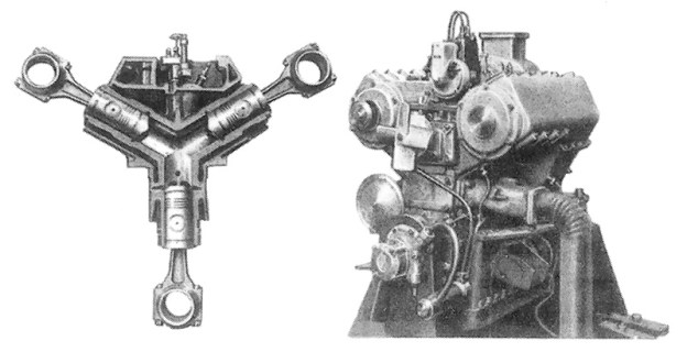
Michel continued his development of the three-cylinder opposed-piston engine design and reverted back to the use of a crankshaft, albeit three of them. The three cast iron cylinders were arranged in a Y configuration, and all the cylinders were spaced 120 degrees apart. Air was fed into the upper two cylinders via ports in the cylinder walls. The exhaust ports were in the wall of the lower cylinder, and exhaust gases were expelled through the side of the lower cylinder bank. The lower piston had a 24 degree lead time over the upper pistons to ensure good cylinder scavenging. The exhaust ports alone were uncovered for 32.6 degrees of crankshaft rotation. For the next 76.3 degrees, both the exhaust and intake ports were uncovered, followed by another 15.8 degrees where only the intake ports were unobstructed.

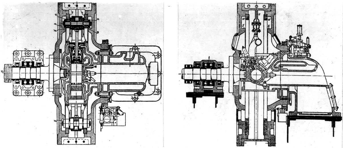
Section view of the Michel three-crank opposed-piston engine. The crankshafts are marked A, B, and C. Clearly seen are the liquid-cooling (W), scavenging air (S), and exhaust (E) passageways. Note the unique piston head shape that creates a combustion chamber.
The three-cylinder engine had a 15 to 1 compression ratio. The engine’s three pistons converged on a common combustion chamber where a fuel injector was positioned vertically between the upper two cylinders. The piston heads were specially designed to create a combustion space when the pistons came together. Fuel injection started 19 degrees before the exhaust piston reached top dead center and continued for 21 degrees. The engine’s configuration resulted in very efficient combustion due to the high degree of turbulence and thorough mixing of air and fuel.
All three crankshafts rotated in the same direction. There was an additional, projecting crank at the end of each crankshaft. Attached to this crank was a triangular casting that connected the crankshafts together at the rear of the engine. This triangular member drove the generator and the water, oil, and Bosch fuel injection pumps. The fuel injection pump was positioned in the upper V of the engine.

Front and rear section view of the Michel three-cylinder opposed-piston engine. Note on the rear view, the triangular member connecting the three crankshafts and the rectangular scavenging air pump at its center.
A scavenging air pump was situated at the rear of the engine. This air pump was a rectangular frame formed integral with the triangular member that joined the crankshafts. The air pump took advantage of the frame’s rotary motion. The rectangular frame was sealed except for strategically placed passageways. A slide valve formed a partition within the frame and was fixed so that it could only move up and down. As the engine ran, the space within the frame on either side of the slide valve partition alternately expanded and contracted, creating a pumping action. Air was fed from the slide valve at 21-25 psi (1.4-1.7 bar) to the cylinders via internal passageways. Power from the engine was taken from the lower crankshaft.
In the early 1930s, Michel relocated to Hamburg, Germany and built a few of his redesigned, three-cylinder, opposed-piston engines. Like the cam engine, the cylinder group was somewhat modular, and additional groups could be added to the design. The engine with the smallest cylinder size had a 1.9 in (47 mm) bore and a 3.1 in stroke (80 mm). This engine had four three-cylinder groups and a total displacement of around 102 cu in (1.7 L) from its 12 cylinders. It produced 60 hp (45 kW) at 2,000 rpm and weighed 616 lb (279 kg).

A Michel 3-cylinder group and its engine. This engine has one cylinder group. Note its short length and the single exhaust port of the lower cylinder..
A larger three-cylinder engine was built with a 2.6 in (67 mm) bore and a 4.7 in stroke (116 mm). Each three-cylinder group would displace around 75 cu in (1.2 L) and had an output of around 45 hp. A one cylinder group and a four cylinder group were made. The four cylinder group engine had a displacement of 299 cu in (4.9 L). This engine produced 180 hp (134 kW) at 2,000 rpm and weighed 1,188 lb (539 kg).
Although the engine’s size was not stated, a Michel engine was extensively run in a truck testbed and reportedly gave good results. However, the engine never entered production. The Michel line of engines was supposed to be made under license in the United Kingdom by Tekon Development Ltd and called the Stellar. However, it does not appear that any engines were made.
*Please note, the Hermann Michel discussed in this article is not the Nazi war criminal with the same name.

A Michel engine with four groups of three opposed-piston cylinders. This engine had a total of 12 cylinders. Note the four square exhaust ports on the lower cylinder bank.
Sources:
– “Two-Stroke-Cycle Internal-Combustion Engine” US patent 1,603,969 by Hermann Michel (granted 19 October 1926)
– “Engine, and Particularly Internal Combustion Engine” US patent 1,568,684 by Hermann Michel (granted 5 January 1926)
– “Comments on Crankless Engine Types” NACA Technical Memorandum No. 462, May 1928 (Translated from “Motorwagen” 20 November 1927) 12.8 MB
– High Speed Diesel Engines by Arthur W. Judge (1941)
– The Modern Diesel fourth edition no date Illiffe & Sons Ltd
– New Motoring Encyclopedia (complete work 1937)
– Ungewöhnliche Motoren by Stefan Zima and Reinhold Ficht (2010)

This is wounder full, thank you for sharing.
I would have loved to have heard one of these big 3 cylinder engines : imagine a 5litre firing as a single at 100rpm ,
I animated the cam engine for Doug Self (http://www.douglas-self.com/MUSEUM/POWER/unusualICeng/cam-IC/cam-IC.htm#mich)
I would love to also, did you see the commers engine? /watch?v=JrAoj5Cuu68
Also why dont you build one your self? calculating fuel energy, air heat is easy.
best of luck.
Would an engine like this make sense in a diesel submarine, making less noise as a result of far fewer RPMs?
The original engines with the slow rpm had numerous cycles per each revolution. In the drawing, the cam ring had six cycles. Because the engine was a two-stroke, it would have six power strokes for each revolution of the crankshaft. The power stroke (explosion) is where most of the noise is made. Yes, the engine would have a lower rpm, but it would be making the same amount of noise as an engine running at six times higher rpm (because of the six power stokes for each revolution). However, if a gear reduction was typically needed, the lower rpm of the Michel engine could eliminate that necessity.
the lower noise would comm from increased efficiency i.e. less losses. search read about Achates opposed pistons engine. OPEs are the future.
Great find and write up! Now I see where the crankless engines have their historical antecedents. Any ideas on why the crankless designed was abandoned? Any idea if Junkers or Napier had any contact with Michel? The tri-piston combustion chamber does not appear to offer great advantages, and a least one disadvantage of the dome topped pistons, over the opposed (180 degree) piston design with it’s flat topped pistons. Is there an inherent breathing advantage to having twice as many pistons flowing in as out in Uniflow scavenging design?
In the if only category, if Junkers or more likely Michel had cottoned on to (become interested in) replacing the tri-pisotn combustion chamber with three bi-piston and figured out how to spin one crank the opposite direction, we could have had a Deltic like engine in an S Boote instead of the giant Mercedes-Benz diesels.
Thank you for the great work and contemplating these questions and fantasies.
Glad you liked the article. I think that crankless engines were mostly abandoned because of whatever advantages they offered were outweighed by their drawbacks. It is a similar story with sleeve-valve and rotary engines. I know of no contact between Junkers and Michel, and I think Napier got their start with opposed-piston engines via Junkers. I think there is some advantage in having a greater intake capacity than exhaust, but obviously many engines manage this without having three pistons for each combustion chamber.
I would guess that the cam type rotor crank cannot convert the power to rotary motion, the pins from the rod to he cam grove would only have a line contact surface area, while in regular crank the contact area is the area of the journals.
“” Is there an inherent breathing advantage to having twice as many pistons flowing in as out in Uniflow scavenging design?””
Yes, there is, it is actually the point of OPed engines, the OP engines are more efficient because they have double the area of the movable working surface boundary, i.e. they have more surface to convert heat/pressure into power, in-fact at TDC they have 100% more area than regular head engines, meaning they have two piston crowns, some engineers call it the work area per volume. this off course leads to double the speed of pressure reduction and conversion to power/work, in other words the engines will be able to convert the energy much faster, this also means you can run ever high compression ratios and since the stork will be 50% shorter this means less acceleration and G forces generated by the pistons which means less stress on the crank and parts which means double the RPM which means more power.
Click to access 2011COMVECThermodynamicAdvantagePaper-sm.pdf
https://www.sciencedirect.com/science/article/pii/S1876610217361222
https://www.sae.org/publications/technical-papers/content/2011-01-2216/
https://www.researchgate.net/publication/301367369_Thermodynamic_Benefits_of_Opposed-Piston_Two-Stroke_Engines
https://www.researchgate.net/publication/280655932_Thermodynamic_simulation_comparison_of_opposed_two-stroke_and_conventional_four-stroke_engines
Click to access 7229c7099403e6c70f3bde64456242875df3.pdf
and forget about two stroke OP engines, this guy (below) created four stork with a new, yes new type of valves.
Two stroke still suffer from the problem of hot rings as they pass exhaust ports on the side of the cylinders, i think they call it the dry sump problem for it dries the sump out of oil. achestes are testing their op engines in Saudi Arabia hoping 2020 they will be commercial.
Click to access Achates-Power-Aramco-Joint-Development-Agreement-News-Release.pdf
but that is not the big deal
this guy is the future https://www.youtube.com/watch?v=1VnCBkaYa0Y
best.