Monthly Archives: March 2015

Dorand Gyroplane G20 complete 1947

Dorand Gyroplane G.20 (G.II)

By William Pearce

Since the early 1900s, Frenchman Louis Bréguet was interested in rotorcraft. But, the technical challenges of controlling such machines and the lack of suitable power plants led Bréguet to pursue the development of aircraft instead. In the late 1920s, Bréguet’s interest returned to rotorcraft, and he created the Syndicat d’Etudes de Gyroplane (Syndicate for Gyroplane Studies) in 1931 with René Dorand as its Technical Director. The syndicate produced a successful experimental helicopter known as the Bréguet-Dorand Gyroplane Laboratoire, which first flew on 26 June 1935. The Gyroplane Laboratoire used two sets of two-blade, coaxial, contra-rotating rotors. No tail rotor was used, as the contra-rotating rotors cancelled out the torque reaction of the blades. The helicopter set a number of speed and distance records.

Dorand Gyroplane G20

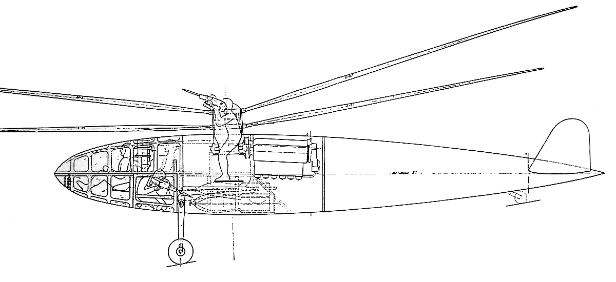
A drawing of the Dorand Gyroplane G.20 in what appears to be its final form. The drawing illustrates one of the two inverted Renault inline-six engines and the two-person cockpit.

In 1938, Dorand amicably parted with Bréguet and established the Société Française du Gyroplane (French Gyroplane Company), abbreviated SFG or just Gyroplane for short. The French Navy (Marine Nationale) commissioned the SFG to design a combat helicopter for costal defense and anti-submarine warfare. Dorand designed the new machine, and its layout was similar to that of the Gyroplane Laboratoire. The new helicopter was designated the Gyroplane G.20, but it is also known as the Dorand G.20 or the Dorand G.II.

The G.20 had a cigar-shaped fuselage of all metal construction. A butterfly tail was attached to the extreme end of the fuselage, and the tail’s control surfaces were fabric-covered. The streamlined nose of the G.20 was covered with plexiglass panels. The pilot sat in the nose of the helicopter with either one or two crewmen behind.

Dorand Gyroplane G20 org drawing

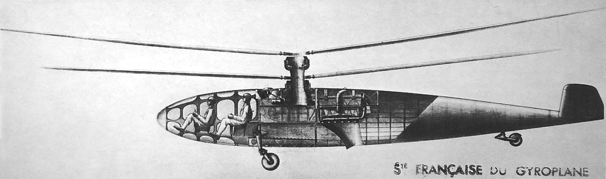
A drawing of the original Dorand G.20 with its three-man crew and rotor mast gunner turret. Note the side-mounted machine gun (pointed toward the rear) and the bomb load. An inverted, inline, six-cylinder, Renault engine is also visible. The rotors on the left are shown in their normal position, while the rotors on the right are at their maximum upward deflection.

At the center of the helicopter were two three-blade, coaxial, contra-rotating rotors. The distance between the rotors was 2 ft 2 in (0.65 m), and the lower rotor had a smaller diameter than the top rotor to ensure the blades would not collide. The upper rotor had a diameter of 50 ft 6 in (15.4 m), and the lower rotor’s diameter was 42 ft 8 in (13.0 m)—7 ft 10 in (2.4 m) smaller.  The magnesium blades were made of two parts: a box forming the leading edge and a separate trailing edge. As with the Gyroplane Laboratoire, articulation of the blades allowed for both cyclic and collective pitch control, and no tail rotor was used.

The rotor blades were powered by two Renault 6Q-04 engines. The 6Q was an air-cooled, inverted, inline, six-cylinder engine with a 4.72 in (120 mm) bore and a 5.51 in (140 mm) stroke. The engine’s total displacement was 580 cu in (9.5 L). The 6Q-04 was supercharged and produced 240 hp (179 kW) at 2,500 rpm up to 13,123 ft (4,000 m). A special gearbox transferred power from the engines to the rotors. If one of the engines were to fail, that engine would be automatically disconnected, and the remaining engine would power both sets of rotors.

Dorand Gyroplane G20 org drw

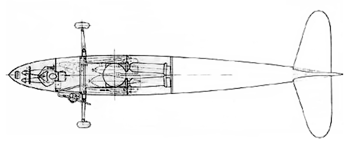
This top view drawing of the G.20 clearly shows the side-mounted machine gun and engine placement. The outline of bombs can be seen under the rotor mast.

The G.20 was supported by two main wheels and a tailwheel. The tail and main wheels all retracted backward into the fuselage and were fully enclosed by gear doors. The space in the fuselage between the main gear and below the rotors was for either bombs or a depth charge. In addition, Dorand’s original design included a machine gun mounted on the helicopter’s side and a turret mounted on top of the rotor mast—with the guns operated by separate crewmen. The mast turret was unique in that it was essentially a hollow drum to which the rotors were attached. A gunner occupied the center of the drum and had a 360 degree field of fire. However, all armament and the rotor turret were omitted from the G.20. Most sources list the completed G.20 as having a two-person crew consisting of a pilot and copilot. The helicopter’s final role was defined as observation, liaison, and mail-carrying.

The G.20’s fuselage had a length of 36 ft 4 in (11.08 m) and a height of 10 ft 3 in (3.13 m). The helicopter’s empty weight was 3,086 lb (1,400 kg); normal operating weight was 5,512 lb (2,500 kg), and maximum weight was 6,614 lb (3,000 kg). The G.20’s hover ceiling was 9,843 ft (3,000 m), and it had a maximum ceiling of 16,404 ft (5,000 m). The helicopter’s range was 497 mi (800 km). Its cruise speed was 103 mph (165 km/h), and its maximum speed was 155 mph (250 km/h) at 8,202 ft (2,500 m).

Dorand Gyroplane G20 complete 1947

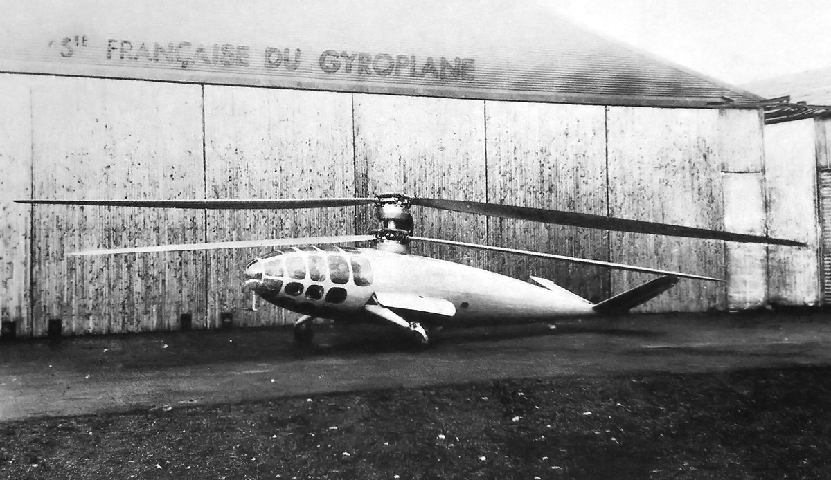
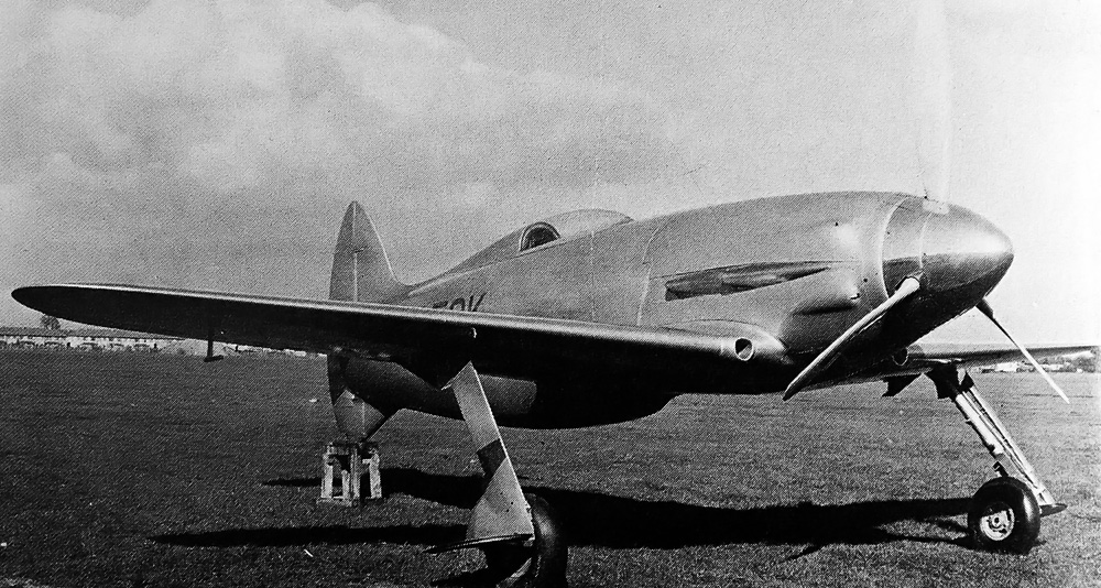
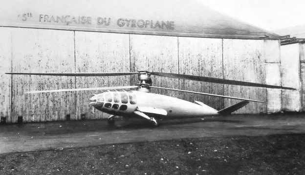
The completed Dorand G.20 after World War II. With the machine guns no longer part of the design, nothing is left to interrupt the helicopter’s sleek lines. Note the long gear door.

Construction of the G.20 started in Guethary in south-western France, near Spain. When the German Army invaded France in 1940, the helicopter was moved to Chambéry in south-eastern France, near Italy, and construction resumed. By this time, Marcel Vuillerme had taken over the project from Dorand. As the Germans pushed into southern France, the G.20 was discovered. The Germans showed little interest in the helicopter and allowed its construction to continue, albeit slowly.

The G.20 was completed in 1947 and underwent ground tests. It was the French officials who now showed little interest in the project, and funding was not forthcoming. Its estimated performance was optimistic, and while its streamlined appearance and retractable gear appeared futuristic, in many ways the G.20 was obsolete after war-time helicopter developments made in the United States and Germany. Further development and testing of the G.20 was abandoned, and the helicopter never flew. However, the SFG continued to develop helicopters for a time. The SFG worked with Bréguet to construct a four-passenger helicopter, the G.11E, which first flew in 1949. The G.111 was a follow-on project that first flew in 1951. The SFG went out of business in 1952.

Breguet G11E

The G.11E was designed by SFG after the G.20. It was built by Bréguet and powered by a 9-cylinder Potez 9E radial engine. It first flew in 1949 and had a layout similar to the G.20.

Sources:
Les Avions Breguet 1940/1971 by Jean Cuny and Pierre Leyvastre (1973)
René Dorand: 50 Ans de Giraviation by Pierre Boyer (1992)
http://en.wikipedia.org/wiki/Breguet-Dorand_Gyroplane_Laboratoire
http://en.wikipedia.org/wiki/Breguet_G.11E

Napier-Heston Racer front 3-4 2

Napier-Heston Racer

By William Pearce

Near the end of World War I, D. Napier & Son built one of the most outstanding aircraft engines of all time: the 12-cylinder Lion. Lion production continued through the 1920s and 1930s, and other Napier aircraft engines did not achieve a level of success anywhere near that of the Lion. In the 1930s, Major Frank Halford was the head aircraft engine designer at Napier and was working on H-type engines. Compared to contemporary aircraft engines, Halford’s new engines used a smaller cylinder bore and stroke and ran at a higher rpm. In the late 1930s, Halford’s latest engine was the Sabre—a sleeve valve engine with 24 cylinders of 5.0 in (127 mm) bore and 4.75 in (121 mm) stroke. The Sabre displaced 2,238 (36.7 L) and was capable of over 2,000 hp (1,491 kW) and speeds up to 4,000 rpm.

Napier-Heston Racer front 3-4

The Napier-Heston Racer’s sleek lines and wide-track undercarriage are apparent in this view of the aircraft taken at the Heston Airport.

Napier wanted a way to demonstrate their new aircraft engine to the world. In its earlier days, the Lion had powered aircraft used to set world speed records. Since 1937, the Germans had held the landplane 3 km (1.86 mi) world speed record at 379.38 mph (610.55 km/h), and since 1934, the Italians had held the absolute 3 km (1.86 mi) world speed record at 440.682 mph (709.209 km/h). Napier felt a specially designed aircraft powered by a Sabre engine would be capable of setting a new speed record at over 480 mph (772 km/h), beating both the Germans and Italians. Not only would this achievement be great marketing, it would also bring the record back to Britain and embarrass Hitler’s Germany and Mussolini’s Italy.

Under lead designer Arthur E. Hagg, Napier laid out its racer design in mid-1938. Hagg previously designed the de Havilland DH.91 Albatross transport, and the two aircraft share some family resemblance. The racer’s sole purpose was to break the 3 km (1.86 mi) world speed record, and it was not intended as a testbed for the Sabre engine. The British Air Ministry was unwilling to financially support the project, but Lord Nuffield (William Richard Morris) stepped forward to independently fund the construction of two aircraft. In addition, a number of vendors donated parts and services or offered them at cost. Since Napier did not have the resources to construct the racer, the Heston Aircraft Company was selected to build the aircraft in late 1938. The Heston team was led by George Cornwall. The association between Napier and Heston gave the aircraft its popular name: the Napier-Heston Racer. The aircraft is also known as the Nuffield-Napier-Heston Racer, the Heston J.5 High-Speed Aircraft, and the Heston Type 5 Racer.

Napier-Heston Racer rear 3-4

The Napier-Heston Racer was painted silver with dark blue registration letters. Many layers of aircraft dope were applied to the birch ply sheeting that made up the exterior of the aircraft; this created a surface free from even the most minor of imperfections.

To expedite construction, the Napier-Heston Racer was built almost entirely of wood. The wing spars were made from compregnated wood of multiple laminations bonded with resin under high pressure. The fuselage frame and stringers and wing ribs were made of spruce. The wings and fuselage were covered with birch ply sheets. Split flaps were incorporated into the wings. The control surfaces had aluminum alloy frames and were covered with fabric. A variable-ratio control system was designed for the elevator. This system kept the elevator movements small when the control stick was near the neutral position. As the control stick was moved farther from neutral, the relative elevator movement became greater. This system was employed so that very precise elevator movements could be achieved at high speeds.

The Napier-Heston Racer was fitted with one of the first six Sabre I prototype engines, but its boost was increased. The standard Sabre I engine produced 2,000 hp at 3,700 rpm, but the racer’s engine produced 2,450 hp (1,827 kW) at 3,800 rpm. The racer had a 10 ft 9 in (3.28 m) diameter, metal, three-blade, de Havilland constant-speed propeller. Wing root intakes led to the engine’s supercharger. A radiator was housed in a duct under the aircraft. The radiator’s upper and lower surfaces were sloped back and formed a deep V in the duct. After air passed through the radiator, it was expelled under the horizontal stabilizer on both sides of the tail. A channel above the radiator skimmed off the turbulent boundary layer, allowing it to bypass the radiator. The wide-track (14.8 ft / 4.5 m) main gear retracted fully into the wings, and a small tail skid was incorporated into the fixed fin of the tail. After many layers of aircraft dope were applied, the fit and finish of the racer was near perfection.

Napier-Heston Racer left

The rather small size of the Napier-Heston Racer is illustrated in this photo. The radiator’s intake duct can be seen under the aircraft, and its exit duct under the horizontal stabilizer. Note the bulges in the cowling to allow clearance for the Sabre’s cylinder banks.

Between the engine and fully enclosed cockpit was a 73 gallon (276 L) fuel tank. At full throttle, the aircraft’s endurance was only 18 minutes. The racer had a wingspan of 32 ft (9.75 m), a length of 24 ft 7 in (7.50 m), and a height of 11 ft 10 in (3.61 m). Its fully loaded weight was 7,200 lb (3,267 kg). All tolerances were kept to a minimum, and the racer was highly polished to remove any imperfections. The aluminum engine cowling had four bulges to allow clearance for the Sabre’s cylinder banks. The cowling sealed so tightly that small air vents were installed on the bulges to ensure that no combustible vapors built up in the engine compartment.

The first flight of a Sabre engine occurred on 31 May 1939. The engine was installed in a Fairey Battle flown by Chris Staniland. The Sabre-powered Battle had accumulated a number of hours before the special engine in the Napier-Heston Racer was first run on 6 December 1939. The racer was painted silver, with the registration of G-AFOK painted in dark blue. Taxi tests began on 12 March 1940 at Heston Airport. The engine and taxi test did not reveal any issues with control or engine cooling.

The Napier-Heston Racer’s first flight was delayed by weather but finally occurred on 12 June 1940. Squadron Leader G. L. G. Richmond was at the controls and flew the aircraft off from the 3,900 ft (1,189 m) grass field at Heston Airport. Reportedly, Richmond chose to make this flight without the canopy in place. Shortly after liftoff, the Sabre engine rapidly overheated, and Richmond tried to quickly bring the plane in for a landing. Sources disagree on exactly what happened next.

Napier-Heston Racer front

Two of the small engine compartment vents can just be seen on the upper bulges of the cowling. The exterior of the aircraft was kept as aerodynamically clean as possible.

Some sources state that Richmond was preoccupied with the emergency and was also being scalded by the overheated cooling system. They claim that he may have experienced some difficulty mastering control of the variable-ratio elevator, as he had almost touched down after a steep approach when the aircraft rose sharply back into the air and stalled. Other sources point out that the racer did not exhibit any cooling issues during the numerous ground engine runs and that Richmond was scalded when the coolant pipes burst as a result of the hard landing after the stall. They contend that the aircraft’s elevator became ineffective as a result of low speed and that it was possibly in the wings’ turbulent airflow during the steep pitch up before the stall. While some sources state the Sabre engine seized, others report the ignition was on and the engine was running but that Richmond did not advance the throttle because of its overheated state.

Richmond’s flight in the Napier-Heston Racer was only about six minutes, and he never retracted the gear. After liftoff, he immediately brought the aircraft around for landing. Richmond’s actions indicate he felt something was wrong very early on. While a burst cooling pipe would explain the cooling issues and Richmond’s scalding, and control issues with the elevator would explain the odd altitude deviations in the aircraft’s final moments, the exact issues and sequence of events may never be known.

Napier-Heston Racer front 3-4 2

The wing root intake scoops that provide air to the Sabre engine can clearly be seen in this photo. Two three-into-one exhaust manifolds on each side of the racer collected the Sabre’s exhaust gases.

The end result was that the Napier-Heston Racer stalled about 30 ft (9 m) above the grass runway and hit the ground hard. The impact broke the landing gear, the left wing, and the rear fuselage just behind the cockpit. Fortunately, Richmond was able to walk away from the wreck. With the war against Germany underway, no attempt was made to repair the Napier-Heston Racer. The racer’s Sabre engine was not badly damaged. It was rebuilt and installed in a production Hawker Typhoon that was used during the war. Although the second racer, registered as G-AFOL, was around 60% complete, it was never finished. The Napier-Heston Racer project had cost Lord Nuffield £50,000 to £100,000.

Between the time the Napier-Heston Racer was conceived and its first flight, Germany had increased the absolute world speed record to 469.221 mph (755.138 km/h). However, the Chief Technician and Aerodynamicist at Heston Aircraft, R. A. Clare, had estimated that the Napier-Heston Racer could achieve a maximum of 508 mph (818 km/h) over the 3 km (1.86 mi) course. While the true capabilities of the racer will never be known, attempts have been made to create a flying replica. Due to the high cost of such a project and the extreme rarity of Sabre engines, for now, a Napier-Heston Racer replica remains just a dream.

Napier-Heston Racer right side

The Napier-Heston Racer ready to fly at the Heston Airport. It is unfortunate that the aircraft never had a chance to demonstrate its true potential.

Sources:
– “The Napier-Heston Racer” by Bill Gunston Aeroplane Monthly (June 1976)
– “Napier-Heston Racer postscript” Aeroplane Monthly (August 1976)
– “A Co-operative Challenger” Flight (15 April 1943)
– “The Heston Napier Monoplane” by H. J. Cooper The Aero Modeller (August 1943)
By Precision Into Power by Alan Vessey (2007)