By William Pearce
As the popularity of personal automobiles increased, passenger train travel decreased. In the United States, the decline quickened in the 1960s as the Interstate Highway System came on line and jet engines made air travel affordable. Railroad companies realized their long haul passenger service could not compete with the more modern forms of transportation but felt they could develop a better service in the short haul and mid-haul markets to win back customers.

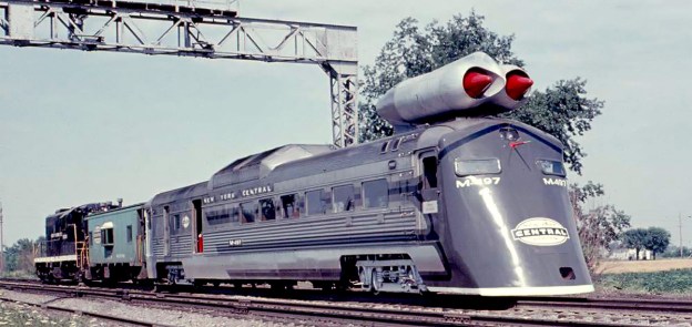
New York Central’s M-497 Black Beetle tested the feasibility of using jet engines to propel a train at high speed on a conventional track. M-497 is seen here with a support car and engine. Note the red pitot tube just under the lights on the front of the train.
In 1965, James Wright, director of the New York Central (NYC) Railroad’s Technical Research Center, thought of an experiment to drastically increase a train’s speed in the shortest amount of time and with minimal changes to the train and track. Simply put, Wright’s idea was to use a jet engine to propel the train to much higher speeds. Wright discussed his proposal with the president of NYC, Alfred Perlman, but the talks died off.
Around a year later, in early June 1966, Wright received a call from Perlman authorizing the jet engine experiment and requesting that it be completed in 30 days. The project was a daunting one; not only was a train needed that could be modified for jet propulsion, but the team also had to find jet engines and a section of track suitable for high-speed tests. The rush was on to turn a visionary idea into a tangible reality.

The completed jet-powered M-497 and some of the crew that worked tirelessly at the Collinwood Technical Center to create the locomotive.
For the experiment, the NYC decided to use a Budd Company Rail Diesel Car-3 (RDC-3). The RDC-3 was a self-propelled commuter railcar powered by two 275 hp (205 kW) Detroit Diesel six-cylinder engines. The RDC-3 accommodated 48 passengers, was 85 ft (25.9 m) long, and had a top speed of 85 mph (137 km/h). The RDC-3 chosen was No. M-497, which NYC had purchased 13 years earlier, in 1953. M-497 was the first of three RDC-3s that the NYC owned. For $5,000, the NYC was able to obtain from Davis-Monthan Air Force Base in Arizona a surplus jet pod from a Convair B-36 Peacemaker. The pod contained two General Electric J47-GE-19 jet engines capable of 5,200 lb (23.1 kN) thrust each.
M-497 and the J47 jet engines were relocated to NYC’s Collinwood Technical Center near Cleveland, Ohio. Under Donald Wetzel, the Assistant to the Director of Technical Research, modifications were made to combine the jet engine pod and railcar. Ruth Wetzel, Don’s wife and a commercial artist, drew up the basic sketches for the jet engine placement as well as an aerodynamic fairing for the front (B end) of the blunt-nosed RDC. She also outlined the paint scheme for the completed M-497. The fairing combined with the paint scheme ultimately earned M-497 its Black Beetle nickname.

This picture of the rear of M-497 shows the covered door and the fairings that extended down from the sides of the train. These changes to the Budd RDC-3 railcar improved its aerodynamics.
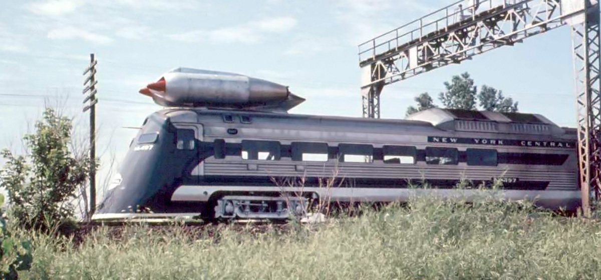
The engine pod was mounted above the front of the railcar at a five degree nose-down angle. The pod’s installation on the train was inverted as compared to the B-36, so the engines were rotated 180 degrees in their housings. The J-47 engines were converted to run on diesel fuel, and additional fuel tanks were installed in the mail section of the RDC. Some seats were removed from the front of the RDC to allow for the jet engine mounting structure. The drive shafts from the original diesel engines were disconnected, and M-497 was outfitted for the tests with more than 50 instruments in its baggage area. After scale models were verified in a wind tunnel, the aerodynamic fairing was built up over the front of the RDC. The fairing added 5 ft 7 in (1.7 m) to M-497’s length, making the modified train 90 ft 7 in (27.6 m) long. Based on wind tunnel tests, the back (A end) of the car was also slightly modified (the door was faired over), and the car’s sides were extended down to further improve its aerodynamics.
Wetzel was selected as M-497’s engineer because of his experience with the project. He also had experience with jet engines from his service in the military. M-497 was taken to a stretch of track between Toledo, Ohio and Butler, Indianan that had been specially prepared (rails welded together) for high-speed runs. This location offered a 68.5 mile (111 km) section of straight, multiple track. Initial tests revealed that the hot exhaust from the jet engines passed over the roof radiators for the diesel engines, which were used to power the brakes and accessories of the RDC. The lack of cooling air caused the engines to get too hot, and they shut down automatically. The auto-shut-down feature was disabled for subsequent runs; although the engines ran hot, the runs were short and the engines were not producing much power, so they were not in danger of being damaged. No other serious issues were encountered, and the high-speed tests proceeded.
Never intended to be put in service or production, the J47 jet engines propelled M-497 to a record speed of 183.85 mph (295.88 km/h).
For the high-speed runs, a Beechcraft Model 18 flew ahead of M-497 to make sure the track was clear. On the second run on 23 July 1966, with Wetzel, Wright, Perlman, and other engineers on board, M-497 raced eastward on the track from Butler, Indiana. Wetzel had been asked to run around 180 mph (290 km/h), but as he approached the speed trap at milepost 352 (near Bryan, Ohio), he saw M-497 was traveling at 196 mph (315 km/h). He reduced power, and M-497 was recorded at 183.85* mph (295.88 km/h). This was and still is the fastest speed a train has traveled on open track in the United States. M-497 finished the run near Stryker, Ohio, some 21 miles (34 km) from the start. As a precaution, railroad ties were placed across the track near Toledo, Ohio to derail M-497 in case it ran away.
Additional tests were conducted the next day, but they never approached the speed from the previous day. One of the J47 engines refused to light. M-497 accelerated on one engine until the dead engine could be air-started.
After a short time in the limelight, M-497 was returned to its standard RDC-3 configuration and pressed back into normal service. The NYC’s M-497 had shown that high-speed rail service was possible on a conventional track, and that was the true goal of the experiment. The train’s configuration was not practical, as the jet engines required a vertical clearance in excess of what was standard at the time. In addition, the jet-powered M-497 did not have a reverse and needed another engine to pull it back to the starting point after a run. Of course, these problems could have been overcome with a specially designed engine, but it was already the sunset of rail travel in the United States.

The jet-propelled M-497 at speed on the track between Butler, Indiana and Stryker, Ohio.
NYC, which had been in business since 1853, merged with the Pennsylvania Railroad in 1968 and formed the Penn Central Transportation Company (PC). In 1970, PC became the largest company to file for bankruptcy protection. PC stumbled on until 1976 when it was finally broken up. M-497 outlasted both NYC and PC. Although given a new number with each new owner, the RDC-3 once known as M-497 and the fastest train in the United States was in service until 1977 and was finally scrapped in 1984. A plaque commemorating the record run was dedicated in Bryan, Ohio on 14 November 2003.
*Some modern sources list the speed as 183.681 mph (295.606 km/h), but this does not appear to be correct. Contemporary information and the plaque dedicated in 2003 record the speed as 183.85 mph (295.88 km/h).
Below is a video made by General Electric commemorating Don Wetzel and the M-497’s speed run.
Sources:
– Flight of the M-497 by Hank Morris with Don Wetzel (2007/2012)
– http://www.gereports.com/post/77176433669/the-jet-train-roars-back-don-wetzel-talks-about
– http://www.gereports.com/post/91355522740/building-a-jet-propelled-train-was-not-rocket
– http://www.american-rails.com/m-497.html
– http://en.wikipedia.org/wiki/Budd_Rail_Diesel_Car
– http://en.wikipedia.org/wiki/New_York_Central_Railroad
– http://en.wikipedia.org/wiki/Penn_Central_Transportation_Company