By William Pearce
In November 1936, the Dutch aircraft manufacturer Koolhoven surprised many by bringing a very advanced fighter aircraft mockup to the Paris Salon de l’Aviation (Air Show). Mounted on stands to make it appear suspended in flight, the Koolhoven FK.55 mockup caught everyone’s attention. The impressive mockup was so detailed that anyone who did not study it for a period of time would think that it was a real aircraft. But converting the unique ideas showcased in the mockup into a workable aircraft would pose serious problems for Koolhoven.
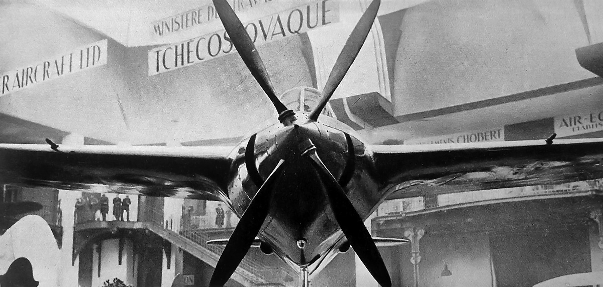
The sleek lines of the Koolhoven FK.55 can be seen in this image of the mockup at the 1938 Paris Salon de l’Aviation. Note the machine guns mounted in the wings and the radiators in the aircraft’s nose. The outline of the aircraft’s main gear is just visible under the wings.
The FK.55 was designed by company founder Frederick (Frits) Koolhoven. The mockup was of all wooden construction and featured an aerodynamic fuselage with a somewhat triangular cross section. One corner of the triangle formed the lower part of the fuselage, and the wings extended from the other two (upper) corners. The shoulder-mounted wings were well blended into the fuselage and located just behind the cockpit. The wing center section was built integral with the fuselage.
The FK.55 mockup did not include ailerons. Roll control was to be achieved by slot-spoilers in the outer wing sections. While the “slots” did exist, the “spoilers” were never installed on the mockup, and the slots were covered by aluminum panels. The pivot point of the retractable main landing gear was just off the aircraft’s center line. The legs of the main gear had a bend that allowed them to retract flush into the sides of the fuselage and underside of the wings. At the rear of the aircraft was a non-retractable tail skid.
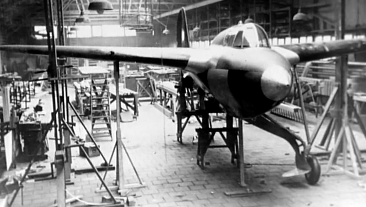
The elaborate FK.55 mockup being built at the Koolhoven factory. The very long main gear posed problems when adapted to the prototype.
It is not clear whether or not an engine was actually installed in the mockup. If an engine was installed, it was a Lorraine Pétrel water-cooled V-12 engine installed behind the cockpit and at the aircraft’s center of gravity. A shaft extended from the engine, ran under the pilot’s seat, and connected to a propeller gear reduction unit in the nose of the aircraft. The gear reduction unit enabled the use of contra-rotating propellers. Metal, fixed-pitch propellers were fitted to the prototype.
A cannon could be positioned behind the gear reduction unit and fire through the propeller hub. Each wing had a machine gun installed outside of the propeller arc. Radiators were located on each side of the mockup’s cockpit, between the nose and the wings. Two scoops under the mockup’s fuselage provided air to the engine. The position of the cockpit, forward of the wings and at the very front of the aircraft, provided the pilot an excellent view.
The FK.55 mockup had a 29.5 ft (9.0 m) wingspan and was 27.6 ft (8.4 m) long. The complete aircraft was forecasted to weigh 2,425 lb (1,100 kg) empty and 3,638 lb (1,650 kg) loaded. Estimated performance for the FK.55 included a top speed of 323 mph (520 km/h) at 13,123 ft (4,000 m) and a cruising speed of 280 mph (450 km/h) at the same altitude. The aircraft had an initial rate of climb of 2,983 fpm (15.2 m/s), a service ceiling of 31,496 ft (9,600 m), and a range of 559 mi (900 km).
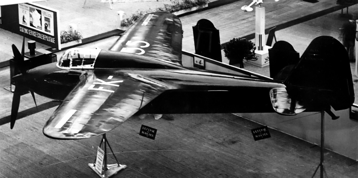
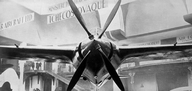
Suspended on stands, the FK.55 mockup was an impressive sight. Note the tail skid and the aluminum covers over the openings for the slot-spoilers.
Back in their factory at Waalhaven Airport in Rotterdam, Netherlands, the Koolhoven team went to work building a flying FK.55 prototype. The aircraft grew wider, longer, heavier, and slower than the original estimates. Each change necessitated another change as the FK.55 prototype came together, and what was once the sleek airframe of the FK.55 mockup eventually resembled a “pregnant duck” (in the words of one Dutch pilot).
The triangular cross section of the mockup’s fuselage had been replaced by a larger, mostly circular form. The wings had lost their blended look and now appeared tacked onto the fuselage. Strength issues with the long and complex landing gear necessitated using fixed gear temporarily attached to the fuselage until the retractable gear issues could be resolved. The front and middle sections of the fuselage were made from welded steel tubing, while the rear section and tail were made from wood. The wings were also made of wood and had split flaps and ailerons. The FK.55 maintained provisions for a 20 mm or 37 mm cannon to fire though the propeller hub, and each wing now housed two machine guns with 500 rpg. However, no armament was installed in the prototype.
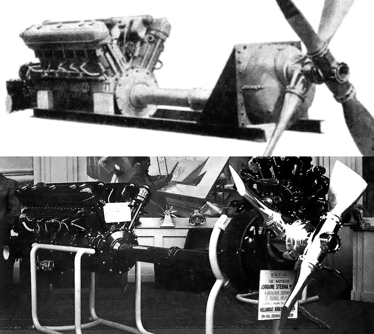
The Lorraine Pétrel engine (top) and the Sterna (bottom). Note how the front propeller rotates clockwise on the Pétrel but counterclockwise on the Sterna. Roughly translated, the sign under the Sterna reads, “The engine Lorraine Sterna 900 hp; Has offset reducer and double propellers; Dutch Koolhoven FK.55 in flight since 1938.”
There is some disagreement about which engine powered the FK.55 prototype. Most sources state an 860 hp (641 kW) Lorraine Pétrel 12Hars was used, but the 12Hars typically produced around 700 hp (522 kW). Some sources claim a 1,000 hp (746 kW) Lorraine Sterna was used. A 900 hp (671 kW) Sterna with an extension shaft and propeller gear reduction unit was displayed at the Paris Salon de l’Aviation in November 1938. A sign under the engine indicated that it was intended for the FK.55, but it is doubtful that the engine was ever installed in the aircraft, as the FK.55 flew before the 1938 Salon. In images of the FK.55 prototype, the gear reduction unit appears to be the one used with the Pétrel engine. In addition, the front propeller of the Pétrel engine rotated clockwise. The front propeller on both the FK.55 mockup and prototype also rotated clockwise; however, the front propeller of the Sterna engine rotated counterclockwise. Therefore, the Pétrel engine was most likely used, with the Sterna intended to replace it in the near future.
Two two-blade, adjustable-pitch, metal Ratier propellers were installed. The engine’s induction scoops had grown in size and were now positioned on the lower sides of the prototype. The radiators were retained in their original position but had also grown in size, again spoiling the aircraft’s aerodynamics.
The FK.55 prototype had a 31.5 ft (9.60 m) wingspan and was 30.3 ft (9.25 m) long. The complete aircraft weighed 3,527 lb (1,600 kg) empty and 5,027 lb (2,280 kg) loaded. The performance estimates for the FK.55 had been reduced to a top speed of 317 mph (510 km/h) at 11,811 ft (3,600 m) and a cruising speed of 280 mph (450 km/h) at the same altitude. The aircraft had an initial rate of climb of 1,367 fpm (6.9 m/s), a service ceiling of 33,136 ft (10,100 m), and a range of 528 mi (850 km).
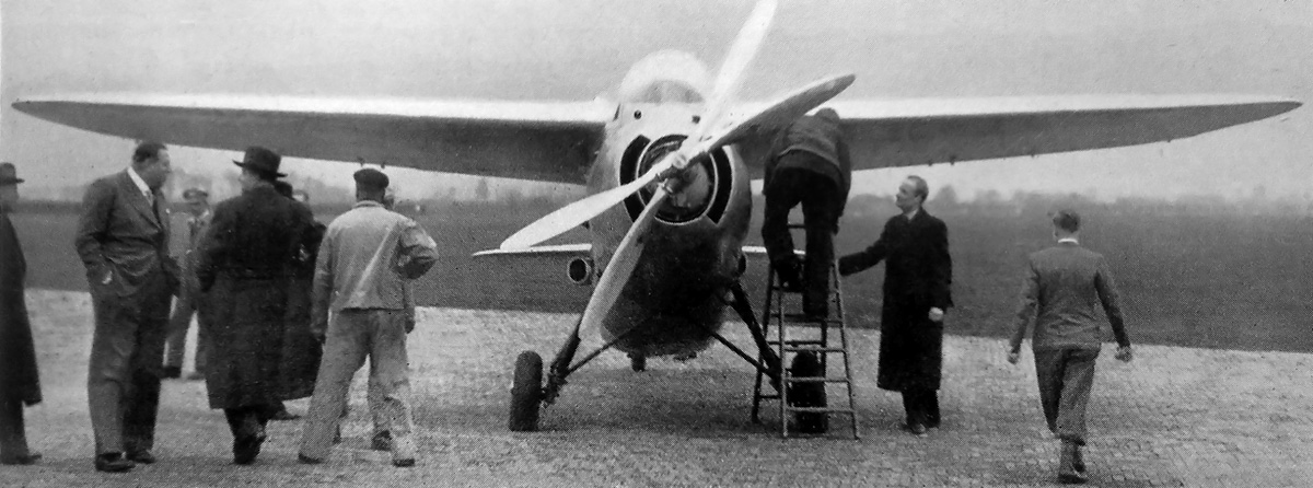
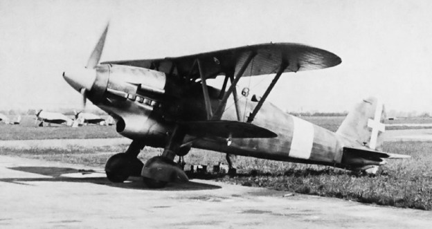
The FK.55 prototype was an odd and awkward aircraft, especially when compared to the mockup. Note the fixed landing gear and that the front propeller turned clockwise (when viewed from the rear).
In June 1938, the FK.55 was trucked to Welschap Airfield, a more secluded location for flight testing. The prototype was given the serial number 5501 and had been registered as PH-APB, but the registration was never applied to the aircraft. On the morning of 30 June 1938, Koolhoven pilot Thomas Coppers conducted high-speed taxi tests and hopped the FK.55 into the air on three separate occasions. Later that afternoon, Coppers took the FK.55 into the air for its first flight. Shortly after takeoff, Coppers made a 180 degree turn and quickly landed with the wind. Frits Koolhoven approached the aircraft, where he and Coppers engaged in an animated discussion regarding the FK.55. Some sources state that Coppers had found the cockpit unbearably hot. The taxi test should have given some indication of the heat experienced in the cockpit. Whatever the reason, the FK.55 never flew again.
The FK.55 mockup appeared to be a maneuverable fighter aircraft that afforded the pilot an excellent view, and its contra-rotating propellers eliminated engine torque, making the aircraft manageable for inexperienced pilots. The FK.55 prototype was an odd, ungainly aircraft that was underpowered and incomplete. The Koolhoven team endeavored to rework the FK.55’s design, changing to low wings and a Lorraine Sterna engine of at least 1,100 hp (820 kW), but Frits Koolhoven himself wanted nothing more to do with the aircraft. On 10 May 1940, a German bombing raid struck the Waalhaven Airport. The FK.55 mockup and prototype were destroyed, along with the entire Koolhoven factory, affectively putting an end to the company.
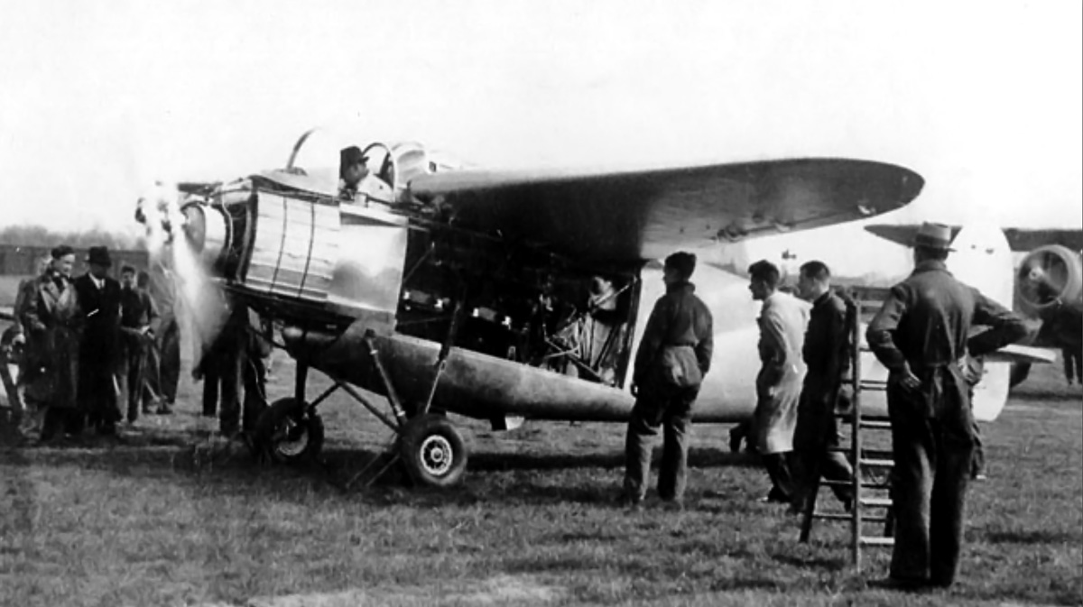
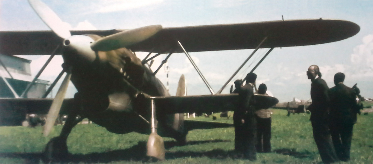
When viewed from the side, the FK.55 prototype had a rather “pregnant” appearance. This image illustrates how the pilot was positioned between several heat sources.
Sources:
– Jane’s All the World’s Aircraft 1936 by C. G. Grey and Leonard Bridgham (1936)
– Jane’s All the World’s Aircraft 1937 by C. G. Grey and Leonard Bridgham (1937)
– Jane’s All the World’s Aircraft 1938 by C. G. Grey and Leonard Bridgham (1938)
– The Complete Book of Fighters by William Green and Gordon Swanborough (1994)
– Koolhoven Vliegtuigen by Theo Wesselink (2012)
– Les Moteurs a Pistons Aeronautiques Francais Tome I by Alfred Bodemer and Robert Laugier (1987)