Monthly Archives: March 2017

CTA - ITA Heliconair Convertiplano drawing

CTA / ITA Heliconair HC-I Convertiplano

By William Pearce

In 1923, Henrich Focke partnered with Georg Wulf to create Focke-Wulf Flugzeugbau (Aircraft Company) in Bremen, Germany. Focke became fascinated with helicopters and other rotorcraft in the 1930s. This interest led to what is considered the first practical helicopter, the Focke-Wulf Fw 61, which first flew in 1936. That same year, Focke was ousted from Focke-Wulf due to internal disagreements about allocating company resources. In 1937, Focke partnered with Gerd Achgelis, the Fw 61’s lead designer, to create Focke-Achgelis & Co in Hoykenkamp, Germany. The new company would focus on helicopter and rotorcraft designs.

CTA - ITA Convertiplano side

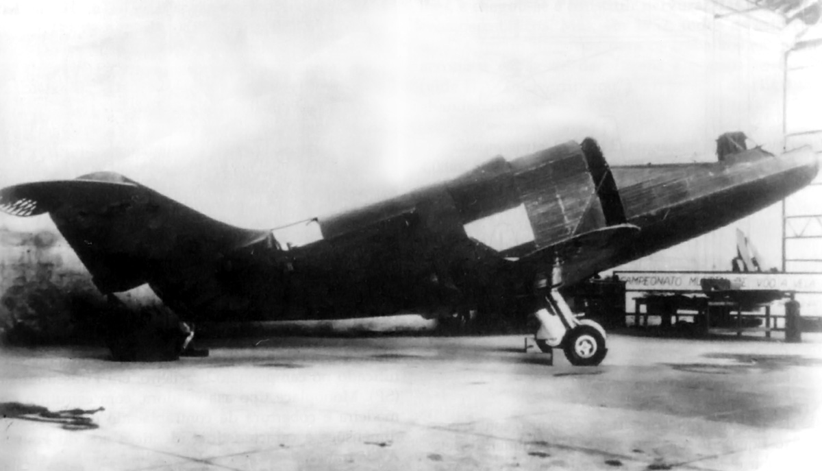
The Heliconair HC-Ib Convertiplano sits nearly finished in a hangar. The slit behind the cockpit was the intake for air used to cool the fuselage-mounted R-3350 engine. The scoop on the upper fuselage brought air to the engine’s carburetor. Note the Spitfire wings and main gear.

In 1941, the RLM (Reichsluftfahrtministerium or Germany Air Ministry) requested that Focke-Achgelis design a fighter capable of vertical takeoff and landing (VTOL). Focke-Achgelis responded with the Fa 269 design, which was a tiltrotor convertiplane. The Fa 269 had two rotors—one placed near the tip of each wing in a pusher configuration. The rotors were powered by an engine housed in the aircraft’s fuselage via extension shafts and gearboxes. The rotors and extension shafts leading from the right-angle gearboxes mounted in the aircraft’s wings rotated down to “push” the Fa 269 into the air, achieving vertical flight. Once airborne, the rotors and shafts would slowly translate back into the wing to propel the aircraft forward, allowing the aircraft’s wings to provide lift. The project moved forward until 1944, when much of the developmental work, including models, a mock-up, and gearboxes, was destroyed in an Allied bombing raid.

CTA - ITA Heliconair Convertiplano

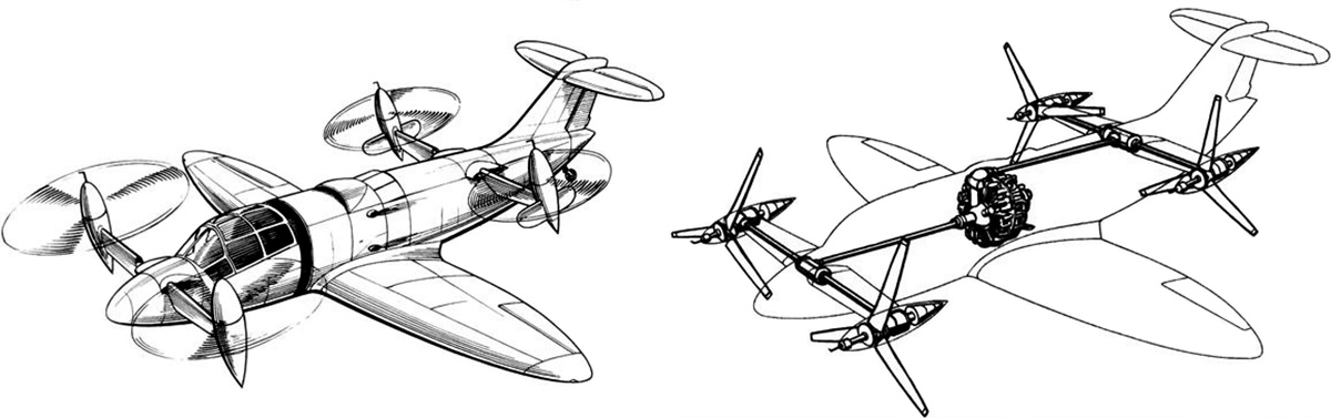
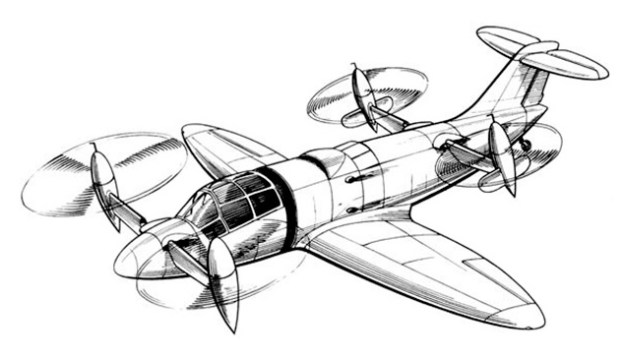
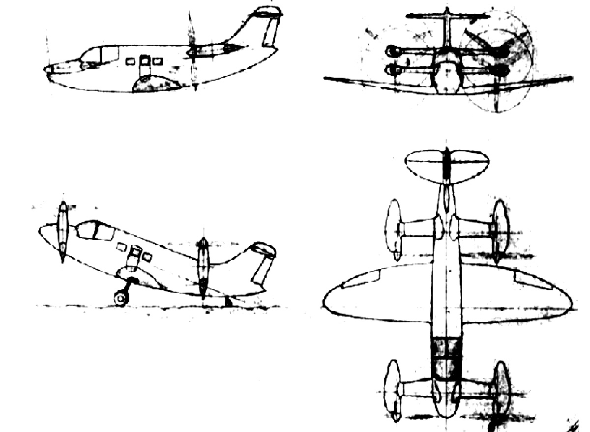
Drawings of how the completed HC-Ib was anticipated to look reveal a pretty compact aircraft, considering the engine installation and associated shafting. The R-3350 engine took up the space intended for a passenger compartment in the Double Mamba-powered HC-I. The Double Mamba would have been installed aft of the passenger compartment.

Immediately following World War II, Germany was prohibited from designing and manufacturing aircraft. Post war, Focke assisted with helicopter development in France and worked for a car company in Germany. He also spent some time in the Netherlands, where he began to design a VTOL aircraft that was capable of relatively high speeds. In 1952, Focke was recruited by the CTA (Centro Técnico de Aeronáutica or Technical Center of Aeronautics) to work in the recently established ITA (Instituto Técnico de Aeronáutica or Technical Institute of Aeronautics). The ITA was the first of four institutes formed by the CTA, all of which were located in São José dos Campos, Brazil. Brazil was working on building an aeronautics and aerospace industry and was actively recruiting German engineers. In addition to Focke, many of his associates and former co-workers were also recruited.

The CTA was impressed with Focke’s VTOL aircraft design and approved its construction. The CTA believed that the aircraft’s capabilities would allow it to reach remote parts of Brazil. Focke set to work on the aircraft—a tiltrotor convertiplane design that was partially inspired by the Fa 269. The aircraft was known as the Heliconair HC-I Convertiplano. Its fuselage and wings were fairly conventional for an aircraft, but it had of two sets of rotors. One pair of rotors was placed near the nose of the aircraft, and the other pair was placed between the wings and tail. All of the rotors were of a tractor configuration and rotated up for vertical flight. The HC-I accommodated two pilots in the cockpit and four passengers in the fuselage. The aircraft’s estimated performance included a top speed of 311 mph (500 km/h) and a range of 943 miles (1,517 km).

CTA - ITA Convertiplano engine test rig

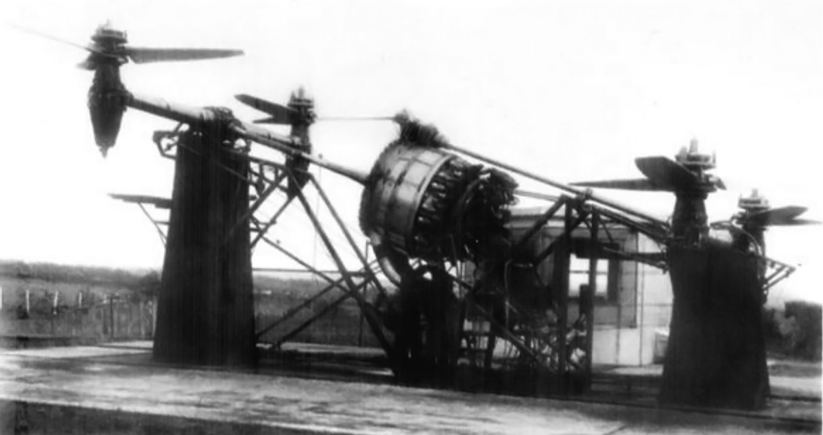
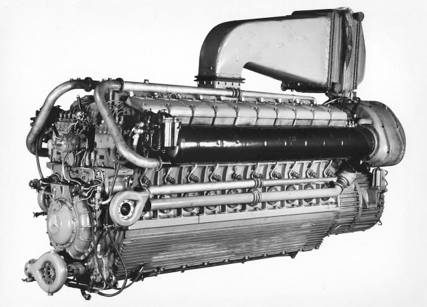
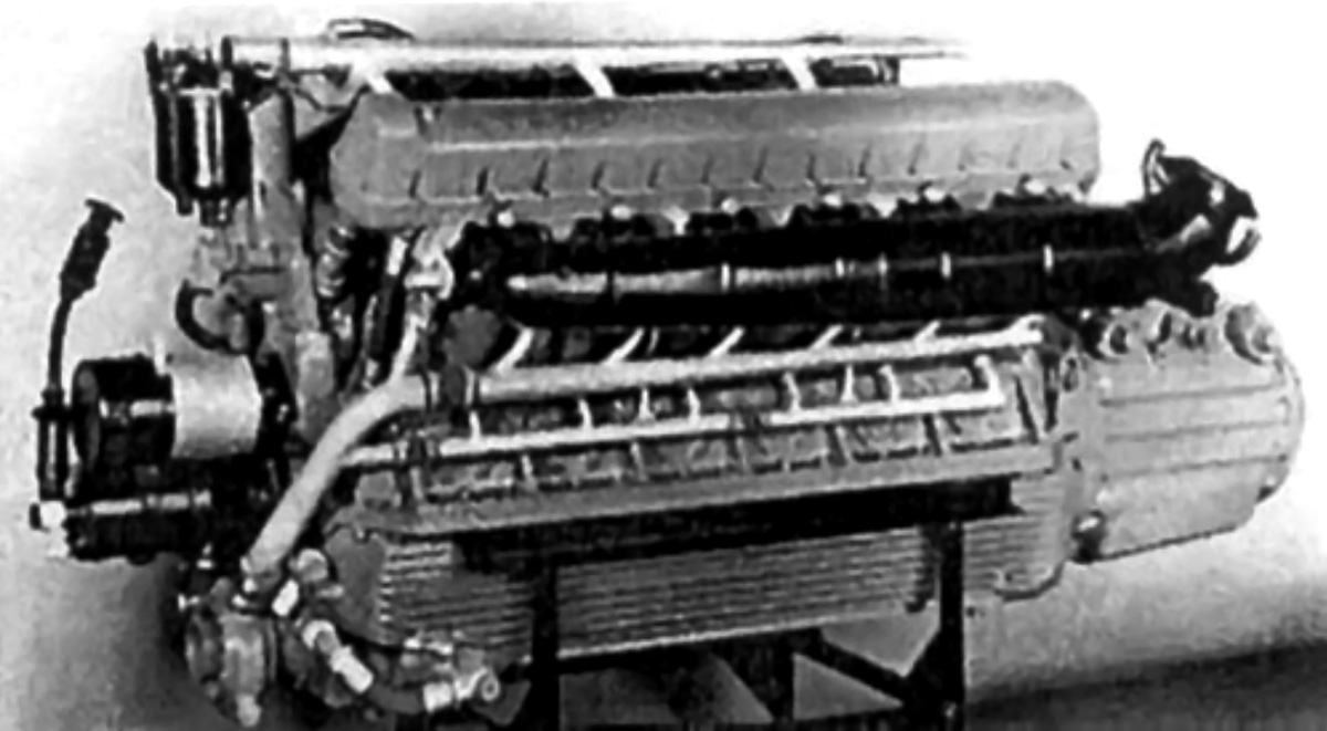
The test rig for the engine, transmission, gearboxes, shafts, right-angle drives, and rotors illustrates the complexity of the HC-Ib’s power system. The R-3350 engine did not have any Power Recovery Turbines, which means it was not a Turbo Compound engine.

To save time and money, the decision was made to build the HC-I using the wings and the horizontal stabilizer from a Supermarine Spitfire. A Spitfire XIVe (RM874) was purchased without its Rolls-Royce Griffon 65 engine from Britain by the Brazilian Air Attaché on 19 December 1952. A new fuselage was built to house a 3,000 hp (2,237 kW) Armstrong Siddeley Double Mamba turboprop engine behind the passenger compartment. However, Armstrong Siddeley and the British did not want one of their new, advanced engines being used in such a radical project and declined selling a Double Mamba engine to Brazil.

Focke and the Convertiplano team changed the HC-I’s design to accommodate a 2,200 hp (1,641 kW) Wright R-3350 radial engine and redesignated the aircraft HC-Ib. The R-3350 was larger and heavier than the Double Mamba, and it produced less power. Some sources state a Turbo Compound R-3350-DA3 (3,250 hp / 2,424 kW) was used, but images show that there are no Power Recovery Turbines on the engine installed in a test rig. Extensive modifications to the aircraft’s fuselage were required to accommodate the air-cooled engine. The passenger compartment was omitted, and the R-3350 was installed in the middle of the fuselage. An annular slit behind the cockpit was added to bring in cooling air for the engine. After passing through the engine’s cylinders, the air exited via a jet-like duct at the rear of the aircraft. The Spitfire’s landing gear was strengthened to compensate for the R-3350’s weight.

CTA - ITA Convertiplano components

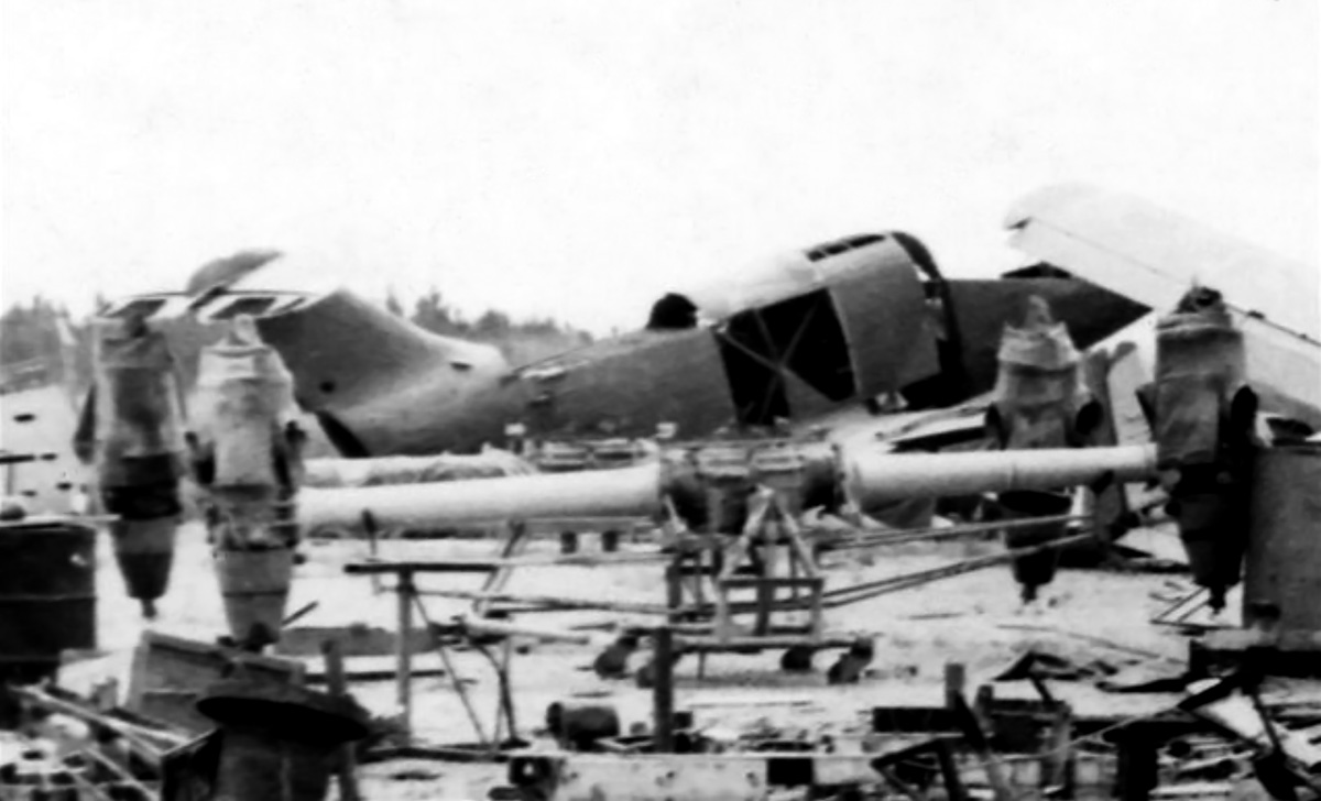
The HC-Ib sits in the background with the front and rear gearboxes and rotor drives in the foreground. The rotor blades, the only surviving component of the Convertiplano project, are not seen in the image. Note the opening at the rear of the fuselage, which was the exit for engine cooling air.

A gearbox transmission mounted to the front of the R-3350 split the engine’s power to two shafts. The front shaft extended from the engine to the front gearbox. The front gearbox had shafts that extended to the left and right. These shafts led to right-angle gearboxes that powered the front rotors. Power delivery for the rear rotors was more complex. A shaft extended vertically from the transmission on the front of the engine and met a right-angle gearbox positioned directly above the engine. From the right-angle gearbox, a shaft extended back to the rear gearbox. The rear gearbox had the same shafts and right-angle drives for the rear rotors as the front gearbox. The transmission and gearboxes were designed by Willi Bussmann and built by BMW in Germany. Bussmann was a former BMW employee and had worked with Focke on several Focke-Achgelis projects.

Each rotor consisted of three blades. The blades were built in Sweden and made of a steel frame that was covered with wood. The blades’ pitch automatically adjusted and had collective and cyclic control. The rotors were counter-rotating, with the right rotors turning counterclockwise and the left rotors turning clockwise. The HC-Ib had a 37 ft 6 in (11.42 m) wingspan and was 35 ft 3 in (10.74 m) long.

CTA - ITA Convertiplano engine hoist

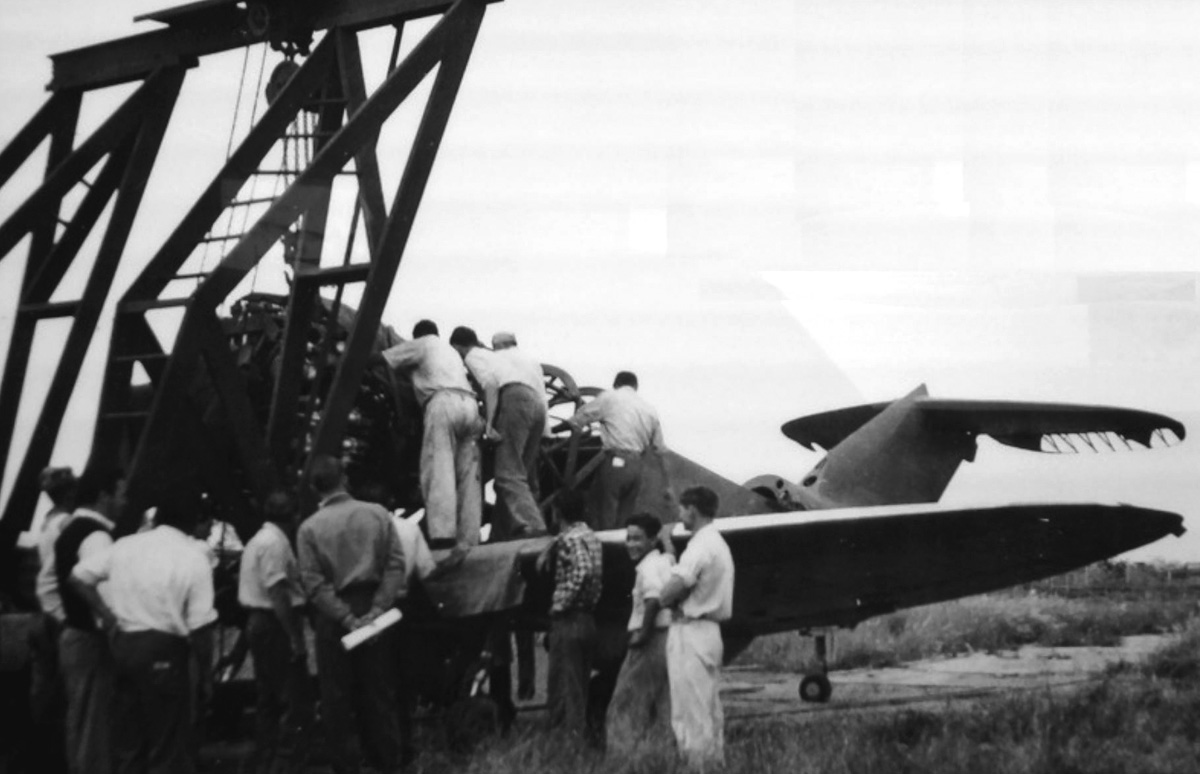
Given the state of the aircraft and the surrounding unchecked growth of vegetation, it can be assumed this image is of the R-3350 engine being removed sometime after the HC-Ib project was cancelled. The image does give proof that the engine was installed in the airframe at one point.

A rig was built, and tests of the engine, gearboxes, shafts, right-angle drives, and rotors began in late 1953. However, vibrations from the radial engine caused some issues that took time to resolve. The HC-Ib airframe was almost completely constructed and had its engine installed when the project was cancelled in 1955. The aircraft was more expensive than anticipated, and interest in the HC-1b had steadily declined after the switch to the R-3350 engine. To make matters worse, many of the Germans returned to Europe or went to the United States as their contracts with the CTA expired. Some Germans did stay and ultimately became part of Embraer. After the project was cancelled, the HC-Ib Convertiplano was left to rot in outside storage for some time and was eventually scrapped in the 1970s. There are some reports that the rotor blades are the only part of the aircraft that survived.

A follow up Convertiplano project was considered. Designated HC-II, the aircraft would be powered by four 1,400 hp General Electric T58 turboshaft engines and reincorporate a four to six passenger cabin. The HC-II never progressed beyond the initial design phase.

CTA - ITA Convertiplano HC-II

The C-II Convertiplano had a GE T58 engine mounted directly to each of its four rotors. Otherwise, it retained the configuration of the original HC-I.

Sources:
Axis Aircraft in Latin America by Amaru Tincopa and Santiago Rivas (2016)
– “Uma Breve História das Atividades do Prof. Focke no Brasil” by Joseph Kovacs, ABCM Engenharia Volume 9 Número 2 (April–September 2003)
http://www.internationalresinmodellers.com/articles_15_cta_heliconair_hc-i_-ii_convertiplano
http://aeromagazine.uol.com.br/artigo/convertiplano-o-pioneiro-esquecido_491.html
https://en.wikipedia.org/wiki/Henrich_Focke
https://en.wikipedia.org/wiki/Focke-Wulf
http://allspitfirepilots.org/aircraft/RM874
http://www.secretprojects.co.uk/forum/index.php?topic=25141.0
http://forum.keypublishing.com/showthread.php?24794-Mark12-s-Quiz&s=17aba5b94d69d4e1642b3d04aefcf85c

mercedes-benz-mb-518-v-20-rear

Mercedes-Benz 500 Series Diesel Marine Engines

By William Pearce

Daimler-Benz was formed in 1926 with the merger of Daimler Motoren Gesellschaft and Benz & Cie. Prior to their merger, both companies produced aircraft engines under the respective names Mercedes and Benz. After the merger, the Daimler-Benz name was used mostly for aircraft engines, and the Mercedes-Benz name was used mostly for automobile production. However, both names were regularly applied to marine engines. For clarity in this article, the name Daimler-Benz will refer to aircraft engines, and the name Mercedes-Benz will refer to marine engines.

mercedes-benz-mb-501-v-20-rear

The MB 501 shows the close family resemblance to the DB 602, but the engines had Vees of different angles and completely different valve trains. The tubes for the pushrods can be seen on the outer side of the cylinders. Note the two water pumps on the rear sides of the engine.

As Germany began its rearmament campaign in the 1930s, high-performance marine diesel engines were needed to power various motorboats. The Kriegsmarine (German Navy) turned to Mercedes-Benz to supply a series of high-speed diesel engines. These engines were part of the MB 500 series of engines that were based on the Daimler-Benz DB 602 (LOF-2) engine developed to power the LZ 129 Hindenburg and LZ 130 Graf Zeppelin II airships. The 500 series diesel engines were four-stroke, water-cooled, and utilized a “V” cylinder arrangement.

The first engine in the 500 series was the MB 500 V-12. The engine’s two cylinder banks were separated by 60 degrees. The MB 500 used individual steel cylinders that were attached to an aluminum alloy crankcase. About a third of the cylinder was above the crankcase, and the remaining two-thirds protruded into the crankcase. This arrangement helped eliminate lateral movement of the cylinders and decreased vibrations. The crankcase was made of two pieces and split horizontally through the crankshaft plane. The lower part of the crankcase was finned to increase its rigidity and help cool the engine oil.

mercedes-benz-mb-501-v-20-crackington

The crankcases of the wrecked MB 501 engines on Crackington Haven Beach have completely dissolved over the years from constant exposure to salt water. Only the engine’s steel components remain. Note the fork-and-blade connecting rods. The engine’s gear reduction can be seen on the left side of the image. (gsexr image via 350z-uk.com)

Each cylinder had two intake and two exhaust valves. The camshaft had two sets of intake and exhaust lobes per cylinder. One set was for normal operation, and the other set was for running the engine in reverse. The fore and aft movement of the camshaft to engage and disengage reverse operation was pneumatically controlled. Bosch fuel injection pumps were located at the rear of the engine and were geared to the camshaft. Each injection pump provided fuel to the cylinders at 1,600 psi (110.3 bar). Fuel was injected into the center of the pre-combustion chamber, which was in the center of the cylinder head and between the four valves. For low-speed operation, fuel was cut from one bank of cylinders.

The MB 500 had a compression ratio of 16.0 to 1. The engine used fork-and-blade connecting rods that rode on roller bearings fitted to the crankshaft. The camshaft also used roller bearings, but the crankshaft was supported by plain bearings. Speed reduction of the engine’s output shaft was achieved through the use of bevel planetary gears. Two water pumps mounted to the rear sides of the engine circulated water through the cylinder banks. Each pump provided cooling water to one cylinder bank. The pumps were driven by a cross shaft at the rear of the engine. The engine was started with compressed air.

mercedes-benz-mb-502-v-16

With the exception of the different intake manifolds, the MB 502 was nearly identical to the DB 602. Note the Mercedes-Benz emblem on the rear of the V-16 engine.

The MB 500 had a 6.89 in (175 mm) bore and a 9.06 in (230 mm) stroke. This cylinder size directly corresponded to the cylinder size used on the DB 602. The MB 500’s displacement was 4,051 cu in (66.39 L). The engine had a continuous output of 700 hp (522 kW) at 1,460 rpm and a maximum output of 950 hp (708 kW) at 1,630 rpm. Fuel consumption was .397 lb/hp/hr (241 g/kW/hr). The MB 500 was 9.6 ft (2.93 m) long, 3.2 ft (.98 m) wide, and 5.7 ft (1.73 m) tall. The engine weighed around 4,784 lb (2,170 kg). MB 500 engines were installed in Schnellboote that Germany built for Bulgaria. A Schnellboot, or S-boot, was a fast attack boat and was referred to as an E-boat (Enemy boat) by the Allies.

For more power, the MB 501 was built with two rows of ten cylinders, creating a V-20 engine. The MB 501 was similar to the MB 500, but it also had a number of differences. A 40 degree angle separated the cylinder banks, and a second set of fuel injection pumps was driven from the front of the engine. The MB 501 used two camshafts positioned in the upper crankcase, one on each side of the engine. Rollers on the lower end of the pushrods rode on the camshaft. Two pushrods for each cylinder extended up along the outer side of the cylinder bank to operate a set of duplex rocker arms for the two intake and two exhaust valves. The fork-and-blade connecting rods were attached to the crankshaft with plain bearings.

mercedes-benz-mb-507-v-12

The MB 507 was based on the DB 603 inverted V-12 aircraft engine. Although the engine’s architecture was similar, the MB 507 had a completely different crankcase and reduction gear than the DB 603, and it was not supercharged.

The MB 501’s bore and stroke were increased over the MB 500’s to 7.28 in (185 mm) and 9.84 in (250 mm) respectively. The engine displaced 8,202 cu in (134.40 L). The MB 501 had a continuous output of 1,500 hp (1,119 kW) at 1,480 rpm and a maximum output of 2,000 hp (1,491 kW) at 1,630 rpm. Fuel consumption was .397 lb/hp/hr (241 g/kW/hr). The engine was 12.7 ft (3.88 m) long, 5.2 ft (1.58 m) wide, 5.6 ft (1.71 m) tall, and had a weight of 9,303 lb (4,220 kg). Three MB 501 engines were installed in each 1937 class Schnellboot. Six engines were installed in each of the U-180 and U-190 submarines. However, the MB 501 engines proved unsuitable in the submarines, and they were soon replaced by MAN diesels. The remains of three MB 501 engines can be found on Crackington Haven Beach in southeast Britain. The engines belonged to Schnellboot S-89, which was surrendered to the British after World War II. S-89 slipped its tow on 5 October 1946 and was wrecked upon the shore.

The MB 502 was essentially a Daimler-Benz DB 602, except it had water jacketed intake manifolds that protruded above the engine’s Vee. The rest of the MB 502’s specifics mirrored those of the DB 602. The MB 502 was a 50 degree V-16 with a single camshaft located in the Vee of the engine. The engine had a 6.89 in (175 mm) bore and a 9.06 in (230 mm) stroke. The MB 502 displaced 5,401 cu in (88.51 L) and had a continuous output of 900 hp (671 kW) at 1,500 rpm and a maximum output of 1,320 hp (984 kW) at 1,650 rpm. The engine was 9.9 ft (3.02 m) long, 4.0 ft (1.22 m) wide, and 6.2 ft (1.90 m) tall. The MB 502 weighed 5,952 lb (2,700 kg) and had a fuel consumption at cruising power of 0.37 lb/hp/hr (225 g/kW/hr). Three MB 502 engines were installed in each 1939 class Schnellboot.

mercedes-benz-mb-511-v-20-aeronauticum

The MB 511 engine on display in the Aeronauticum museum in Germany. Note the finning on the lower half of the crankcase. On the front of the engine (left side of image) is the gear reduction with the supercharger above. The square connection above the engine is for the induction pipe. (Teta pk image via Wikimedia Commons)

The MB 507 was based on the Daimler-Benz DB 603 inverted V-12 aircraft engine, but some features from the DB 602 were incorporated. The normally aspirated MB 507 was an upright V-12 diesel engine that used monobloc cylinders and had a compression ratio of 17 to 1. A new finned crankcase was fitted that was similar to those used on other MB 500 series diesel engines. For the initial MB 507 engines, the bore was decreased from the 6.38 in (162 mm) used on the DB 603 to 6.22 in (158 mm). The stroke was unchanged at 7.09 in (180 mm). This gave the MB 507 a displacement of 2,584 cu in (42.35 L). The DB507 weighed 1,834 lb (850 kg). The engine had a continuous output of 700 hp (522 kW) and a maximum output of 850 hp (634 kW) at 2,300 rpm. An updated version of the engine, the MB 507 C, reverted back to the 6.38 in (162 mm) bore, which increased its displacement to 2,717 cu in (44.52 L). The MB 507 C produced 750 hp at 1,950 rpm and 1,000 hp at 2,400 rpm. The engine was 6.0 ft (1.83 m) long, 2.6 ft (.79 m) wide, 3.5 ft (1.06 m) tall, and had a weight of 1,742 lb (790 kg). Two MB 507 engines were used in a few LS boats (Leicht Schnellboot or Light Fast boat), and the engine was also installed in some land vehicles, such as the Karl-Gerät self-propelled mortar.

The MB 511 was a supercharged version of the MB 501 V-20 engine. The bore, stroke, and displacement were unchanged, but the compression ratio was decreased to 14 to 1. The supercharger was positioned at the front of the engine, above the gear reduction. With the supercharger, output increased to 1,875 hp (1,398 kW) at 1,480 rpm for continuous power and 2,500 hp (1,864 kW) at 1,630 rpm for maximum power. The MB 511 was 13.1 ft (4.00 m) long, 5.2 ft (1.58 m) wide, and 7.6 ft (2.33 m) tall. The engine weighed 10,406 lb (4,720 kg). Three MB 511 engines were installed in each 1939/1940 class Schnellboot. An MB 511 engine is on display in the Aeronauticum maritime aircraft museum in Nordholz (Wurster Nordseeküste), Germany. Also, the MB 511 engine was built by VEB Motorenwerk Ludwigsfelde as the 20 KVD 25 in East Germany in the 1950s. Two 20 KVD 25 engines were installed in an experimental torpedo boat.

mercedes-benz-mb-518-v-20-drawings

The sectional and cylinder drawing are for the MB 518 but were basically the same for the MB 501 and MB 511—all were 40 degree V-20 engines with individual cylinders. Note the pre-combustion chamber, valve train, and two camshafts.

The MB 512 was a supercharged version of the MB 502. Its compression was decreased to 14 to 1, but its output increased to 900 hp (1,398 kW) at 1,500 rpm for continuous power and 1,600 hp (1,864 kW) at 1,650 rpm for maximum power. The MB 512 was 10.0 ft (3.05 m) long, 4.2 ft (1.28 m) wide, and 6.3 ft (1.92 m) tall. The engine weighed 6,834 lb (3,100 kg). MB 512 engines replaced MB 502s in some Schnellboot installations.

The MB 517 diesel engine was a supercharged version of the MB 507. Returning to its DB 603 roots, the engine was inverted, but it retained the 6.22 in (158 mm) bore and 7.09 in (180 mm) stroke of the early MB 507. The supercharger boosted power from the 2,584 cu in (42.35 L) engine to 1,200 hp (895 kW) at 2,400 rpm. The MB 517 was installed in the Panzer VIII Maus V2 tank prototype.

mercedes-benz-mb-518-v-20-rear

The MB 518 was the last development of the V-20 engines. This image shows the large intercooler installed on the engine’s induction system.

The MB 518 was a continuation of the MB 511 and featured an intercooler. The large intercooler was positioned in the intake duct, above the engine and between the supercharger at the front of the engine and the intake manifolds in the engine’s Vee. The first MB 518s had a continuous output of 2,000 hp (1,696 kW) at 1,500 rpm and a maximum output of 3,000 hp (2,237 kW) at 1,720 rpm. After World War II, updated versions of the engine went into production starting in 1951. The MB 518 B had a continuous output of 2,275 hp (1,696 kW) and a maximum output of 3,000 hp (2,237 kW). The MB 518 C had a continuous output of 2,500 hp (1,864 kW) and a maximum output of 3,000 hp (2,237 kW). A turbocharger was added to create the MB 518 D. It had a continuous output of 2,900 hp (2,163 kW) and a maximum output of 3,500 hp (2,610 kW). The MB 518 engine was 14.8 ft (4.52 m) long, 5.2 ft (1.58 m) wide, and 8.0 ft (2.44 m) tall. The engine weighed around 11,332 lb (5,140 kg). MB 518 engines were used to power several different vessels for the German Navy and were also exported to 35 countries. Some of the engines are still in use today.

Schnellboot S-130, the only remaining German S-boot from World War II, was originally powered by three MB 511 engines. After the war, S-130 was reengined with two MB 518s, and one MB 511 was retained. S-130 is currently part of the Wheatcroft Collection and undergoing restoration. Four MB 518 C engines for the restoration were obtained from the Arthur of San Lorenzo, formerly known as the S39 Puma and originally built as a German Zobel Class fast patrol boat in the early 1960s.

mercedes-benz-mb-518-v-20-assembly

A number of MB 518 engines under construction show many different details. The lower crankcase half is on the floor, while the upper half is in the engine cradle; note the two camshaft tunnels. The crankshaft and its fork-and-blade connecting rods can be seen. Farther down the line is an engine with cylinder studs installed, and farther still is an engine with studs and pushrod tubes installed.

Sources:
http://alternathistory.com/dvigateli-nemetskikh-torpednykh-katerov-razrabatyvavshiesya-i-seriino-stroivshiesya-v-1920-1940-gody
https://de.wikipedia.org/wiki/Mercedes-Benz_MB_518
http://ftr.wot-news.com/2014/11/25/maus-engine-by-captiannemo/
https://ww2aircraft.net/forum/threads/opportunity-lost-db-16-cyl.21836/
http://www.german-navy.de/kriegsmarine/ships/fastattack/schnellboot1937/tech.html
http://www.german-navy.de/kriegsmarine/ships/fastattack/schnellboot1939/tech.html
http://www.german-navy.de/kriegsmarine/ships/fastattack/schnellboot1940/tech.html
http://www.wrecksite.eu/wreck.aspx?163703
http://www.shipspotting.com/gallery/photo.php?lid=1885985
http://s-boot.net/sboats-vm-forelle.html