

By William Pearce
John Godfrey Parry Thomas was a British engineer and was widely known as Parry Thomas. During World War I, Thomas was a member of the Munitions Invention Board and was brought on as the chief engineer at Leyland Motors in 1917 to help the firm develop an aircraft engine.
Allan Ferguson had been working at Leyland on the design of the aircraft engine. The engine Ferguson had designed was a 450 hp (336 kW), water-cooled W-18 with banks set at 40 degrees. Each bank consisted of two three-cylinder blocks, and there were plans to make a W-9 engine with just three banks of three cylinders. Long pushrods extended from camshafts in the crankcase between the cylinder banks to the top of the cylinders to actuate the overhead valves. Thomas felt that the W-18 engine would not be successful and proposed his own design, which won the approval of Leyland management.

The Thomas (Leyland) X-8 engine was made from aluminum and had many interesting features. At the rear of the engine, the handle is attached to a dynamo for starting. Just above the dynamo is the crankshaft-driven water pump. The engine’s carburetors are mounted on either side of the water pump. Note the integral passageways leading from the carburetor to the cylinders. The oil sump tank is positioned in the lower engine Vee.
Assisted by Fred Sumner and Reid Railton, Thomas’ engine design was an X-8 with cylinder banks spaced at 90 degrees. Each cylinder bank consisted of two paired cylinders. The cylinder banks were cast integral with the aluminum crankcase, and nickel-chrome cylinder wet liners were heat-shrunk into the cylinder banks. An aluminum cylinder head was attached to each cylinder bank via eight bolts. A propeller gear reduction was incorporated into the engine. The gear reduction used bevel gears and reduced the propeller speed to .50 times crankshaft speed. The gear reduction kept the propeller position in line with the crankshaft.
A single overhead camshaft operated the two intake and two exhaust valves for each cylinder. The camshaft was driven via a vertical shaft at the rear of the engine. The valves were closed by leaf springs. Via adjustable screws, one end of a leaf spring was attached to an intake valve while the other end of the spring was attached to an exhaust valve. The springs were allowed to articulate at their mounting point so that as one valve was opened, additional tension was applied to the closed valve for an even tighter seal.
Two carburetors were positioned at the rear of the engine, with each carburetor providing the air/fuel mixture for one side of the engine. Each carburetor was mounted to an integral intake passageway in the crankcase, with four individual ducts branching off from the passageway. Each duct connected one cylinder to the intake passageway. Exhaust was expelled from the upper and lower engine Vees. Each cylinder had two spark plugs fired by either a magneto or battery ignition.
A water pump driven at the rear of the engine by the crankshaft circulated water through the engine at around 48 gpm (182 L). The coolant flowed into the cylinder banks and around the exhaust ports to keep the exhaust valves cool. A pipe system enabled water to flow through the hollow crankshaft at 10 gpm (36 L), cooling the three main bearings and two connecting rod bearings. The water also cooled the oil that flowed through the crankshaft and to the bearings. To further cool the oil, the water and oil flowed into the propeller gear reduction, where the oil passed along the finned outer side of the water-cooled propeller shaft.
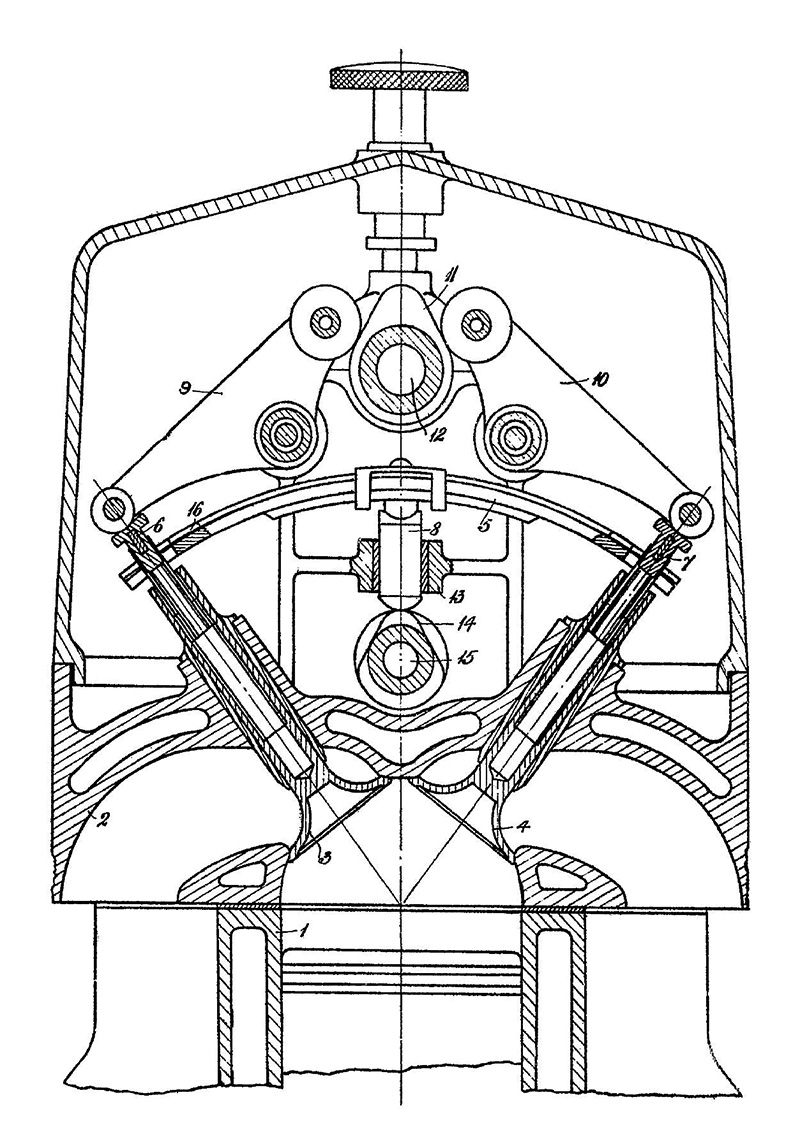
While not of the X-8 engine, this drawing does depict the leaf spring valves, similar to the setup used in the X-8 engine. The leaf spring (5) held the valves (3 and 4) closed. Lobes (11) on the camshaft (12) acted on the rockers (9 and 10) to open the valves. The leaf spring mount (8) could move up and down to add tension on the closed valve for a tighter seal. (GB patent 216,607, granted 5 June 1924)
Attached to each of the crankshaft’s two crankpins was a master connecting rod, and three articulated rods were attached to each master rod. The crankshaft had both of its crankpins inline, which meant that the pistons for one cylinder bank would both be at top dead center at the same time. One source states that the crankpins were in the same phase, meaning the two cylinders of the same bank would be on the same stroke, essentially making the X-8 engine operate like two synchronized X-4 engines. This was reportedly done to prevent any rocking motion created by the front X-4 firing followed by a rear X-4-cylinder firing 90 degrees later. However, a different source says the cylinders were phased 360 degrees apart, which would make more sense. While the pistons of one cylinder bank were both at top dead center, one cylinder was starting the intake stroke while the other was starting the power stroke. The 360-degree phasing would create a rather smooth firing order, such as bank 1 front cylinder (1F), bank 2 rear cylinder (2R), 3F, 4R, 1R, 2F, 3R, and 4F. However, the engine’s true firing order is not known.
A dry-sump lubrication system was used. Oil from the engine was collected in a one gallon (4.5 L) tank mounted in the lower engine Vee. The oil was then returned to a main oil tank of approximately eight gallons (32 L) installed in the aircraft. For starting, the X-8 engine used an electric starter motor or a hand-cranked dynamo. The engine incorporated an interrupter gear for firing guns through the propeller arc.
The X-8 engine had a 6.0 in (152 mm) bore and a 4.5 in (114 mm) stroke. The engine displaced 1,018 cu in (16.7 L) and produced 300 hp (224 kW) at 2,500 rpm and 10,000 ft (3,048 m). Maximum engine speed was around 3,500 rpm. The X-8 engine weighed around 500 lb (227 kg). For the time, 500 lb (227 kg) was remarkably light for a 300 hp (224 kW) engine. The X-8 was noted as being very compact, but a list of engine dimensions has not been found.
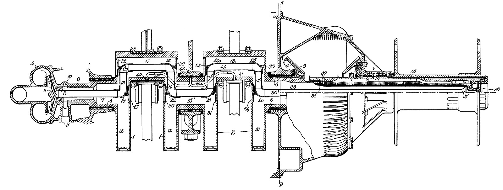
Patent drawing of the X-8’s crankshaft with its inline crankpins. The water pump (4) housed the crankshaft-driven impeller (9). Water was pumped through an inlet (11), through a passageway (10), and into the pipe built-up in the hollow crankshaft. The water then flowed through the propeller shaft (36) to cool oil in an adjacent passageway (45).
The design of the Thomas X-8 was completed in December 1917 and submitted to the Air Ministry. Thomas initiated an extensive part-testing program that resulted in the creation of numerous test fixtures. In conjunction with the test-fixtures, A single-cylinder test engine was built and tested in 1918. The single-cylinder produced 37 hp (28 kW) at 2,500 rpm and 53 hp (40 kW) at 3,700 rpm. These outputs equated to 296 hp (221 kW) and 424 hp (316 kW) respectively for the complete eight-cylinder engine. However, the piston in the single-cylinder engine failed after five minutes of running between 3,500 and 3,700 rpm.
A complete X-8 engine was built and run for the first time in August 1918. Compression ratios of 5.8 and 6.3 were used on the single-cylinder engine, but the compression ratio of the complete engine has not been found. Reportedly, the engine was hastily assembled because government inspectors wanted the test two weeks earlier than planned. The X-8 engine’s lightly-built crankcase deformed and closed in the crankshaft bearing clearance, resulting in the engine seizing after a few hours of running.
With the end of World War I on 11 November 1918, further work on the Thomas X-8 engine was abandoned. A number of features from the aircraft engine were later used on the Leyland automotive straight-eight engine developed in 1920. Thomas went on to become a legend at the Brooklands Raceway, campaign one of the first aero-engined Land Speed Record (LSR) monster cars, and set a flying-mile (1.6 km) LSR of 170.624 mph (274.593 km/h) on 28 April 1926. Thomas tragically died in a crash attempting another LSR on 3 March 1927. His death marked the first time a driver was killed while in direct pursuit of a LSR.

Thomas behind the wheel of his Leyland-Thomas racer at Brooklands on 4 October 1926. (Getty image)
Sources:
– “AIR: Parry Thomas’s Aero-Engine” by William Boddy, Motor Sport (February 1995)
– “The Life Story of Parry-Thomas” by Fred Sumner, Motor Sport (November 1941)
– “Internal Combustion Engine,” US patent 1,346,280 by John Godfrey Parry Thomas (granted 13 July 1920)
– Reid Railton: Man of Speed by Karl Ludvigsen (2018)
– Parry Thomas by Hugh Tours (1959)

I really love these posts, particularly the pre-war/ early British engines.
One problem that I seem to repeatedly have is that the first image on every post is a black square. Anyone else have these issues?
I’m glad you like the articles and am sorry to hear of the first image. Very odd. I have not experienced anything like that. If you refresh the page, does the image come up?
What a unique engine! Bill, can you elaborate on the action of 8, 13,14,& 15? It appears the fulcrum of the leaf spring sits on a cylindrical cam follower that is driven by its own cam to raise and lower the pivot height. It seems the follower is at its maximum height whenever both valves are closed (for max closing pressure), but then fulcrum is lowered when one or the other of the valves is to be opened, reducing the pressure to open the valve being actuated while maintaining the “closed” pressure on the opposing valve. I’m guessing the fulcrum cam runs the same speed as the overhead cam. Just fantastic. Thanks.
Hello Tom,
I have added the patent for the valve (linked in caption), which is not the exact one used on the X-8 engine but a later variant used on the Leyland Eight engine circa 1920. You are correct on its operation. Paraphrased, the patent states: abutment 8 is made moveable in guide 13, and it is oscillated in correspondence with the movements of the levers 9, 10 by cam 14 on an auxiliary camshaft 15. Cam 14 is shaped to allow the spring abutment 8 to fall twice during each revolution, when cam 12 is operating lever 9 and lever 10 respectively. Between those times, the cam 14 closes the valves by lifting the abutment 8. By suitable design of the profile of the cams 12 and 14, variation in the stress on spring 5 may be avoided…. The spring ought always to be under some stress to keep the valves firmly on the seating when closed; and generally, the cam 14 will be so shaped as to close the valve slightly before its part of maximum diameter contacts with the abutment upon it, the remaining motion serving to stress the spring to give a tight closure.
Thanks for that! TF
That valve spring idea is interesting, like a poor man’s desmodromic action . reducing load on the cam yet providing sufficient force to accelerate the valve to closure .
Happy New Year
Bill Todd
The oval shape of the ports suggest four valves per cylinder. ?
Correct! Two intake and two exhaust valves per cylinder.
I need new glasses !