By William Pearce
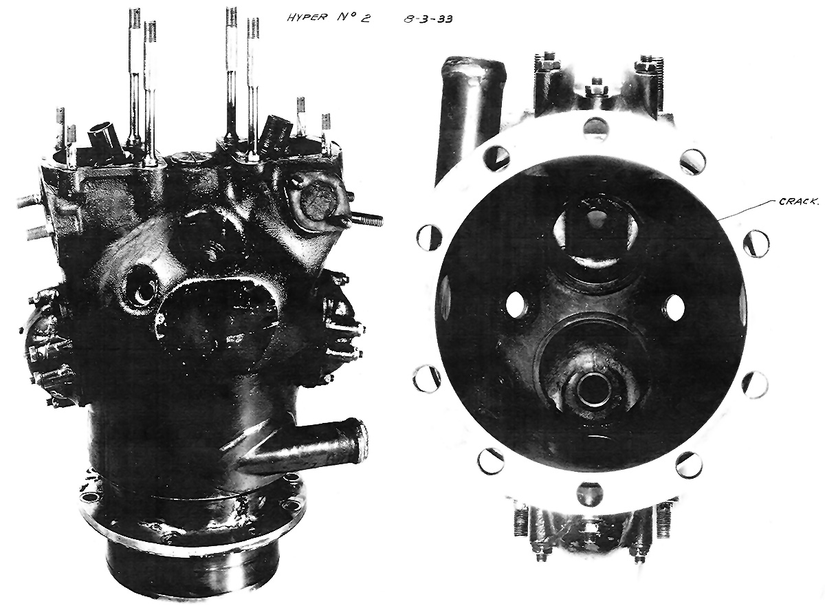
In 1932, the Army Air Corps (AAC) contracted the Continental Motors Company to develop a high-performance (Hyper) cylinder that would produce 1 hp per cu in (.7 kW per 16 cc). Based on promising test results, an order was placed for a 1,000 hp (746 kW), 12-cylinder O-1430 aircraft engine. The AAC had stipulated that the engine needed to be a horizontally opposed (flat) configuration and use individual cylinders. Lengthy delays were encountered with development of the Hyper No. 2 cylinder, and the situation was made worse by Continental’s financial state. Continental did not fund much of the project, and each change and every purchase was sent to the AAC for contractual approval.
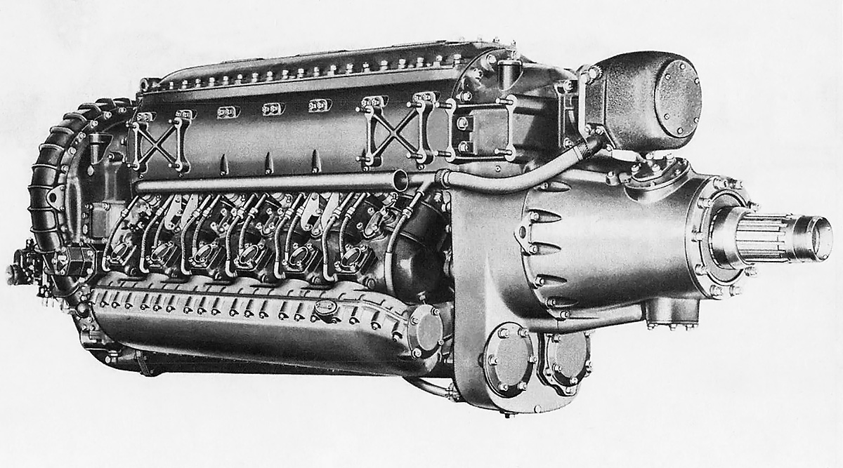
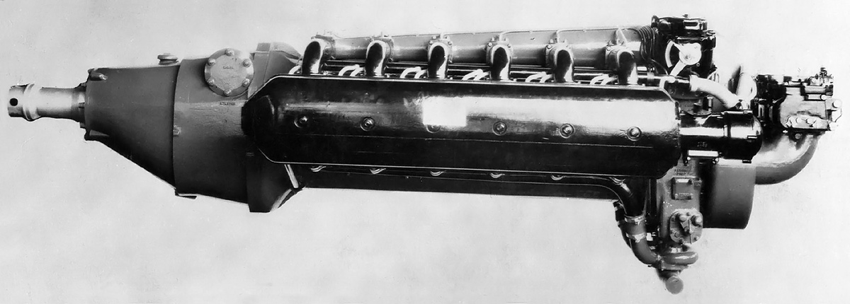
The Continental XI-1430 was a compact, high-performance aircraft engine capable of producing an impressive amount of power but also suffered from reliability issues. The mounting pads on the front accessory case, below the nose case, were for the starter and generator.
The O-1430 was finally completed and run in 1938. While it did meet the 1,000 hp (746 kW) goal, the six years of development rendered the engine obsolete. The Allison V-1710 and the Rolls-Royce Merlin had already passed the 1,000 hp (746 kW) mark years previously. However, the AAC and Continental believed that the engine could be reworked to produce 1,600 hp (1,193 kW). In 1939, the AAC requested that Continental use the O-1430 as the basis for an inverted Vee engine designated XI-1430. Especially early on, the engine was also referred to as the XIV-1430 or IV-1430. The XI-1430 would keep the basic individual cylinders of the O-1430, but the cooling requirement was changed from 300° F (149° C) to 250° F (121° C). The Vee configuration (even if inverted) and 250° F (121° C) coolant were preferred by Continental from the start. To speed development of the engine, Continental agreed to put at least $250,000 of its own money toward the project and was willing to proceed based on verbal agreements with the AAC rather than waiting for changes to be specified in writing.
In 1940, Continental Motors Company created a subsidiary known as Continental Aviation and Engineering Corporation to develop aircraft engines of over 500 hp (373 kW). Most of the XI-1430 development was done under the Continental Aviation and Engineering Corporation. The XI-1430 was essentially a new engine with perhaps just the pistons, connecting rods, and a few other parts being interchangeable with the earlier O-1430.
The XI-1430 had a one-piece aluminum crankcase. The crankshaft was supported by seven main bearings and secured to the crankcase by bearing caps. A cover plate sealed the top of the inverted crankcase. Two banks of six individual cylinders were secured to the crankcase via studs. The cylinder banks had an included angle of 60 degrees. The pistons were attached to the crankshaft via fork-and-blade connecting rods. When viewed from the rear, the blade rods served the left bank, and the fork rods served the right bank.

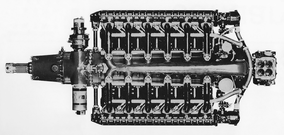
The gear train of a clockwise-turning (right-handed) XI-1430-9. Unlike with the O-1430 in which a few gears could be swapped for clockwise vs counterclockwise rotation, the XI-1430 had a different gear train that incorporated various idler gears for counterclockwise rotation.
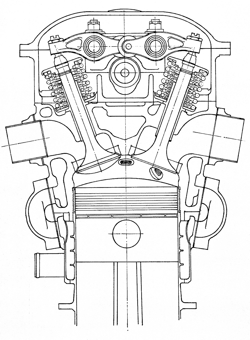
The cylinders used the same bore and stroke as the Hyper No. 2 test cylinder and the O-1430. While their design was similar to the previous applications, the XI-1430’s cylinders had been further refined. Each cylinder was made up of a forged steel barrel screwed and shrunk into a forged aluminum cylinder head. The new cylinder head was more compact than that used previously. A steel water jacket surrounded the cylinder barrel and was secured to the cylinder head. Two spark plugs were installed in each cylinder, with one by the intake port and the other by the exhaust port. The cylinder had a single intake valve and a single sodium-cooled exhaust valve. Both valves were actuated by a single overhead camshaft located in a housing that bolted atop all the cylinders of a given bank. Each camshaft was driven through bevel gears by a nearly-horizontal shaft at the front of the engine. Various accessories were driven from the rear of the camshaft.
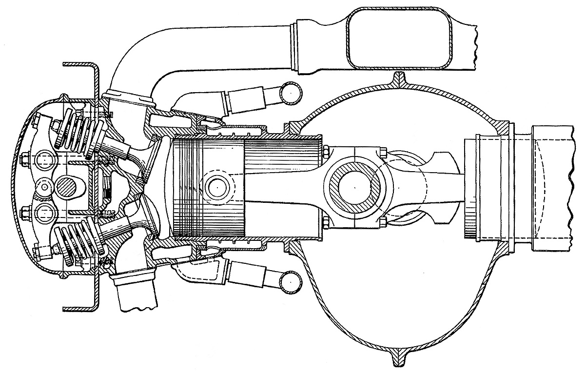
An updraft Stromberg injection carburetor was positioned at the extreme rear of the XI-1430 engine. It fed air and fuel into the single-speed, single-stage supercharger, which was mounted to the rear of the engine. The supercharger impeller was 10.5 in (267 mm) in diameter and turned at 5.928 times crankshaft speed. The supercharger drive case also powered various pumps: oil, water, vacuum, and hydraulic. An intake manifold led from the bottom of the supercharger and extended through the inverted Vee of the engine. Short individual runners branched off the manifold and supplied the air and fuel mixture to each cylinder.
An accessory drive case was mounted to the front of the engine. Driven from the accessory case were the starter, generator, an oil pump, and a single dual-magneto. The magneto was mounted on the upper front of the accessory drive case and fired the two spark plugs in each cylinder. The accessory drive case also housed the spur gears that made up part of the XI-1430’s propeller gear reduction. Mounted to the front of the accessory drive was a nose case that contained a bevel planetary gear reduction that drove the propeller shaft. The speed of the crankshaft was partly reduced via the spur gears in the accessory drive case, then further reduced via the planetary gears in the nose case. This two-stage gear reduction was probably adopted to keep the XI-1430’s frontal area to a minimum and possibly to extended the nose of the engine for a more streamlined installation. Depending on the engine model, the final speed of the propeller shaft was .360, .385, or .439 crankshaft speed.
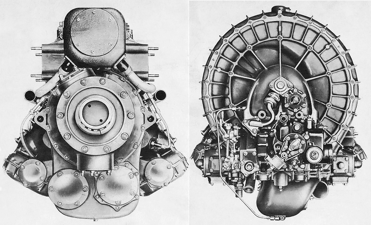
Front and rear views of the XI-1430 illustrate the engine’s rather compact configuration. On the front of the engine, the housings for the camshaft drives can just be seen between the accessory drive and the circular covers on the cylinder banks. Note the size of the supercharger housing on the rear view.
The Continental XI-1430 had a 5.5 in (140 mm) bore and a 5.0 in (127 mm) stroke. The engine displaced 1,425 cu in (23.4 L) and had a compression ratio of 6.5 to 1. XI-1430 installations included a General Electric (GE) turbosupercharger and air-to-air intercooler. The engine initially had a takeoff rating of 1,350 hp (1,007 kW) at 3,300 rpm and a military rating of 1,600 hp (1,193 kW) at 3,200 rpm up to 25,000 ft (7,620 m). Development ultimately increased takeoff power to 1,600 hp (1,193 kW) at 3,300 rpm and 15.3 psi (1.05 bar) of boost. The XI-1430 maintained this power as its normal rating up to 25,000 ft (7,620 m), but at 3,000 rpm. Emergency power was 2,100 hp (1,566 kW) at 3,400 rpm with 28.5 psi (1.97 bar) of boost at 25,000 ft (7,620 m). The XI-1430 was 112.5 in (2.86 m) long, 30.9 in (.78 m) wide, and 33.5 in (.85 m) tall. The engine weighed 1,615 lb (733 kg).
On 20 February 1940, the AAC issued Request for Data R40-C that sought designs of new fighter aircraft capable of 450 mph (724 km/h), with 525 mph (845 km/h) listed as desirable. With a new generation of high-power aircraft engines under development, manufacturers saw it as an opportunity be creative. Five of the 26 submitted designs (some of which only offered slight variations) used the XI-1430 as the selected engine. Bell offered two XI-1430-powered variants of what was similar to a P-39 Airacobra, and two Curtiss-Wright XI-1430-powered submissions were similar to reengined examples of their CW-21 and XP-46. The later design was contracted mid-1940 as the XP-53. However, due to delays with the XI-1430 engine, the AAC requested the substitution of a Packard V-1650 (Merlin) in October 1940, and the XP-53 was subsequently redesignated as the XP-60.
A third XI-1430-powered R40-C proposal from Curtiss-Wright was a pusher aircraft designated P-249C. A design contract for the P-249C was issued on 22 June 1940, but the decision was made not to proceed with a prototype. Curtiss-Wright continued to refine the design and substituted an Allison V-1710 engine (this aircraft design was also an R40-C submission). The V-1710-powered aircraft was eventually built as the XP-55 Ascender. None of XI-1430-powered R40-C aircraft were built.

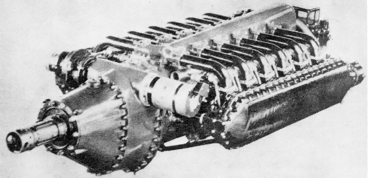
The induction pipe can be seen extended from the bottom of the supercharger housing and to the inverted Vee between the cylinder banks. Note how the camshaft housing was attached to each individual cylinder.
In March 1940, the engines for the Lockheed XP-49 design were switched to the XI-1430 with a GE B-33 turbosupercharger. The XP-49 was not part of R40-C and was essentially an advancement of the P-38 Lightning. The Pratt & Whitney X-1800 / XH-2600 originally selected for the XP-49 was cancelled, necessitating a power plant switch. Lockheed began to modify the XP-49 for the XI-1430 engines.
In mid-1940, the AAC expressed interest in the XI-1430-powered Bell XP-52. The XP-52 was a twin-boom pusher fighter that never progressed beyond the initial design phase. The project ended in October 1940, before a contract was formalized.
For R40-C, McDonnell Aircraft Corporation proposed four variants of its Model 1 with different engines. None of the variants used the IX-1430. The Model 1 had its engine buried in the fuselage and drove wing-mounted pusher propellers via extensions shafts and right-angle gear boxes. Although radical, the AAC purchased engineering data and a wind tunnel model of the design. McDonnell worked with the AAC to refine the design, which eventually became the Model 2a. The Model 2a was powered by two XI-1430 engines, each with a GE D-23 turbosupercharger. On 30 September 1941, the Army Air Force (AAF—the AAC was renamed in June 1941) contracted McDonnell to build two prototypes of the aircraft as the XP-67.
Meanwhile, the XI-1430 was first run in late 1940 and underwent its first tests in January 1941. Plans were initiated to install the XI-1430 in a few P-39D aircraft, but the concept was ultimately dropped due to a lack of available engines. In July 1941, the AAF and the Defense Plant Corporation funded a new aircraft engine plant for Continental on Getty Street in Muskegon, Michigan that cost $5 million. It appeared as if the AAF truly believed that the XI-1430 would be a successful engine.
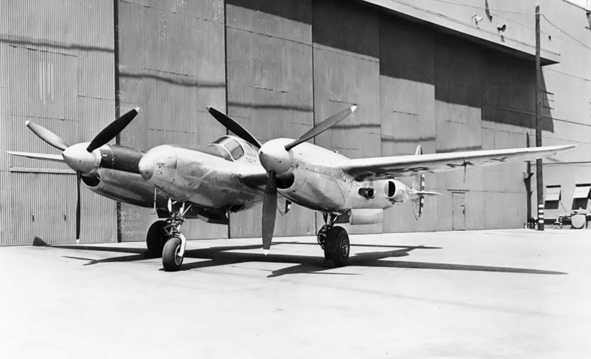
The Lockheed XP-49 was obviously a development of the P-38, with the airframes sharing many common parts. However, the XP-49 as built offered no advantage over the P-38, and the aircraft was used mostly as an XI-1430 test bed.
On 22 April 1942, XI-1430 engines that were not fully developed were delivered to Lockheed in Burbank, California for installation in the XP-49. In May, the engine passed a preliminary test at 1,600 hp (1,193 kW). The XP-49 made its first flight on 11 November 1942, piloted by Joe Towle. That same month, the AAF ordered 100 I-1430 engines but required a type test to be passed before delivery. At the end of November, the XP-49 had more powerful engines installed capable of 1,350 hp (1,006 kW) for takeoff and 1,600 hp (1,193 kW) at 25,000 ft (7,620 m). The engines in the XP-49 proved to be troublesome and required constant maintenance, and the aircraft itself had numerous issues. The I-1430 was also having trouble passing the type test. Around August 1943, the AAF cut its order to 50 engines and later reduced the quantity again to 25. By September 1943, the XP-49 became essentially a testbed for the XI-1430, as the aircraft offered no advantage over the P-38. It was clear that the XP-49 would not go into production.
McDonnell had built a full-scale XP-67 engine nacelle for testing the XI-1430 engine installation. Tests were conducted by McDonnell starting in May 1943. After accumulating almost 27 hours of operation, the rig was sent to the National Advisory Committee for Aeronautics (NACA) at the Langley Memorial Aeronautical Laboratory (now Langley Research Center) in Virginia. The NACA added about 17.5 hours to the engine conducting tests to analyze the installation’s effectiveness for cooling the coolant, oil, and intercooler. The tests indicated that the cooling was insufficient. The nacelle with revised ducts was then shipped to Wright Field in Dayton, Ohio in October 1943. Wright field added another 6.5 hours to the engine, bringing the total to 51 hours. The new ducts proved satisfactory, and McDonnell was allowed to proceeded with XP-67 testing. However, excessive vibrations were noted between the engine and its mounting structure, and a more rigid mount was required to resolve the issue.
On 1 December 1943, the XP-67 had its XI-1430 engines installed and was ready for ground tests. However, both engines caught fire and damaged the aircraft on 8 December. The fire was caused by issues with the exhaust manifolds. By the end of 1943, the AAF had reduced the I-1430 order to just eight engines, signaling that the engine would not enter quantity production. The XP-67 was repaired and made its first flight on 6 January 1944, taking off from Scott Field in Belleville, Illinois. Test pilot Ed E. Elliott had to cut the flight to just six minutes due to both turbosuperchargers overheating, which resulted in small fires. The aircraft was again repaired, but engine and turbosupercharger issues continued to plague the program. The engines were only delivering 1,060 hp (790 kW), well below the expected output of 1,350 hp (1,007 kW).

Underside of an XI-1430-17 installed in the McDonnell XP-67 wing section for tests at the Langley Memorial Aeronautical Laboratory in September 1943. The tests were conducted to evaluate the cooling ducts of the XP-67’s radical blended design. Illustrated is the engine’s intake manifold and two coolant radiators. Note the generator and starter installed on the front accessory drive. The air-cooled jackets surrounding the engine’s exhaust manifolds are also visible. (LMAL image)
In March 1944, the I-1430 type test was partially completed, and the eight engines ordered by the AAF were delivered. At the time, the engine achieved an emergency power rating of 2,000 hp (1,491 kW) with water injection. Continental continued its efforts, and in August 1944, the I-1430 earned a rating of 2,100 hp (1,566 kW) with 150 PN fuel and no water injection.
On 6 September 1944, the exhaust valve rocker of the No. 1 cylinder in the XP-67’s right engine broke while the aircraft was in flight. Exhaust gases unable to escape the cylinder backed up into the induction manifold and caused it to fail, resulting in a fire. Test pilot Elliott was able to land the aircraft, but it was subsequently damaged beyond repair by the fire. This event effectively killed the XP-67, and the project was suspended seven days later on 13 September. All XI-1430 development was halted around this time.
The XP-49 had continued to fly when it could, but engine and airframe issues caused the aircraft to be grounded in December 1944. No longer of any useful service, the XP-49 was subsequently scrapped.
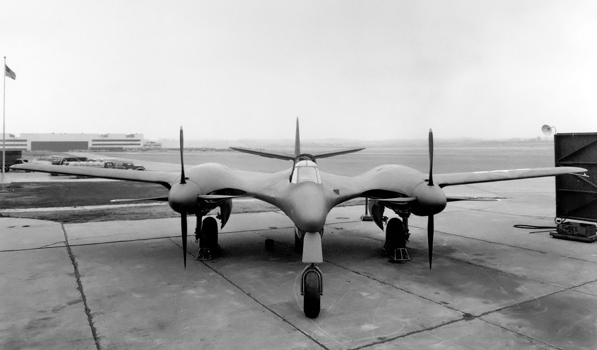
The XP-67 had an impressive appearance with its nacelles and fuselage blended into the wings. However, the XI-1430 engines did not deliver their expected power, and the XP-67’s top speed was 405 mph (652 km/h), well below the expected 448 mph (721 km/h). The XP-67 originally had a guaranteed speed of 472 mph (760 km/h) at 25,000 ft (7,620 m) with a gross weight of 18,600 lb (8,437 kg). Once its weight had increased to 22,500 lb (10,206 kg), the expected speed was reduced to 448 mph (721 km/h).
Continental had investigated designs for XI-1430 engines with a two-speed supercharger, a two-stage and two-speed supercharger, contra-rotating propellers, a spur-gear-only propeller reduction, and turbocompounding with a turbine feeding power back to the crankshaft. Continental was to supply XI-1430 engines with a contra-rotating propeller shaft for the second XP-67. The engines were expected in June 1944, but no further information has been found.
Continental did work with General Electric on a turbocompound XI-1430 in 1943, and it appears detailed design work was undertaken. The XP-67 was used for performance calculations with a turbocompounded XI-1430 engine. The turbocompound engines decreased the time of a climb to 25,000 ft (7,620 m) by approximately 38 percent and increased range by 25 percent. The turbocompound XI-1430’s output was an additional 580 hp (395 kW). The engine with its power recovery turbine weighed an additional 235 lb (107 kg), but the total installation weight was only 30 lb (14 kg) additional because a turbosupercharger and its ducting was not needed. In February 1944, Materiel Command’s Engineering Division encouraged the completion of a turbocompound XI-1430 engine to test against the calculated performance estimates, but it does not appear that a complete engine was ever built.
Although the XI-1430 was lighter and more powerful than comparatively sized engines in production, it required additional development to become reliable. It was obvious that the engine would not see combat in World War II, and there was little point in continuing the program. A total of 23 XI-1430 engines were built, and at least six engines are known to survive. A -11 and a -15, are held by the Smithsonian Air and Space Museum, a -9 is on display at the National Museum of the U.S. Air Force, a running -11 is part of a private collection, and two other unrestored engines are part of another private collection.

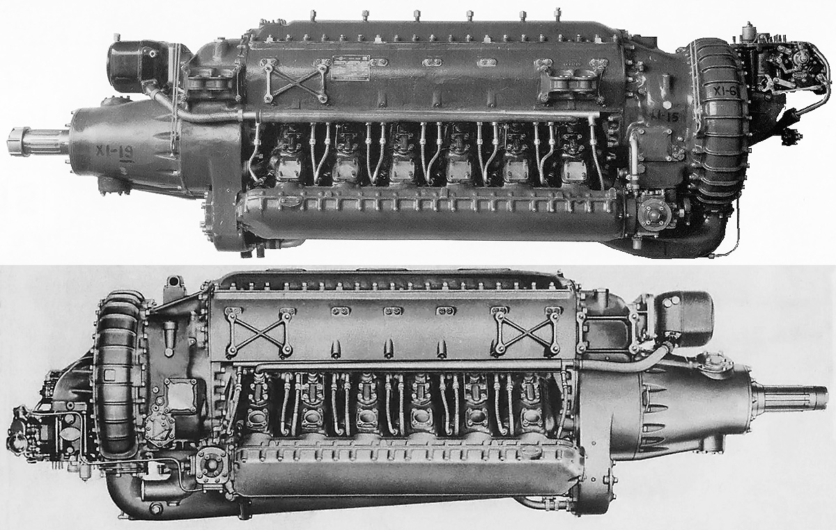
The two XI-1430 engines held by the Smithsonian Air and Space Museum, with the -11 at top and the -15 at bottom. Both examples rotate counterclockwise (left-handed). The engines are currently in storage and not on display. (NASM images)
Sources:
– Development of Aircraft Engines and Aviation Fuels by Robert Schlaifer and S. D. Heron (1950)
– Continental! Its Motors and its People by William Wagner (1983)
– Aircraft Engines of the World 1946 by Paul H. Wilkinson (1946)
– Service Instructions for Aircraft Engines Army Models I-1430-9 and -11 By (20 May 1943)
– Performance of the McDonnell XP-67 Airplane with XI-1430 Compound Engines and with Present XI-1430 Engines Using Continental Turbo Chargers by J. H. Gilmore, E. P. Kiefer, and H. D. Delameter (25 February 1944)
– U.S. Experimental & Prototype Aircraft Projects: Fighters 1939-1945 by Bill Norton (2008)
– American Secret Pusher Fighters of World War II by Gerald H. Balzer (2008)
– Final Report on the XP-67 Airplane by John F. Aldridge, Jr. (31 January 1946)
– Tornado: Wright Aero’s Last Liquid-Cooled Piston Engine by Kimble D. McCutcheon (2001)
– “Fabricated Crankcase Structure” U.S. patent 2,340,885 by James W. Kinnucan (filed 7 December 1940)
– “Cylinder Head” U.S. patent 2,395,712 by Carl F. Bachle (filed 12 January 1942)
– Accessory Mechanism and Drive for Aircraft Engines” U.S. patent 2,410,167 by James W. Kinnucan (filed 20 March 1942)
– http://www.enginehistory.org/Collections/IV-1430/iv-1430.shtml
– https://airandspace.si.edu/collection-objects/continental-hyper-i-1430-11-inverted-v-12-engine
– https://airandspace.si.edu/collection-objects/continental-hyper-xi-1430-15-inverted-v-12-engine