Monthly Archives: March 2021

Wright-H-2120-No-1-front-left

Wright H-2120 Hexagonal Engine

By William Pearce

In April 1926, the Curtiss Aeroplane and Motor Company (Curtiss) initiated the design of a 600 hp (447 kW) air-cooled aircraft engine. The engine was of a “hexagonal” design, with six banks of two cylinders, and had a relatively small diameter. Known was the H-1640 Chieftain, the two-row engine experienced some cooling issues and was abandoned shortly after the merger of Curtiss with Wright Aeronautical (Wright) in July 1929.

Wright-H-2120-No-1-front-left

The liquid-cooled Wright H-2120 was developed from the air-cooled Curtiss H-1640 Chieftain. The engine was designed when experiments with two-row radials had just begun and concerns existed about air-cooling being sufficient for the rear cylinders.

In 1930, the United States Navy (Navy) initiated a special “high-speed development program” to challenge the success achieved by foreign high-speed aircraft, especially those demonstrated in the 1929 Schneider Trophy contest. Wright resurrected the hexagon engine design to further exploit its relatively small diameter. Using the H-1640 as a foundation, a liquid-cooled engine with an increased bore and stroke was designed by Wright. The new six-bank engine was to ultimately have four cylinders per bank, giving the 24-cylinder engine a displacement of 4,240 cu in (69.5 L) and an output of over 2,000 hp (1,491 kW). However, development was initiated with just two cylinders in each bank, and the 12-cylinder engine was known as the H-2120.

In June 1931, the Navy issued Contract No. 22625 to Wright for the development of two 1,000 hp (746 kW) H-2120 engines. From these developmental engines, a service type was to be derived. The Navy, always with an interest in air-cooled engines, stipulated that an air-cooled version was to be developed as either a companion to or a replacement of the liquid-cooled version. The Navy felt the air-cooled H-2120 could serve as competition and a backup to the 870 hp (649 kW), air-cooled, 14-cylinder Pratt & Whitney R-2270 radial, which was under development.

In a sense, the Wright H-2120 was three V-4 engines on a common crankcase, which created its hexagonal shape when viewed from the front. The two-row engine had an aluminum, three-piece crankcase that was split vertically at the centerline of the cylinders. The crankcase sections were secured together with bolts positioned between the cylinder banks. The single-piece, two-throw, crankshaft was supported by three main bearings. An odd connecting rod arrangement consisted of one blade rod, four articulated rods, and one fork rod. However, the blade and fork rod moved as a unit, as the pins that held the articulated rods passed through both the blade rod and the fork rod. The connecting rod arrangement was referred to as having dual master rods, with both the blade rod and fork rod technically considered master rods.

Wright-H-2120-No-1-front

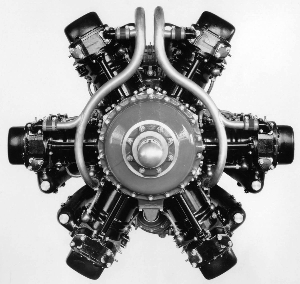
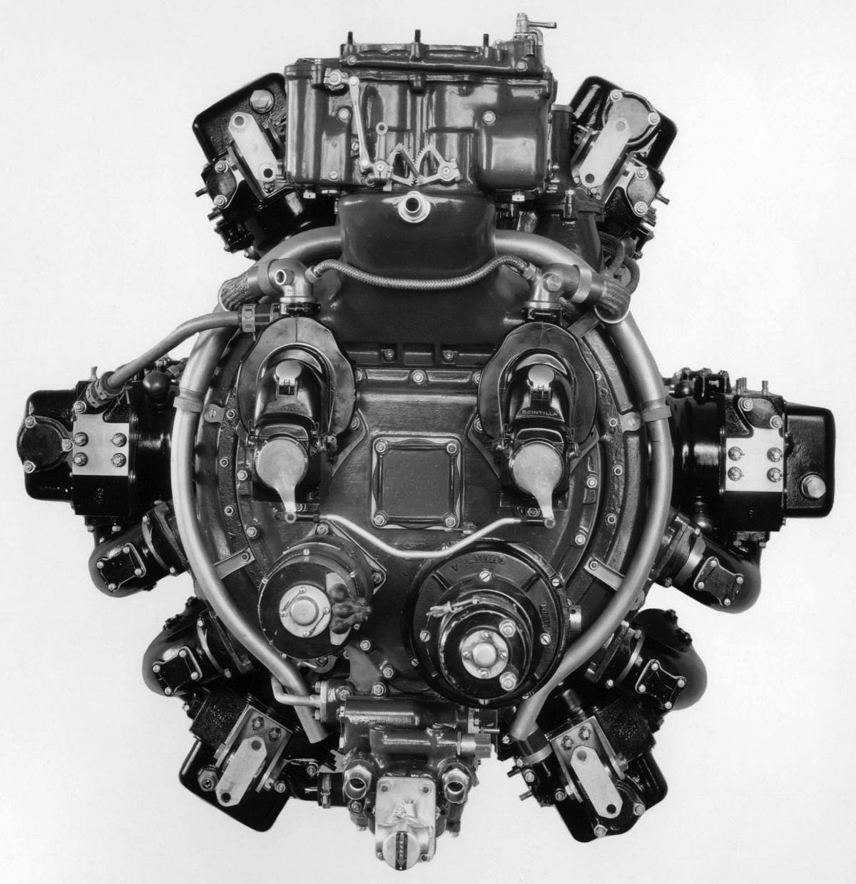
With six cylinder banks, the front view of the H-2120 illustrates its hexagonal shape. Note the coolant manifolds at the front of the engine.

The cylinder banks were spaced at 60-degree intervals around the crankcase, with the left and right banks perpendicular to the engine. The individual cylinders had a steel barrel surrounded by a steel water jacket. Each cylinder pair that formed a bank had a common cylinder head. Each cylinder had two intake valves and two exhaust valves, all actuated by dual overhead camshafts. The camshafts for each cylinder bank were geared to a vertical shaft driven from the front of the engine. The cylinders had a compression ratio of 6.5 to 1.

Mounted to the front of the engine was a planetary gear reduction that turned the propeller shaft at .6875 times crankshaft speed. At the rear of the engine was a single-speed supercharger that turned at 5.45 times crankshaft speed. Air was drawn through a downdraft carburetor, mixed with fuel, and compressed by the supercharger’s 11 in (279 mm) impeller. The air and fuel mixture was distributed to each of the six cylinder banks by a separate manifold. Each manifold had four short runners to deliver the charge to each cylinder’s two intake ports. The cylinder banks were arranged so that their intake and exhaust sides were mirrored with the adjacent cylinder banks. Each cylinder’s two spark plugs were fired by magnetos positioned at the rear of the engine. Coolant for the top four cylinder banks was circulated up from the base of each cylinder water jacket and through the cylinder head. Coolant for the lower two cylinder banks was the reverse—it flowed through the inverted head and up to the base of the water jacket.

The Wright H-2120 had a 6.125 in (156 mm) bore, a 6.0 in (152 mm) stroke, and a total displacement of 2,121 cu in (34.76 L). The engine had a sea level rating of 1,000 hp (746 kW) at 2,400 rpm with 2.2 psi (.16 bar) of boost, and it had a takeoff rating of 1,100 hp (820 kW). The H-2120 was 49 in (1.24 m) in diameter and was 57 in (1.45 m) long. The engine weighed 1,440 lb (653 kg).

Wright-H-2120-No-1-left

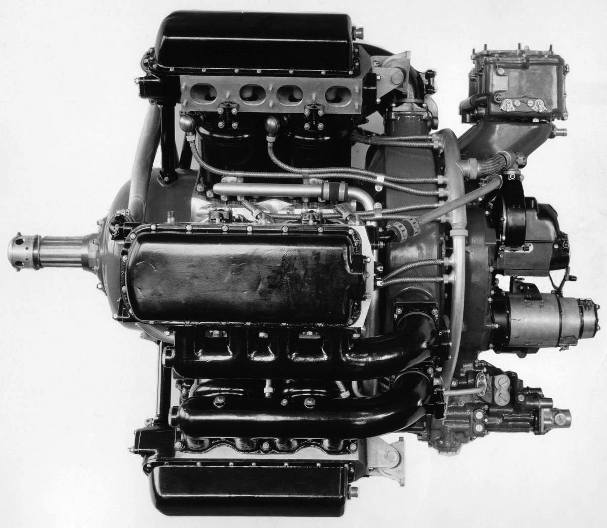
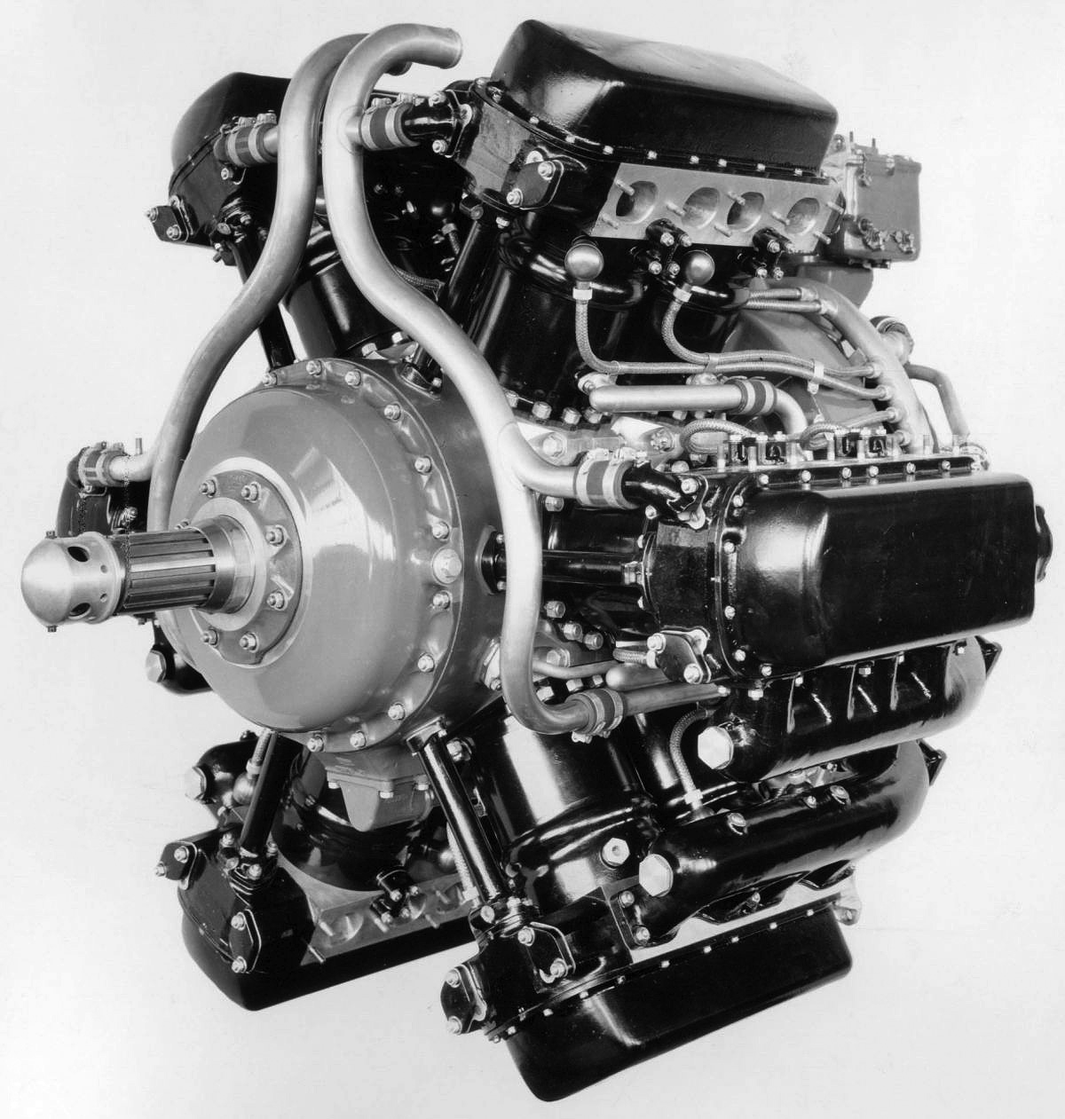
Side view of the first H-2120 illustrates the relatively short length of the engine. Note the supercharger housing and the intake manifolds.

The first H-2120 engine carried the Wright Manufacture’s No. 11691 and the Navy Bureau of Aeronautics No. (BuNo) 0120. The BuNo is often incorrectly recorded as 0210 or 0119 in Wright and Navy documentation. The H-2120 engine encountered issues that delayed its development. The issues were mainly focused on the connecting rod arrangement. Several different connecting rod arrangements were tested and discarded before the dual master rod type was adopted. The engine was first run in late 1933 or early 1934. It failed a 50-hour endurance test conducted by Wright in January 1935, but the cause of the failure has not been found. The test involved 10 cycles of running the engine for 30 min at 1,000 hp (746 kW) and 4.5 hours at 900 hp (671 kW). The endurance test was rerun, and the H-2120 passed on 10 May 1935.

The Army Air Corps (AAC) was seeking an engine capable of 1,250 hp (932 kW) for takeoff and had been following the development of the H-2120. Starting around January 1935, the Navy and Wright began to share information on the engine’s development with the AAC. In August 1935, progress on the engine had again slowed, and the AAC asked the Navy if it could assist with H-2120 testing and development. The Navy had planned to use the first engine for bench testing and the second engine for at least 25 hours of flight tests. By early September, the first engine was in the middle of a 50-hour Navy type test, with other tests yet to be conducted. The Navy had lost interest in the liquid-cooled engine and was planning to convert the second engine to air-cooling after the 25 hours of flight trials. The conversion was expected to involve just new cylinders and valve gear. If all went well, two additional air-cooled engines would be ordered that incorporated whatever changes were deemed desirable from the previous tests. The second engine was Manufacture’s No. 11692 / BuNo 0121, and it was undergoing its initial test runs after assembly at Wright.

In response to the AAC’s request, the Navy proposed that it continue tests with the first engine, and the second engine would be delivered to the AAC for flight tests. If the AAC wanted to test the engine beyond the 25 hours, they were free to do so. If the engine showed promise, the Navy would order a small number of air-cooled versions. The AAC agreed to these terms, provided they could do some preliminary engine tests before the H-2120 was installed in an aircraft.

Wright-H-2120-No-1-rear

Rear view of the engine shows the downdraft carburetor, two magnetos, generator, and starter. Water pumps were located at the bottom of the engine.

By the end of September 1935, testing had included 200 hours of single cylinder tests, and the first H-2120 had completed 56 hours at 1,000 hp (746 kW), 44 hours at 900 hp (671 kW), and 140 hours of calibration and miscellaneous tests. A 50-hour Wright endurance test and a 50-hour Navy type test had been completed. During the Navy test, which was completed on 15 September 1935, four leaks had developed in the water jackets, one camshaft broke, and one valve guide had cracked. The Navy wanted to complete a 150-hour test. The two 50-hour tests counted for 100 hours, and the 140 hours of calibration counted for 25 hours. Wright offered to complete at their own expense the final 25 hours of the 150-hour test. This included 15 hours alternating between 1,100 hp (820 kW) takeoff power and idle, and 10 hours at 1,000 hp (746 kW) and 110% maximum engine speed (2,640 rpm).

On 7 November 1935, the AAC received the second H-2120 engine. The AAC had selected a Bellanca C-27A single-engine transport to serve as the H-2120 test bed. The engine’s installation would add 860 lb (390 kg) to the aircraft. After further evaluation, it was determined that the center of gravity would be out of limits, and the C-27A was deemed unsuitable for the engine tests. A Fokker C-14A was substituted, and serial number 34-100 was assigned for the conversion on 15 November.

Testing of the first engine at Wright had run into issues. After 4.5 hours at 2,640 rpm, an intake valve failed, resulting in a severe backfire. During inspection, the blower housing was found to be cracked, the crankcase had been punctured, and several connecting rods were damaged. Some of the damaged connecting rods were a result of improper assembly. The engine was repaired but damaged again on 20 November, when anther intake valve failed after 3.25 hours at 2,640 rpm. Before the failure, the H-2120 was producing 1,168 hp (871 kW) with a coolant and oil outlet temperature of around 255 ℉ (124 ℃). The engine was repaired again and completed its 10 hours at 2,640 rpm on 23 December 1935. The first H-2120 was retained by Wright for further tests.

By the end of December 1935, the AAC had run in the second engine for five hours and up to 2,300 rpm. The fuel pump diaphragm failed four times, necessitating replacement of the pump. After some vibration issues were overcome, calibration tests were started in mid-January 1936. The AAC concluded its tests in April, stating that the second H-2120 ran smoothly. The engine produced 1,000 hp (746 kW) at 2,400 rpm with 1.8 psi (.12 bar) of boost. It also developed 1,139 hp (849 kW) at 2,550 rpm with 3.2 psi (.22 bar) of boost. Installation of the H-2120 in the C-14A was forecasted to add 800 lb (363 kg), and the AAC felt that more information could be gained by continued ground testing rather than flight tests in the C-14A.

Wright-H-2120-No-1-NASM-front-left

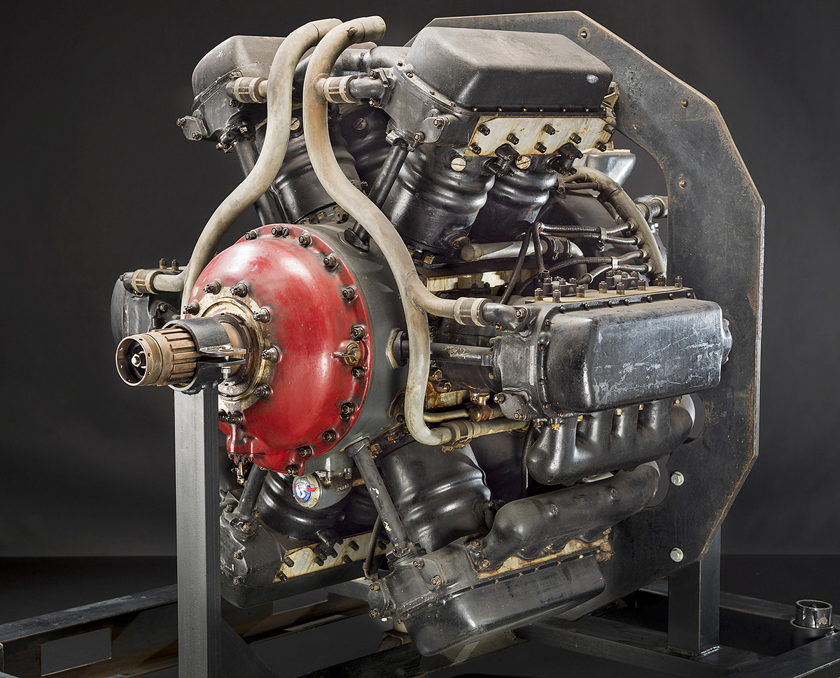
The first H-2120, Manufacture’s No. 11691 / BuNo 0120 appears to be complete. It is not known if it was repaired after its rear connecting rod failure. (NASM image)

Meanwhile, testing of the first H-2120 had continued at Wright. On 20 February 1936, the blade connecting rod on the rear crankpin failed during calibration for a 20-hour test at takeoff power (1,100 hp / 820 kW). The failure was the result of fatigue, and the broken rod caused significant damage to all nearby components.

In May 1936, Wright informed the AAC and Navy of a secret air-cooled engine that is had been developing at its own expense. This engine was expected to have an initial sea level rating of 1,200 hp (894 kW) and a takeoff rating of 1,400 hp (1,044 kW). Wright offered the services an experimental version of the engine for $38,750, with delivery expected in early 1937. Wright did not want any details of this engine leaked to its competitors and asked that the AAC and Navy refer to it as the “Aircooled 2120,” even though that was not the engine’s displacement. Wright felt that this new engine, which was the 14-cylinder R-2600 radial, possessed more potential than the H-2120. Wright wanted to drop further H-2120 development to focus on the R-2600. Both the AAC and the Navy agreed, encouraged Wright to continue R-2600 development, and stated their intention of purchasing experimental examples once money for the 1937 budget was available. The Navy had already lost interest in the H-2120, and the AAC stopped further testing in July.

During the fall of 1935, the Boeing Airplane Company, the Curtiss Aeroplane & Motor Company, and the Glenn L. Martin Company all requested data on the H-2120 so that they could potentially incorporate the engine into designs they were working on. Since the H-2120 was a joint project at the time, the service that received the request would check with the other service to see if there were any objections to sharing information. The only company denied data was North American Aviation, which requested information in January 1936. Both the AAC and Navy said they had no projects with the company that required an engine like the H-2120. Despite the interest, no applications for the H-2120 have been found.

Both H-2120 engines survive and are held in storage by the Smithsonian National Air and Space Museum. The first engine, Manufacture’s No. 11691 / BuNo 0120, is complete. It is not known if it was fully repaired after the failure of the rear connecting rod, or just reassembled. The second H-2120, Manufacture’s No. 11692 / BuNo 0121, was sectioned to expose its inner workings. The H-2120 represented the last of the hexagonal engines from the United States. Other hexagonal engines include the Curtiss H-1640, the SNCM 137, the Junkers Jumo 222, and the Dobrynin series of aircraft engines.

Wright-H-2120-No-2-NASM-sectional

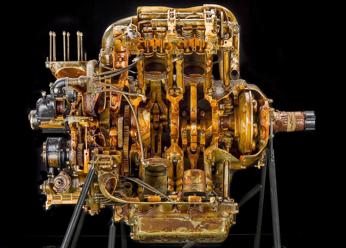
The second H-2120, Manufacture’s No. 11692 / BuNo 0121, neatly sectioned and displaying its internals. Note the four valves per cylinder and odd connecting rods. (NASM image)

Sources:
– Numerous documents held by the U.S. National Archives and Records Administration at College Park, Maryland under Record Group 342 – Air Force Engineering Division RD 1676 and 3285 (scanned by Kim McCutcheon of the Aircraft Engine Historical Society)
Development of Aircraft Engines and Aviation Fuels by Robert Schlaifer and S. D. Heron (1950)
https://airandspace.si.edu/collection-objects/wright-ch-2120-radial-12-engine/nasm_A19731548000
https://airandspace.si.edu/collection-objects/wright-xr-2120-radial-12-engine-cutaway/nasm_A19710896000

Rail-Zeppelin-rear-four-blade-21-10-1930

Rail Zeppelin Propeller-Driven Railcar (Schienenzeppelin)

By William Pearce

During World War I, German engineer Otto Steinitz had the idea of testing aircraft engines and propellers on railcars. Carl Geissen designed the engine mount, and testing was carried out on a special track at the German Aviation Research Institute (Deutschen Versuchsanstalt für Luftfahrt, DVL) in Berlin. The test car reached speeds of up to 97 mph (140 km/h). After the war, the propeller-driven railcar concept led Steinitz to design a special two-axle car with a mount for an aircraft engine at each end. An enclosed area between the engines housed the crew, passengers, and equipment. Known as the Dringos-Wagen, the machine made a 25-mile (40-km) test run from Grunewald to Beelitz on 11 May 1919. Loaded with approximately 40 people (possibly 35 passengers and five crew), the Dringos-Wagen experienced slow acceleration and a limited top speed of about 37 mph (60 km/h). Interest in Steinitz’s Dringos-Wagen declined after the test, but Geissen continued to design propeller-driven railcars for passenger service into the early 1920s.

Dringos-Wagen

The Dringos-Wagen testing the concept of a propeller-driven railcar in 1919. Note the radiators installed on the deck

Also in the early 1920s, fellow German engineers Kurt Wiesinger and Franz Friedrich Kruckenberg had similar ideas of using propellers to improve and quicken rail traffic. Wiesinger envisioned propelling railcars along the tracks with propellers, while Kruckenberg was considering a streamlined, propeller-driven gondola suspended from a single overhead track as a Zeppelin-on-rails. Kruckenberg’s design was similar to George Bennie’s Railplane of the same period. The pair met in 1923 but soon had a falling out and went their separate ways.

Kruckenberg had studied shipbuilding at the Technical University in Danzig (now Gdańsk University of Technology). One of his professors, Johann Schütte, had partnered with industrialist Karl Lanz to form Luftschiffbau Schütte-Lanz (Airship Construction Schütte-Lanz) in April 1909. After his graduation in August 1909, Kruckenberg joined the firm as a developmental engineer. Kruckenberg was involved with both airship and aircraft constructions while working at Schütte-Lanz, and he was the firm’s chief designer and director of aircraft production during World War I.

After World War I, Kruckenberg left Schütte-Lanz and began to focus on ways to improve rail travel, which is when he met Wiesinger. In July 1924, Kruckenberg partnered with Curt Stedefeld, an associate from university who had also worked for Schütte-Lanz and had founded the Company for Traffic Engineering (Gesellschaft für Verkehrstechnik, GVT) to promote the overhead rail system. Despite a forecasted top speed of 224 mph (360 km/h), the German Ministry of Transportation (Reichsverkehrsministerium) and the German State Railroad Company (Deutschen Reichsbahn-Gesellschaft, DRG) were not willing to offer any financial support. The main objection was the cost of the overhead rail system, which required the support and construction of a completely new infrastructure.

DVL-Propellerwagen

The DVL’s Propellerwagen was strictly a test machine and not intended to transport passengers. However, the Propellerwagen provided important information on suspension and handling that was applied to the Rail Zeppelin.

In April 1928, Kruckenberg and Stedefeld founded the Railplane Company (Flugbahn-Gesellschaft, FG) in Heidelberg. The purpose of the new company was to build a propeller-driven railcar for experimentation on existing rail lines to validate the concepts of the overhead rail system. Once FG had demonstrated reliable performance on existing rails, it was hoped that the DRG would be willing to support the overhead rail system.

Around the same time, the DVL was interested in constructing a Propellerwagen to revive the testing of engines and propellers on railcars. Both FG and DVL had petitioned the DRG for the use of a straight, 5-mile (8-km) long, unused track between Langenhagen and Celle. The DRG proposed that the FG and the DVL work together to build a test rig that could be used to test engines and propellers and validate the concepts of propeller-driven railcars.

The DVL Propellerwagen test railcar was completely enclosed with an engine and propeller at each end. The narrow machine was tall with flat sides and had two axles. The rear engine drove its propeller directly via a long shaft, while the front engine drove an elevated propeller shaft via a wide belt. Both engines were six-cylinder, inline BMW IVs that produced 250 hp (186 kW) at 1,400 rpm. The test car weighed around 30,865 lb (14,000 kg) and had a top speed of 109 mph (175 km/h). After operating under its own power for the first time in April 1929, the test railcar eventually made 82 runs that totaled approximately 620 miles (1,000 km). While the DVL test machine did not help advance GVT/BG’s study of aerodynamics, it did provide important information about suspension, handling, and the operation of a propeller-driven railcar.

Rail-Zeppelin-no-body-30-08-1930

The bodyless Rail Zeppelin on 30 August 1930 illustrating the machine’s intricate frame. Note the numerous lightening holes in the truss frame. The engine-driven centrifugal fan drew in air via the circular opening (one on each side). The air was then forced through the large, square radiator in the lower rear of the railcar.

With information from the RVL tests in hand, Kruckenberg and his team compared diesel-electric drives against propeller drives for their railcar. They found that the diesel-electric would cost about 19 times more than the propeller drive and would weigh around 19,842 lb (9,000 kg), compared to 772 lb (350 kg) for the propeller and engine. In June 1929, the design of a streamlined, propeller-driven Railplane Express Car (Flugbahn-Schnellwagen) was laid out and designated Propeller Railcar A (Propellertriebwagen A). This machine was undoubtedly inspired to some degree by the earlier designs of Geissen and Wiesinger. Detailed design work was done in October 1929, and wind tunnel models were tested the following month. Due to its design, construction, and appearance, the streamlined, high-speed railcar became commonly known as the Rail Zeppelin (Schienenzeppelin).

The Rail Zeppelin consisted of a steel chassis with an aluminum truss frame. The engine supports and some other components were also made of steel. The aluminum frame was perforated with extensive lightening holes. The machine was supported on two axles and had a wheelbase of 64 ft 4 in (19.60 m). The axles used rubber ball dampeners for their suspension. Each of its four wheels were 39 in (1.0 m) in diameter. The inner flange of the wheels was made taller than normal to help prevent any possible derailments caused by the machine’s anticipated high speeds. Air-powered friction brakes were used to slow the Rail Zeppelin. An electric drive motor powered the front axle for moving the machine in a limited manner up to 12.4 miles (20 km) and at relatively slow speeds.

Rail-Zeppelin-front-left

The completed Rail Zeppelin displaying its streamlined form for press photographers. Note the two exhaust stacks at the rear of the machine and its long wheelbase.

Above the rear axle was a single BMW VI liquid-cooled V-12 engine. The BMW VI had a 6.30 in (160 mm) bore and a 7.48 in (190 mm) stroke. The engine displaced 2,797 cu in (45.84 L) and produced 500 hp (373 kW) at 1,410 rpm and 600 hp (447 kW) at 1,540 rpm. The engine’s exhaust was expelled through two vertical stacks. The drive end of the engine pointed toward the rear of the Rail Zeppelin and was elevated seven degrees. A shaft, which was also angled at seven degrees, extended approximately 7 ft 7 in (2.3 m) back to the rear of the machine and turned a four-blade, fixed-pitch Heine propeller made from ash wood. The seven-degree angle on the propeller applied downward force on the Rail Zeppelin and directed the propwash up and away from people on rail platforms. The propeller was 9 ft 2 in (2.80 m) in diameter and was comprised of two stacked two-blade units.

Also attached to the drive end of the engine was a centrifugal fan that circulated cooling air through the engine compartment. Air was drawn in via vents on each side of the Rail Zeppelin and entered a duct at the center of the machine. The air then passed through radiators and was expelled out from the bottom of the Rail Zeppelin. The engine also powered the compressor for the air brakes and two generators for the electrical system. Storage batteries were located in the train’s nose.

The Rail Zeppelin was covered by a streamlined, aerodynamic body. The front, lower sides, and rear of the machine were covered by aluminum sheeting. Windows extended along the sides of the passenger compartment. Due to the expected speed of the Rail Zeppelin, none of the windows opened, and ventilation was provided by forced air. The top of the railcar was covered with fire-proof canvas.

Rail-Zeppelin-rear-four-blade-21-10-1930

Rear view of the Rail Zeppelin with its four-blade propeller. The grate on the side was the cooling air intake. The circular housing under the propeller was for lights.

Two drivers sat side-by-side at the front of the train in a raised cockpit, which also had seats for two observers. Passenger compartment access doors were positioned at the front, middle, and rear on each side of the Rail Zeppelin. The 8 ft 2 in (2.5 m) wide and 52 ft 6 in (16 m) long passenger cabin was insulated and had wood paneling. As designed, the passenger compartment consisted of six sections, with each section accommodating four passengers, and a central aisle extended through each section. In addition to the 24-seat configuration, an alternative configuration with bench seating could accommodate 44 passengers. A lavatory was provided at the rear of the cabin. As built, only the forward three compartments were completed, and the rear three compartments held test equipment. The Rail Zeppelin was 84 ft 10 in (25.85 m) long, 8 ft 9 in (2.66 m) wide, and 9 ft 2 in (2.80 m) tall. The railcar weighed 40,962 lb (18,580 kg).

Construction of the Rail Zeppelin started in early 1930 at the DRG repair works in Leinhausen, near Hannover. Without its body, the railcar was mostly complete in August 1930 and moved under its own power with the electric motor. The body was added, and the Rail Zeppelin was completed in September. The first test with propeller power occurred on 25 September 1930. During the first high-speed test, the Rail Zeppelin reached 62 mph (100 km/h) after 66 seconds and 3,232 ft (985 m) of forward travel. The machine hit 93 mph (150 km/h) after two minutes, and the throttle was pulled back just past three minutes at 113 mph (182 km/h).

Rail-Zeppelin-two-blade-station

The Rail Zeppelin with its two-blade propeller sits at Spandau (Berlin) station after its run on 21 June 1931. The two-blade propeller improved the machine’s top speed but slowed acceleration.

The initial testing was done in secret and revealed that braking was an issue. Due to the Rail Zeppelin’s streamlining and relatively light weight, light breaking took a long distance, and heavy breaking had a tendency to lock the rear axle. In one instance, the brakes locked the rear axle at 112 mph (180 km/h), and it took 1.2 miles (2 km) for the railcar to come to a stop. A flat spot on the rear wheels about .14 in (3.5 mm) deep was discovered during a quick inspection, but the Rail Zeppelin was still operated up to 87 mph (140 km/h) on its return trip.

On 18 October 1930, the Rail Zeppelin was debuted to the press. Tests continued, some of which involved DRG officials. To test the concept of using a propeller with adjustable-pitch blades, a propeller with reversed pitch was installed, and the Rail Zeppelin was run backward at 37 mph (60 km/h). With the normal forward-thrust propeller reinstalled, propeller braking tests were conducted. The electric motor was used to reverse the train at 28 mph (45 km/h). Then the propeller was engaged, and it alone halted the Rail Zeppelin in 20 seconds. These tests indicated that a fully reversible pitch propeller would greatly enhance the Rail Zeppelin’s braking and improve its safety.

Rail-Zeppelin-top

This upper view of the Rail Zeppelin in Berlin illustrates the machine’s canvas covering over its upper body. Note the windshield wipers and the two-blade propeller.

Testing on the isolated track continued until May 1931, when the Rail Zeppelin was operated on the main line. However, no German insurance company would cover the propeller-driven train, and arrangements had to be made with Lloyd’s of London for coverage. The main line test was a 12.2-mile (19.7-km) stretch between Plockhorst and Lehrte. The Rail Zeppelin drew quite a crowd wherever it operated, necessitating a police presence to control the spectators. On 10 May, the machine covered the distance in 10 minutes and reached a top speed of 127 mph (205 km/h).

Testing over a longer distance was needed, so the 160-mile (257-km) route between Hamburg and Berlin was selected. The four-blade propeller was switched in favor of a two-blade unit that would provide a higher top speed at the cost of acceleration. The two-blade propeller was of the same construction as the previous propeller—fixed pitch, wood, and 9 ft 2 in (2.80 m) in diameter.

On 21 June 1931, the Rail Zeppelin left the Hamburg-Bergedorf station at 3:27 AM with a number of observers and crew on board. As the train traveled, its speed continued to increase. However, the track speed limit around many of the curves was 62 mph (100 km/h), which caused the Rail Zeppelin to slow often and accelerate on the straight stretches. Over the 7.5 miles (12-km) separating Karstädt and Dergenthin, the Rail Zeppelin averaged 143.0 mph (230.2 km/h)—a new speed record for passenger rail travel that would stand until 1954. The train arrived in Berlin at 5:05 AM with an average speed of 97.7 mph (157.3 km/h). Along the way, the Rail Zeppelin burned only 48.6 US gal (40.5 Imp gal / 184 L) of fuel, which averaged to 3.3 miles per US gal (1.4 km/L).

Rail-Zeppelin-four-blade-station

With its propeller spinning, the Rail Zeppelin awaits departure at a station. Although the propeller did not really extend beyond the railcar’s body, this view illustrates the rather disconcerting proposition of passengers coming into close proximity of the large propeller. Note the open middle access door.

After its record run, the Rail Zeppelin was put on display at the Rennbahn-Stadion (now Olympiastadion) railway station in Berlin until 25 June 1930. After the display, the train embarked on a short tour of Germany. The four-blade propeller was reinstalled for the tour, and the speed was kept down to conform with normal scheduled traffic on the line. Once again, the Rail Zeppelin drew large crowds wherever it went. The machine returned to Hannover on 28 June.

A new electromagnetic braking system was installed on the Rail Zeppelin and was tested in March 1932. The system was able to stop the train from 103 mph (165 km/h) in 2,067 ft (630 m). While this was a definite improvement, the distance was still longer than desired. Although the Rail Zeppelin had achieved some level of success, the practicality of such a machine was in question. The train’s long wheelbase caused issues on tight curves, and its ineffective brakes necessitated long stopping distances. The propeller-driven design did not allow coupling multiple units together, and the machine was unable to easily maneuver forward and back for short distances. The large propeller always presented a level of danger to anyone in close proximity to the Rail Zeppelin, and that included passengers waiting on rail platforms.

Rail-Zeppelin-Diesel-hydraulic

Image of the modified Rail Zeppelin with propeller removed and the engine installed in the nose. The nose and cockpit were revised for the installation of the engine and the hydraulic drive. Barely visible is the dual-axle front bogie.

Kruckenberg and his team took another look at the future of rail travel, and the propeller-driven railcar concept was discarded in favor of a diesel-hydraulic drive that was much lighter than diesel-electric. In May 1932, modifications were started on the Rail Zeppelin to convert the machine to the new power system. The BMW engine and propeller were removed from the rear, and the engine was temporarily installed in the nose of the train until the intended Maybach GO 5 was available. The GO 5 was a 2,588 cu in (42.4 L) diesel V-12 that produced 410 hp (305 kW) at 1,400 rpm. The engine’s exhaust was collected in a central duct that split the center of the cockpit’s windscreen. Via a Föttinger fluid coupling, the engine drove a double-axle bogie positioned under the cockpit. The bogie had a wheelbase of 6 ft 7 in (2.0 m). To accommodate the changes, the train’s nose was elongated, and its cockpit was raised. Its length was increased to 95 ft 2 in (29.0 m) and its weight increased to 62,832 lb (28,500 kg).

The revised Rail Zeppelin was completed in November 1932. The train was tested in early 1933 and reached 87 mph (140 km/h) in under two minutes after traveling 1.5 miles (2,426 m). It was also run at least to 99 mph (160 km/h). However, the DRG had become interested in other trains, namely those powered by diesel-electric engines. The Rail Zeppelin continued to be tested through 1934 and accumulated over 1,491 miles (2,400 km) with its new drive system. The GO 5 engine was finally installed in 1934, and the machine was sold to the DRG. It does not appear that much testing was done with the GO 5 engine. While Kruckenberg and his team continued to design more conventional locomotives throughout the 1930s, the Rail Zeppelin was placed into storage. In 1939, the Rail Zeppelin was scrapped so that its metal could be used to rebuild the German armed forces.

The Rail Zeppelin and its diesel-hydraulic drive served as the basis for the Kruckenberg-designed SVT 137 155, which could accommodate 100 passengers. A single example of the SVT 137 155 was completed in 1938, and the three-section express train set a conventional passenger train speed record on 23 June 1939 at 134 mph (215 km/h). The SVT 137 155 never entered regular service, and it was scrapped in 1967.

SVT-137-155

The SVT 137 155 built upon the Rail Zeppelin’s diesel-hydraulic experiments. Note the exhaust stack splitting the windscreen.

Sources:
Der Schienenzeppelin by Alfred Gottwaldt (2006)
BMW Aero Engines by Fred Jakobs, Robert Kroschel, and Christian Pierer (2009)
http://greyfalcon.us/FRANZ%20KRUCKENBERG%20SCHIENENZEPPELIN.htm
https://www.julianvonheyl.de/ingenieure/der_schienenzeppelin_von_franz_kruckenberg.shtml
https://interestingengineering.com/this-german-engineer-created-a-hybrid-of-a-train-and-a-zeppelin