By William Pearce
Francois Guidobaldi was born in 1888 and lived in Antibes, France, near Nice and the Italian boarder. In the early 1900s, Guidobaldi became a cycling champion and started to focus on mechanics and engineering. He filed around 28 patents over his lifetime, with a carburetor for automobiles being one of the first, awarded in 1912. In the late 1920s and early 1930s, Guidobaldi was a team mechanic for Benoît Falchetto, who drove Bugatti racers. During that same period, Guidobaldi either founded or worked for the Société anonyme, moteurs à explosion pour aviation, marine et automobiles (MEAMA / the Combustion Engines for Aviation, Marine and Automobiles Corporation), at which he designed and built an air-cooled, two-row, 10-cylinder aircraft engine.
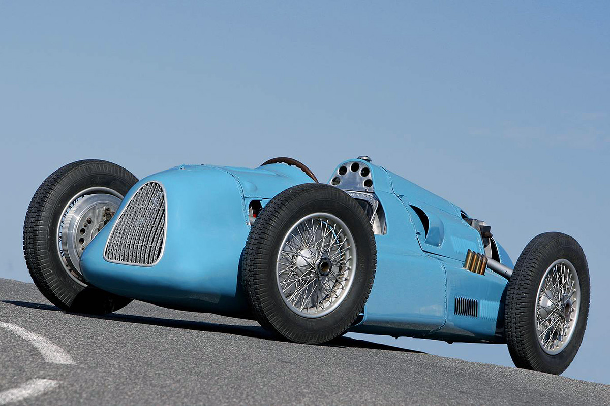
Francois Guidobaldi started work on his race car in 1939, and it took two decades to finish. Looking similar to a late 1930s Auto Union Grand Prix racer, the car’s body hides its unusual suspension system that enabled the chassis to lean into turns and its custom two-stroke, air-cooled, eight-cylinder radial engine. (Cyril de Plater image)
After lengthy consideration and planning in the mid-1930s, Guidobaldi began work on a race car. Guidobaldi’s car would incorporate a number of his ideas on how to improve handling—namely, the body and wheels would tilt in toward the curve when the vehicle was in a turn. This lean would help minimize lateral g-forces and improve the vehicle’s stability. Work on Guidobaldi’s engine design and the car’s chassis development started around 1939. The car’s basic mid-engine layout was similar to that of the Auto Union Grand Prix racers that were very successful in the late 1930s. However, the outbreak of World War II and material shortages after the war caused Guidobaldi to make slow progress on his car, which at times was called the “Guidomobile.”
They chassis of Guidobaldi’s car consisted of two large tubular steel side rails connected by various cross members. Triangular structures at the front and rear of the chassis attached it to the vehicle’s independent suspension. The suspension consisted of a series of rubber dampers sandwiched between steel plates. The chassis mounting point near the top of the triangular suspension structure enabled the chassis to hang and swing like a pendulum from the mount. While in a turn, centrifugal force would swing the chassis and prevent the buildup of lateral g-forces. At the same time, the suspension was engineered so that it would articulate with the body and the steering so that the tires leaned into the turn. The net result of the design was that the car took turns somewhat like a motorcycle. Strong springs connecting the upper suspension links to the chassis centered the chassis when the vehicle was traveling in a straight line and helped moderate the centrifugal effect when in a curve.
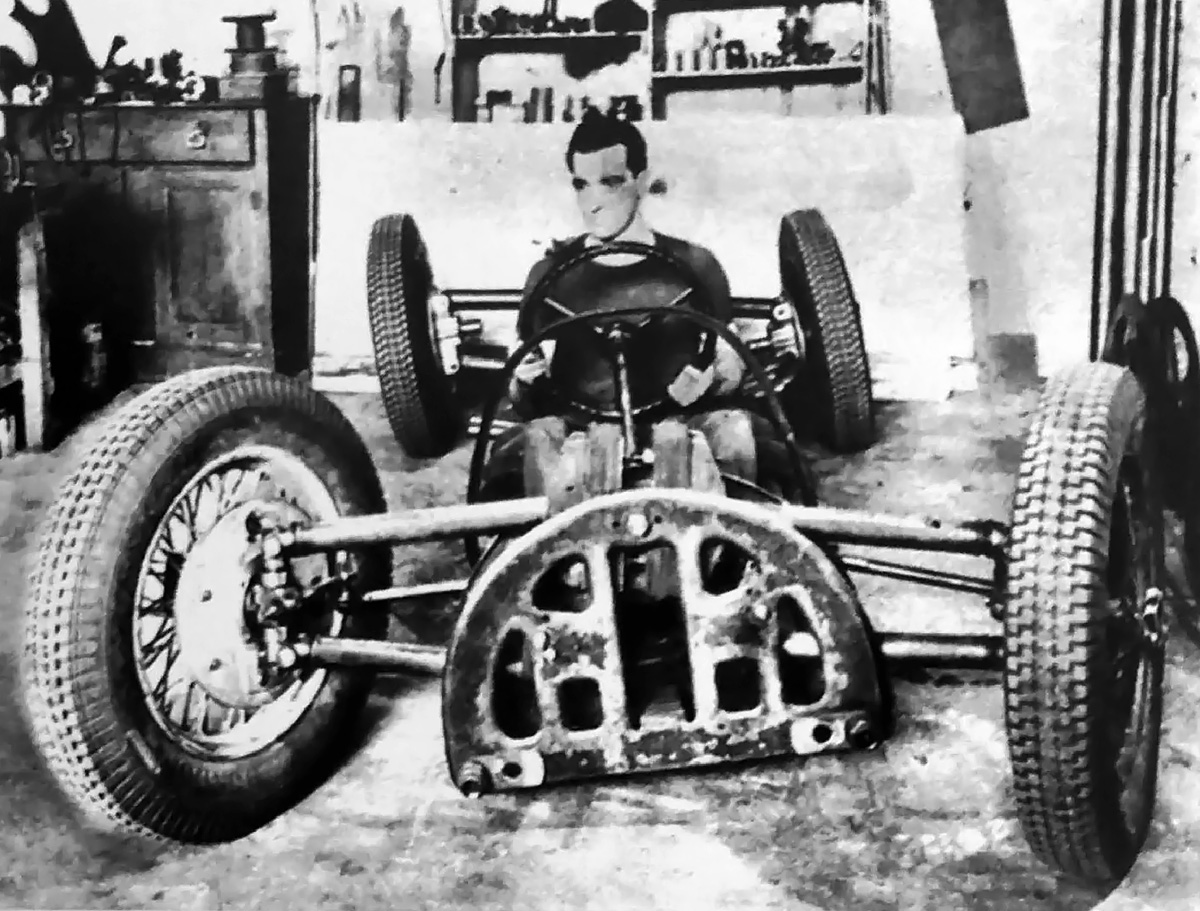
This picture appeared in a French newspaper in 1951. However, if Francois Guidobaldi is in the driver’s seat, he is much too young for the picture to have been taken in 1951. It is possible that the picture was taken much earlier and near the start of the car’s construction in 1939. Note the angle of the chassis and rear tires as they lean into the turn.
The driver sat in a low cockpit at the center of the car. The gas tank was located behind the cockpit and extended forward along both sides of the driver at the bottom of the cockpit. The engine was positioned between the fuel tank and the rear suspension mount. Mounts for the engine were clamped to the tubular frame rails. The three-speed transaxle with reverse gear was positioned under the rear suspension mount. At all four corners, the car had Bugatti knock-off wheels and Bugatti finned drum brakes.
Perhaps the only thing more unusual than the car’s leaning chassis was its engine. Guidobaldi designed, built, and installed into his car a two-stroke, eight-cylinder, air-cooled radial engine. The engine was placed horizontally (crankshaft was vertical) to get the car’s center of gravity as low as possible. From the drive side of the engine (under the car), a shaft extended forward to power two Roots-type superchargers built by Bugatti, and another shaft extended to the rear to power the transaxle. Two Guidobaldi-designed carburetors added the fuel. From the supercharger, the air and fuel mixture was delivered to the cylinders via intake manifolds under the car.

The “Guidomobile’s” engine package being tested. Laying a radial engine flat provided a low center of gravity, but it also complicated the drive arrangement. The two Bugatti superchargers on the left were driven via a single shaft from the engine. Note the individual exhaust stacks above the frame rail.
Intake and exhaust ports were on the drive side of the engine, facing the ground. An intake valve was positioned in each cylinder head and controlled via a rocker and pushrod by a cam ring atop the engine. The exhaust port was located on the cylinder just below the intake port. The flow of exhaust was controlled by the piston uncovering and covering the port. Exhaust from each cylinder flowed into an exhaust stack, with four stacks exiting horizontally on each side of the car. Two magnetos were mounted horizontally on the top (non-drive) side of the engine. Each magneto fired one of the two spark plugs mounted in the cylinder and flanking the intake valve. The engine was started via a remote starter engaged through the transaxle at the rear of the car.
The engine’s exact displacement is a bit of a mystery. One publication lists the bore and stroke as 2.36 in (60 mm), which would give a displacement of 83 cu in (1.36 L). However, many other publications state the engine’s displacement was either 61 or 67 cu in (1.0 or 1.1 L), which would result in a bore and stroke of approximately 2.17 in (55 mm). The engine was later enlarged to 91 cu in (1.5 L). If the bore and stroke were originally 2.36 in (60 mm), the bore would have been increased to 2.48 in (63 mm) to achieve a total displacement of 91 cu in (1.5 L). However, if the bore and stroke were originally 2.17 in (55 mm), then the bore would need to be increased to 2.60 in (66 mm) to reach a displacement of 91 cu in (1.5 L). It seems more reasonable to increase the bore of the air-cooled cylinders by .12 in (3 mm) than it does by .43 in (11 mm). Regardless of its actual displacement, the engine produced 180 hp (132 kW) at 6,500 hp in its original form. The engine’s power rating at 91 cu in (1.5 L) has not been found, but was presumably around 200 hp (147 kW). At some point after 1960, the two Bugatti superchargers were replaced by a single Roots supercharger of Guidobaldi’s own design.
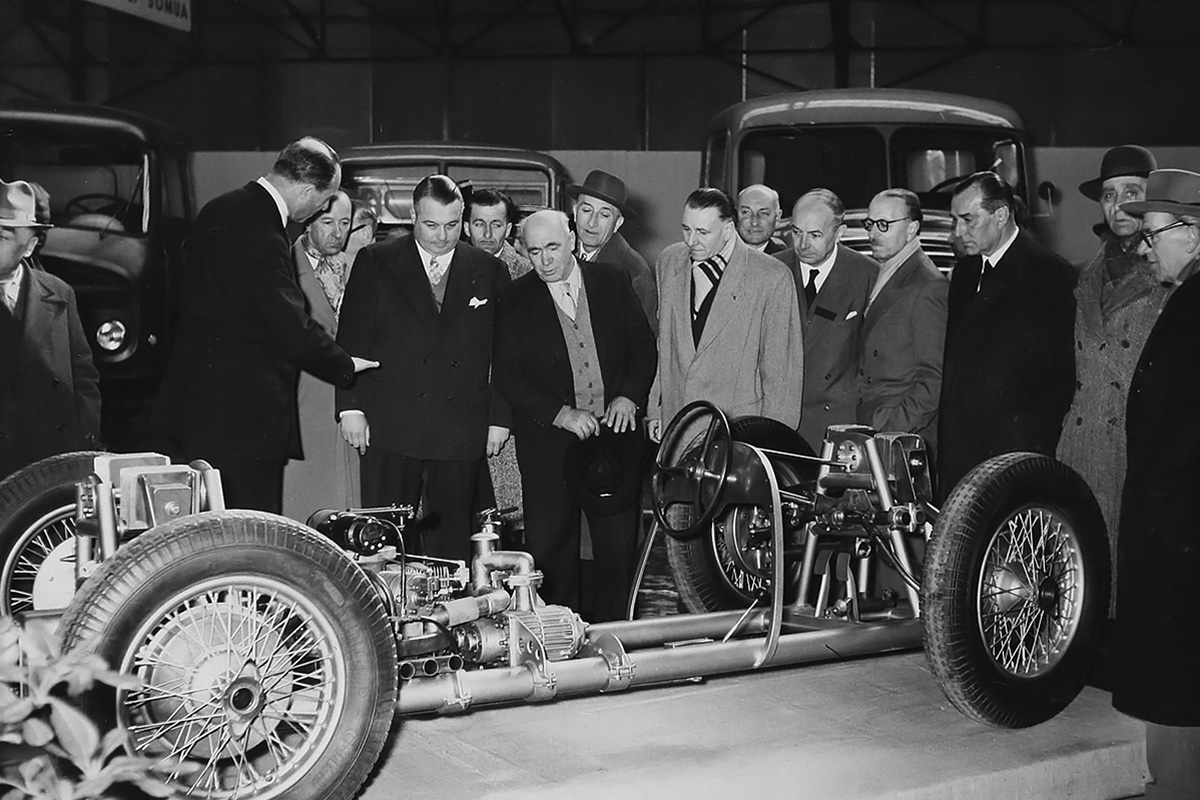
The bodiless “Guidomobile” on display at the Exposition Automobile de Nice in 1956. An aged Francois Guidobaldi stands at center holding his hat. The triangular suspension structures are apparent, as is the low-mounted engine. The circular mounts near the top of the suspension structures are the pivot points for the chassis, allowing it to swing.
Guidobaldi built the car almost entirely by himself, even making wooden cores to create clay molds for casting parts. The main structure of the chassis was seemingly complete by 1951, and the unbodied car was displayed at the Exposition Automobile de Nice in 1956. Some sources state the Guidobaldi undertook test drives in the late 1950s on the winding roads in the Maritime Alps. There are accounts that the car gave an unsettling ride while traversing curvy roads. The chassis would rise and fall as the suspension leaned back and forth, subjecting driver to movement in all directions. It is not clear when the aluminum body was added to the car, and no pictures of the original body have been found. A new body was constructed in 2010 when the car was restored. The new body reportedly follows the aesthetics of the original body, which had been badly damaged over the years.
The aluminum body built in 2010 covers the entire chassis. Large cutouts are present by each wheel to allow room for the suspension’s travel. A number of inlets provide ample cooling air to the engine. Air from the from grille passes through the entire body. A large scoop on each side of the car, just behind the front wheels, delivers cooling air to the engine. Two smaller scoops atop the engine cowling provide further cooling. A number of louvers behind the engine help the heated air leave the engine compartment. During the 2010 restoration, the exhaust stacks were lengthened and turned up 90 degrees to exit the top of the car’s sides.

Side view of Guidobaldi’s restored car illustrates the cooling air scoops just behind the front wheel and on the side of the engine compartment. Note the numerous louvers and vertical exhaust stacks. The fuel filler cap is just behind the driver’s headrest. (Cyril de Plater image)
Guidobaldi had always planned to build a passenger car using the same leaning chassis concept, but no such car was ever built. In the 1960s, a number of automobile manufacturers had an interest in Guidobaldi’s car. Perhaps the most interested was Mercedes-Benz, but negotiations failed to yield any agreement. Guidobaldi predicted his race car could achieve a top speed of 174 mph (280 km/h) and had eyed Formula 1 as a testing ground, but a lack of funds curtailed his aspirations. The expenses of building the car and filing patents left Guidobaldi with little extra money. On 6 August 1971, Guidobaldi passed away. His car had already been locked away and nearly forgotten.
In 1980, Antoine Raffaelli purchased the car from Guidobaldi’s son, Virgile. The car was then sold to Adrien Maeght in 1984. Maeght displayed the car at the Musée de l’Automobile à Mougins until the museum closed in early 2009. At that time, Guidobaldi’s car was purchased by David Humbert, who ordered a total restoration. Luc Franza completed the restoration to running order in 2010, and the restored “Guidomobile” debuted at the 8th Avignon Motor Festival in March. The car was then displayed at the Monaco Motor Show in June 2010 and in March 2014 at the
Concours d’Elegance du Monaco, where it won first prize in the technology category. Starting in September 2014, the car was displayed at the Cité de l’Automobile – Musée National, Collection Schlumpf in Mulhouse, France. In late 2019, and still in perfect condition, the “Guidomobile” was offered for sale. The vehicle serves as a lasting tribute to all engineers who chase their dreams.

Rear view of the “Guidomobile” shows the car with a slight lean into a right turn. Note the different angles of the left and right rear suspension arms. Just visible at the top of the car is the rubber damper system for the rear suspension. (Cyril de Plater image)
Sources:
– “Un mécanicien d’Antibes a réalisé cette monoplace de 180 Ch (Formule 1)” Supplement à l’Automobile N°107 (March 1955)
– “La voiture révolutionnaire de F, Guidobaldi” by Sven-Ake Nielsen, l’Automobile N°157 (March 1959)
– “The Leaning Car” by Sven-Ake Nielsen, Sportscar Graphic (April 1960)
– “Un rêve d’inventeur” by Dominique Pascal, Auto Passion N°6 (September 2006)
– “Un chef d’oeuvre ressuscité” by Philippe Loisel, La vie de l’Auto N°1424 (16 September 2010)
– “Road Vehicle Tilting Inwardly in Curves” US patent 2,791,440 by Francois Guidobaldi (granted 7 May 1957)
– http://s512186177.onlinehome.fr/
– https://www.hemmings.com/classifieds/cars-for-sale/classic/unspecified/2451178.html
– https://drivetribe.com/p/swaying-superstar-1956-guidobaldi-Ye7EN33pQFuOvZInPejodQ?iid=Kft1piUOT7OEPjWpIiuEHA