By William Pearce
Harold Caminez was born in Brooklyn, New York on 1 March 1898. He received a degree in Mechanical Engineering from Cornell University in 1919 and was awarded a master’s degree in 1920. After graduating from Cornell, Caminez worked as a civilian engineer for the United States Army Air Corps (AAC) Engineering Division at McCook Field in Dayton, Ohio.

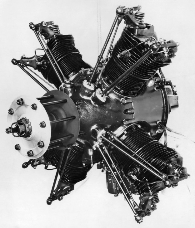
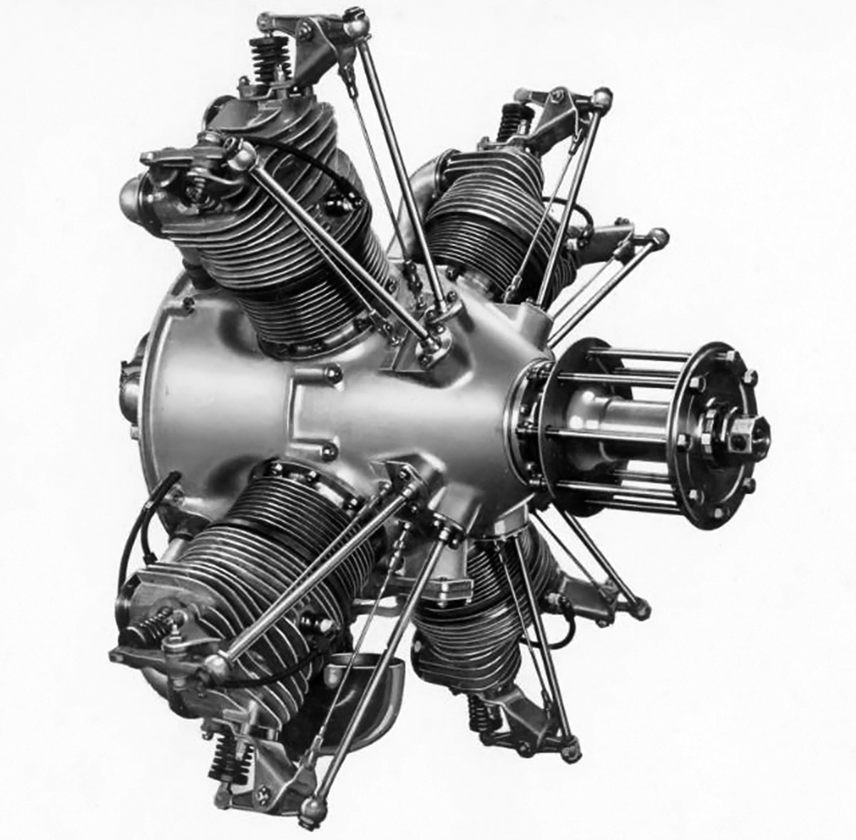
The Radial Cam Engine prototype was built-up quickly to test the cam-drive system, but the engine’s basic configuration carried on throughout the later Fairchild Caminez 447 series. Note the rocker arm setup, the large side-engine mount, and the long intake runners. (Aircraft Engine Historical Society image)
While at McCook Field, Caminez designed a new type of radial aircraft engine in which the crankshaft was replaced by a camshaft with two large lobes. The engine was called the Radial Cam Engine. The cam lobes contacted the pistons via a large roller bearing installed in the skirt of each piston. With the two lobes, each piston would go through four strokes (one of which was the power stroke) for every revolution of the camshaft, which would directly drive the propeller. Compared to a conventional radial, Caminez’s design would produce the same number of power strokes at half the RPM; this meant that the engine did not need a propeller gear reduction. In addition, the Radial Cam Engine design eliminated some 40 percent of the parts found in a conventional engine, making it much lighter than a conventional engine and possibly cheaper to manufacture. The Radial Cam Engine was seen as a potential replacement for the outdated yet abundant Curtiss OX-5 V-8 that was used at the time in many light aircraft. Caminez was able to gather enough interest in the Radial Cam Engine that the AAC supported construction of a prototype starting in 1923.
The Radial Cam Engine prototype had four cylinders placed at 90-degree intervals around the engine case. The barrel-type aluminum engine case was closed out by front and rear covers. The drive camshaft was supported by two main bearings—the rear main bearing was in the rear cover, and the front main bearing was in the engine case. The lobe assembly was machined separately from the camshaft and consisted of two lobes that were in the same plain. Despite a very similar appearance, the lobe profiles were different, with one lobe optimized for the compression and power strokes and the other lobe optimized for the exhaust and intake strokes. In addition, the leading side of the lobe was profiled to maximize thrust as it pushed the piston toward the combustion chamber, and the trailing side was profiled to keep the piston in constant contact with the lobe as the piston moved toward the camshaft. A splined hole at the center of the lobe assembly enabled its installation on the camshaft. Oil flowed through the hollow camshaft and into passageways within the lobe assembly. Two holes on the surface of each side of the lobe assembly sprayed oil within the engine and lubricated the piston roller bearings. The propeller mount engaged splines on the front of the camshaft, and the engine rotated clockwise when viewed from the rear.
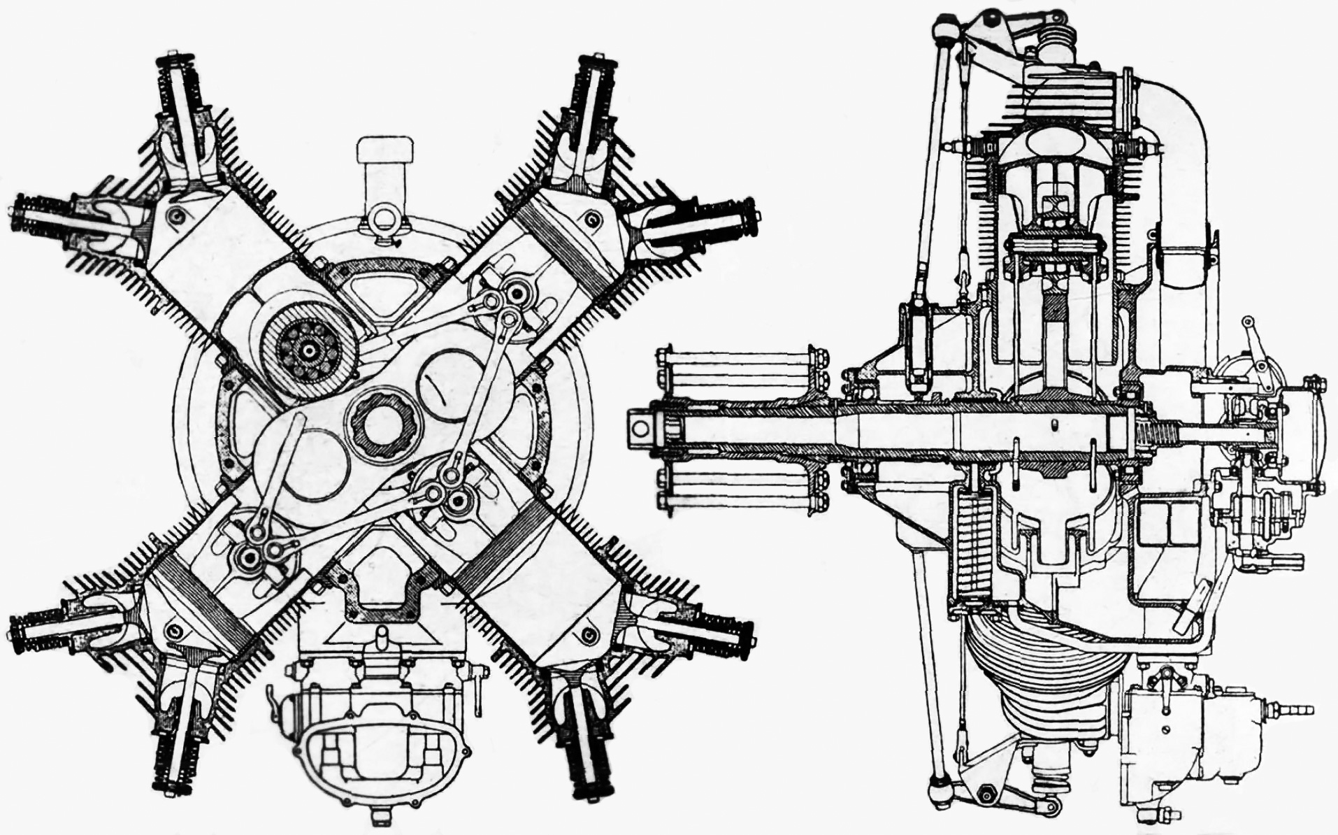
Drawings of the Fairchild Caminez 447-B, but all of the 447 engines had similar layouts. Note the general interaction of the camshaft, pistons with their roller bearings, and the link holders connecting the pistons. Starting with the 447-C, the link holders joined at a common point.
The large roller bearing in the skirt of each piston was secured by a piston pin. Via their bearings, the pistons drove the camshaft on the power stroke and were driven by the camshaft on the compression and exhaust strokes. For the intake stroke, the piston was pulled back toward the camshaft by to pairs of link holders that joined the piston to the pistons in adjacent cylinders. The link holders were mounted below and on each side of the roller bearing’s axis. Each link holder pair extended in front and behind the camshaft lobe to connect to an adjacent piston.
The air-cooled steel cylinders were attached to the engine case via a series of studs. Slots were cut into the bottom of the cylinder barrel to provide clearance for the link holders. Each cylinder had one intake valve and one exhaust valve, both of which were closed by volute springs. A sleeve containing two separate small lobes was keyed to the front side of the camshaft. These lobes drove roller followers that acted on pushrods to actuate the intake and exhaust valves. The pushrods extended vertically in front of the cylinder to exposed rocker arms mounted atop the cylinders. The intake port was at the rear of the cylinder, and the exhaust port was on the left side of the cylinder. The carburetor was mounted to an intake manifold at the rear of the engine, and the air/fuel mixture was delivered to each cylinder via separate intake runners. Each cylinder’s two spark plugs were fired by a battery-powered distributor driven from the rear of the engine.
The Radial Cam Engine prototype had a 5.625 in (143 mm) bore and a 4.50 in (114 mm) stroke. The engine displaced 447 cu in (7.33 L) and had a compression ratio of 5.59 to 1. Cylinder firing order was 1, 2, 3, and 4. The prototype engine’s forecasted performance was a maximum output of 220 hp (164 kW) at 1,500 rpm and 180 hp (134 kW) at 1,200 rpm. The engine had a 41 in (1.04 m) diameter and weighed 417 lb (189 kg).
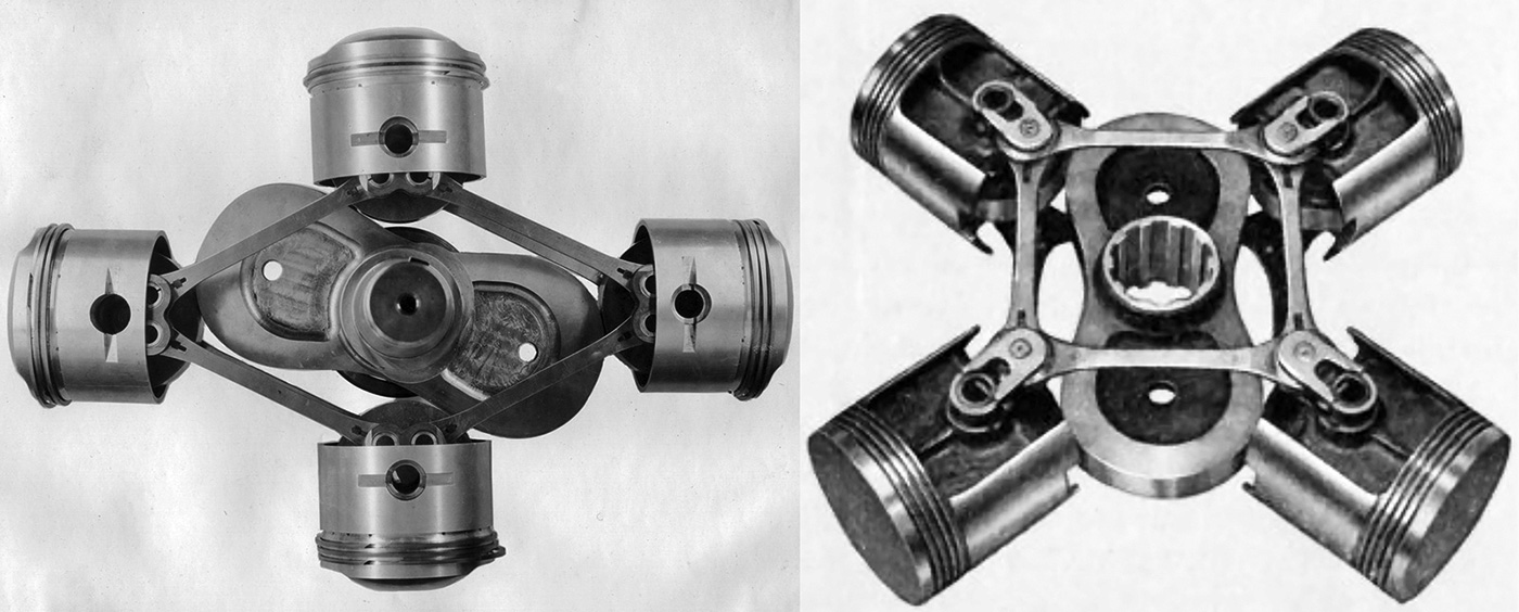
Left: Cam lobes, pistons, and link holders of the Radial Cam Engine prototype. Right: Cam lobes, pistons, and link holders of the 447-C. The piston design changed incrementally throughout the series, but the 447-C was the first to have the link holders join at a common point.
Some compromises existed with the Radial Cam Engine prototype. It was seen as a proof-of-concept engine, and weight was not a concern. The cylinders used were not designed specifically for the engine, and it was anticipated that they would be operating beyond their capabilities at full power. If the engine’s crankless design proved to be sound, then additional resources would be allocated to optimize engine components.
The prototype engine was completed in May 1924 and was installed on a later that month. Motoring tests were begun with the engine being powered by the . The tests revealed some weaknesses, and repairs were made. The Radial Cam Engine ran for the first time on 18 July 1924. During preliminary testing, many problems were encountered, most of which were tied to the engine’s excessive vibrations and overheating. The overheating was in part due to the inadequate cylinder design, but the other issues required modification of the engine. Through the first test sessions, the engine averaged about 105 hp (78 kW) at 880 rpm.
In August 1924, the Radial Cam Engine was rebuilt with a new engine case, new pistons, and many other improved components. The engine test cell was modified to incorporate a fan blowing air over the engine at 70 mph (113 km/h) to aid cooling. A second round of testing was run from September 1924 through February 1925. Again, numerous issues were encountered with nearly every part of the engine. However, the tests concluded that the engine’s camshaft drive operated well enough to warrant further development.
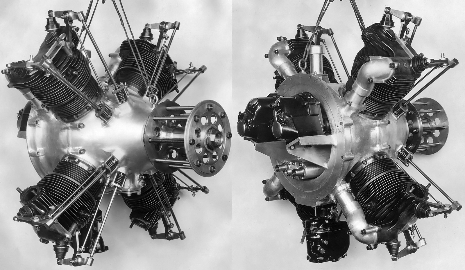
Front and rear views of the 447-A. Note the revised valve train and induction system compared to the prototype engine. Tie rods can be seen between the rocker bracket and the engine case. (Aircraft Engine Historical Society images)
Caminez had left the Engine Design Department and took a job as the Vice President and Chief Engineer of the Fairchild Caminez Engine Corporation, which was founded on 2 February 1925. Sherman Fairchild was an entrepreneur who founded Fairchild Aerial Camera Corporation in 1920 and Fairchild Aerial Surveys in 1921. Through the aerial camera business, Fairchild learned of Caminez and thought that his engine was exactly what civil aviation needed for the next generation of private and trainer aircraft. Fairchild was able to convince Caminez to partner together for the new venture, and the AAC was happy to have private industry take over development of the Radial Cam Engine. Fairchild also founded the Fairchild Airplane and Manufacturing Company later in 1925 to initially produce aircraft for aerial mapping.
With new support, Caminez redesigned the Radial Cam Engine, which became the Fairchild Caminez Model 447-A. While the bore, stroke, and operating principle of the engine remained unchanged, many improvements were incorporated into the new 447-A engine. A new two-piece engine case that was split vertically through the cylinders’ center line was developed. A flange around the rear of the engine case was used for engine mounting. The camshaft was now supported by three bearings: one on each side of the lobes and the third at the front of the engine. The valve train was altered to provide more room for the pushrods. A new spring provided tension for the pushrod against the roller follower. The placement of the rockers was altered to provide a better angle for valve actuation. A new support extended between the rocker mount atop the cylinder and the engine case. The carburetor was now mounted under the engine and delivered the air/fuel mixture to an internal manifold within the rear of the engine case. Individual runners extended along the backside of the cylinders to distribute the air/fuel charge into the cylinders. The induction system was designed so that each of the carburetor’s two barrels delivered air to cylinders located on opposite sides of the engine. New pistons were developed to provide better movement of the roller bearings and link holders. The cylinders were modified with slightly increased cooling fin area, and two magnetos driven from the rear of the engine fired the spark plugs.
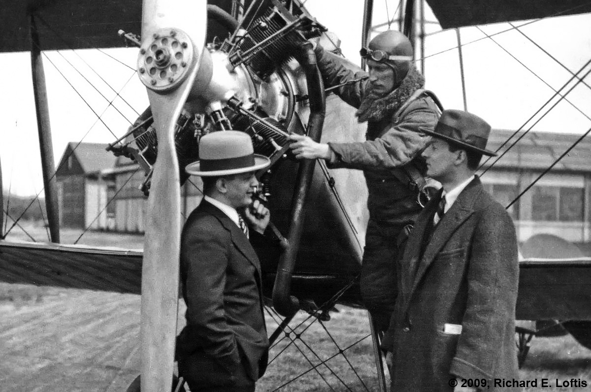
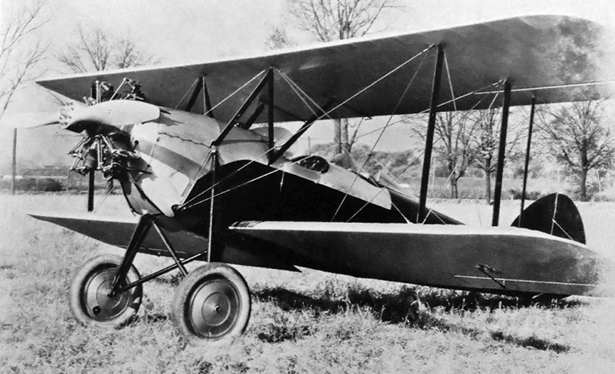
The modified 447-A engine with coil valve springs installed in an Avro 504 biplane. Harold Caminez is at left; pilot Richard Depew is at center; and Sherman Fairchild is at right. (Richard E. Loftis image via the Aircraft Engine Historical Society)
The 447-A was forecasted to produce 150 hp (12 kW) at 1,200 rpm, a substantial decrease in output compared to the original Radial Cam Engine estimates but an increase from what the prototype engine had actually achieved. The engine weighed 407 lb (185 kg). On 1 May 1925, the 447-A engine was delivered to the AAC Engineering Division for testing. The engine was motored from 9 May through 4 June, and many parts were found damaged and worn at the end of the test. The repaired engine was run under its own power between 17 June and 25 July in an attempt to pass a 50-hour type test. On top of many minor issues, vibrations and overheating were still a problem. There were also signs that the piston roller bearings were not staying in contact with the cam lobes and were causing some hammering to the lobes.
The engine was again repaired with improved parts, and another 50-hour test was attempted between 4 August and 15 September 1925. After 16 hours, the tests were halted and the engine was shipped back to Fairchild Caminez for repairs. Many valve train components had failed; the link holders were coming into contact with the cylinder cutouts, and the engine’s vibrations resulted in two broken propellers. The US Navy had similar results with a separate 447-A test engine that had been sent to them for testing.
Modifications were made to the 447-A, including switching out the volute valve springs in favor of coil springs. The modified 447-A was installed in an Avro 504 biplane for testing, and the combination made its first flight on 12 April 1926, flown by Richard Depew. This marked the first occasion that an aircraft was powered by a crankless engine.
The 447-B was refined from the 447-A. The valve train had again been updated; the cylinders had an aluminum head, and the exhaust port was moved to the back of the cylinder. Note the large brackets for the rocker arms.
The engine was reworked, resulting in the Fairchild Caminez 447-B. The engine case was modified and the valve train was revised. The rocker mounts were strengthened, and the springs adding tension between the pushrods and the roller followers were eliminated. The cylinders were redesigned with a cast aluminum cylinder head screwed and shrunk onto a steel barrel. An inner cylinder piston guide extended below the cylinder barrel. As its name implies, it helped guide the piston when it was at bottom dead center, but it also supported the piston during removal of the cylinder for servicing. Both the intake and exhaust ports were on the back side of the cylinder. The performance specifications of the 447-B were again reduced, with a maximum output of 135 hp (101 kW) at 1,050 rpm and 126 hp (94 kW) at 900 rpm. The engine had a compression ratio of 5.2 to 1 and weighed 360 lb (163 kg).
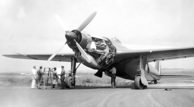
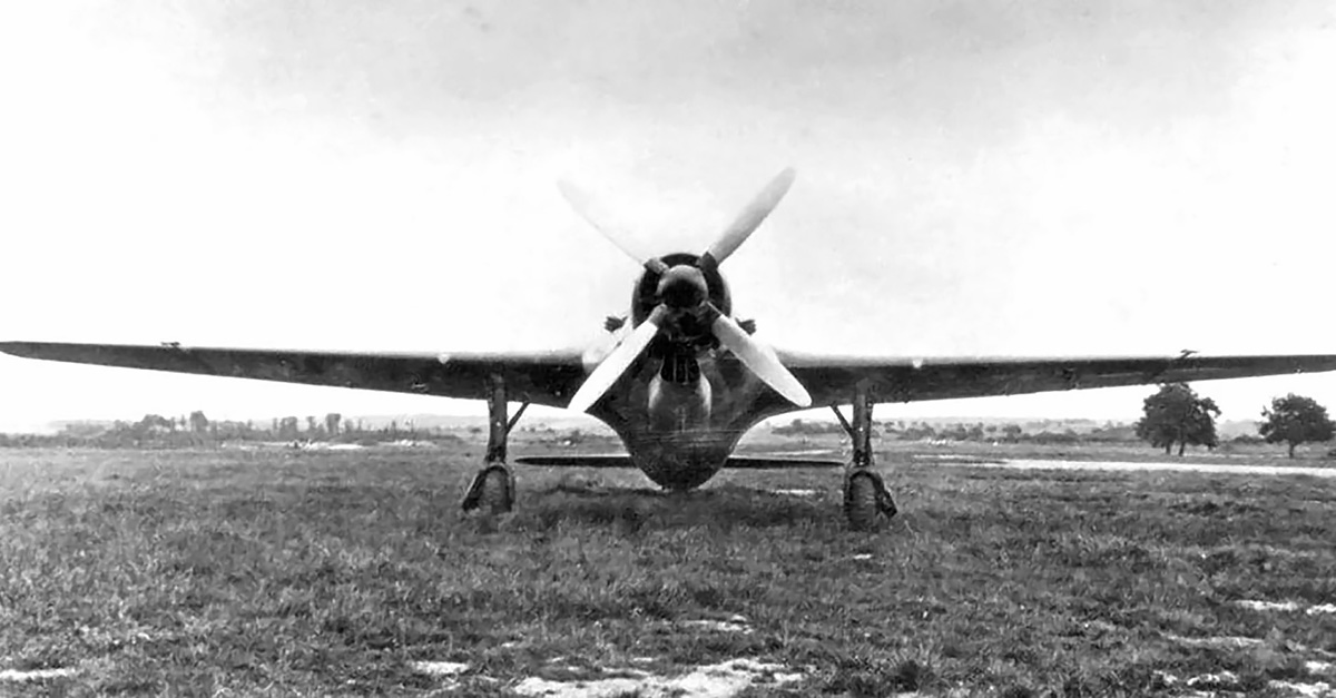
The Avro 504 was reengined with the 447-B, and other aircraft that were tested with engine include a Waco 10 biplane, a Fairchild FC-2W high-wing monoplane, and a Spartan C3 biplane. However, the 447-B engines were eventually removed due to vibration issues and overheating. It was found that the slow-turning engine necessitated a rather large propeller. A 10 ft (3.05 m) two-blade or an 8 ft 6 in (2.59 m) four-blade propeller was recommended, but the large diameter necessitated three-point takeoffs and landings for some aircraft. The propeller’s large hub and low rpm did not provide sufficient cooling airflow to the engine cylinders below 60 mph (97 km/h). The engine also had a tendency to fray and break the tips of the wooden propellers.
A Waco 10 with a 447-B engine. This aircraft was eventually fitted with a 447-C and was flown by Myron Gould “Dan” Beard for over 6,300 miles in the Ford Reliability Tour of 1928.
Again, the engine was revised, creating the 447-C. The engine case was updated. New pistons were designed with lower skirts that were notched to clear the cam lobe. The link holders were updated so that both rods on one side of the piston attached to the same point, just below the piston pin. Quality control was improved in an effort to prevent the occasionally poor machining that had plagued earlier engines. The Fairchild Caminez 447-C produced 145 hp (108 kW) at 1,100 rpm, 135 hp (101 kW) at 1,000 rpm, and 125 hp (93 kW) at 900 rpm. The engine had a 5.0 to 1 compression ratio and weighed 350 lb (159 kg). The 447-C had a length of 34 in (.86 m), a width and height of 36 in (.91 m), and a diameter of 41 in (1.04 m). Fuel consumption was .55 lb/hp/hr (334 g/kW/h) at full throttle and .48 lb/hp/hr (292 g/kW/hr) at cruise power.
The 447-C was installed in various aircraft for testing. including a Waco 10 biplane, a Travel Air 8000 (4000-CAM) biplane, a Kreider-Reisner Challenger C-2 biplane, and a Boeing Model 81 biplane trainer. Fairchild Caminez made efforts to market the engine commercially, and the engine underwent the Department of Commerce’s new process for an Approved Type Certificate (ATC). A 447-C engine was submitted for type certification testing in the spring of 1928. Engine output at the start and end of the 50-hour test were 119 hp (89 kW) at 960 rpm and 121 hp (90 kW) at 980 rpm respectively. As a result of the tests, the 447-C was officially rated at 120 hp (89 kW) at 960 rpm. The 447-C was the first engine to successfully complete the type certificate process, being awarded engine ATC No. 1 on 1 June 1928.

Once the 447-B fell short, production hopes fell on the 447-C. While the engine case was slightly updated, the primary changes to the 447-C were internal, with new pistons and link holders. (Aircraft Engine Historical Society image)
On 30 June 1928, a 447-C-powered Waco 10 and a Travel Air 8000 were two of 26 entries to compete in the Ford Reliability Tour of 1928. A 447-C-powed Kreider-Reisner Challenger C-2 also attempted to enter, but its engine and propeller were damaged on the delivery flight. The tour concluded on 28 July after covering 6,304 miles (10,145 km). The two 447-C-powered aircraft were able to complete the contest, but it took a traveling team of mechanics to keep the engines in good operating order. Approximately eleven propellers were needed to get the two aircraft to the finish line.
A two-row, eight-cylinder engine was built, but few details and no drawings or photos of the engine are known to exist. The second row of cylinders was directly behind the first, and the lobes for the two rows were staggered at 45 degrees on the camshaft. Most likely, the eight-cylinder engine shared as many common components as possible with the four-cylinder engine, but the bore and stroke are not known. Assuming the same 5.625 in (143 mm) bore and 4.50 in (114 mm) stroke were used, the eight-cylinder engine would have displaced 895 cu in (14.66 L). While the eight-cylinder engine ran smoother, it ran too hot, with the second row of cylinders overheating severely.
One final four-cylinder engine was designed, although it is not exactly clear when. The 447-D was the most advanced of the Caminez engines. The engine case was once again updated, this time to accommodate major changes to the cylinders and valve train. The cylinders had increased cooling fin area, and the valves were relocated. The exhaust valve and its pushrod were moved to the very front of the cylinder, and the intake valve and its pushrod were at the rear of the cylinder. An intake cam lobe was added to the rear of the camshaft, and all pushrods were enclosed in tubes. The rockers were enclosed and supported by the cylinder casting rather than by brackets bolted to the cylinder head, as used on earlier engines. The 447-D may have had an anticipated output of 145 hp (108 kW) at 1,000 rpm, but it is not known if the engine was tested or flown. The 447-D was approximately 29 in (.74 m) long and 39.5 in (1.00 m) in diameter.
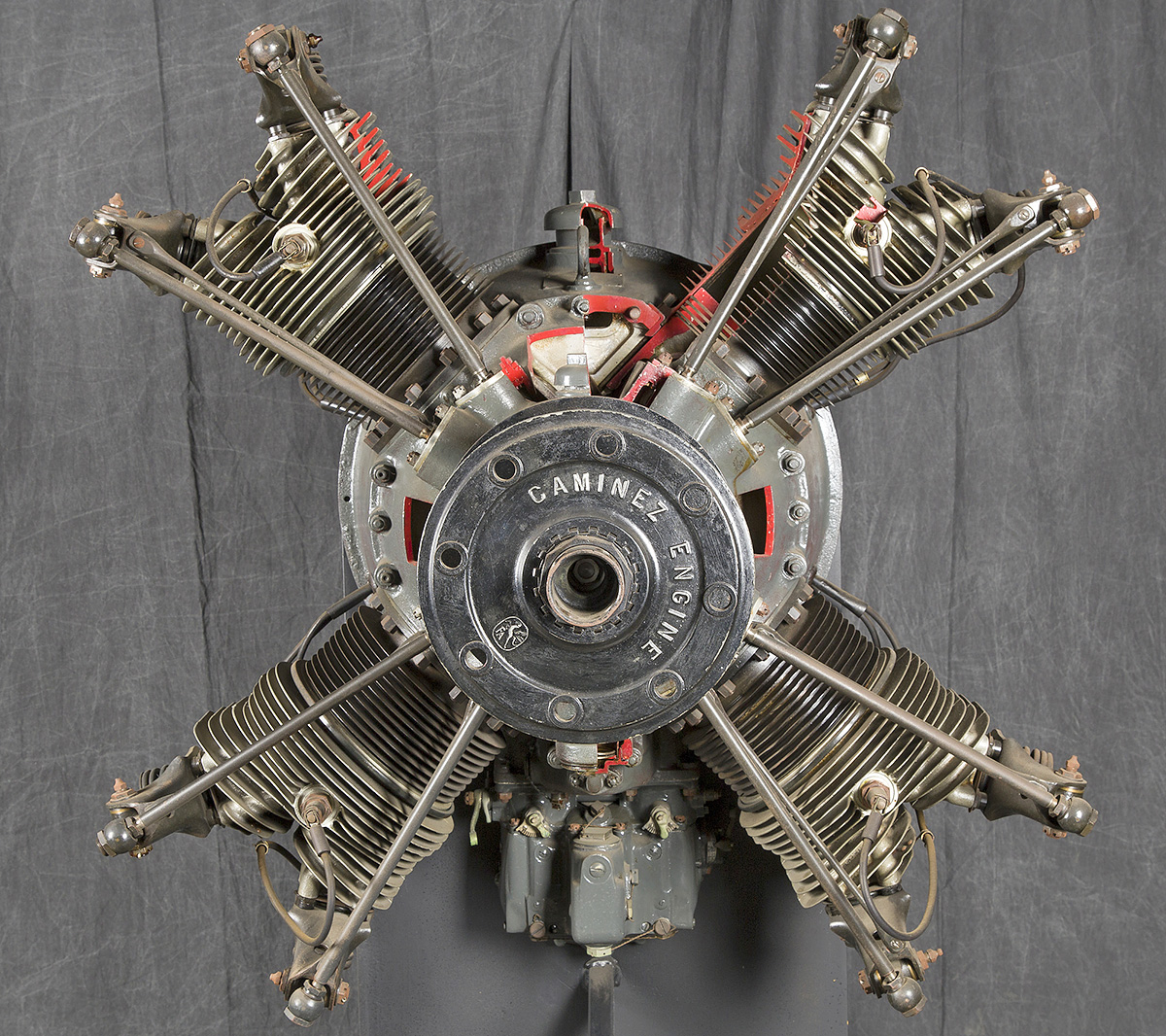
A Fairchild Caminez 447-C cutaway engine held at the Smithsonian National Air and Space Museum. Note the “Caminez Engine” and Fairchild logo stamped into the propeller hub. (NASM image)
For aircraft installations, the 447 engines needed to run around 600 rpm in order to keep the vibrations somewhat under control. Even so, engine vibrations continued to abuse the wooden propellers by breaking the tips or charring the holes around the attachment bolts. The aircraft also endured the abusive vibrations that relentlessly caused wires to snap or parts to loosen and fall off. By October 1928, only around 40 engines had been produced, with 10 being purchased by Japan and the rest used for testing. The Fairchild Caminez Engine Corporation conducted an independent assessment of the engine program, which concluded that some $2 million would be needed to fix the engine and bring it to production status. The company had already spent $800,000 and decided that it had spent enough. The cam-drive 447 engine program was cancelled in late 1928, and Caminez resigned from the company. The Fairchild Caminez Engine Corporation became the Fairchild Engine Corporation in May 1929, and work was soon initiated on what would become the inverted, air-cooled, six-cylinder, inline 6-370 engine.
Harold Caminez went on to do detailed design work on the Allison V-1710 V-12 engine in the early and mid-1930s, invented the Heli-Coil in the mid-1930s, and helped design the Lycoming XH-2470 H-24 and XR-7755 IR-36 engines in the late 1930s and early 1940s. On 28 July 1943, he and 19 others were killed in the crash of American Airlines Flight 63. Caminez was on a business trip for Lycoming when the Douglas DC-3 went down due to weather west of Trammel, Kentucky.
At least six Caminez 447 engines survive. Three 447-C engines are held in storage by the Smithsonian National Air and Space Museum: one is complete; one is a cutaway; and one is a motorized cutaway. The motorized cutaway was donated by the Fairchild Aviation Corporation and was most likely a display engine. Another 447-C is held by the Canada Science and Technology Museum in Ottawa, Canada. The Smithsonian also has a 447-D in storage. Another 447-D engine is on display at the Alfred & Lois Kelch Aviation Museum in Brodhead, Wisconsin.

The Fairchild Caminez 447-D engine was a complete redesign with a new engine case and new cylinders. The exhaust valve is on the front of the cylinder, while the intake valve is at the rear, and the rocker arms are completely enclosed. The design appears much more refined compared to the earlier 447 engines. (Richard E. Loftis image via the Aircraft Engine Historical Society)
Sources:
– “The Fairchild-Caminez Engine” by Paul Christiansen, Torque Meter Volume 7, Number 4 (Fall 2008)
– The Caminez Engine by the Fairchild Caminez Engine Corporation (circa 1928)
– Dyke’s Aircraft Engine Instructor by A. L. Dyke (1929)
– “Cam Engine” US patent 1,594,045 by Harold Caminez (filed 31 March 1924)
– “Piston” US patent 1,687,265 by Harold Caminez (filed 2 April 1927)
– “Internal-Combustion Engine” US patent 1,714,847 by Harold Caminez (filed 2 April 1924)
– Fairchild Aircraft 1926–1987 by Kent A. Mitchell (1997)
– The Ford Air Tours 1925 – 1931 by Lesley Forden (1972/2003)
– https://www.enginehistory.org/Biography/CaminezHarold/CaminezHarold.shtml
– http://enginehistory.org/Piston/Fairchild/Fairchild.shtml
– https://dmairfield.org/events/fordreliabilitytour/index.htm
– https://airandspace.si.edu/collection-objects/fairchild-caminez-447-c-radial-4-engine-cutaway/nasm_A19731576000
– https://airandspace.si.edu/collection-objects/fairchild-caminez-447-c-radial-4-engine/nasm_A19710915000
– https://airandspace.si.edu/collection-objects/fairchild-caminez-447-c-radial-4-engine/nasm_A19320038000
– https://www.enginehistory.org/id_unknown.shtml