
By William Pearce
On 25 February 1909, René Breton filed a French patent application for an internal combustion engine of a new configuration. For his design, Breton was awarded French patent 399,918 on 8 May 1909, and the patent was published on 10 July 1909. Breton was subsequently awarded British patent 4782 on 27 October 1910 and US patent 982,468 on 24 January 1911.

Sectional drawing from the Breton rotary engine patent. The three 160-degree Vee engine sections are visible, as are their crank disks. Planetary gears on the crank disk shafts meshed with a sun gear on the fixed central shaft and rotated the engine.
In his patent, Breton outlined a 12-cylinder, air-cooled, rotary aircraft engine designed to be compact and very light. The engine had a front and rear cylinder row, each with six cylinders. The cylinders of each row were arranged around the engine in three two-cylinder groups, with each two-cylinder group positioned 120 degrees around the center of the engine. Each two-cylinder group formed a 160-degree Vee twin. The front and rear rows were mirrored so that a front two-cylinder group matched with a rear two-cylinder group. Each front and rear cylinder was paired, fired simultaneously, and shared a common combustion chamber. The intake valve was on the rear side of the rear cylinder, and the exhaust valve was on the front side of the front cylinder.
The pistons of each two-cylinder, 160-degree Vee group were attached to a “crank disk” with fork-and-blade connecting rods. Each crank disk was built up from a shaft that ran on ball bearings and had a planet gear keyed at its center. The planet gear was sandwiched between the inner ends of front and rear disks, onto which the respective connecting rods were mounted. A front and rear outer disk closed out the basic assembly. The planet gears of the three crank disks engaged a sun gear mounted to a shaft at the center of the engine. Being a rotary engine, the central shaft was fixed to the airframe, and the engine rotated around the shaft. Each crank disk rotated four times for every revolution around the central shaft. With the propeller fixed to the front of the crankcase, the gearing meant that each four-stroke cylinder would fire twice before one revolution of the propeller/engine was completed.

Transverse drawing from the Breton rotary engine patent showing the connecting rods of a front and rear cylinder pair attached to the crank disk. At the center of the crank disk is the planetary gear.
Front and rear cam rings were mounted to the fixed central shaft to control the respective exhaust (front) and intake (rear) valves. The cam lobes on the cam ring actuated a lever that acted on a push rod to open the individual valves, each of which was held closed by a spring. The valve levers for the cylinder Vee groups were profiled, and the cam rings could slide on the central shaft. This combination allowed for certain Vee engine groups to be shut down by the cam rings sliding to achieve the desired interaction with the profiled valve levers. When an engine group was shut down, the intake valves were kept closed by the relocated intake cam ring missing the profiled intake lever, and the exhaust valves were kept open via a continuous collar on the relocated exhaust cam ring being in constant contact with the profiled exhaust lever. The cam rings would slide to positions in which they would operate either two, three, four, or six engine groups—respectively enabling either four, six, eight, or twelve cylinders.
As previously mentioned, the combustion chamber was shared by each front and rear cylinder pair. The combustion chamber was of a hemispherical design, but the cylinder head was of a “T” design with the underhead single intake valve and single exhaust valve on their respective sides of the cylinder pair. The patent drawings include a chamber at the rear of the engine that would distribute the air and fuel mixture from a carburetor to each cylinder pair via a manifold, but this induction system was not used on the prototype engine.

Another transverse drawing from the Breton rotary engine patent illustrating the common combustion chamber of the front and rear cylinder pair. The intake valve is on the left and the exhaust valve on the right. The fixed central shaft and its sun gear are at the center of the drawing. The cam rings are visible on the central shaft. At the bottom of the drawing is a crank disk with its two fans.
A centrifugal fan was mounted to each side of each disk crank assembly. A cover over the front side of each disk crank had a scoop that faced the direction of engine rotation and helped bring air into the fan. Air brought in would circulate through the crankcase and help cool engine’s internal components. The fan on the rear side of each crank disk would force the air out of the crankcase via an outlet that faced away from the direction of engine rotation. The patent proposes that some of the air warmed as it passed through the crankcase would be siphoned off to feed the induction chamber at the rear of the engine.
The prototype engine was very similar to what was described in the patent but differed mainly with the delivery of air and fuel into the cylinders. The internal fans no longer provided induction air, and there was no internal air chamber, carburetor, or intake manifolds. The prototype engine used fuel injection, with a pump for each cylinder pair controlled in a similar way as the valves. The fuel flowed through a line from the crankcase to each intake valve, and whatever injection pressure was present was amplified by the centrifugal action of the engine’s rotation. It appears air was drawn into the cylinder via openings in the intake valve housing.

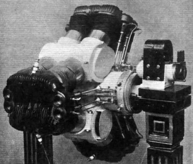
The Breton Rotary as displayed at the 1909 Salon de l’aéronautique. Note the four-cylinder head casting and the individual fuel lines. The internal air-cooling exit covers can be seen over the crank disks.
Few details of the prototype engine have been found, but it appears to consist of an aluminum crankcase with steel cylinder barrels. The cooling fins on the cylinder barrels were angled to match the engine’s rotation and to keep the fins parallel to the airflow. With each engine section made up of a 160-degree Vee, the two end pairs of cylinders converged together at a 40-degree angle. A single cast metal head was used to cover the four converging cylinders. A single spark plug was positioned in the center of each cylinder pair. The spark plugs were fired from a magneto attached to the aircraft and powered by a ring gear mounted to the rear of the engine. The rear of the fixed central shaft extended from the engine to provide a mounting point to attach the engine to the airframe.
The Breton rotary engine had a 3.23 in (82 mm) bore and a 3.35 in (85 mm) stroke. Total displacement from its 12 cylinders was 329 cu in (5.39 L). The engine produced 60 hp (45 kW) at 400 rpm, which means the crank disks were each rotating at 1,600 rpm. Sources indicate that the engine produced 20 hp (15 kW) on four cylinders, 30 hp (22 KW) on six cylinders, and 40 hp (30 kW) on eight cylinders. Maximum engine speed was stated as 500 rpm (2,000 rpm for the crank disks). The relatively small engine weighed only 198 lb (90 kg).
The engine made its debut in October 1909 at the Salon de l’aéronautique in Paris and had a selling price of 10,000 Francs. The engine appeared again at the 1910 Salon and was modified with two magnetos in place of the single unit originally fitted. After 1910, no further information has been found regarding the engine or its testing. A photo exists showing the engine in a somewhat neglected state. It is possible that the prototype engine survived (at least into the 1960s) stored in a museum or private collection.

The Breton engine as seen at the 1910 Salon. This view illustrates the cylinder cooling fin angles to match the engine’s rotation. The engine appears very similar to the 1909 version with the exception of new dual magnetos.
Sources:
– “Explosion-Motor” US patent 982,468 by René Breton (granted 24 January 1911)
– “Flight Engines at Paris Show” Flight (13 November 1909)
– “Aero Engines in the Paris Salon” The Aero (12 October 1909)
– Les Moteurs a Pistons Aeronautiques Francais Tome II by Alfred Bodemer and Robert Laugier (1987)
