Category Archives: Through World War I

REP 7-cylinder

R.E.P. Fan (Semi-Radial) Aircraft Engines

By William Pearce

Robert Esnault-Pelterie was born in France on 8 November 1881. In the early 1900s, he began experimenting with a glider modeled after the Wright Brothers’ glider of 1902. Esnault-Pelterie had experienced trouble with the Wrights’ wing warping technique and switched to ailerons in 1903. In 1906, Esnault-Pelterie began constructing a powered aircraft of his own design as well as an engine to power it. Esnault-Pelterie named the aircraft the R.E.P. 1 and it first flew in 1907. A new feature of the aircraft was a control stick, which Esnault-Pelterie patented. That patent made Esnault-Pelterie a rich man once royalties were paid after World War I. While the unique engine that he designed was the first in a family of engines known as R.E.P., their success would not endure like that of the control stick.

REP 7-cylinder

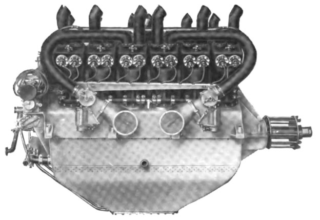
Front view of the R.E.P. seven-cylinder fan engine. Exhaust gases flowed out the holes around the top of the cylinders. The intake manifold can barely be seen behind the cylinders. In this view, the four cylinders on the right shared an intake manifold as did the three cylinder on the left.

Esnault-Pelterie’s first engine was an air-cooled, seven-cylinder fan engine. Sometimes referred to as a semi-radial, this engine had cylinders that were fanned-out on the top of the crankcase and not positioned around its entirety like a true radial. The cylinders were arranged in two rows—the front had four cylinders, and the rear had three cylinders. This configuration solved lower cylinder lubrication issues of radial engines, and air-cooling issues of inline engines.

The cast iron cylinders were attached to an aluminum crankcase. The upper part of the cylinder had cooling fins to dissipate heat. At the very top of the cylinder was a large, single valve. The valve was shaped like a piston and inverted, with the valve stem attached to underside of the head. When the valve was completely closed, a flange on its head would seat against the cylinder head and seal the cylinder. When the valve was partially open, exhaust gases flowed around the flange and escaped through ports in the cylinder head. When the valve was completely open, ports in its sides aligned with ports in the cylinder head to allow the intake mixture to flow into the cylinder.

REP 7-cylinder section

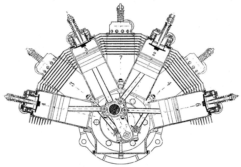
In this section view of the R.E.P. seven-cylinder engine, the cylinders are numbered by firing order. Cylinder 5 has the intake/exhaust valve completely closed. Cylinder 1 shows the valve partially open to allow exhaust gases to exit the cylinder. Cylinder 2 shows the valve completely open to allow the air/fuel mixture into the cylinder. Note the master/articulated connecting rod arrangement.

The valve was actuated by a rocker arm attached to the cylinder. The rocker arm was moved via a pushrod that was operated by a cam ring inside the engine. Each row of cylinders had its own cam ring positioned at the rear of the engine, and the cam rings had stepped lifts. The first step opened the valve part way to allow the exhaust gases to vacate the cylinder. The second, higher lift completely opened the valve to allow the fresh air/fuel mixture into the cylinder. For the intake, the cylinders were separated into left and right groups, with the left group (when viewing the engine from the rear) having an additional cylinder. Each group shared a common intake manifold with a carburetor attached to its end. The intake manifold was attached to the upper rear of the cylinder. Exhaust gases flowed out though ten holes around the cylinder’s top; there were no exhaust stacks.

A single spark plug was installed in the side of the cylinder and fired by an ignition coil powered by a battery. The pistons were made of steel and had two oil rings. They were attached to the connecting rods by trunnions bolted to the underside of the piston. The connecting rod for each row of cylinders had one master rod, and the rest were articulating rods. The crankshaft had two throws offset 180 degrees and was supported by two main bearings. To balance the crankshaft, Esnault-Pelterie left the crankpin solid for the row with an additional cylinder, and the crankpin for the row with one fewer cylinder was drilled hollow.

REP 10-cylinder side

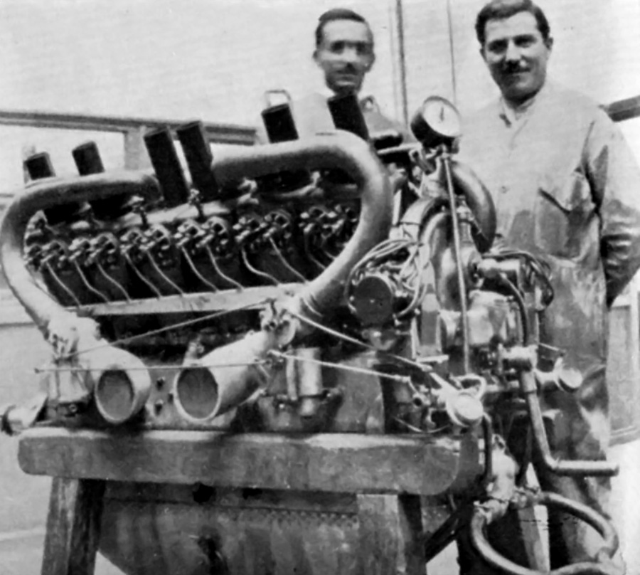
This side view of the R.E.P. 10-cylinder engine illustrates how it was comprised of two five-cylinder engines bolted front-to-front. Note the rocker arm arrangement and the single valve. The pictured engine was equipped with magnetos.

The engine had a 3.35 in (85 mm) bore and 3.74 in (95 mm) stroke. The seven cylinders displaced a total of 230 cu in (3.8 L). The engine produced 30 hp (22 kW) at 1,500 rpm and weighed 150 lb (68 kg). A five-cylinder version was also built with three cylinders in the first row and two in the second. It produced 20 hp (15 kW) at 1,500 rpm from its 164 cu in (2.7 L) and weighed 118 lb (54 kg). Another version consisted of two five-cylinder engines joined at their front to create a 10-cylinder engine. Each engine group had its own intake manifold feeding five cylinders. The 10-cylinder engine produced 50 hp (37 kW) at 1,500 rpm from its 329 cu in (5.4 L) and weighed 214 lb (97 kg). Some sources indicate the same coupling treatment was applied to the seven-cylinder engine to create a 14-cylinder engine, but this cannot be confirmed. A 14-cylinder engine would have displaced 461 cu in (7.5 L) and produced around 70 hp (52 kW).

The five- and seven-cylinder engines powered a number of early aircraft (R.E.P.s, Bléroits, Kapferer-Paulhans, and Breguets), but it is unlikely the 10-cylinder engine ever flew. Esnault-Pelterie received an award in 1908 from the Société des ingénieurs civils de France (Society of Civil Engineers of France) for his seven-cylinder R.E.P. engine. However, the cylinder’s single valve proved unsatisfactory, and the engines were redesigned in 1909.

REP 10-cylinder back

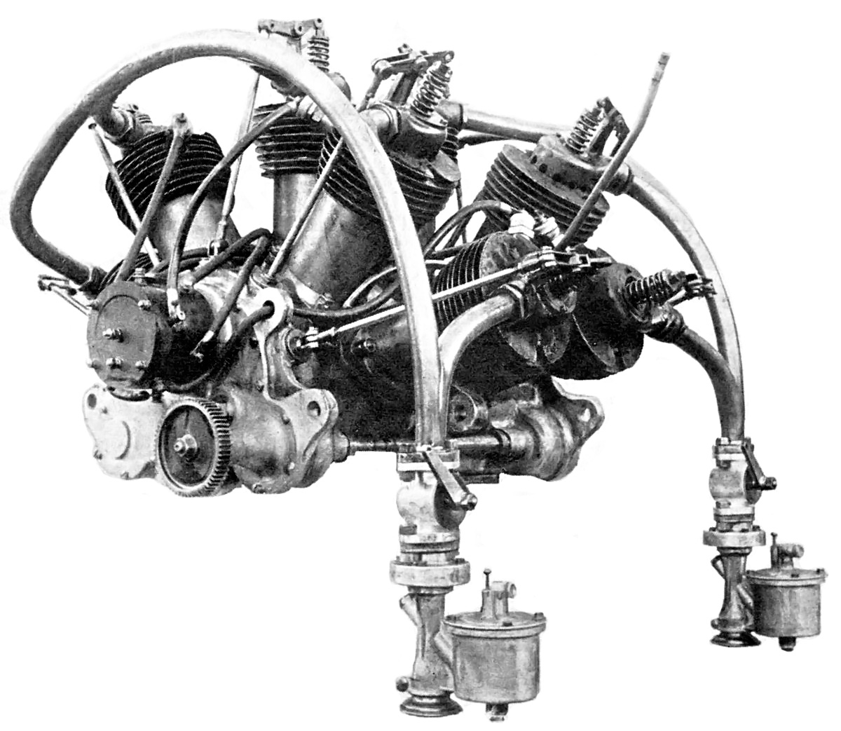
Rear view of the R.E.P. 10-cylinder engine equipped with a coil ignition. Note that each engine section has its own intake manifold and carburetor.

The updated engines had two valves per cylinder, but they were still operated by a single rocker arm. The intake valve was in the front of the cylinder, and the exhaust valve was in the rear. The rocker arm pivoted between the valves so that it pushed the intake valve open and then rocked back to pull down on the exhaust valve to open it. This was achieved by a grooved cam-disc that could “pull” and “push” the pushrod.

The engine’s bore and stroke were increased to 3.94 in (100 mm) and 5.51 in (140 mm). The five-cylinder engine displaced 335 cu in (5.5 L) and produced 60 hp (45 kW) at 1,400 rpm. The seven-cylinder engine displaced 470 cu in (7.7 L) and produced 90 hp (67 kW) at 1,400 rpm. There is no indication that any attempt to couple the engines was made. The cylinders had revised cooling fins, and the spark plug was repositioned to the cylinder head. Magnetos were used in place of the coil ignition.

REP 5-cylinder Type D

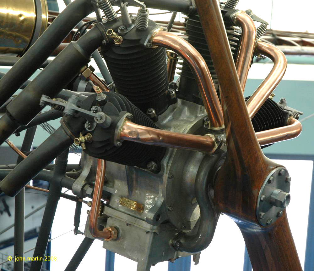
An updated R.E.P. five-cylinder engine preserved in a R.E.P. Type D monoplane at the Musée de l’Air et de l’Espace. Note the two valves per cylinder and rocker arm arrangement. The unique induction system can be seen in which it drew air from the crankcase and delivered it to the cylinders via the copper pipes. The individual exhaust pipes can be seen at the rear of the engine. (John Martin image via the Aircraft Engine Historical Society)

Induction and exhaust were also updated. Intake air was fed from the crankcase (where it was warmed), through a distributor, and then to the front of each cylinder. Exhaust gases were collected in pipes at the rear of each cylinder and directed away from the cockpit. The many changes increased the weight of the engines to 243 lb (110 kg) for the five-cylinder and 287 lb (130 kg) for the seven-cylinder. The updated R.E.P. fan engine had no trouble running for 10 hours non-stop during various bench tests.

The five-cylinder engine seemed the more successful of the two and was installed in a number of aircraft (R.E.P.s and Farman-Neubauers). It was used in the Vickers R.E.P., which was the first aircraft made by Vickers and would have been the first aircraft to fly in Antarctica had its wings not been damaged during a demonstration flight in Australia. Even so, the wingless Vickers was taken to Antarctica and used as a powered sled, but with not much success. The remains of this aircraft were rediscovered there in January 2010.

Vickers REP in Antarctica

The Vickers R.E.P. in Antarctica in 1911. The engine clearly has two valves per cylinder and the unique induction system of the updated fan engine.

In 1911, Esnault-Pelterie refocused his design efforts on true radial engines, constructing five- and seven-cylinder engines. The fan/semi-radial engines were phased out in 1912. Over the next few years, Esnault-Pelterie stopped designing piston engines as he became more interested in rocketry. A few R.E.P. fan engines still exist in museums, including a seven-cylinder engine in Esnault-Pelterie’s original R.E.P. 1 aircraft from 1907 displayed at the Musée national des Arts et Métiers (National Museum of Arts and Crafts) in Paris, France. This museum may also hold another original seven-cylinder engine cutaway. An updated five-cylinder engine exists installed in an uncovered R.E.P. Type D monoplane from 1910 at the Musée de l’Air et de l’Espace (Air and Space Museum) in Le Bourget, France.

Note: Many sources list a variety of different bore and stroke combinations for the R.E.P. fan engines. Some sources list some of the early engines as having a 3.54 in (90 mm) stroke, while others list the updated engines as having a 4.33 in (110 mm) bore or 6.30 in (160 mm) stroke. While it is possible that such bore and stroke combinations were built, little supporting information has been found.

REP 1 with 7-cylinder engine

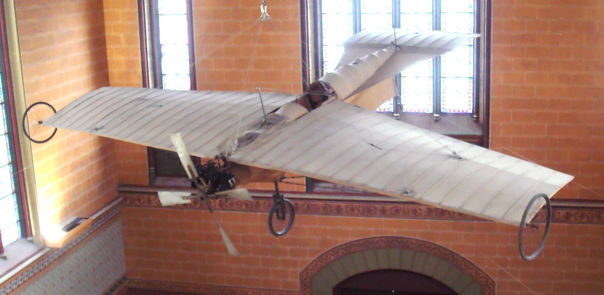
Esnault-Pelterie’s original R.E.P. 1 aircraft and its engine preserved in the Musée national des Arts et Métiers. (PHGCOM image via Wikimedia Commons)

Sources:
– “Moteur Extra-Léger a Explosion” by Robert Esnault-Pelterie, Mémoires et Compte Rendu des Travaux de la Société des ingénieurs civils de France Bulletin (December 1907)
Les aéroplanes et moteurs R.E.P. by Gérard Hartmann (4 MB pdf)
Les Moteurs a Pistons Aeronautiques Francais Tome I by Alfred Bodemer and Robert Laugier (1987)
– “The First Paris Aeronautical Salon: Engines for Aeroplanes” Flight (16 and 23 January 1909)
Aero Engines by G. A. Burls (1916)
http://aviatechno.net/bib/001n_les_moteurs_aviation.php
http://www.nmspacemuseum.org/halloffame/detail.php?id=7
http://en.wikipedia.org/wiki/Vickers_R.E.P._Type_Monoplane

Lancia V-12 aircraft engine side

Lancia Tipo 4 and Tipo 5 V-12 Aircraft Engines

By William Pearce

Vincenzo Lancia was born near Turin, Italy in 1881. From an early age, he demonstrated an aptitude in mathematics, and his father encouraged him to become an accountant. However, Lancia was mainly interested in machinery and engineering. By the age of 17, he worked as a bookkeeper for a small bicycle and auto repair shop, operated by the Ceirano brothers. There, he became more of a mechanic’s assistant than a bookkeeper. When the shop built an automobile, FIAT bought the business and made Lancia, who was only 19, chief inspector of their new factory and also a test driver. His driving skills impressed FIAT, and they later made him a race car driver.

Lancia V-12 aircraft engine

The Lancia Tipo 4 V-12 aircraft engine displaying its individual cylinders and distinct valve train. The engine was configured for pusher installations, which is why exhaust was expelled toward the propeller.

But Lancia wanted to design. In 1906, at the age of 25, he and another FIAT worker founded their own car company: Lancia & Company. Lancia and his company produced a number of vehicles and engines and became known throughout Europe. Always experimenting and innovating, Lancia took out patents for a narrow Vee engine configuration and an offset crankshaft in 1915. World War I interrupted plans to use the design for an automotive engine but gave Lancia incentive to build an aircraft engine.

Known as the Tipo 4 (Type 4), the Lancia V-12 aircraft engine was water cooled and had a 50-degree angle between the cylinder banks. The engine’s individual steel cylinders were mounted to its aluminum crankcase, with a deep oil pan. Each cylinder had one intake and one exhaust valve perpendicular to the cylinder axis. These horizontal valves opened into a small, rectangular clearance space above the cylinders that extended the combustion chamber above the piston. The valves were actuated by long rocker arms positioned in the Vee of the engine. A single hollow camshaft positioned in the middle of the Vee acted upon the rocker arms. The camshaft was driven from the crankshaft at the rear of the engine. The valve train was very similar to that later used on the Duesenberg Model H aircraft engine.

Lancia V-12 aircraft engine stand

Two technicians stand next to the Tipo 4 engine. Note the straight exhaust stacks. This is thought to be the prototype Tipo 4, and it closely resembles the engine that is preserved in the FIAT/Lancia archives.

Each cylinder had two spark plugs that were positioned on the opposite side from the valves. Two magnetos were located at the rear of the engine, each firing one spark plug per cylinder. One of the magnetos could be replaced by a distributor. Two Claudel-Lancia carburetors were mounted on each side of the engine. Each carburetor supplied air to three cylinders via a manifold that looped above the cylinders. A section of the intake manifold was jacketed to use engine cooling water to heat the air/fuel mixture as it traveled to the cylinders. Exhaust was expelled via a short manifold extending above each cylinder.

The hollow crankshaft had six throws and used a side-by-side connecting rod arrangement. However, to compensate for the odd Vee angle, each cylinder had its own crankpin that was slightly offset (displaced) from the crankshaft’s center. Cast aluminum pistons and pressure lubrication were used. Cooling water was pumped into the jacket around each cylinder’s barrel via manifolds on each side of the engine. The water then flowed up into the cylinder head and finally into a manifold that took it back to the radiator.

Lancia V-12 aircraft engine side

Side view of the Lancia Tipo 4 illustrating the two carburetors and intake manifolds on the side of the engine. Note the two spark plugs for each cylinder.

The Tipo 4 had a 4.75 in (120.7 mm) bore and a 7.09 in (180 mm) stroke. Many sources state the bore was 4.72 in (120 mm); however, all primary source material from Lancia indicates the bore was 120.7 mm (4.75 in). The engine’s total displacement was 1,508 cu in (24.7 L). It produced 320 hp (237 kW) at 1,380 rpm and 380 hp (283 kW) at 1,420 rpm. The Tipo 4 engine was direct drive and weighed 740 lb (335 kg).

Lancia V-12 aircraft engine top

A good view of the Lancia Tipo 4 showing the two magnetos, open gear train, coolant manifolds, and hand crank at the rear of the engine used for starting.

The Tipo 4 aircraft engine was built in 1916. It was installed in the Caproni Ca 37 and Ca 38 aircraft. These relatively fast aircraft were light-bomber / ground attack prototypes. The Ca 37 flew in 1916, and the Ca 38 was a more refined version of the aircraft that flew in 1917. Neither aircraft entered production, and it is not clear if the Tipo 4 engine was installed in any other types.

At least one Tipo 4 engine was shipped to the United States in late 1917. Thomas Evarts Adams, Inc represented Lancia & Company in New York and initiated the process of producing the engine in the United States. The engine was on display until early 1918 when it was sent to McCook Field, Ohio for testing by the US government. The Tipo 4 was tested in May and July 1918 and did not develop the anticipated power. On test, the Tipo 4 produced 279 hp (208 kW) at 1,250 rpm and 305 hp (227 kW) at 1,400 rpm. Plans for producing the Lancia Tipo 4 V-12 never moved forward. The end of World War I caused a large influx of surplus aircraft engines that left aircraft engine manufacturers with a very small market. In addition, the US government was interested in the more powerful Tipo 5 (Type 5) engine that Lancia was designing. A Tipo 4 engine is preserved in the FIAT/Lancia Archives in Turin, Italy.

Caproni Ca37 Lancia Tipo 4

The Caproni Ca 37 was the first aircraft powered by the Lancia Tipo 4 V-12 engine. The Ca 37 first flew in the summer of 1916. Note the engine’s exhaust tips. The Ca 37 had a top speed of 103 mph (165 km/h.)

The design for the Lancia Tipo 5 V-12 engine was well underway by the end of 1918. The Tipo 5 was very similar to the Tipo 4; however, there were a number of differences between the two engines. The Tipo 5 had a larger bore and a 53-degree angle between its cylinder banks. The Tipo 5 did not have offset crankpins; the engine used an early style of a fork-and-blade connecting rod design. The straight fork rod was relatively thick, and this size allowed the blade rod to connect to the same crankpin via a cut-out section of the fork rod. The Tipo 5 did not have the deep oil pan like the Tipo 4. The Tipo 5 had a 5.91 in (150 mm) bore and a 7.09 in (180 mm stroke). The engine’s total displacement was 2,329 cu in (38.2 L), and it was forecasted to produce approximately 600 hp (447 kW) at 1,700 rpm. The Tipo 5 weighed 992 lb (450 kg). No verifiable proof has been found that a Tipo 5 engine was ever built.

Caproni Ca 38 front

The Caproni Ca 38’s fuselage and tail booms were more rounded and streamlined compared to those of the Ca 37, but the aircraft were otherwise very similar. The Ca 38 flew in 1917 and had a top speed of 106 mph (170 km/h). The Ca 37 and Ca 38 never entered production. They are the only known applications of the Lancia Tipo 4 engine.

Through the early 1920s, Lancia designed at least two additional V-12 engines for automotive use, one of which had a cylinder bank angle of 14 degrees (connecting rod angle was 22 degrees). None of the V-12 engines entered production. However, these engines led to a range of narrow V-8s and V-4s that Lancia produced starting in the 1920s. Narrow V-4 types were in production until the 1960s.

Lancia V-12 aircraft engine Section

Sectional view of the Lancia Tipo 5 V-12 aircraft engine showing a 53-degree angle between the cylinder banks. Note the long rocker arms, horizontal valves, and small space above the combustion chambers. This configuration was very similar to the Tipo 4 and early Duesenberg engines.

Sources:
– Correspondence with Geoff Goldberg, Lancia Historian
Textbook of Aero Engines by E. H. Sherbondy and G. Douglas Wardrop (1920)
Aerosphere 1939 by Glenn Angle (1940)
– “To Build Lancia Airplane Engine,” Automobile Topics (17 November 1917)
Air Service Handbook by Iskander Hourwich (1925)
Los Motores Aeroespaciales: A-Z by Ricardo Miguel Vidal (2012)
The V-12 Engine by Karl Ludvigsen (2005)
Aeroplani Caproni by Rosario Abate, Gregory Alegi, and Giorgio Apostolo (1992)
Gli Aeroplani Caproni by Gianni Caproni (1937)
http://www.sportscars.tv/Newfiles/histlancia.html

Duesenberg Aircraft Engines: A Technical Description

By William Pearce

The Duesenberg name became legendary in early auto racing and is now known around the world as one of the most sought after classic cars. For a brief period, encompassing World War I, Fred and Augie Duesenberg turned their attention to aircraft engines. In the span of five years, their company created four unique aircraft engines and was involved in the development of others.

Duesenberg Aircraft Engines: A Technical Description contains over 100 illustrations and describes the aircraft engines from this nearly forgotten chapter in Duesenberg and aviation history.

Contents:

Preface
1.  Fred and Augie Duesenberg
2.  Duesenberg “Walking Beam” Valve Gear
3.  Straight-Four Engine of 1915
4.  V-12 Engine of 1916
5.  Sixteen-Valve Straight-Four Engine
6.  The King-Bugatti U-16 Engine
7.  Duesenberg Model H V-16 Engine
Epilogue
Appendix A – Duesenberg Aircraft Engine Comparison
Appendix B – Duesenberg Valve Gear Patent
Appendix C – The King V-12 Aero Engine
Appendix D – Duesenberg Engine Test House
Appendix E – Christensen Self-Starter
Appendix F – Notes on Descriptions and Conflicting Information
Bibliography

$12.99 USD
Softcover
6 in x 9 in
112 pages (122 total page count)
ISBN 978-0-9850353-0-3

Duesenberg Aircraft Engines: A Technical Description is available at Amazon.com. If you wish to purchase the book with a check, please contact us for arrangements.

Sample Pages:
Duesenberg Aircraft Engines sample Duesenberg Aircraft Engines sample Duesenberg Aircraft Engines sample.

.

.


The revisions below are formatted to be printed and added to your copy of Duesenberg Aircraft Engines. Check the revision number on the copyright page and download any new revisions.
Revision 20130329
Revision 20150122

Duesenberg Motors New York Aero Show

A recently discovered image of the Duesenberg Motors Corporation display at the New York Aeronautical Exhibition, held in Madison Square Garden from 1 to 15 March 1919. From left to right is a complete King-Bugatti U-16 engine built by Duesenberg, the Duesenberg Model H V-16 engine with gear reduction, the sixteen-valve four-cylinder Duesenberg engine with gear reduction, and a partially assembled King-Bugatti engine.