Category Archives: World War II

kawasaki-ki-64-engine-run

Kawasaki Ki-64 Experimental Fighter

By William Pearce

In the late 1930s, designers at Arsenal de l’Aéronautique in France began working on a new fighter powered by two engines installed in tandem. One engine was positioned in front of the cockpit, and the other engine was behind the cockpit. Each engine drove half of a coaxial contra-rotating propeller. This design was eventually developed into the Arsenal VB 10. Takeo Doi was a Japanese designer at Kawasaki and was aware of Arsenal’s tandem-engine design.

kawasaki-ki-64-hangar

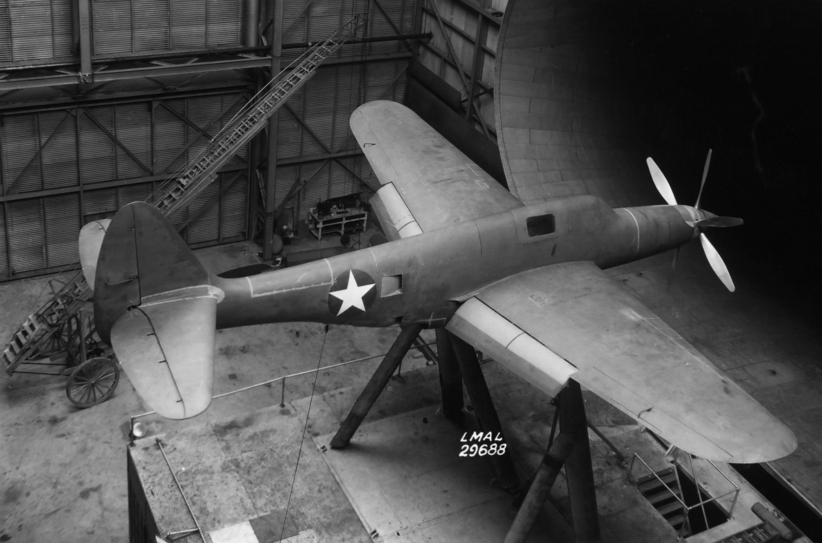
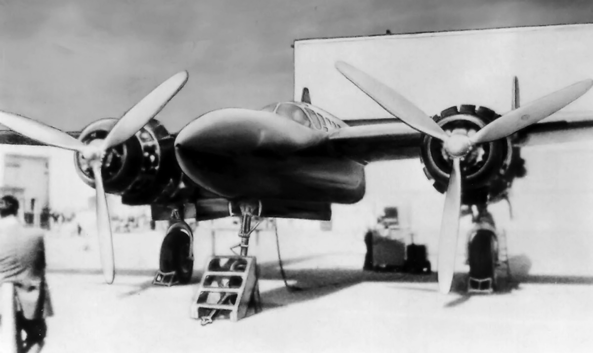
The Kawasaki Ki-64 fighter undergoing gear retraction tests in a hangar in Gifu. Note the exhaust stacks for the front engine and the dorsal air intake scoop for the rear engine.

Doi was also aware of the evaporative cooling system used on the German Heinkel He 100. Japan had sent a delegation to Germany in December 1938 that successfully negotiated the purchase of three He 100 and two He 119 aircraft. The He 100s were delivered to Japan in the summer of 1940.

In 1939, Doi began to contemplate a high-speed fighter for the Imperial Japanese Army Air Force that used tandem engines and evaporative cooling. At the time, the Japanese aircraft industry was more focused on conventional aircraft, and Kawasaki and Doi were busy with designing the Ki-60 and Ki-61 Hien (Swallow, or Allied code name “Tony”) fighters. In October 1940, Kawasaki and Doi received support for the tandem-engine fighter project, which was then designated Ki-64 (Allied code name “Rob”). The aircraft’s design was refined, and a single Ki-64 prototype was ordered on 23 January 1941.

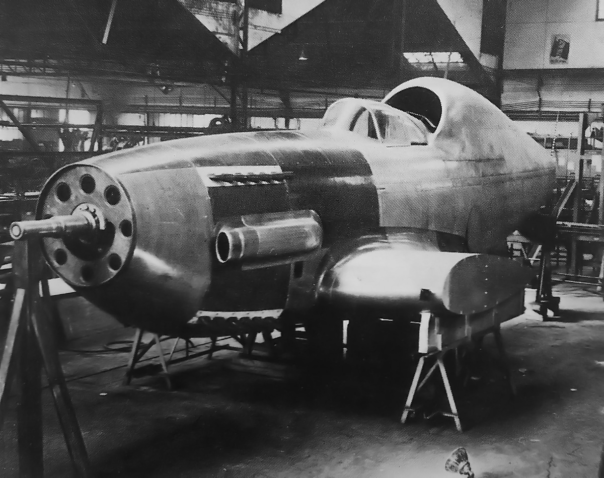
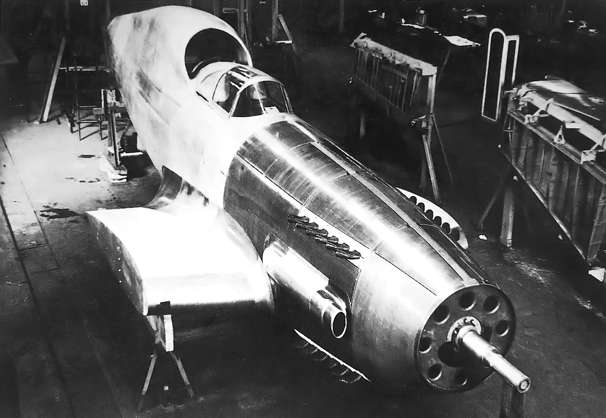
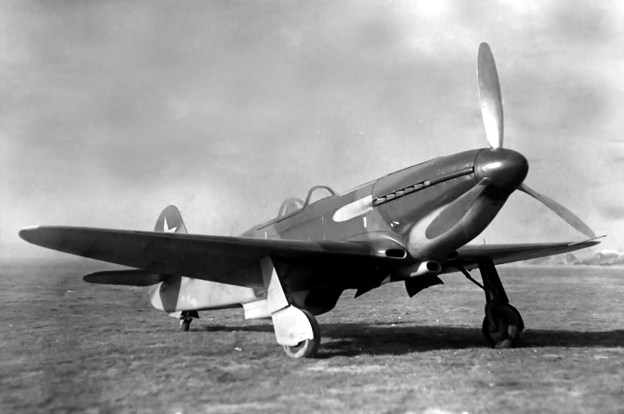
The Kawasaki Ki-64 looked very much like a continuation of the Ki-61 design, and while some of its features were inspired by other aircraft, the Ki-64 was an entirely independent design. The single-seat aircraft had a taildragger configuration and was of all-metal construction. Although designed as a fighter, the Ki-64 was primarily a research aircraft intended to test its unusual engine installation and evaporative cooling system. Proposed armament included one 20 mm cannon installed in each wing and two 12.7 mm machine guns or 20 mm cannons installed in the upper fuselage in front of the cockpit. The armament was never fitted to the prototype.

kawasaki-ki-64-engine-run

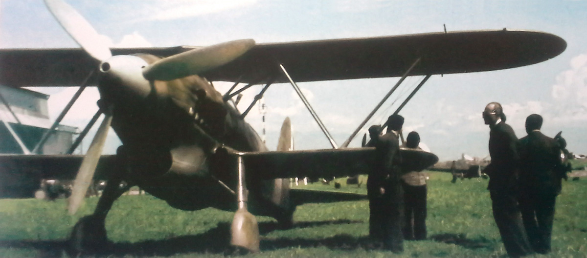
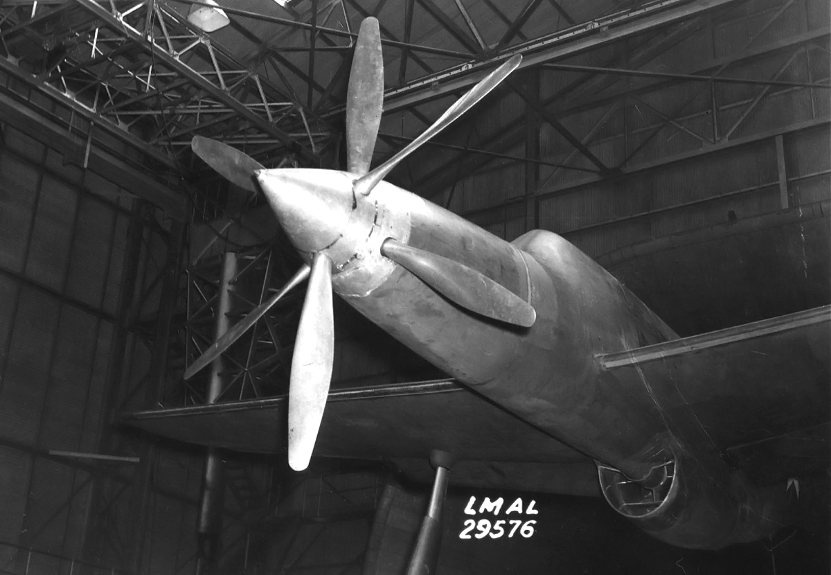
The Ki-64 appears to be preparing for an early test flight. The front engine’s intake scoop can be seen just above the exhaust stacks. Note the exhaust stains from the front engine and that the lightning bolt has not yet been painted on the fuselage.

The Ki-64 was powered by a Kawasaki Ha-201 (joint designation [Ha-72]11) engine that was comprised of two Kawasaki Ha-40 inverted V-12 engines coupled to a coaxial contra-rotating propeller. The Ha-40 (joint designation [Ha-60]22) was a licensed-built Daimler-Benz 601A engine and had a 5.91 in (150 mm) bore, a 6.30 in (160 mm) stroke, and a displacement of 2,070 cu in (33.9 L). As installed in the Ki-64, the shaft for the rear engine extended under the pilot’s seat and through the Vee of the front engine to the propeller gearbox. The rear engine drove the front adjustable-pitch propeller of the contra-rotating unit. The front engine drove the rear fixed-pitch propeller. Each set of propellers had three blades that were 9 ft 10 in (3.0 m) in diameter. The Ha-201 displaced a total of 4,141 cu in (67.9 L) and produced 2,350 hp (1,752 kW) at 2,500 rpm for takeoff and 2,200 hp (1,641 kW) at 2,400 rpm at 12,795 ft (3,900 m). Each engine section could operate independently of the other.

The engine sections had separate evaporative cooling systems. Heated water from the engine at 45 psia (3.1 bar) was pumped to a steam separator, where the water pressure dropped to 25 psia (1.7 bar), and about 2% of the water flashed to steam. The steam was then ducted at 16 psia (1.1 bar) through panels in the wings, where it was cooled and condensed back into water. The water then flowed back into the engine. The evaporative cooling system eliminated the drag of a radiator, and this enabled the aircraft to achieve higher speeds. It was believed that battle damage would not be much of a problem for the cooling system. The low pressure of the steam combined with steam’s low density meant that the amount of coolant lost through a puncture would be minimal, and the separate engines and cooling systems helped minimize the risk of a forced landing if damage did render one system ineffective.

The evaporative cooling system for the front engine was housed in the left wing, and the rear engine’s system was housed in the right wing. Each system consisted of two steam separators, an 18.5-gallon (70 L) tank in the wing’s leading edge near the fuselage, four upper and four lower wing condenser panels, an upper and lower condenser section in the outer flap, and a water tank in the fuselage. Sources disagree regarding the size of each fuselage tank, but combined, the tanks held around 52.8 gallons (200 L). Suspended below the right wing was a scoop that held oil coolers for the engines.

kawasaki-ki-64-ground

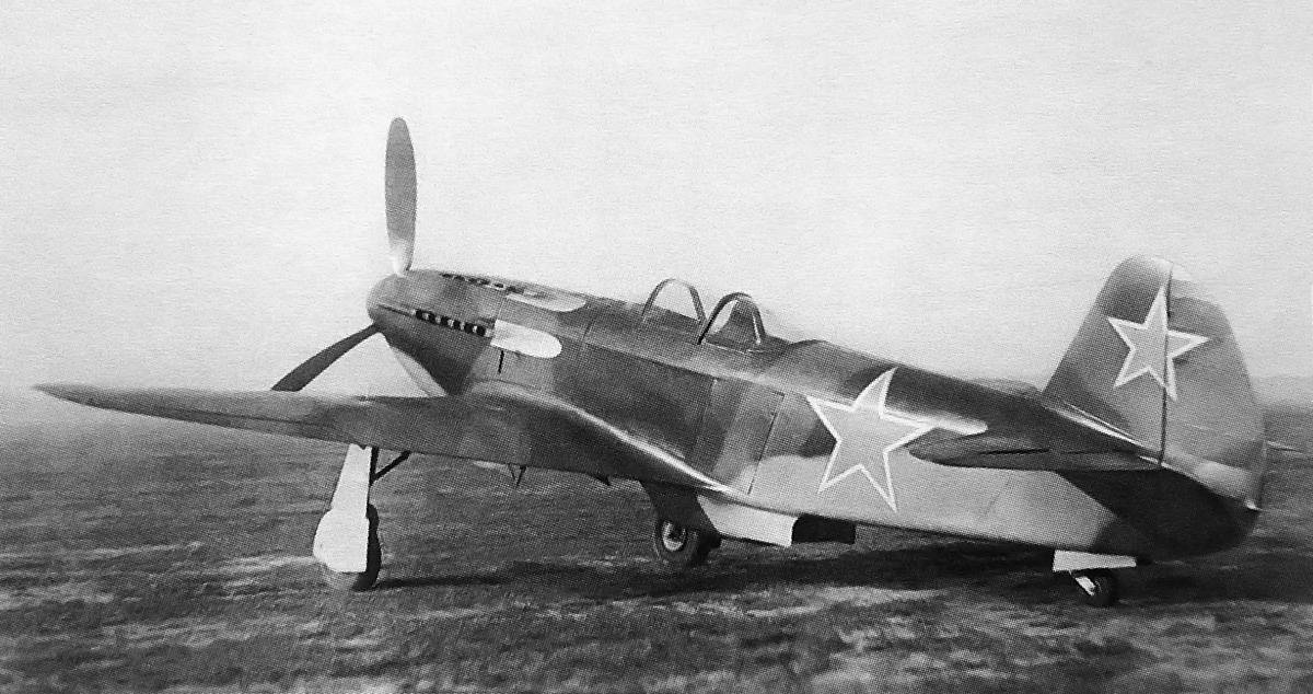
Another image of the Ki-64 doing a ground run. Note the aircraft’s resemblance to a Ki-61 Hien. Exhaust for the rear engine was collected in a manifold that exited the fuselage just above where the trailing edge of the wing joined the fuselage. That exhaust exit can just barely be discerned in this image.

The Ki-64 had a 44 ft 3 in (13.50 m) wingspan and was 26 ft 2 in (11.03 m) long. The aircraft had a top speed of 435 mph (700 km/h) at 13,123 ft (4,000 m) and 429 mph (690 km/h) at 16,404 ft (5,000 m). The Ki-64 could climb to 16,404 ft (5,000 m) in 5.5 minutes and had a service ceiling of 39,370 ft (12,000 m). Since the wings housed the cooling system, little room was left for fuel tanks. Each wing had a 22-gallon (85 L) fuel tank, and an 82-gallon (310 L) tank was housed in the fuselage; this gave the Ki-64 a 621 mile (1,000 km) range. The aircraft weighed 8,929 lb (4,050 kg) empty and 11,244 lb (5,100 kg) loaded.

While the Ki-64 was being built, a Ki-61 was modified to test the evaporative cooling system. With its radiator removed and evaporative panels added to its wings, the modified Ki-61 first flew in October 1942. Around 35 flights were made before the end of 1943, and they served to develop and refine the cooling system. The aircraft proved the validity of the evaporative cooling system and achieved a speed 25–30 mph (40–48 km/h) in excess of a standard Ki-61. However, the evaporative cooling system did require much more maintenance than a conventional system.

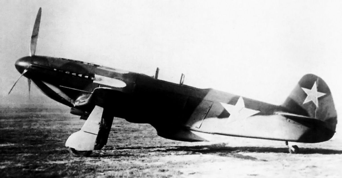
The Ki-64 was completed at Kawasaki’s plant at Gifu Air Field in November 1943. The aircraft underwent ground tests that revealed a number of issues. By December, the issues were resolved enough for flight testing to commence. The aircraft made four successful flights, but the rear engine caught fire on the fifth flight. The pilot was able to make an emergency landing at Kakamigahara, but the rear engine and parts of the rear fuselage and cooling system had been damaged. The Ha-201 engine was sent to Kawasaki’s engine plant in Akashi for overhaul, and the Ki-64 airframe was sent back to Gifu for repairs.

kawasaki-ki-64-in-flight

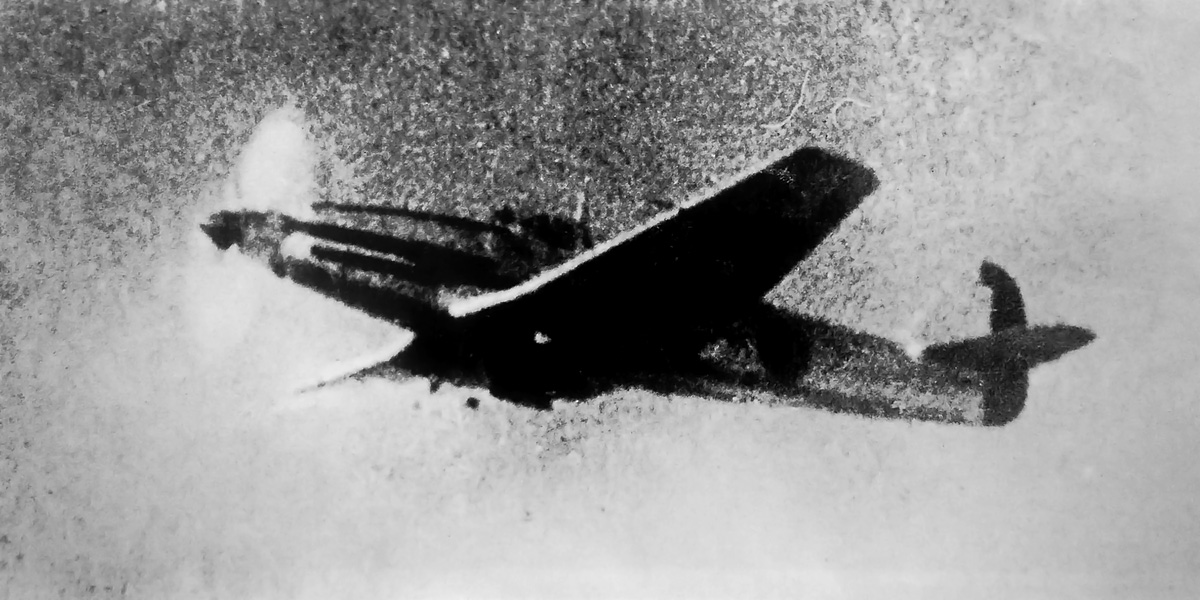
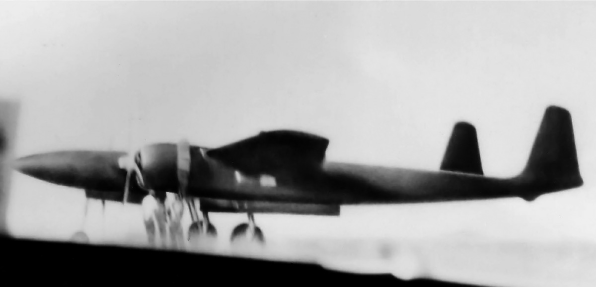
A poor image, but perhaps the only one, showing the Ki-64 in flight. The lightning bolt has been painted on the fuselage.

The short flying career of the Ki-64 had shown that its cooling system was insufficient. The system worked well for level flight, but it was inadequate for ground running, takeoff, and climb. When the system was overloaded, steam was not condensed back to water and was subsequently vented overboard via a 16 psi (1.1 bar) relief valve. The cooling system lost about 12 gallons (45 L) of water during a rapid climb from takeoff to 18,000 ft (5,500 m). Water freezing within the system, either while in flight or on the ground during cold temperatures, was another concern. Adding an alcohol mixture to the water coolant was a possible solution, but the Ki-64 never underwent any cold weather testing.

While undergoing repairs, the Ki-64 was to be modified and redesignated Ki-64 Kai. The existing propellers would be replaced with fully adjustable and feathering contra-rotating propellers, which would make it easier for one engine to be shut down in flight. The engines were to be replaced with more powerful Ha-140s (joint designation [Ha-60]41), each of which was capable of 1,500 hp (1,119kW). The coupled engine was designated Ha-321 (joint designation [Ha-72]21) and produced 2,800 hp (2,088 kW). With the changes, it was estimated that the Ki-64 Kai would have a top speed of 497 mph (800 km/h). However, the propeller and engines were delayed by more pressing war-time work, and the Ki-64 program was cancelled in mid-1944.

The Ki-64 airframe remained at Gifu where it was captured by American forces in 1945. Various parts of the cooling system were removed from the aircraft and shipped to Wright Field in Dayton, Ohio for further analysis and testing. The remainder of the Ki-64 was eventually scrapped.

kawasaki-ki-64-at-gifu

The K-64 as discovered by American forces at the end of World War II. The engines had been removed, and the aircraft was in a rather poor state. Note the canopy frame sitting on the wing.

Sources:
Japanese Army Fighters Part 1 by William Green and Gordon Swanborough (1977)
Japanese KI-64 Single Fighter with Two Engines in Tandem and Vapor-Phase Cooling, Air Technical Intelligence Review Report No. F-IR-100-RE by Petaja and Gilmore (31 July 1946)
Japanese Secret Projects by Edwin M. Dyer III (2009)
Japanese Aircraft of the Pacific War by René J. Francillon (1979/2000)
Encyclopedia of Japanese Aircraft 1900–1945 Vol. 4: Kawasaki by Tadashi Nozawa (1966)
The Xplanes of Imperial Japanese Army & Navy 1924–45 by Shigeru Nohara (1999)
Heinkel He 100 by Erwin Hood (2007)

fiat-cr42-db

FIAT CR.42 DB Fighter

By William Pearce

In late 1930s, FIAT developed the CR.42 Falco (Falcon), one of the last biplane fighter aircraft. The CR.42 was powered by an 840 hp (626 kW) FIAT A 74 RC38 radial engine. With good performance and excellent maneuverability, the CR.42 was one of the best biplane fighters ever built. However, frontline fighters had adopted new tactics in which speed controlled the fight, so the maneuverability of the biplane was traded for the speed of a monoplane. Looking to maximize a combination of speed and maneuverability, the Italian Air Ministry asked FIAT to re-engine the CR.42 with a 1,000 hp (746 kW) Daimler-Benz DB 601A engine. The resulting aircraft was designated CR.42 DB.

fiat-cr42-db

The FIAT CR.42 DB undergoing an engine run. Its Daimler-Benz DB 601 engine made the aircraft the fastest biplane ever built. However, its performance could not match contemporary monoplane fighters.

Some sources incorrectly list the DB 601-powered aircraft as the CR.42 B, which was a trainer built from a standard CR.42 by moving the engine forward, elongating the fuselage, and adding a second cockpit. Additionally, some sources claim the CR.42 DB’s engine was an Alfa Romeo RA 1000 RC41, which was a DB 601A built under license in Italy. However, the Alfa Romeo RA 1000 engine had not proceeded beyond initial testing by late 1941, after the CR.42 DB had already flown. It is unlikely that an untried RA 1000 test engine was installed in the CR.42 DB.

The FIAT CR.42 DB project was underway by early 1941. The aircraft was assigned serial number MM 469. In the span of a few weeks, a standard CR.42 was re-engined with the DB 601 power plant. Switching from a large, air-cooled, 14-cylnder radial engine to a long, liquid-cooled, V-12 engine necessitated many changes to the aircraft.

Like all CR.42s, the CR.42 DB consisted of a welded steel tube and alloy airframe. The fuselage was skinned in aluminum with the exception of the rear fuselage’s sides and bottom, which were covered with fabric. The wings and tail had a duralumin frame. The wings’ leading and trailing edges were aluminum, and fabric covered the rest of the surface. The horizontal and vertical stabilizers were aluminum-skinned. All control surfaces were had a duralumin frame and were covered in fabric.

FIAT CR42 DB right

The CR.42 DB with its lower wing removed. The removed bottom panel exposes some of the aircraft’s structure.

The entire front of the CR.42 DB was redesigned to accommodate the DB 601A engine and its radiator. The DB 601A was encased in a close-fitting, streamlined cowling. Positioned on the left side of the cowling was the engine’s air intake. Faired into the cowling’s upper deck were the blast tubes for the aircraft’s two 12.7 mm guns—each had 400 rounds of ammunition. A housing for the radiator was located under the engine. Scoops for oil coolers were placed in the wing roots of the lower wing (in the same location as a standard CR.42).

The CR.42 DB had the same 31.8 ft (9.70 m) upper and 21.3 ft (6.50m) lower wingspans as the standard CR.42, but those were the only specifications the two aircraft shared. The CR.42 DB was 1.8 ft (.54 m) longer at 28.9 ft (8.80 m). The aircraft was 507 lb (230 kg) heavier at an empty weight of 4,299 lb (1,950 kg). The CR.42 DB’s performance improved substantially over the standard CR.42. The CR.42 DB had a top speed of 323 mph (520 km/h) at 17,388 ft (5,300 m) and could climb to 16,404 ft (5,000 m) in 5:40. The aircraft had a ceiling of 34,777 ft (10,600 m) and a range of 715 mi (1,150 km). The standard CR.42 was 56 mph (90 km/h) slower, took an additional 1:40 to reach 16,404 ft (5,000 m), and had a 1,312 ft (400 m) lower ceiling.

FIAT CR42 DB color

This image shows the wing root scoop for the oil cooler and the induction scoop for the DB 601 engine. The CR.42 DB is shown at Caselle airfield in May 1941.

The CR.42 DB’s first flight was in March 1941, piloted by Commander Valentino Cus. The aircraft was delivered to the Centro Sperimentale (Experimental Center) at Guidonia Airfield (near Rome) for military tests in the summer of 1941. The CR.42 DB proved to be an exceptional aircraft; it was (and still is) the world’s fastest biplane. While not much slower than monoplane fighters then in service, the CR.42 DB’s speed could not be improved, whereas the speed of monoplane fighters would continue to increase as advancements were made.

Although an order for 150 aircraft was placed on 10 April 1941, series production was never started. The short supply of DB 601 engines available to Italy and the engine’s priority use in the more advanced Macchi MC.202 Folgore (Lightening) and Re.2001 Falco II (Falcon II) monoplane fighters left no DB 601s available for the CR.42 DB. Only one CR.42 DB was built. Some consideration was given to lengthening the CR.42 DB to 30.8 ft (9.38 m) and modifying it into a two-place training or reconnaissance aircraft. However, this project never proceeded beyond the initial design phase. Although the FIAT CR.42 DB was the pinnacle of biplane fighter performance, it was outclassed by frontline monoplane fighters as the era of biplane fighters came to an end.

FIAT CR42 P

The two-place, DB 601-powered CR.42. Some sources refer to the aircraft as the CR.42 R. However, the drawing appears to be labeled “R.42 P”. The “CR” stood for Caccia (Fighter) Rosatelli. Rosatelli was the aircraft’s designer, Celestino Rosatelli. Since the two-place aircraft was not a fighter, it makes sense that the “Caccia” designation would not be used.

Sources:
The FIAT Fighters 1930–1945 by Piero Vergnano (1969)
Italian Civil and Military Aircraft 1930–1945 by Jonathan W. Thompson (1963)
Aeronuatica Militare Museo Storico Catalogo Motori by Oscar Marchi (1980)
Tutti gli aerie del Re by Max Vinerba (2011)
– “Fantasmi di aerie e motori Fiat dal 1935 al 1945 (prime parte)” by Giovanni Masino Ali Antiche 106 (2011)
Fiat CR.42 Falco by Przemyslaw Skulski (2007)

Martin-Baker MB3 runup

Martin-Baker MB3 Fighter

By William Pearce

By 1939, it was clear that the British Air Ministry would not order the Martin-Baker MB2 into production. James Martin (main designer) and Captain Valentine H. Baker had already been at work designing a new fighter aircraft—the MB3. Since the MB2 had proved to be a well-designed fighter, the British Air Ministry ordered three prototypes of the MB3 fighter on 16 June 1939. The new aircraft would be built under Specification F.18/39, issued to Martin-Baker in May 1939. The minimum requirements of Specification F.18/39 were a speed of 400 mph (644 km/h) at 15,000 ft (4,572 m), a ceiling of 35,000 ft (10,668 m), an endurance of 2.5 hours, and an armament of four 20 mm cannons. With the contract issued, Martin worked to finalize the MB3’s design.

Martin-Baker MB3 Denham guns

The nearly complete Martin-Baker MB3 in the summer of 1942 at Martin-Baker’s factory in Denham. The aircraft is not painted, and its six 20 mm cannons are installed. The cannons were removed before flight testing.

The timetable for completing the aircraft was rather optimistic for the relatively small Martin-Baker company. The original contract stated the first MB3 prototype was to be ready by 15 December 1939, with the two remaining aircraft completed by 15 February 1940. At this early stage, the aircraft was to be powered by a Rolls-Royce Griffon engine. By September 1939, it was apparent that the Griffon engine would not be available to Martin-Baker for some time. At the insistence of the Air Ministry, the Napier Sabre replaced the Griffon, and the entire aircraft was redesigned for the new engine. This resulted in a new contract that was somewhat delayed but ultimately signed on 11 August 1940. Britain was now fully involved in World War II, and Martin-Baker was inundated with other work of a higher priority. Therefore, completing the first MB3 took longer than anticipated. By the end of 1941, Martin-Baker was informed that there would be no production orders for the MB3, but the first prototype was so far along that it made sense to finish it.

Construction of the Martin-Baker MB3 followed the established company practice of using a tubular steel frame to make up the fuselage structure. The main wing spar was made of laminated steel, with the number of laminations decreasing near the wingtips. The rest of the wing structure formed a torsion box of extreme rigidity. The entire aircraft was covered with stressed aluminum skin, but many panels could be opened or removed for quick access to equipment and armament. The rudder was fabric-covered, but the rest of the control surfaces were skinned with aluminum.

Martin-Baker MB3 left

The MB3 during its brief flight testing career at RAF Wing. Note the retractable stirrup and fold-down door for cockpit entry.

The aircraft used pneumatically controlled split flaps and had spring loaded aileron gap seals to increase its roll rate and improve aerodynamics. The elevator also had gap seals. Fuel was carried in a fuselage tank in front of the cockpit. The aircraft’s fully retractable main landing gear had a wide track of 15 ft 5 in (4.7 m). The tailwheel retracted into an open well under the tail. The landing gear was lowered by gravity and raised by a pneumatic system, which was separate from the system that controlled the flaps.

Each wing housed three 20 mm cannons with 200 rpg, all installed outside of the aircraft’s main gear. The ammunition belts were installed parallel to the cannons; each bullet had to turn 90 degrees before being fed into the breach. This “flat-feed” ammunition system was patented by Martin. The cannon and ammunition arrangement made for a compact package that could be easily accessed and quickly serviced. With its six 20 mm cannons, the MB3 was one of the most heavily armed fighters of World War II.

Martin-Baker MB3 runup

This image of the MB3 running up gives a good view of the aircraft’s wide-track landing gear and the close-fitting cowling that covered the Sabre engine. Also visible are the under-wing scoops for the radiator and oil cooler.

The Rolls-Royce Vulture X-24 engine was also considered to power the MB3. The V-12 Griffon was initially selected because it was a far less complex power plant than the Vulture or Sabre. However, because the Sabre was more readily available than the Griffon and was favored by the Air Ministry, it was ultimately selected to power the MB3. The 2,020 hp (1,506 kW) Sabre II engine had 24 cylinders arranged in a horizontal H configuration and used sleeve valves. The engine drove a three-blade de Havilland propeller that was 14 ft (4.27 m) in diameter. Engine cooling was provided by a radiator installed in the right wing and an oil cooler installed in the left wing. The radiator ran from the wing root to the main gear, and the oil cooler was about half the size of the radiator. The scoops for the radiator and oil cooler extended about 5 in (127 mm) under the wings and were positioned between the gear wells and the flaps.

The MB3 had a 35 ft (10.7 m) wingspan and was 35 ft 4 in (10.8 m) long. The aircraft had a gross weight of 11,497 lb (5,215 kg). The MB3 had a top speed of 418 mph (673 km/h) at 20,000 ft (6,096 m). However, Martin claimed that Captain Baker had achieved 430 mph (632 km/h) at the same altitude, albeit without the drag that the six cannons would produce. At sea level, the aircraft was capable of 372 mph (599 km/h), and maximum cruising speed was 370 mph (595 km/h) at 15,000 ft (4,572 m). The MB3’s landing speed was 88 mph (142 km/h). The aircraft had a service ceiling of 35,000 ft (10,668 m) and a range of approximately 420 miles (676 km).

Martin-Baker MB3 rear

This rear view of the MB3 illustrates the aircraft’s fine fit and finish. The aileron and elevator gap seals can just be seen.

The first MB3 was given the serial number R2492. The aircraft was expected in March 1942 but was not completed until early August. The aircraft was trucked to Royal Air Force Station Wing (RAF Wing) in Buckinghamshire for flight testing. Surrounded by small fields and many trees, the small airbase of RAF Wing was not an ideal location for flight testing. Martin had objected to using RAF Wing, but the Air Ministry insisted.

Captain Baker was at the controls when the MB3 flew for the first time on 31 August 1942. The six wing cannons had been installed when the aircraft was built at Denham (near London) but were removed before the aircraft flew and were never reinstalled. Ballast had been added to simulate the weight of the cannons and their ammunition. Flight testing revealed that the aircraft had excellent maneuverability and handling characteristics. However, difficulty was experienced with the Sabre engine, and engine overheating issues troubled the MB3.

Martin-Baker MB3 right rear

Many sources claimed that the MB3 was fitted with a bubble canopy after its first flight. This belief stems from a doctored image of the MB3 with a bubble canopy meant to illustrate what the production version of the aircraft would look like. A bubble canopy was never installed on the MB3.

On 12 September 1942, the aircraft made its 10th flight. Captain Baker had just taken off when the engine seized, a result of a sleeve drive crank failure. Low to the ground and without any options, Captain Baker put the MB3 down in one of the many small fields lined with hedgerows and other obstacles surrounding RAF Wing. The aircraft clipped a pile of straw and crashed through a hedgerow at high speed. The MB3 cartwheeled, broke apart, and caught fire. Captain Baker was killed instantly.

The death of Captain Baker was a bitter blow for the Martin-Baker company. Martin took it especially hard; he had lost his friend in an aircraft powered by an engine he did not want to use and at a test site that he thought was inadequate. It was not long before Martin and the Martin-Baker company began work to improve aircrew safety and developed a series of ejection seats, which the company still manufactures today.

Martin-Baker MB3 with Captain V H Baker

Captain Valentine H. Baker poses with the MB3 shortly before a test flight. The engine seized on the MB3’s 10th flight, and Captain Baker was killed during the subsequent crash landing.

With the first MB3 prototype destroyed, Martin’s attention turned to the partially completed second prototype (R2496). Construction of the third prototype (R2499, or possibly R2500) was probably never started. Martin had already designed the MB3A, which was the production version of the MB3. The MB3A had a bubble canopy (that was never fitted to the prototype), and its cockpit was moved slightly forward to improve the pilot’s view over the wing. The MB4 had also been designed; it used a Bristol Centaurs engine in the same basic MB3 airframe. However, since the Air Ministry was finally willing to provide Martin-Baker with a Griffon engine and with the MB3’s performance now on par with existing aircraft, Martin sought to redesign the entire aircraft as the improved MB5 fighter. The Air Ministry was agreeable, and serial R2496 was reallocated to the MB5 aircraft in late 1943. The MB5 flew in 1944 and was another outstanding aircraft. However, the MB5 never went into production, and it was the last aircraft built by Martin-Baker.

Sources:
– “Martin-Baker Fighters,” by Bill Gunston, Wings of Fame Volume 9 (1997)
British Experimental Combat Aircraft of World War II by Tony Buttler (2012)
RAF Fighters Part 2 by William Green and Gordon Swanborough (1979)
The British Fighter since 1912 by Francis K. Mason (1992)
Interceptor Fighters of the Royal Air Force 1935–45 by Michael J. F. Bowyer (1984)
https://picasaweb.google.com/109207897425941419378/MartinBakerAircraft

Republic XP-69 side

Republic XP-69 Fighter

By William Pearce

In February 1940, the United States Army Air Corps (AAC) issued Request for Data R40-C to various engine and aircraft manufacturers. R40-C encouraged aircraft manufacturers to propose unorthodox aircraft capable of at least 450 mph (724 km/h), but preferably 525 mph (845 km/h), and to meet other requirements outlined in Type Specification XC-622. R40-C also asked aircraft engine manufacturers to develop new power plants. Initially, a total of 26 aircraft designs were submitted by six selected aircraft companies and included a mix of eight different engines from four engine companies. Republic Aviation’s entry carried the company designation AP-12.

Republic AP-12 Rocket

The AP-12 Rocket was Republic’s entry into the R40-C fighter competition. Note the mid-fuselage-mounted Wright R-2160 Tornado engine.

Like almost all of the other R40-C entries, the Republic AP-12 ‘Rocket’ was not a conventional aircraft. The AP-12 had a streamlined, cigar-shaped fuselage and utilized a tricycle undercarriage. The aircraft’s Wright R-2160 Tornado engine was placed behind the pilot. The engine’s extension shaft ran under the cockpit and drove a six-blade, contra-rotating airscrew at the front of the aircraft. Four machine guns were installed in the AP-12’s nose and fired through the propellers, and an additional machine gun was installed in each wing, outside of the propeller arc. A 20 mm cannon was installed in the nose of the aircraft and fired through the propeller hub.

After the AP-12 placed 13th out of the R40-C entries, Republic literally went back to the drawing board and created a new design, designated AP-18. The AP-18 possessed some of the same lines and used the same engine as the AP-12; however, the R-2160 engine was now installed in the nose of the aircraft. Republic submitted its AP-18 design to the AAC in July 1941 and was awarded a contract in December 1941 to produce two prototypes of the aircraft, designated XP-69 (it also carried the “Materiel, Experimental” project designation MX-162).

Republic XP-69 15-Sept-1941 inboard drawing

This XP-69 drawing dated 15 September 1941 clearly shows the Wright Tornado installed in the nose of the aircraft, with the turbosupercharger and its ancillary equipment mounted behind the cockpit. While the leading edge is distorted, the trailing edge shows the inner wing section perpendicular to the fuselage, then tapering toward the wing tip. This drawing was discovered in the National Archives by Kimble McCutcheon of the Aircraft Engine Historical Society.

The Republic XP-69 was an all-metal, high-altitude interceptor fighter with a conventional layout. The aircraft was powered by a 42-cylinder R-2160 engine that produced 2,500 hp (1,864 kW) at 4,600 rpm and was installed in a normal manner, without an extension shaft. The engine drove a 13 ft 8 in (4.17 m) diameter, six-blade, contra-rotating propeller built by Hamilton Standard. The turbosupercharger, intercoolers, radiator, and oil coolers were all positioned behind the cockpit. The scoop mounted under the cockpit brought in air for the radiator, oil coolers, intercoolers, and turbosupercharger via a complex series of ducts. The scoop also incorporated a boundary layer air bleed duct. Initially, four air exit doors were located under the fuselage, but the exits were later relocated, with two on each side of the XP-69 (the oil cooler was the lower exit and the intercooler the upper). However, radiator and boundary layer air as well as exhaust from the turbosupercharger exited from the bottom of the aircraft.

Most sources contend that the R-2160 engine was installed behind the XP-69’s cockpit. However, all of the equipment and associated ducting that was installed behind the cockpit left no room for anything else. In addition, a drawing dated 15 September 1941 found in the U.S. National Archives by Kimble McCutcheon clearly shows the Wright Tornado installed in the nose of the aircraft.

Republic XP-69 side

The Republic XP-69 model undergoing wind tunnel tests. Note the revised belly scoop and the air exits on the rear fuselage. The man pictured at the bottom of the photo gives some scale to the large size of the model, which was 3/4-scale. (image via Langley Memorial Aeronautical Laboratory / NASA)

The XP-69 utilized a pressurized cockpit in a fairly narrow fuselage, and its standard taildragger landing gear was fully retractable. The aircraft’s armament consisted of two .50 cal machine guns and one 37 mm cannon installed in each wing, outboard of the main landing gear. The machine guns had 320 rpg, and the cannons had 40 rpg. Some sources state an alternative armament installation consisted of six .50 cal machine guns in the wings and no cannons. Initially, the leading and trailing edges of the inboard wing sections were exactly perpendicular to the fuselage. This was later revised so that the wing’s taper was unchanged throughout its leading and trailing edges. Slotted flaps extended across about 50 percent of the wing’s trailing edge to help lower the heavy aircraft’s landing speed.

The XP-69 was a large aircraft with a wingspan of 52 ft (15.85 m), a length of 51 ft 8 in (15.75 m), and a height of 17 ft 3 in (5.26 m). The aircraft had a top speed of 450 mph (724 km/h) at 35,000 ft (10,668 m), an initial climb rate of 2,750 fpm (13.97 m/s), and a ceiling of 48,900 ft (14,905 m). Eight wing fuel tanks provided a total capacity of 386 gal (1,461 L), and a 114 gal (432 L) fuselage tank brought the aircraft’s total fuel capacity to 500 gal (1,893 L), which provided a maximum range of 1,800 miles (2,897 km). Wind tunnel tests were conducted with a 75 gal (284 L) drop tank under each wing of the aircraft. The XP-69 had an empty weight of 15,595 lb (7,074 kg), a gross weight of 18,655 lb (8,462 kg), and a maximum weight of 26,164 lb (11,868 kg).

Republic XP-69 top

Top view of the XP-69 model illustrates the aircraft’s relatively narrow fuselage and that its wings had a continuous taper. Note the 75 gallon drop tank mockups on the left of the image and the Douglas XB-19 model on the right. (image via Langley Memorial Aeronautical Laboratory / NASA)

A 1/20-scale XP-69 model was used for spin recovery tests, the results of which were generally satisfactory—although, recovery was problematic at 30,000 ft (9,144 m). A 3/4-scale model of the XP-69 was completed around June 1942 and began wind tunnel tests in August. The extensive tests were to analyze and evaluate the aircraft’s stability, controls, and cooling system and included fitting the model with 10 ft (3.0 m) diameter, contra-rotating propellers driven by two 25 hp (19 kW) electric motors in the fuselage. The tests indicated some longitudinal instability; the forecasted rate of roll was inadequate, and the estimated control forces for full aileron deflection were excessive. The XP-69 would utilize a control yoke, which would provide a certain degree of mechanical advantage over a control stick. Tests also revealed that the cooling system was not as efficient as expected and required some revision.

Construction of the first prototype began in November 1942 and incorporated changes shown necessary from the various wind tunnel experiments. While development of the XP-69 continued, the R-2160 engine was delayed with design issues that, in turn, would delay the aircraft. Also, a miscommunication had occurred: Republic thought the first engines would be capable of 2,500 hp (1,864 kW) at 4,600 rpm. In reality, the R-2160 would produce only 2,350 hp (1,752 kW) at 4,150 rpm; 2,500 hp (1,864 kW) was the engine’s developmental goal. The reduced power would inhibit the XP-69’s performance, and its 450 (724 km/h) mph top speed was already seen as optimistic.

Republic XP-69 flaps

The XP-69 model with its flaps fully deployed at 40 degrees. The slotted flaps extended aft and down. Note the air exits on the side of the fuselage. (image via Langley Memorial Aeronautical Laboratory / NASA)

Republic wanted to end work on the XP-69 and focus their resources on an alternative project. The company believed their AP-19 design (in a way, a Pratt & Whitney R-4360-powered P-47) held more potential and could fly sooner than the XP-69. The AP-19 (designated XP-72) was designed for and proposed to the AAC at the same time as the AP-18/XP-69. Since the AAC wanted an R-2160-powered fighter as soon as possible, Republic’s AP-18/XP-69 design was contracted, as it was the most appealing candidate. But now, with the engine issues affecting the XP-69, the XP-72 could no longer be overlooked as the superior aircraft. The XP-69 was cancelled on 11 May 1943, and two prototypes of Republic’s XP-72 were ordered on 18 June 1943. The Wright R-2160 Tornado was cancelled on 12 February 1944.

Note: Most sources list the XP-69’s wingspan as 51 ft 8 in (15.75 m) and its length as 51 ft 6 in (15.70 m). The dimensions given in this article, a 52 ft (15.85 m) wingspan and a 51 ft 8 in (15.75 m) length, come from two NACA reports from the 1940s.

Republic XP-69 nose

This image of the XP-69’s nose displays the propellers that were powered by two 25 hp motors for the wind tunnel tests. Also note the complex segmentation of the belly scoop inlet. (image via Langley Memorial Aeronautical Laboratory / NASA)

Sources:
Tornado: Wright Aero’s Last Liquid-Cooled Piston Engine by Kimble D. McCutcheon (2001)
U.S. Experimental & Prototype Aircraft Projects: Fighters by Bill Norton (2008)
American Secret Projects 1937–1945 by Tony Buttler and Alan Griffith (2015)
American Secret Pusher Fighters of World War II by Gerald H. Balzer (2008)
Stability and Control Tests of a 3/4-Scale Model of the XP-69 Airplane in the NACA Full-Scale Tunnel by Harold H. Sweberg (7 January 1943)
Compilation of Test Data on 111 Free-Spinning Airplane Models Tested in the Langley 15-Foot and 20-Foot Free-Spinning Tunnels by Malvestuto, Gale, and Wood (1947)
http://www.weakforcepress.com/tornado_errata.shtml
http://www.weakforcepress.com/XP-69/index.html
http://crgis.ndc.nasa.gov/historic/Test_139:_XP-69_3/4%E2%80%93scale_Model_%28Stability_and_Cooling%29

CAC CA-14A front

Commonwealth Aircraft Corporation CA-14/A Fighter

By William Pearce

In late 1941, the Australian aviation industry took stock of its resources and worked to create an indigenous fighter aircraft to defend against the Japanese. The result of this effort was the Commonwealth Aircraft Corporation (CAC) CA-12, CA-13, and CA-19 Boomerang fighters. In many respects, the Boomerang was an outgrowth of the CAC Wirraway general use aircraft. The Wirraway itself was a modified, licensed production version of the North American NA-16 (also referred to as NA-33) trainer. With a low top speed and poor altitude performance, the very maneuverable and rugged Boomerang found itself excelling in the ground attack role. In late 1942, The Australian War Cabinet and CAC sought to improve the Boomerang’s altitude performance by adding a turbosupercharger. This new aircraft was designated CA-14.

CAC CA-14 front

At first glance, the CAC CA-14 looks like a standard Boomerang fighter, but the aircraft’s unique turbosupercharger scoop can be seen on the side of the fuselage. Less noticeable modifications from a standard Boomerang include a new wing root fairing and a slightly enlarged tail.

The CA-14 was a standard CA-13 Boomerang that had been heavily modified to accommodate a turbosupercharger. Like all CA-13 Boomerangs, the CA-14 had a 1,200 hp (895 kW) Pratt & Whitney (P&W) R-1830 engine. The fuselage was built with a steel tube frame, and the wings and tail were built up from aluminum components. The wings housed four .303 machine guns and two 20 mm cannons. The tail, cowling, lower part of the fuselage, and in front of the cockpit were skinned with aluminum. All tail control surfaces were fabric-covered, and the ailerons were aluminum-skinned.

Unlike a normal Boomerang, the CA-14 had a new cowling that omitted the air intake scoop positioned above the engine on a standard Boomerang. A large scoop was added on the left side of the fuselage, next to the cockpit, and provided intake air for the engine and air for the turbosupercharger’s intercooler. Air exited the intercooler via an adjustable flap located on the right side of the upper fuselage, just behind the cockpit. The engine’s exhaust pipe was extended back along the right side of the fuselage to the turbosupercharger installed behind the cockpit. The General Electric (GE) B-2 turbosupercharger was from a Consolidated B-24 Liberator, and the Harrison intercooler was from a Boeing B-17 Flying Fortress; these parts were chosen because they were available, not because they were ideal. The fuselage was skinned with aluminum to just behind the turbosupercharger. Farther aft, the fuselage was wood-covered. A new, more streamlined fairing was installed on the wing’s leading edge. The fairing ran from the wing root to the fuselage, over the main gear wheel bays. The CA-14’s vertical stabilizer was slightly enlarged, and it used an 11 ft (3.35 m), three-blade, Curtiss propeller.

CAC CA-14 left side

The CA-14’s large scoop can be seen in this view. The scoop created turbulence that interfered with the aircraft’s tail. Pilot visibility was improved over the standard Boomerang by removing the engine intake scoop on the upper cowling.

The CA-14 was assigned serial number A46-1001 and first flew on 13 January 1943 piloted by Flt. Lt. John Holden. Its performance was on par with a standard Boomerang below 10,000 ft (3,048 m) but was superior above that altitude. At 28,000 ft (8,534 m), the CA-14 had a top speed of 354 mph (570 km/h) and a 1,400 fpm (7.1 m/s) rate of climb, while the standard Boomerang was 76 mph (122 km/h) slower at 278 mph (447 km/h) and could only climb at 450 fpm (2.3 m/s). The CA-14 had a 2,150 fpm (10.9 m/s) initial rate of climb and a ceiling of 36,000 ft (10,973 m), which was 2,000 ft (610 m) higher than a standard Boomerang’s ceiling. The CA-14 had the same 36 ft (10.97 m) wingspan and 25.5 ft (7.77 m) length as the Boomerang; however, it was some 400 lb (180 kg) heavier, at 8,095 lb (3,672 kg). The aircraft had a range of 930 miles (1,497 km).

Flight testing revealed directional instability and cooling issues with engine and turbosupercharger. The large scoop mounted on the side of the fuselage created turbulent air which interfered with the aircraft’s tail and caused some instability and buffeting. Starting in May 1943, the CA-14 was reworked to solve its issues and was redesignated CA-14A. Changes included adding a new, larger vertical stabilizer with an aluminum-skinned rudder and deleting the scoop from the aircraft’s fuselage. The engine cowling was reworked to provide better cooling, and a geared (3 to 1), 10-blade cooling fan was added behind the spinner. Air for the engine and intercooler was taken from the high-pressure area behind the cooling fan and internally ducted in the left side of the fuselage back to the turbosupercharger. A GE B-13 turbosupercharger and an AiResearch intercooler replaced the original units. The CA-14A was fitted with a three-blade Hamilton Standard or de Havilland propeller (sources disagree on which, but perhaps both propellers were tested), and its guns were removed. First flown around 26 July 1943, the CA-14A most likely achieved better performance than the CA-14; however, specifics have not been found. Sources indicate the CA-14A’s ceiling was in excess of 40,000 ft (12,192 m).

CAC CA-14 and CA-14A

A comparison of the CA-14 (top) and CA-14A (bottom), with its revised tail and cowling. The exit flap for the intercooler can bee seen in the upper fuselage, just behind the cockpit. The installation of the supercharger and its required accessories in the Boomerang’s small airframe was an impressive feat of engineering.

The ultimate goal of improving the Boomerang was to install a 1,450 hp (1,081 kW) P&W R-2000 engine and GE B-9 turbosupercharger in the aircraft. Originally, these changes were to be incorporated when the aircraft was rebuilt as the CA-14A. However, the United States was very reluctant to provide a license for supercharger production, and CAC’s production of licensed R-2000 engines encountered technical setbacks. The estimated speed of an R-2000-powered Boomerang was 286 mph (460 km/h) at sea level and 372 mph (599 km/h) at 27,000 ft (8,230 m). The aircraft’s rate of climb at sea level was 2,100 fpm (10.7 m/s) and 1,770 fpm (9.0 m/s) at 30,000 ft (9,144 m).

Based on the known performance of the CA-14 and the estimated performance of the R-2000-powered Boomerang, the Minister for Aircraft Production recommended that 120 R-2000-powered fighters be ordered. However, the Australian War Cabinet approved only 50 aircraft. With such a short production run, it was not worth the inevitable delays and required resources to upgrade Boomerang production to a new standard, especially with better performing fighters from the United States and Britain already arriving in Australia. As a result, the 50 aircraft were completed as CA-19 Boomerangs, which differed little from the CA-13s and CA-12s.

CAC CA-14A front

This view of the CA-14A displays its 10-blade engine cooling fan as well as its lack of armament. Undoubtedly, the aircraft’s performance was much improved, but its usefulness was in question since superior British and American aircraft were available in Australia. Note the Republic P-47 Thunderbolts in the background.

While the A46-1001 airframe was being designed and tested with its turbosupercharger, CAC looked to take the next step to enhance performance by fitting a 1,700 hp (1,268 kW) Wright R-2600 engine to an even more modified Boomerang. However, the availability of R-2600 engines to Australia was in question, and modifications to the Boomerang airframe would be substantial. It was deemed more practical to start development of a new aircraft with a 2,000 hp (1,491 kW) P&W R-2800 engine. Designated CA-15, this new aircraft would eventually fly, but with a Rolls-Royce Griffon V-12 engine and little resemblance to its initial design heritage.

The obsolete CA-14A continued to undergo flight testing and was used for high altitude weather observations, regularly flying at 40,000 ft (12,192 m). It was removed from service in 1946 and scrapped in 1947 (some sources say March 1949).

Note: The B-13 turbosupercharger was interchangeable with the B-2. Several sources state that CAC intended to install a B-9 turbosupercharger in the CA-14/A aircraft, but no GE references to a B-9 turbosupercharger have been found. Perhaps “B-9” was a typo or was a designation given to a licensed production or export model (like “B-10” for turbosuperchargers supplied to Britain).

CAC CA-14A left side

For the CA-14A, the large fuselage scoop was removed, and air to the turbosupercharger was delivered via an internal duct. The location of that duct can be discerned by the bulge running along the side of the fuselage

Sources:
Wirraway, Boomerang & CA-15 in Australian Service by Stewart Wilson (1991)
Wirraway to Hornet by Brian L Hill (1998)
Australia’s Lost Fighter: The CA-15 and its Demise by David Clark (2010)
http://www.australianflying.com.au/news/warbirds-the-turbo-interceptor-boomerang

Sud-Est SE 580 cowling

Sud-Est (SNCASE) SE 580 Fighter

By William Pearce

The state-owned French aircraft manufacturer SNCAM (Société nationale des constructions aéronautiques du Midi or National Society of Aircraft Constructors South) was formed in March 1937 when the Dewoitine firm was nationalized. Many Dewoitine personnel, including the company’s founder, Émile Dewoitine, continued to work for SNCAM. As a result, aircraft designed and built at SNCAM continued to bear the Dewoitine name.

Sud-Est SE 580 model

Wind tunnel model of the Sud-Est SE 580 complete with contra-rotating propellers.

In 1940, SNCAM began studies of a new fighter aircraft. The aircraft was based on a continuing design evolution that started with the Dewoitine D.520 production fighter and progressed through the D.551/552 pre-production fighters. SNCAM’s new fighter design was designated M 580.

The M 580 aircraft was a tractor design with conventional undercarriage. However, the power plant was unusual in that it utilized two Hispano-Suiza 12Z engines coupled in tandem and driving a coaxial contra-rotating propeller (similar to the Arsenal VB 10). The M 580 was designed by Robert Castello and Jacques Henrat, who had been very involved with previous Dewoitine fighter designs. Before much design work was completed, SNCAM was absorbed into SNCASE (Société nationale des constructions aéronautiques du Sud-Est or National Society of Aircraft Constructors Southeast) in late 1940.

With the SNCASE (often referred to as Sud-Est) takeover and the German occupation of France, the M 580 design languished during the war. Under Sud-Est, the aircraft was redesignated SE 580. Wind-tunnel tests were conducted in 1943, and the SE 580 design was changed to incorporate a new engine then under development. Gone was the tandem V-12 engine configuration, and in its place was a single 24-cylinder Hispano-Suiza 24Z engine. With much of France liberated in 1944, two SE 580 prototypes were ordered by the Ministère de l’Air (French Air Ministry). The Marine Nationale (French Navy) was interested in a navalized version designated SE 582 and ordered two prototypes in early 1945.

Sud-Est SE 580 HS 24Z

The SE 580 with open cowling revealing the 24-cylinder, 3,600 hp (2,685 kW) Hispano-Suiza 24Z engine.

Work on the SE 580 prototype was started first. The aircraft was of all-metal construction with fabric-covered control surfaces. The aircraft’s structure, especially the wings, followed basic Dewoitine design principals used in their earlier fighter aircraft. The SE 580 featured dive recovery flaps positioned under the wing and outside of the fully retractable main landing gear. Another unusual feature was that the incidence of the aircraft’s horizontal stabilizer was adjustable.

The smooth flow of the aircraft’s fuselage was interrupted by a large hump behind the cockpit. This structure housed the scoop that directed air through a radiator positioned horizontally in the aircraft’s rear fuselage. Cooling air entered a large opening just behind the cockpit, traveled down through the radiator, and exited the fuselage via a ventral flap. The intake also incorporated a slot for boundary layer air bleed. The radiator’s location in the center of the aircraft offered some inherent protection that was further enhanced by rear armor plating to protect against enemy fire.

Three fuselage fuel tanks and one fuel tank in each wing held a total of 660 gallons (2,500 L). A drop tank under the fuselage held an additional 79 gallons (300 L) of fuel. The SE 580’s Hispano-Suiza 24Z engine was an H-24 that was forecasted to produce 3,600 hp (2,685 kW). The 24Z would turn an 11.5 ft (3.50 m) diameter, six-blade, contra-rotating propeller.

Sud-Est SE 580 front

The supercharger intakes and numerous exhaust stacks interrupt the otherwise clean lines of the SE 580’s fuselage. The dorsal radiator scoop created a large blind spot for the pilot. One must wonder how cleanly air would flow into the scoop after being disrupted by the canopy.

The SE 580’s armament was quite substantial and consisted of a 30 mm cannon mounted between the engine’s upper cylinder banks and firing through the propeller hub. Each wing housed two 20 mm cannons and four 7.5 mm (or three 12.7 mm) machine guns. A hardpoint under each wing could accommodate a 1,102 lb (500 kg) bomb. A photo reconnaissance version would accommodate a vertical camera in the central fuselage.

The SE 580 had a 52.0 ft (15.86 m) wingspan and was 42.7 ft (13.0 m) long. The aircraft had an empty weight of 11,228 lb (5,093 kg) and a gross weight of 17,919 lb (8,128 kg). The SE 580 had a top speed of 373 mph (600 km/h) at sea level and 465 mph (749 km/h) at 30,512 ft (9,300 m). Its landing speed was 88 mph (141 km/h). The SE 580 could climb to 19,685 ft (6,000 m) in just over six minutes and had a theoretical ceiling of 44,619 ft (13,600 m). The aircraft’s maximum range was 1,709 miles (2,750 km).

By 1946, construction of the first SE 580 prototype was well underway, and a Hispano-Suiza 24Z engine was installed in the airframe. Unfortunately, problems with the 24Z engine resulted in its cancellation. The Arsenal 24H was selected as the replacement engine. The 4,000 hp (2,983 kW) 24H was also a 24-cylinder engine in an “H” configuration but had many differences when compared to the 24Z. The 24H was heavier and had a different propeller location; it used a single rotation, 12.1 ft (3.70 m) diameter, five-blade propeller. These differences required numerous, complex changes to the SE 580. The longer propeller was located 5.12 in (130 mm) lower on the engine and required changes to the aircraft’s landing gear and wings to maintain acceptable ground clearance. Wind-tunnel tests indicated further wing changes would be needed and that the engine had to be moved forward. In light of all the required changes, budgetary cutbacks, Sud-Est’s preoccupation with other projects, and the emergence of jet aircraft, the SE 580 was cancelled in 1947.

Sud-Est 580 rear

This rear view of the SE 580 shows the large radiator housing behind the cockpit. Note the cooling air exit flap under the fuselage.

SE 582 development trailed behind that of the SE 580; the French Navy was more interested in the Sud-Ost SO.8000, and Sud-Est was more focused on the SE 580. Changes needed to navalize the aircraft included incorporating an arrestor hook and folding wings. Construction of the SE 582 was limited to components that were shared with the SE 580, but it does not appear that any substantial part of the SE 582 was ever completed. The SE 582 had the same basic specification as the SE 582, except it was 712 lb (323 kg) heavier, at a gross weight of 18,631 lb (8,451 kg).

When Sud-Est abandoned the SE 580/582, the possibility of SNCAC (Société nationale des constructions aéronautiques du Centre or National Society of Aircraft Constructors Center) taking over the projects was discussed. However, the status of aviation could not be changed—the SE 580 and 582 were outdated, and existing aircraft already matched their performance. The first SE 580 prototype was never completed.

Sud-Est SE 580 cowling

SE 580 was a large aircraft, and its predicted performance equaled, but not bettered, existing aircraft then in service. Lack of available information about the aircraft, combined with its unique configuration and engine have made the SE 580 a curiosity for many aviation enthusiasts.

Sources:
Les Avions de Combat Francais 1944-1960 I – Chasse-Assaut by Jean Cuny (1988)
Les Avions Dewoitine by Raymond Danel and Jean Cuny (1982)
http://www.secretprojects.co.uk/forum/index.php/topic,4110.0.html
http://www.aviationbanter.com/showthread.php?t=76826

de Havilland DH91 Forbisher front

De Havilland DH.91 Albatross Transport

by William Pearce

In the mid-1930s, the de Havilland Aircraft Company (de Havilland ) sought financial support from the British Air Ministry to develop a new transport aircraft. De Havilland felt that Britain was not developing transport aircraft of the same performance level as those from the United States. On 21 January 1936, the Air Ministry ordered two of the new de Havilland transports as transatlantic mailplanes under Specification 36/35. Five additional aircraft were ordered by Imperial Airways Ltd. and would be completed as passenger transports. The mailplane and airliner versions had only minor differences, and both aircraft were designated DH.91 Albatross.

de Havilland DH91 Forbisher flight

The flagship of Imperial Airways F class: the de Havilland DH.91 Albatross ‘Frobisher.’ Its clean lines can be seen in the image above.

Designed by Arthur E. Hagg, the Albatross was an exceptionally clean, four-engine monoplane constructed almost entirely of wood. The long, circular fuselage had a steady taper toward the tail and was made of balsa wood sandwiched between thin layers of either cedar or birch, depending on location. The wood layers were cemented together and formed under pressure. Cabin construction allowed for pressurization, but such a system was never designed for the aircraft. The wing of the Albatross was constructed as one piece from a spruce structure covered with two layers of diagonal spruce planking. The thin wing was virtually sealed and would provide some level of buoyancy in the event of a water landing. The aircraft’s control surfaces were fabric-covered.

The Albatross had twin tails. Originally, the vertical stabilizers were positioned near the fuselage, about a third of the way along the horizontal stabilizer. Due to control issues, the tails were redesigned and positioned at the ends of the horizontal stabilizer. The aircraft used a conventional taildragger landing gear arrangement. The main wheels retracted inward and were fully enclosed in the wing’s center section. The tailwheel did not retract.

de-Havilland-DH91-Faraday-early

The first Albatross prototype. Note its original tail and how close the vertical stabilizers are to the fuselage. This mailplane version would later be named ‘Faraday.’

Four de Havilland Gipsy Twelve (King I) engines powered the Albatross. The Gipsy Twelve was an air-cooled, supercharged, inverted, V-12 engine. The engine had a 4.65 in (118 mm) bore, a 5.51 in (140 mm) stroke, and a total displacement of 1,121 cu in (18.4 L). The Gipsy Twelve produced 525 hp (391 kW) at 2,600 rpm for takeoff power, 425 hp (317 kW) at 2,400 rpm for maximum climbing power, and 320 hp (239 kW) at 2,200 rpm for maximum economical cruse power. Each engine was housed in a very tight-fitting, streamlined cowling. Cooling air was brought in via pressure-ducts in the wing’s leading edge. The ducts were located in the propeller’s slipstream on both sides of each engine nacelle. The cooling air flowed forward along the outer side of the cylinders, from the back of the engine to the front. The air was forced through the cylinders’ cooling fins and into the Vee of the engine, where an exit flap on the bottom of the cowling allowed the air to escape. The opening of the exit flap controlled the engine temperature. Each engine turned a two-blade, constant-speed, 10 ft 6 in (3.2 m) diameter de Havilland propeller via a .66 gear reduction.

The basic structure of the mailplane and airliner versions of the Albatross were the same, but the aircraft did have their differences. The mailplane was designed to carry 1,000 lb (454 kg) of mail 2,500 mi (4,023 km) against a 40 mph (64 km/h) headwind, while the airliner was designed to carry 22 passengers and four crew 1,000 mi (1,609 km). The mailplane had four cabin windows on each side of its fuselage, compared to six for the airliner version. The mailplane utilized split flaps, while the airliner used slotted flaps. The mailplane Albatross had four 330 gal (1,250 L) fuel tanks mounted in the cabin, while the airliner had one 270 gal (1,022 L) and one 170 gal (644 L) fuel tank mounted under the cabin floor. The mailplane had two 9 gal (7.5 L) oil tanks per engine; the airliner had just one oil tank per engine.

de Havilland DH91 Forbisher front

The cooling-air ducts in the wing’s leading edge can be seen in this view of ‘Frobisher.’ Each duct brought in air to the nearest cylinder bank. Note the landing gear wheel wells and the hinged cover on the main wheels.

The Albatross had a wingspan of 105 ft (32.0 m) and was 71 ft 6 in (21.8 m) long. The mailplane had a top speed of 222 mph (357 km/h) at 8,700 ft (2,652 m) and a maximum economical cruse speed of 204 mph (328 km/h) at 11,000 ft (3,353 m). Its maximum range was 3,300 mi (5,311 km), and its gross weight was 32,500 lb (14,742 kg). The aircraft had a 550 fpm (2.8 m/s) climb rate and a ceiling of 15,100 ft (4,602 m).

The airliner version had a top speed of 225 mph (362 km/h) at 8,700 ft (2,652 m) and a maximum economical cruse speed of 210 mph (378 km/h) at 11,000 ft (3,353 m). Its maximum range was 1,040 mi (1,634 km), and its gross weight was 29,500 lb (13,381 kg). The aircraft had a 710 fpm (3.6 m/s) climb rate and a ceiling of 17,900 ft (5,456 m).

de Havilland DH91 Forbisher rear

This view of ‘Frobisher’ shows the additional windows incorporated into the airliner version of the Albatross. The revised tail is also apparent.

The Albatross mailplanes were built first, and the initial prototype flew for the first time on 20 May 1937. Robert John Waight was the pilot for the first flight. By October, the need to redesign the tails was evident, and the new tail fins were installed on the ends of the horizontal stabilizer. After the modification, the aircraft was registered as G-AEVV on 3 January 1938. On 31 March 1938, the Albatross suffered a belly landing due to a landing gear issue. Once repaired, G-AEVV became part of Imperial Airways in August 1939. All DH.91s were part of Imperial Airways F (Frobisher) class of aircraft and were given names starting with the letter “F.” G-AEVV was named Faraday. When Imperial Airways was merged with British Airways Ltd. in 1940 to form the British Overseas Airways Corporation (BOAC), the ownership of all DH.91s was eventually transferred to BOAC. Faraday was transferred to BOAC on 17 June 1940. On 1 September 1940, Faraday was impressed into service (as AX903) during World War II as a transport shuttle flying between Great Britain and Iceland. While landing at Reykjavik, Iceland on 11 August 1941, the aircraft collided with a Fairey Battle and was damaged beyond repair. Fortunately, the five people onboard the Albatross escaped unharmed. Some records claim the accident occurred on 11 August 1940, but this does not fit the timeline, especially since the date of impressment is recorded as 1 September 1940.

The second mailplane was registered as G-AEVW and named Franklin. On 27 August 1938, the aircraft’s rear fuselage broke in two during overload landing tests, revealing a structural weakness. The aircraft was repaired, and the changes were incorporated into the other Albatross aircraft. G-AEVW was transferred to BOAC on 8 July 1940. Like Faraday, Franklin was impressed into service (as AX904) on 1 September 1940 and was damaged beyond repair in a landing accident at Reykjavik. The mishap occurred on 7 April 1942 when the aircraft’s landing gear collapsed. The four people onboard were not injured.

de Havilland DH91 Forbisher side

The DH.91 was a very graceful and aerodynamic aircraft. Note the sleek engine installation and the cooling-air exit flaps under the engine nacelles.

The first Albatross airliner was registered as G-AFDI and given the name Frobisher. It was delivered in October 1938 and served as the flagship for Imperial Airways. The aircraft started experimental service in December and averaged 219 mph on its first service flight from Croydon, England to Cairo, Egypt. The aircraft was transferred to BOAC on 22 August 1940. Frobisher was destroyed during a German air raid at the Bristol (Whitchurch) Airport on 20 December 1940.

The second airliner was registered as G-AFDJ and named Falcon. It was delivered to Imperial Airways in November 1938 and entered service in January 1939. The aircraft was transferred to BOAC on 27 August 1940. Falcon was scrapped in August 1943 after the loss of Fortuna (see below) and because the spare parts supply for the Albatross aircraft had been depleted.

The third airliner was registered as G-AFDK and named Fortuna. It was in service by mid-1939 and was transferred to BOAC on 27 August 1940. Fortuna crashed on approach to Shannon Airport in Ireland on 16 July 1943. The aircraft’s wing started to break up, and Fortuna crash landed short of the runway. All fourteen people on the aircraft survived the crash. This accident precipitated the last two surviving DH.91s, Falcon and Fiona (see below), to be removed from service.

de-Havilland-DH91-Franklin

The two Albatross mailplanes served as transports during World War II, and both were lost in separate landing accidents at Reykjavik, Iceland. ‘Franklin,’ the second mailplane  is seen above in its wartime camouflage.

The fourth airliner was registered as G-AFDL and named Fingal. It entered service for Imperial Airways in 1939 and was transferred to BOAC on 29 August 1940. The aircraft was lost on 6 October 1940 while making an emergency landing near Pucklechurch, England because of a fractured fuel line. Fingal hit a farmhouse during the forced landing and was damaged beyond repair, but none of the three people onboard were injured.

The last airliner was registered as G-AFDM and named Fiona. The aircraft entered service with Imperial Airways in 1939. The aircraft was transferred to BOAC on 22 August 1940 and continued in service until being withdrawn after the Fortuna crash. Fiona was scrapped along with Falcon in August 1943.

The de Havilland DH.91 Albatross was a beautiful aircraft that performed well in service. Part of its downfall can be attributed to its production right before World War II. It is rather remarkable to consider that four of the aircraft crashed during the landing phase of flight but that no one was killed in any of the accidents. While the Albatross cannot be considered a success, the techniques used in the Albatross’ wooden construction were applied directly to the incredibly successful World War II-era DH.98 Mosquito. Hagg went on to design the Napier-Heston Racer, and some of the Albatross’ streamlining traits can be seen in that aircraft.

de Havilland DH91 Fortuna

While landing in Shannon, Ireland, the wing of ‘Fortuna’ (seen above) began to break apart. The aircraft crashed short of the runway, but no lives were lost. Due to the crash and lack of spare parts, the two remaining DH.91s were withdrawn from service. Note the Bristol Beaufighter in the distance.

Sources:
– “The Albatross in Detail” Flight (17 November 1938)
De Havilland Aircraft since 1909 by A. J. Jackson (1987)
Shannon Airport: A Unique Story of Survival by Valerie Sweeney (2004/2015)
– “Cooling the Gipsy Twelve” Flight (31 March 1938)
http://aviation-safety.net/database/record.php?id=19400811-0
http://aviation-safety.net/database/record.php?id=19420407-0
http://aviation-safety.net/database/record.php?id=19401220-0
http://aviation-safety.net/database/record.php?id=19401006-0

Hughes D-2 construction a

Hughes D-2

By William Pearce

With an interest in aviation and a large fortune, Howard Hughes founded the Hughes Aircraft Company (HAC) in 1934. HAC was a division of the Hughes Tool Company. The H-1 Racer of 1935 was the first aircraft that HAC built; Hughes flew the racer to set a number of records. Before the H-1 was completed, Hughes submitted a fighter version of the racer to the United States Army Air Corps (AAC) for a design competition (Specification X-603). Hughes had designated the aircraft XP-2, but the AAC turned down the design, selecting the fighter version of the Wedell-Williams Model 45 racer (as the XP-34) instead.

Hughes D-2 construction a

The Hughes D-2 under construction at the Hughes Airport in Culver City, California. Hughes can be seen looking over the engine installation as he hands his jacket to Glenn Odekirk, Hughes’ long-time mechanic, engineer, and assistant. Note the aircraft’s airframe and smooth Duramold skin. The large housing on the bench in front of the engine appears to be an exhaust manifold to expel gases from the turbosupercharger and its wastegate.

The next HAC aircraft Hughes envisioned was a twin-engine fighter. HAC had entered discussions regarding the aircraft with the AAC in 1936. In 1937, HAC submitted its proposal to the AAC for a twin-engine interceptor design competition (Specification X-608). The specifics and configuration of HAC’s aircraft are not available, but Hughes later contended that Lockheed had copied the basics of his design and used it for their proposal. Lockheed’s proposal won the competition and was ultimately produced as the P-38 Lightning.

In July 1938, Hughes and crew established a new record for an around the world flight in a modified Lockheed 14 Super Electra. The flight took 91 hours, 14 minutes, and 10 seconds. Hughes knew that a specially designed aircraft could be used to establish an even better time. Hughes also knew that the US and various European nations were purchasing all manner of aircraft because of the unrest the German government was creating in Europe. Hughes directed HAC to design a new aircraft with performance so outstanding that the AAC would be unable to turn it down. This new aircraft was designated the D-2. The designations D-2A, DX-2, DX-2A, XD-2, and D-3 were also applied at various times.

Hughes D-2 combat drawing

HAC artwork depicting numerous D-2s (A-37s) in combat over a German factory. Note the bomb bay in the rear of the fuselage.

Stanley Bell began the initial D-2 design work in the summer of 1939. Some believe the D-2 was designed to set a new world record flight, and since such a flight could not be accomplished with the world at war, Hughes proposed a number of modifications and configurations to appeal to the AAC. However, others believe that Hughes intended the aircraft solely for AAC use. Virginius Clark, an HAC representative, visited the AAC in late 1939 to obtain a better understanding of what the AAC wanted in an interceptor-type aircraft. After his casual meetings, Clark suggested to Bell that a fast and maneuverable light bomber could act as a fighter. The belief was that such an aircraft would wreak havoc on enemy installations, forcing enemy aircraft to engage. Its maneuverability, speed, and powerful defensive armament would allow it to counter enemy fighters. Hughes had the D-2 built around this concept, not from an official request outlined by the AAC.

In December 1939, HAC offered to provide the government a performance report of the D-2 once it was completed. The D-2 was described as a pursuit-type aircraft, and the report was priced at $50. While $50 would do absolutely nothing to recover the funds Hughes was spending on the D-2, a government contract associated with the aircraft would technically allow the release of war material (such as engines) to HAC. The AAC felt they had little to lose and were interested in the performance of the aircraft and its Duramold skin construction. Hughes was very focused on creating a streamlined aircraft, and had purchased the rights to using the Duramold Process. Duramold is resin-impregnated layers of wood molded to shape under pressure and heat; it replaced riveted aluminum aircraft skin. Duramold provided a surface free of joints and imperfections that was also quicker to construct. At the time, there were dire predictions of an aluminum shortage, and Duramold was seen as a possible substitution. The AAC issued a contract to HAC for the D-2 performance reports on 22 May 1940. By this time, the aircraft was described as a bomber capable of over 300 mph (483 km/h) and possessed a 4,000 lb (1,814 kg) bomb load.

As the project progressed, wind tunnel models were used to evaluate the aircraft’s configuration. However, Hughes was so secretive that the models were not actually representative of the D-2’s configuration. Only the specific part being tested was accurate; the rest of the model’s configuration was inaccurate to prevent anyone from knowing the D-2’s true form.

Hughes D-2 model

A Hughes D-2 model preserved as part of the Howard Hughes Personal Aviation Collection at the Florida Air Museum in Lakeland. Note how the wings and forward fuselage are the only accurate parts of the model. (Robert Beechy image via SecretProjects.co.uk)

By March 1941, the D-2 had reverted back to a fighter role for bomber convoy protection. The D-2 was forecasted to have a 2,600 mile (4,284 km) range, a 450 mph (724 km/h) top speed, and would be armed with seven .50-cal machine guns. By July 1941, the D-2 and most of the HAC operation was moved from the airport in Burbank, California to a the new Hughes Airport, where a 9,500 ft (2,896 m) runway sat on 380 acres (1.54 sq km) of land in Culver City, California.

In November 1941, the Army Air Force (AAF—the AAC was renamed on 20 June 1941) officially turned down the D-2 as a prospective fighter aircraft. The Duramold skin was seen as insufficient for a high performance aircraft, and the D-2 was not stressed to fighter aircraft load factors nor did it have any armor protection. Undeterred, Hughes moved forward with the construction of the aircraft while HAC engineers investigated ways to meet military specifications. The AAF’s position was reversed in early 1942 when they decided the D-2 prototype and its Duramold construction offered sufficient promise of aerodynamic improvement to warrant its procurement. Hughes had invested $3,000,000 in the D-2, but the AAF only wanted to spend $500,000. Hughes turned down the offer; he would wait until after the D-2 was flown, in the hope that its unparalleled performance would demand a higher price from the AAF.

Hughes D-2 construction b

His jacket now hung on the engine, Hughes continues to look over its installation as Glenn Odekirk, Stanley Bell, and Kenneth Riley congregate on the other side. Perhaps they are discussing the proposed turbosupercharger installation. Note the construction of the D-2’s pressurized cockpit.

The Hughes D-2 was a twin-boom aircraft with a sleek central nacelle. The D-2’s initial design featured a conventional, taildragger gear layout, but this was discarded in favor of a tricycle gear arrangement. The main wheels retracted back into the booms, while the nose gear rotated 90 degrees and retracted back into the central nacelle. Control of the ailerons, elevator, and rudder were all hydraulically boosted.

The aircraft was constructed from both wood and metal. The central part of the D-2 was made up of a tubular frame to which formers and longerons were attached. The entire aircraft was covered with the Duramold plywood skin. The two person crew sat tandem in a pressurized cockpit. The crew consisted of a pilot and a navigator/bomber/gunner. Originally, two 42-cylinder, 2,350 hp (1,753 kW) Wright R-2160 Tornado engines were planned for the D-2. However, the AAF later promised these engines to the Lockheed XP-58 Chain Lightning program and provided HAC three (one as a spare) 2,000 hp (1,491 kW) Pratt & Whitney R-2800-49 engines. HAC was to develop its own twin-turbosupercharger installation for each engine, but neither this nor the cockpit pressurization equipment was ever fitted to the D-2.

In late 1941, the D-2 design was unarmed and powered by R-2160 engines. The aircraft had a 60.5 ft (18.4 m) wingspan, was 34.25 ft (10.4 m) long, and had a gross weight of 26,400 lb (11,975 kg). The aircraft had a maximum speed of 451 (726 km/h) mph at 25,000 ft (7,620 m) and a cruise speed of 270 mph (435 km/h). The D-2’s climb rate was 3,620 fpm (18.4 m/s), and its service ceiling was 41,000 ft (12,497 m).

Hughes XA-37

A three-view drawing of the proposed Hughes XA-37, with six machine guns in the nose and four in the rear fuselage.

By mid-1943, the D-2 had been redesigned with R-2800 engines. The aircraft had a 60 ft (18.3 m) wingspan and was 57.8 ft (17.6 m) long. The D-2’s gross weight had increased to 31,672 lb (14,366 kg). Part of this increase was from the aircraft’s weapon load of 2,200 lb (998 kg) of bombs and ten .50-cal machine guns. Four of the guns were positioned one above the other in a turret of sorts at the rear of the central nacelle. The twin booms and horizontal stabilizer would severely restrict the rear machine guns’ field of fire. The six nose guns were hard-mounted, with three on each side of the fuselage. The R-2800-powered D-2 had a maximum speed of 433 mph (697 km/h) at 25,000 ft (7,620 m) and a cruising speed of 274 mph (441 km/h). The aircraft’s climb rate was 2,620 fpm (13.3 m/s), and the aircraft had a service celling of 36,000 ft (10,973 m).

By June 1942, the AAF was interested in a high altitude reconnaissance aircraft and thought the D-2 might be a good fit. At the same time, the D-2’s intended role was defined as a fighter aircraft, and the AAF considered designating it the XP-73. In July 1942, the D-2 was envisioned in more of an attack role, and the designation XA-37 was recommended. However, the D-2 was never officially designated XP-73 or XA-37.

Hughes D-2 HDL front

The completed D-2 at what is believed to be Harper Dry Lake. The building behind the aircraft was the air conditioned hangar that would later burn with the D-2 inside. Note the aircraft’s sleek fuselage.

In early 1943, and still lacking a definite role, the nearly finished D-2 was moved for final assembly to a facility Hughes had constructed at the remote Harper Dry Lake near Barstow, California. Ground runs and numerous high-speed taxi tests accompanied by brief hops into the air revealed friction in the control system and that the controls were insufficient when the boost system was off. The first flight was delayed until the D-2 had been modified with larger ailerons to improve control. With Hughes in the cockpit, the D-2 flew for the first time on 20 June 1943. The first flight was 15 minutes long, and a flight of 35 minutes followed after some adjustments. Subsequent test flights demonstrated that the aileron control forces were high and the aircraft had a tendency to roll. In addition, some aileron control reversal was experienced. The D-2’s wing tips were extended, and its ailerons were further modified in an attempt to fix the issues.

The D-2 accumulated at least nine hours of flight time, but the control issues persisted. The aircraft needed major modifications, including a new wing, before it would be an acceptable aircraft. The fuselage also needed modifications to enlarge its bomb bay. Incorporating these changes into the D-2’s design resulted in a new HAC designation: D-5.

Hughes D-2 HDL side

Side view of the D-2 at Harper Dry Lake. While the turbosuperchargers were never fitted, the engine’s exhaust can be seen just below the wing. Note the aircraft’s long nose and tailstrike bumper.

Many in the AAF were still not interested in the D-2 or the D-5. Part of the problem was that Hughes acted erratically and was difficult to work with. They also felt HAC did not have the capacity to enter series aircraft production. In late August 1943, the AAF officially directed no further action be taken with the D-2 or D-5. However, Hughes had already taken steps to sufficiently impress those in power and secure a contract for the D-2/D-5.

In early August 1943, Col. Elliot Roosevelt, President Franklin Roosevelt’s son, was in the Los Angeles area looking in on various aircraft manufacturers to find a reconnaissance aircraft. Col. Roosevelt, who had previously commanded a reconnaissance unit, was wined and dined by Hughes and taken to Harper Dry Lake for a personal tour of the D-2. At the time, the aircraft was undergoing modification to become the D-5 and was not available for flight, but Col. Roosevelt was sufficiently impressed. This led the AAF to issue a letter of intent on 6 October 1943 for the purchase of 100 D-5 aircraft. An official contract was issued in January 1944, and the D-5 was designated F-11 by the AAF.

Hughes D-5 Drawing 17Jun43

A Hughes D-5 drawing dated 17 June 1943. The aircraft is very similar to the D-2, but with a new wing. The D-5 was of Duramold construction and powered by R-2800 engines. Its specifications included a wingspan of 92 ft (28.0 m), a length of 58 ft (17.7 m), a top speed of 488 mph (785 km/h) at 30,000 ft (9,144 m), a service ceiling of 37,000 ft (11,278 m), and a gross weight of 36,400 lb (16,511 kg). Note the bombs in the internal bay and rear guns.

In November 1944, an unexplained fire broke out in the Harper Dry Lake hangar that housed the D-2. Both the plane and the hangar were completely destroyed. This mattered little to Hughes; he had moved on to building the XF-11 prototypes, which had changed considerably from the original D-5 design. Hughes claimed that he should be reimbursed for the $3.65 million he had spent on the D-2. He felt the D-2 served as the prototype for the F-11—although they only shared the same basic configuration. The AAF countered that the aircraft were significantly different. Ultimately, Hughes and the AAF came to an agreement in which HAC recovered $1,906,826.13 for the cost of the D-2. The F-11 contract was later cut to just two prototypes. Hughes was nearly killed in the crash of the first XF-11 prototype during its first flight on 7 July 1946.

The D-2’s ultimate design configuration and purpose seemed to change at the whim of Hughes. The fact that the military applied so many designations and roles indicates that they struggled to find a niche for the aircraft. Since it was designed to Hughes’ own specifications and not to the needs and wants of the military, the D-2 was of little use to the AAF unless it underwent extensive redesign. Rather than being the high-performance aircraft Hughes had envisioned, the D-2 exhibited unsuitable control issues. Some believe Hughes had the hangar and the D-2 burned to rid himself of the failed aircraft and avoid having to admit it was a failure.

Hughes XF-11 first prototype

The Hughes XF-11 was of all-metal construction and much larger than the D-2 and the D-5 design. The aircraft was powered by Pratt & Whitney R-4360 engines, had a wingspan of 101 ft 4 in (30.9 m), a length of 65 ft 5 in (19.9 m), a top speed of 450 mph (725 km/h) at 33,000 ft (10,058 m), a service ceiling of 42,000 ft (12,802 m), and a gross weight of 58,315 lb (26,451 kg). The first XF-11 prototype can be identified by its contra-rotating propellers. It was a reversal of the right rear propeller that caused Hughes to crash the aircraft. However, if Hughes had adhered to the AAF’s test flight guidelines, the accident would not have occurred.

Sources:
McDonnell Douglas Aircraft since 1920: Volume II by René J. Francillon (1990)
– “A Visionary Ahead of His Time: Howard Hughes and the U.S. Air Force—Part I” by Thomas Wildenberg, Air Power History (Fall 2007)
– “A Visionary Ahead of His Time: Howard Hughes and the U.S. Air Force—Part II” by Thomas Wildenberg, Air Power History (Spring 2008)
Tornado: Wright Aero’s Last Liquid-Cooled Piston Engine by Kimble D. McCutcheon (2001)
U.S. Experimental & Prototype Aircraft Projects: Fighters 1939–1945 by Bill Norton (2008)
Howard Hughes: An Airman, His Aircraft, and His Great Flights by Thomas Wildenberg and R.E.G. Davies (2006)
World’s Fastest Four-Engined Piston-Powered Aircraft by Mike Machat (2011)
American Combat Planes of the 20th Century by Ray Wagner (2004)
http://www.secretprojects.co.uk/forum/index.php/topic,5974.0.html
http://www.joebaugher.com/usaf_fighters/p73.html

Yak-3 VK-108 front

Yakovlev Yak-3 VK-108 Fighter

By William Pearce

In 1944, Yakovlev sought to achieve higher performance from its Yak-3 fighter by installing a Klimov VK-108* engine. The standard Yak-3 was originally designated Yak-1M and designed in 1942 as a lightweight Yak-1. When this new aircraft entered production in 1943, it was redesignated Yak-3, taking the designation used for an earlier fighter prototype (the I-30) that did not enter production. Thus, Yak-3 production followed that of the Yak-7 and Yak-9 fighters.

Yak-3 VK-108 front

The Yak-3 VK-108 built in the closing days of World War II was the fastest Soviet piston-powered aircraft. Note the heat-resistant panels behind the exhaust stacks and the inlet for the supercharger under the engine. The upper row of exhaust stacks can just be seen.

The Yak-3 was a maneuverable fighter that incorporated everything the Yakovlev team had learned by producing its previous fighter aircraft. The fuselage was of metal construction and covered by duralumin from the cockpit forward, with plywood covering the rear fuselage. The aircraft’s wings had duralumin spars and wooden ribs and stringers. The wings were skinned with plywood that was covered with doped fabric. The Yak-3’s control surfaces consisted of a duralumin frame covered with fabric. The standard Yak 3 was powered by a VK-105PF2 engine producing 1,290 hp (962 kW) for takeoff and 1,240 hp (925 kW) at 6,890 ft (2,100 m) altitude.

The VK-105 engine can trace its origin back to the 750 hp (559 kW) M-100 engine of 1935, which was a licensed-built Hispano-Suiza 12Ybrs. However, many changes had been implemented by the time VK-105 production began in 1939. For example, the M-100 had a single-stage, single-speed supercharger, a 5.91 in (150 mm) bore, and two valves per cylinder. The VK-105 had a single-stage, two-speed supercharger, a 5.83 in (148 mm) bore, and three valves per cylinder.

Constructed under the supervision of lead designer Vladimir Klimov, the VK-105 was a liquid-cooled, V-12 engine with provisions for firing a cannon through the propeller hub. With its 5.83 in (148 mm) bore and 6.69 in (170 mm) stroke, the engine had a total displacement of 2,142 cu in (35.1 L). Each cylinder bank had a single overhead camshaft that actuated the two intake valves and single exhaust valve. The engine’s intake and exhaust ports were located on the outer sides of the engine. The intake manifold for each cylinder bank incorporated three carburetors. The VK-105 had a compression ratio of 7.1 to 1.

Yak-3 VK-108 3-view

This three-view drawing of the Yak-3 VK-108 shows that even with the cockpit moved aft 15.75 in (.40 m), the aircraft was very similar to a standard VK-105-powered Yak-3.

The ideal standard production Yak-3 had a top speed of 404 mph (650 km/h) at 14,108 ft (4,300 m) and 354 mph (570 km/h) at sea level. The aircraft could climb to 16,404 ft (5,000 m) in 4.2 minutes—averaging 3,906 fpm (19.8 m/s). The Yak-3 had an empty weight of 4,641 lb (2,105 kg) and a loaded weight of 5,864 lb (2,660 kg). The aircraft had a 20 mm cannon that fired through the propeller hub and two 12.7 mm machine guns mounted above the engine (the post-war Yak-3P was fitted with three 20 mm cannons).

It was on the standard Yak-3 platform that a VK-108 engine was substituted to create an aircraft of much higher performance. The VK-108 engine was a further evolution of the basic M-100 design, but by this time in its design history, the VK-108 had little in common with the original M-100 engine. The VK-108 was closely related to the VK-107 engine from which it was directly derived.

With the exception of the VK-107 engine, the VK-108 differed from previous Klimov engines by having new induction and exhaust systems, a new valve train with two intake and two exhaust valves per cylinder, strengthened components for increased rpm and power, an improved gear reduction, and increased boost via a redesigned supercharger drive. The VK-108 retained the 5.83 in (148 mm) bore, 6.69 in (170 mm) stroke, and 2,142 cu in (35.1 L) total displacement of previous Klimov engines.

Klimov VK-107A engine

Pictures of a Klimov VK-108 engine are hard to come by. Seen here is a VK-107A engine which was very similar to the VK-108. Note the silver induction manifold along the outer side of the engine. The yellow linkages are for the three carburetors. The remaining four intake runners provide air only into the cylinders. The exhaust manifolds in the Vee of the engine are missing; the VK-107 used six-into-one manifolds while the VK-108 used individual exhaust stacks. (Mike1979 Russia image via Wikimedia Commons)

The most unusual features of the VK-108 engine were its intake and exhaust systems and the function of its four valves per cylinder. Pressurized air from the single-stage, two-speed supercharger flowed through an intake manifold located on the outer side of each cylinder bank. Each intake manifold had seven intake runners that led to the cylinder head. Four of the runners provided air only; the remaining three runners had individual carburetors to supply the air/fuel mixture to the cylinders. The first runner supplied just air to the first cylinder. The second runner provided the air/fuel mixture to the first and second cylinders. The third runner supplied just air to the second and third cylinders. The fourth runner provided the air/fuel mixture to the third and fourth cylinders. The fifth runner supplied just air to the fourth and fifth cylinders. The sixth runner provided the air/fuel mixture to the fifth and sixth cylinders. The seventh runner supplied just air to the sixth cylinder. So each carburetor supplied air/fuel for two cylinders; the engine had a total of six carburetors.

The two intake valves were positioned in tandem on the cylinder’s centerline. One intake valve in each cylinder opened to let supercharged air into the cylinder while the other intake valve opened to bring in the air/fuel mixture from a carburetor. The air intake valve opened 65 degrees before and closed after the air/fuel intake valve. This allowed the supercharged air to scavenge the cylinder and also aid in its cooling.

One exhaust valve was positioned on the outer side of the engine, and the other exhaust valve was on the Vee side. This configuration meant that there were separate exhaust ports on each side of the cylinder head. The VK-108 engine had one row of six exhaust stacks on the outer side of the cylinder bank and one row of exhaust stacks on the Vee side of the cylinder bank. The complete engine had four rows of six exhaust stacks.

Klimov VK-108 valve arrangement

Basic drawing of the Klimov VK-108 valve arrangement. A single overhead camshaft acted directly on the intake valves and actuated the exhaust valves via a follower.

A single overhead camshaft was used with three lobes for each cylinder. The center lobe acted on a follower that actuated both exhaust valves. One of the other lobes actuated the fresh air valve, and the last lobe actuated the air/fuel mixture valve. This arrangement allowed for the completely different valve timing and duration of the two intake valves.

The VK-108 was cleared for up to 8.5 psi (0.6 bar) of boost and had a compression ratio of 6.75 to 1. The engine produced 1,850 hp (1,380 kW) at 3,200 rpm for takeoff, 1,650 hp (1,230 kW) at 4,921 ft (1,500 m), and 1500 hp (1,119 kW) at 14,764 ft (4,500 m). The VK-108 weighed 1,731 lb (785 kg).

The installation of the VK-108 engine necessitated some changes of the Yak-3 airframe. Built under the supervision of A. N. Kanookov, the Yak-3 VK-108 had a new radiator, oil cooler, and propeller installed. A new cowling was constructed to accommodate the two additional rows of exhaust stacks. Heat-resistant panels were added behind each of the four rows of exhaust stacks. The cowling also omitted the ports for the two machine guns which were deleted from the Yak-3 VK-108. The supercharger air inlet was relocated under the engine, and the aircraft’s ailerons were skinned in duralumin rather than fabric. Because of the heavier engine, the cockpit was moved 15.75 in (.40 m) aft to keep the aircraft’s center of gravity within limits.

The VK-108-powered Yak-3’s first flight was on 19 December 1944 with Viktor L. Rastorgooyev at the controls. The aircraft had a wingspan of 30 ft 2 in (9.2 m), a length of 28 ft 1 in (8.55 m), an empty weight of 5,251 lb (2,382 kg), and a loaded weight of 6,385 lb (2,896 kg). With no armament and a light fuel load, the Yak-3 VK-108 achieved a top speed of 463 mph (745 km/h) at 20,636 ft (6,290 m), making it the fastest piston-powered Soviet aircraft. The aircraft also exhibited a phenomenal climb rate, reaching 16,404 ft (5,000 m) in 3.5 minutes—averaging 4,687 fpm (23.8 m/s). The Yak-3 VK-108 had a service ceiling of 34,121 ft (10,400 m).

Yak-3 VK-108 rear

The upper exhaust stacks are well illustrated in this rear view of the Yak-3 VK-108. The aircraft had excellent performance, but the engine was not reliable.

Although the Yak-3 VK-108’s performance was very good, fight testing the aircraft was difficult because of engine issues. The VK-108’s high rpm and boost resulted in constant overheating problems. Vibration issues and excessive smoke were also encountered. The problems were so severe that flight testing was halted on 8 March 1945, with the aircraft only accumulating 1 hour and 17 minutes of flight time.

A second VK-108-powered Yak-3 was built in late 1945 under the supervision of V. G. Grigor’yev. This aircraft was reportedly armed with a 20 mm cannon that fired through the propeller hub and an additional 20 mm cannon mounted above the engine and offset to the left—each gun had 120 rounds of ammunition. A new radiator with additional surface area was installed to prevent overheating issues. However, engine trouble persisted. Despite its excellent performance, the Yak-3 VK-108 project was abandoned in favor of more reliable piston aircraft and jets.

*The Soviet Union changed some aircraft engine designations from starting with an “M” to starting with the designer’s initials. In 1944, the M-105 engine became the VK-105; the M-107 became the VK-107; and the M-108 became the VK-108—VK standing for Vladimir Klimov, the engine’s lead designer. The VK designation was used throughout this article for simplicity.

Yak-3 VK-108 side

By 1945, it was clear that future fighter aircraft would be jet-powered, and there was no need to continue the development of the VK-108 engine.

Sources:
Yakovlev Fighters of World War II by Yefim Gordon, Sergey and Dmitriy Komissarov (2015)
Russian Piston Aero Engines by Vladimir Kotelnikov (2005)
Hispano Suiza in Aeronautics by Manuel Lage (2004)
Yakovlev Aircraft since 1924 by Bill Gunston and Yefim Gordon (1997)
Yakovlev Piston-Engined Fighters by Yefim Gordon and Dmitriy Khazanov (2002)
http://www.airpages.ru/mt/m107_klimov.shtml

Curtiss XP-40Q-2A flight

Curtiss XP-40Q Fighter

By William Pearce

Although not readily apparent at the time, Curtiss-Wright’s Airplane Division (Curtiss) was already in a state of decline at the start of World War II. The company’s final two truly successful aircraft, the P-40 Warhawk fighter and C-46 Commando transport, had already flown. While the Curtiss SB2C Helldiver carrier-based dive bomber would achieve some success toward the end of the war, its development was prolonged and plagued with issues, and the aircraft was never liked by its pilots and crews. Throughout the war years, Curtiss continually strove to develop world-beating aircraft but only managed to build one dead-end prototype after another. A brief glimmer of hope lay in the last model of the P-40, the P-40Q (Curtiss model 87X).

Curtiss XP-40Q-1

The Curtiss XP-40Q-1 (42-9987) with its standard canopy and sleek nose. Note the scoop for the engine air intake above the cowling.

XP-40Q development was initiated by 1943. The goal was to improve the P-40 to equal or surpass the performance of newer fighter aircraft. It was thought that the improved performance of the P-40Q would justify the aircraft entering production, and its similarities with P-40s then being produced would minimize tooling and production delays. In addition, there would be some part interchangeability with older P-40 aircraft, and current P-40 pilots and crews would be familiar with the new aircraft and its systems.

Three XP-40Q prototypes were built; their origins and histories have always been a point of disagreement between sources. All XP-40Qs were built up from other P-40 airframes. They all had only four .50-cal machine guns with 235 rpg. All of the XP-40Q aircraft were powered by two-stage supercharged Allison V-1710 engines and a four-blade propeller.

Curtiss XP-40Q-1 front

Another view of the XP-40Q-1. Note the radiators and oil coolers mounted in the wing center section.

The XP-40Q-1 was the first aircraft, and it was built in 1943 from a P-40K-10 (serial 42-9987) that had been damaged in a landing accident on 27 January 1943. The Q-1 was painted olive drab and had the standard P-40 wing and canopy. The nose of the aircraft was lengthened to accommodate the V-1710-101 (F27R) engine. At 3,200 rpm, the -101 engine produced 1,500 hp (1,119 kW) at 6,000 ft (1,829 m) and 1,325 hp (988 kW) for takeoff. The Q-1’s engine air intake was positioned above the cowling. The radiator and oil cooler were moved from the P-40’s iconic chin location to the wing center section, just below the fuselage (similar to the XP-40K). The XP-40Q-1 had a 37 ft 4 in (11.4 m) wingspan and was 35 ft 4 in long (10.8 m)—about 2 ft (.6 m) longer than a standard P-40.

The Q-1’s first flight reportedly occurred on 13 June 1943 from the Curtiss plant in Buffalo, New York. It is not clear if the aircraft suffered another accident, or if Curtiss was unhappy with its configuration and decided to modify it further. Regardless, by November 1943, the Q-1 had been modified and redesignated XP-40Q-2. The aircraft’s rear fuselage was cut down and a bubble canopy installed. Engine coolant radiators were positioned in the wings just outboard of the main gear. The oil cooler and engine air intake were relocated to the classic P-40 chin position, but the scoop was shallower and more elegant. The Q-2 retained the olive drab paint.

Curtiss XP-40Q-2

The Curtiss XP-40Q-2 (still 42-9987) after modification with a bubble canopy. The oil cooler and engine air intake have been relocated to the scoop under the engine. The coolant radiators have been moved outside of the main gear. The wings are still the standard P-40 wings, but they were later clipped by about one foot.

Still utilizing the -101 engine, the Q-2 was noted for having excellent visibility and handling. The aircraft had balanced controls and was very maneuverable, with a tight turn radius. Capt. Gustav Lundquist had evaluated the Q-2 and judged it to be the best P-40 he had flown; he recommended that further flight testing should be conducted. In December 1943, the Air Materiel Command recognized the XP-40Q-2’s performance and recommended that two additional prototypes be constructed.

Reportedly, the Q-2 was delivered to Eglin Field, Florida for testing in January 1944, but it was back at the Curtiss plant in Buffalo, New York in March for a series of flight tests. By this time, the Q-2 had its wingtips clipped about one foot each, and a V-1710-121 (F28R) engine was installed. The -121 produced 1,800 hp (1,342 kW) with water injection at 3,200 rpm up to 20,000 ft (6,096 m) and 1,425 hp (1,062 kW) for takeoff.

Curtiss XP-40Q-2A side

The XP-40Q-2A (42-45722) looking very much like the XP-40Q-2 but with clipped wings. This aircraft would change little throughout its existence.

A flight evaluation from April 1944 again noted the XP-40Q-2 as superior to all other P-40s and a very good aircraft overall. The XP-40Q-2 had a 35 ft 3 in (10.7 m) wingspan and was 35 ft 4 in (10.8 m) long. With full engine power at 3,000 rpm and water injection, the aircraft achieved 420 mph (676 km/h) at 15,000 ft (4,572 m) and had a maximum climb rate of 4,410 fpm (22.4 m/s) at 5,000 ft (1,524 m). At 3,200 rpm and with water injection, maximum speed was 422 mph (679 km/h) at 20,500 ft (6,248 m), and the climb rate increased by as much as 530 fpm (2.7 m/s) depending on altitude. However, the 3,200 rpm engine speed was only shown to offer an advantage between 12,000 and 33,000 ft (3,658 and 10,058 m). With just military power, the Q-2 recorded a speed of 407 mph (655 km/h) at 24,000 ft (7,315 m) and a climb rate of 3,210 fpm (16.3 m/s) at sea level. The aircraft could climb from sea level to 20,000 ft (6,096 m) in 4.8 minutes, 30,000 ft (9,144 m) in 8.9 minutes, and 39,000 ft (11,887 m) in 26.1 minutes. The Q-2’s service ceiling was 39,000 ft (11,887 m), and it had a gross weight of 9,000 lb (4,082 kg). The aircraft’s range was 700 miles (1,127 km).

The Q-2 was damaged when it nosed over after a test flight on 24 March 1944. The aircraft was repaired and then sent to Wright Field, Ohio in mid-1944. The aircraft was damaged again when it ground looped while landing on 31 July 1944. It is not clear if the aircraft was repaired or if the damage was too severe.

Curtiss XP-40Q-2A flight

This image of the XP-40Q-2A illustrates the clipped wings. Note the size of the bubble canopy and how to could be a bit smaller. The four .50-cal wing guns are easily seen. The XP-40Q was definitely a nice looking aircraft.

The next aircraft was the XP-40Q-2A. It was built from the initial P-40K-1 (serial 42-45722) that had been converted to the (unofficial) XP-40N. During the XP-40N conversion, the aircraft had a bubble canopy installed. This modification predated and served as the template for the bubble canopy that was installed on the Q-2.

The Q-2A was very similar to the final configuration of the Q-2—with a bubble canopy, clipped wings, and -121 engine. However, some modifications to the cockpit and canopy were made, and automatic radiator and oil cooler shutters were added. The Q-2A had a natural metal finish.

The Q-2A’s first flight occurred prior to the end of March 1944. The aircraft was plagued with engine trouble that resulted in a number of forced landings. The Q-2A spent most of its test time down for repairs. As a result, the Army Air Force (AAF) focused on the next aircraft, the Q-3, and loaned the Q-2A to Allison for engine tests. The Q-2A most likely had the same specifications and performance as the -121-powered Q-2.

The XP-40Q-3 was the last aircraft in the series. The Q-3 was built in early 1944 from a P-40N-25 (serial 43-24571) and was the only XP-40Q actually classified as such by the AAF. The aircraft was very similar to the XP-40Q-2A except for some refinements to the canopy and windscreen. The canopy was a bit smaller, and the flat windscreen was longer and more angled than the windscreen used on the preceding aircraft. Overall, the changes improved pilot visibility. The Q-3 had a -121 engine and a natural metal finish.

Curtiss XP-40Q-3 front

The last of the Curtiss P-40Qs: the XP-40Q-3 (43-24571). This aircraft later had anti-glare paint applied to the upper cowling, its serial number painted on the the tail, and “12” painted on the chin scoop. Note the radiator air inlets in the wings.

Delivered to AAF in April 1944, the Q-3 suffered an engine failure during an early test flight. The aircraft was moderately damaged in the subsequent forced landing. At this time, other aircraft with superior performance were available, and there was no AAF interest in repairing the Q-3 because there was no need for a P-40Q. It is doubtful that much performance testing was conducted on the Q-3, but the results should have been similar to those of the Q-2.

In March 1946, Allison still had the XP-40Q-2A (the second XP-40Q) when the AAF declared the aircraft as surplus. It is not clear if Allison purchased the aircraft and then later resold it or if it was sold as surplus directly from the AAF. Regardless, Joe Ziegler acquired the aircraft, and it was registered as NX300B. Given race number 82, the Q-2A was entered in the 1947 Thompson Trophy Race (run on 1 September 1947), but it did not qualify. Ziegler started the race anyway and was running in fourth place when the engine caught fire after just completing the 13th lap. Ziegler pulled up and off the course and bailed out of the Q-2A. Zeigler suffered a broken leg, and the Q-2A was destroyed.

Curtiss XP-40Q-3 side

This view of the XP-40Q-3 illustrates the revised canopy compared to the XP-40Q-2A. Note the oil cooler exit doors on the cowling just in front of the wing.

The story of the XP-40Q aircraft is a confusing one involving only three airframes but somewhere around eight designations and a number of different configurations. The P-40Q was one of the finest fighters Curtiss ever built, but the aircraft was two years or so too late. Its performance and capabilities were matched or exceeded by other aircraft already in service. Even if the P-40Q airframe had been ready two years earlier, the two-stage Allison engines would not have been ready, as they were still having developmental trouble in 1944. Sadly, the XP-40Q scenario was played out again and again as Curtiss tried to create another successful aircraft but only managed to produce aircraft that were ill-timed and outclassed.

Note: There is no indication that any of the XP-40Q aircraft used any type of a laminar flow wing. There is also no indication that any XP-40Q information was passed from Curtiss to North American Aviation (NAA) during the NA-73X’s (P-51’s) development. Not only are the two aircraft different in almost every way, there is no part of their separate developmental timelines that coincide. NAA did purchase some information from Curtiss at the request of the British government, but that information pertained to the XP-46 and arrived after the NA-73X was already designed.

Curtiss XP-40Q-2A Race 82

The XP-40Q-2A seen at Cleveland, Ohio for the Thompson Trophy Race in 1947. Other than some paint, including its registration and race number, the aircraft had changed little since its AAF days. It is truly unfortunate that the aircraft would soon be destroyed as a result of an engine fire.

Sources:
Curtiss Fighter Aircraft by Francis H. Dean and Dan Hagedorn (2007)
Vee is for Victory by Dan D. Whitney (1998)
U.S. Experimental & Prototype Aircraft Projects: Fighters 1939-1945 by Bill Norton (2008)
Memorandum Report on P-40Q Airplane, AAF No. 42-9987 by Capt. Gustav E. Lundquist (2 November 1943) via www.wwiiaircraftperformance.org (1.1 MB)
Flight Tests on the Curtiss XP-40Q-2, AAF No. 42-9987 by Lt Norman A. Krause (5 April 1944) via www.wwiiaircraftperformance.org (10.9 MB)