By William Pearce
In the midst of the cold war, the United States and the Soviet Union constantly sought to outdo one another or at least match each other. As the United States was developing the Convair B-58 Hustler bomber capable of Mach 2 speeds, the Soviet Union endeavored to design and build its own Mach 2 bomber. In 1955, the V. M. Myasishchev Experimental Design Bureau, or OKB-23 (Opytno-Konstruktorskoye Byuro-23), was tasked to develop the new Mach 2 strategic bomber. Under chief designer Georgi Nazarov and with the assistance of the TsAGI (Tsentral’nyy Aerogidrodinamicheskiy Institut, the Central Aerohydrodynamic Institute), a number of designs were evaluated and tested in a wind tunnel. Ultimately, a design was chosen that could meet the desired performance goals and was technically feasible to build. This aircraft became the Myasishchev M-50.

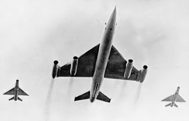
The Myasishchev M-50 with a MiG-21 escort, giving some perspective to the size of the M-50.
In general, the M-50 resembled an enlarged Mikoyan-Gurevich MiG-21. The M-50 was comprised of a long, slender fuselage with a large delta wing mounted in the middle. The fuselage had a circular cross-section with a bulge that ran down its spine for control and fuel lines. All fuel was housed in the fuselage and could be transferred between the extreme fore and aft tanks to counteract trim changes as the M-50 accelerated to or decelerated from supersonic flight.
The pilot and co-pilot sat in tandem at the very front of the aircraft. The M-50 was designed to operate at very high altitudes, and the crew was required to wear pressure suits in case of cabin depressurization or ejection. The aircraft was fitted with downward-ejecting seats. This configuration also facilitated crew entry and exit; the hatch under each seat opened and the seat lowered for access.
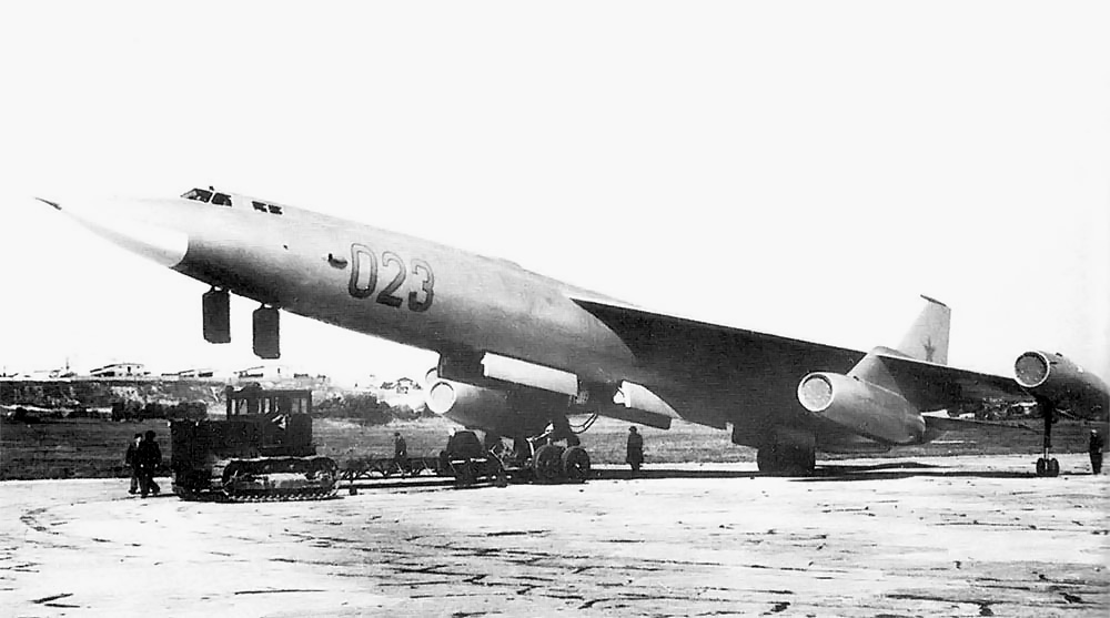
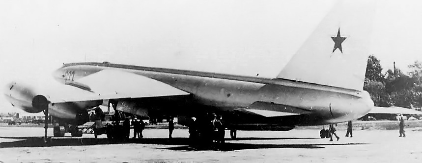
The M-50 with the hatches under the crew positions open. Also note the open bomb bay. The sole M-50 was painted with various radio call numbers.
The M-50’s wings were very thin and could not house any fuel. Under each wing was a pylon-mounted engine about 2/3 of the way toward the wingtip. On the top of the wing and above the engine pylon was a wing fence. Each wing had a second engine mounted at its tip. The wing was swept back 50 degrees from its root to the inboard engine and 41.5 degrees to the second engine at its tip (some sources say the sweep was 57.57 and 54.42 degrees respectively). The wing featured large, rectangular, double-slotted flaps and tapered outboard ailerons. Reportedly, when the flaps were deployed, the ailerons dropped down to further reduce the M-50’s landing speed. All three tail surfaces, including the vertical stabilizer, were all-moving. Each tail surfaces had an anti-flutter weight barb extending from its tip. All flight control surfaces were hydraulically operated.
The M-50’s landing gear was of bicycle configuration, with a four-wheel bogie located both fore and aft of the bomb bay. Additional forward retracting outrigger gear was mounted just inboard of each wingtip engine. In order to accommodate a weapons bay large enough to carry the 36 ft 1 in (11 m) long M-61 cruise missile, the rear main gear was placed near the tail, well behind the aircraft’s center of gravity. This gear placement drastically increased the speed needed for rotation at takeoff, perhaps even making takeoff impossible. To alleviate this issue, the M-50’s nose gear was equipped with a double-extension hydraulic strut. At 186 mph (300 km/h) the strut would automatically extend, rotating the aircraft 10 degrees nose-up. The gear also had an emergency steel skid that could be hydraulically lowered to the runway upon landing, acting as a drag anchor, in case there was an issue with the standard three-parachute braking system.
A rear view of the Myasishchev M-50 showing its all-movable tail surfaces. Also note the hump that housed fuel and control lines running along the aircraft’s spine.
The M-50 was 188 ft 7 in (57.48 m) long, had an 82 ft 4 in (25.1 m) wingspan, and was 27 ft 1 in (8.25 m) tall. The aircraft’s empty weight was 173,855 lb (78,860 kg), and its maximum weight was 319,670 lb (145,000 kg). The M-50’s forecasted performance included a service ceiling of 45,930 ft (14,000 m), a range of 8,075 mi (13,000 km), a bomb load of 11,000 lb (5,000 kg), and a top speed of 1,210 mph (1,950 km/h), or Mach 1.84.
Construction of the M-50 began in April 1956. Originally, the M-50 was to be powered by four Zubets RD-16-17 afterburning turbojets with 40,765 lb (181.32 kN) of thrust. However, the aircraft’s construction outpaced the engine’s development. When the M-50 was rolled out in July 1958, four non-afterburning Dobrynin VD-7BA turbojets of 21,495 1b (95.61 kN) thrust had been temporarily installed. The aircraft was re-designated M-50A as a result of the engine change.
In October 1958, the M-50A was disassembled and moved to the Zhukovskiy flight test center. Here it underwent taxi tests that indicated further modifications were needed. After the modifications, M-50A finally took to the air on 27 October 1959 with Nikolay I Goryainov and A S Lipko at the controls. Initial flight testing progressed rapidly; however, the M-50A was damaged in a ground accident on 12 May 1960. During an engine run-up, the aircraft jumped its wheel chocks and collided with the parked Myasishchev 3ME bomber prototype. The 3ME was scrapped as a result of the damage, but the M-50A was repaired and flying again in two months.

The Myasishchev M-50 makes a pass at the Tushino Air Show on 9 July 1961. Note the similar layout of the M-50 and its MiG-21 escorts.
In April 1961, the two inner VD-7BA turbojets were swapped with afterburning VD-7AM engines of 35,275 lb (156.91 kN) thrust. Slightly derated VD-7BA engines of 20,945 lb (93.16 kN) thrust were installed on new wingtip mounts. These mounts were wingtip extensions that housed new rearward retracting outrigger gear and increased the wingspan by 32 ft 10 in (10 m) to 115 ft 2 in (35.1 m). All engine installations were redesigned to incorporate ram inlets above the nacelle for additional cooling airflow.
Flight tests continued. With the underpowered engines installed, the M-50A was unable to achieve supersonic flight. Even in a shallow dive from altitude, the aircraft’s speed would not go above Mach 0.99, or 650 mph (1,050 km/h). In addition, the M-50A’s range fell 2,110 mi (3,400 km) short of expectations to 5,965 mi (9,600 km). During flight tests, the sole M-50A was painted with a various radio call numbers—023, 022, 12, and 05—to confuse any western observers.
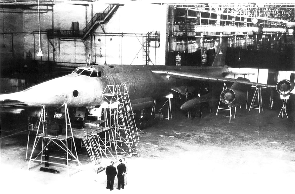
The Myasishchev M-52 mockup. Note the side-by-side cockpit configuration and the missile positioned near its mount under the wing. The small horizontal stabilizer is barely visible on top of the tail.
On 9 July 1961, the M-50A was escorted by two MiG-21 fighters as it made a flyby pass at the Tushino Air Show near Moscow. Western observers were impressed by the large, exotic, and loud aircraft. This appearance resulted in NATO assigning the codename “Bounder” to the M-50. However, what the observers did not know was that this was the M-50A’s last flight. It had only flown 19 times.
The M-52, a further development of the M-50, had been under construction since November 1958. The M-52 retained the four Zubets RD-16-17 engines (some say RD-17-18 engines rated at 39,020 lb / 173.58 kN). The wingtip engines were mounted on larger extensions. The M-52 had side-by-side seating for the pilot and co-pilot, and a third crew member was stationed in its nose. A small, delta-shaped horizontal surface was added to the top of the vertical stabilizer. Planned weapon upgrades for the M-52 included twin tail guns and provisions to attach a cruise missile on each side of its fuselage, under the wings.
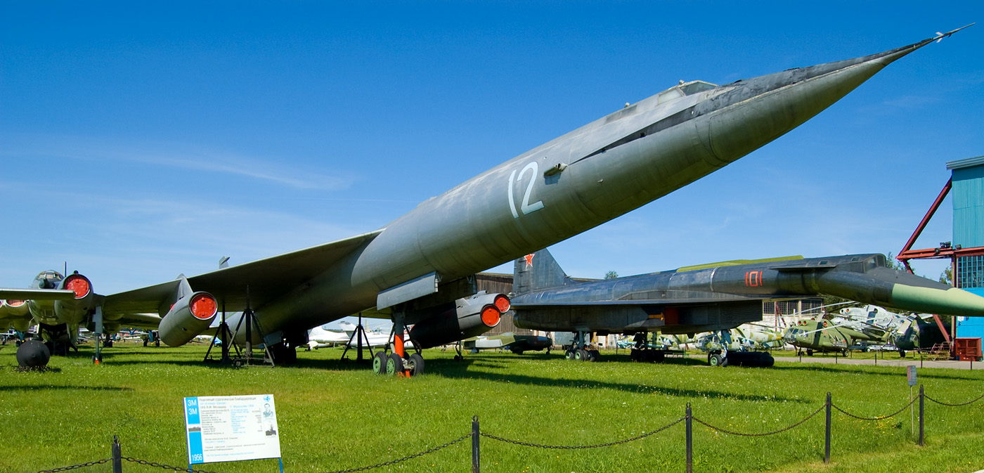
The Myasischev M-50 on display in the Central Air Force Museum at Monino Airfield. (Maarten image via Wikimedia Commons)
Soviet Premier Nikita Krushchev felt future offensive and defensive weapons would be based on intercontinental ballistic missiles (ICBMs) rather than strategic bombers. As a result, the Myasishchev M-50 and M-52 projects were cancelled. OKB-23 was closed, and its personnel were redirected to another organization for ICBM work.
The M-50A and the nearly finished M-52 eventually ended up parked at Ramenskoye Airport in Zhukovsky (near Moscow), Russia. In 1968, the M-50A was relocated to the Central Air Force Museum at Monino Airfield (also near Moscow) where it is currently on display. The M-52 was scrapped in the 1970s.
Below is a video of the Myasishchev M-50 uploaded to YouTube.
Sources:
– Soviet X-Planes by Yefim Gordon and Bill Gunston (2000)
– Aircraft of the Soviet Union by Bill Gunston (1983)
– http://www.airvectors.net/avbison.html
– http://www.testpilot.ru/russia/myasishchev/m/50/m50_e.htm
– http://www.testpilot.ru/russia/myasishchev/m/52/m52.htm
– Unflown Wings by Yefim Gordon and Sergey Komissarov (2013) *No real info on the M-50 or M-52 but does contain a number of other projects that are often attributed to these aircraft.