Monthly Archives: September 2014

Marchetti MP Cam Action

Marchetti Cam-Action Engines

By William Pearce

Paul J. Marchetti was born in Italy in 1889. In his adolescence, he became interested in machines, engineering, and aircraft. In 1910, when he was 21 years old, Marchetti emigrated from Lucca, Italy to the United States in search of greater opportunities. He worked his way west and supported himself as a logger, all the while dreaming of entering the aviation business.

Marchetti MP Cam Action side

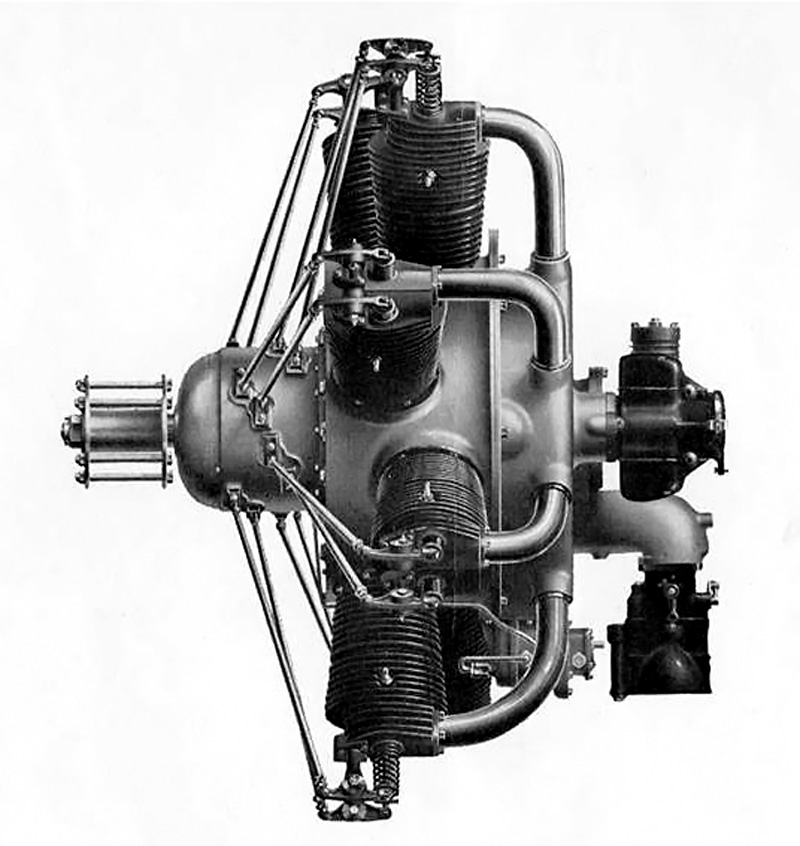
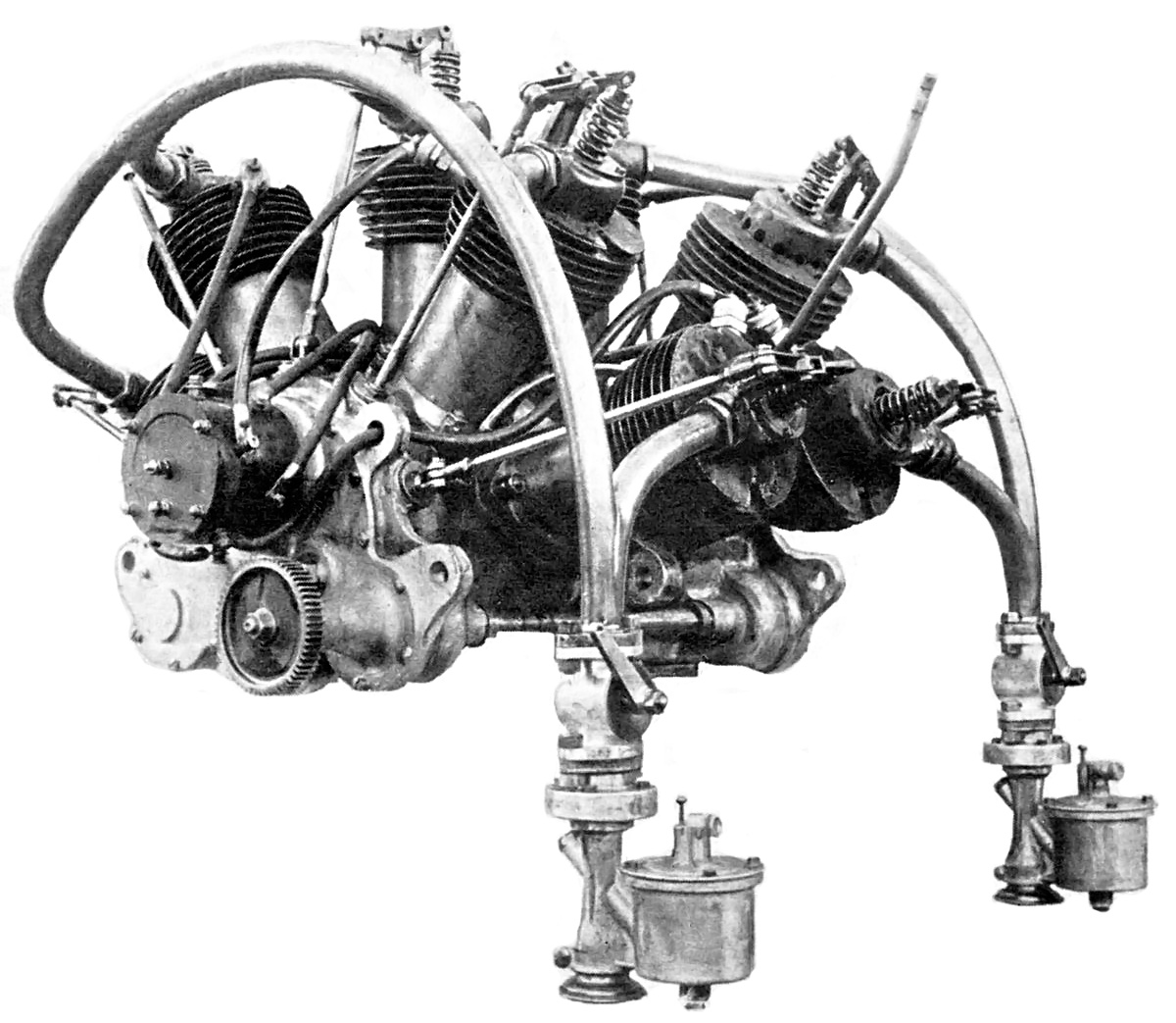
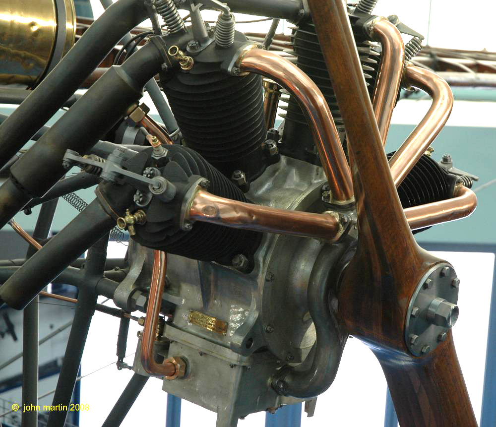
The Marchetti eight-cylinder, cam-action aircraft engine of 1927. Note the stagger of the front and rear cylinders.

Unfortunately, there is little information about Marchetti, his life, and his inventions. By 1922, he was working with Henry A. Nordwick in Stockton, California. Nordwick was working on designing a radial engine in which the crank throw was replaced by a cam with four lobes. A roller on the big end of the connecting rod made contact with the cam, its points creating the piston strokes. Another Nordwick and Marchetti engine design dating from 1923 had the big end of each connecting rod attached to its own crank, which was geared to a main central gear.

By 1924, Marchetti was in San Francisco, California and filed a patent of his own for a broad-arrow engine using either a three- or four-lobe cam in place of the crankshaft. Still working with Nordwick, another patent was filed for an eight-cylinder radial with a two-lobe cam. A lever extended from the big end of each connecting rod and was attached to the crankcase. Also connected to this lever was an auxiliary piston. Fed by pressurized air, the auxiliary piston forced the connecting rod to be in contact with the cam at all times. One auxiliary piston was positioned between each main piston.

Nordwick Marchetti cam engine patents

Drawings from Nordwick and Marchetti cam engine patents. The patent for the four-lobe cam design (left) was filed in 1922, and the patent for the eight-cylinder engine with auxiliary pistons (right) was filed in 1924.

Nordwick and Marchetti focused on inline engines in 1925. They designed a two-lobe cam engine, again using a lever extending from the big end of the connecting rod to the crankcase. That same year, Marchetti patented an inline engine under his business name: Marchetti Motor Patents. For this engine, the crankshaft throws were replaced with disks, offset to the crankshaft’s centerline. A connecting rod ran in a grove in each disk, and the disk’s offset would create the up and down strokes for the piston. The circular disk could also be substituted in favor of a lobed design for increased engine performance.

In 1926, Marchetti took out a patent on an inline engine with a two-lobe cam driving the pistons. The connecting rods were paired together via a rocker so that when one piston was at top dead center the other piston would be at bottom dead center. This configuration was also suggested for a U engine with two separate cam (crank) shafts.

Marchetti Motor Patents

Drawings from the Marchetti cam engine patents. The 1924 broad-arrow engine design is on the left, and the 1925 inline cam disk design is on the right.

1927 saw Marchetti focus on the business side of his dreams. His company, Marchetti Motor Patents, Inc., was officially formed with $2,000,000 of capital and operated out of the newly completed Russ Building, the tallest building in San Francisco until 1964. Marchetti worked on new engines and aircraft. In 1928, ground was broken for the Marchetti Motor Patents factory at Mills Field (now San Francisco International Airport). The factory had an expected output of 100 aircraft and 1,000 engines per year.

With his business established, Marchetti designed and built a new cam engine. While incorporating some aspects of the previous engine designs, this engine also had some unique features that are not found in any of the patents filed by Marchetti. However, the connecting rod arrangement and cam were similar to those found in a patent filed solely by Nordwick in 1926.

Marchetti MP info

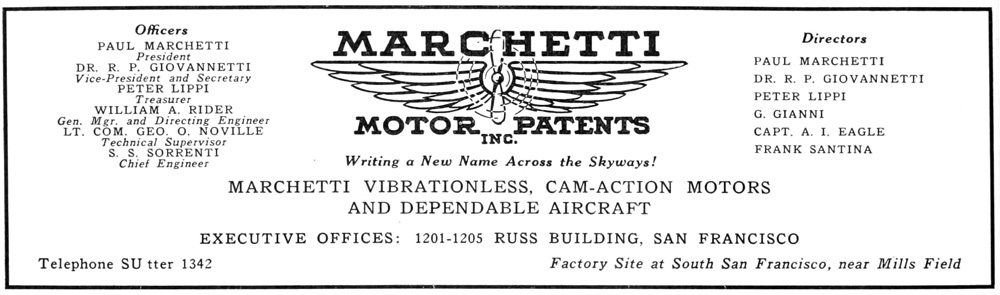
Marchetti Motor Patents Inc. advertisement from 1929.

The new engine was an air-cooled, eight-cylinder radial. The cylinders were slightly staggered, making two rows of four cylinders. Twin two-lobe cams replaced the conventional crankshaft. Via roller bearings, the front cam actuated the connecting rods for the front cylinders, and the rear cam actuated the connecting rods for the rear cylinders. One fore and one aft cylinder were paired together by a common bell crank attached to the big end of the connecting rods. The center of this bell crank was the pivot point and was attached to the crankcase. The cams were staggered so that when one of the paired cylinders was at top dead center, the other cylinder was at bottom dead center. Since each cam had two lobes, there would be four piston strokes (or one power stroke) for each revolution. Marchetti referred to this design as a “cam-action” engine.

Each of the engine’s cylinders had one intake and one exhaust valve at the center of its head. The valves were actuated by pushrods driven at the front of the engine. Two spark plugs were located just below the valves of each cylinder and were fired by a magneto driven from the rear of the engine. A carburetor attached to the lower rear of the engine fed the air/fuel charge into a blower (weak supercharger). The blower helped mix the air/fuel charge, which was then distributed to the cylinder via separate manifolds. The engine had a 4.0 in (102 mm) bore, a 4.25 in (108 mm) stroke, and a total displacement of 427 cu in (7.0 L). Initially, 135 hp (101 kW) was expected from the engine, but 160 hp (119 kW) was achieved after testing. The engine weighed 350 lb (159 kg).

Marchetti MP Cam Action

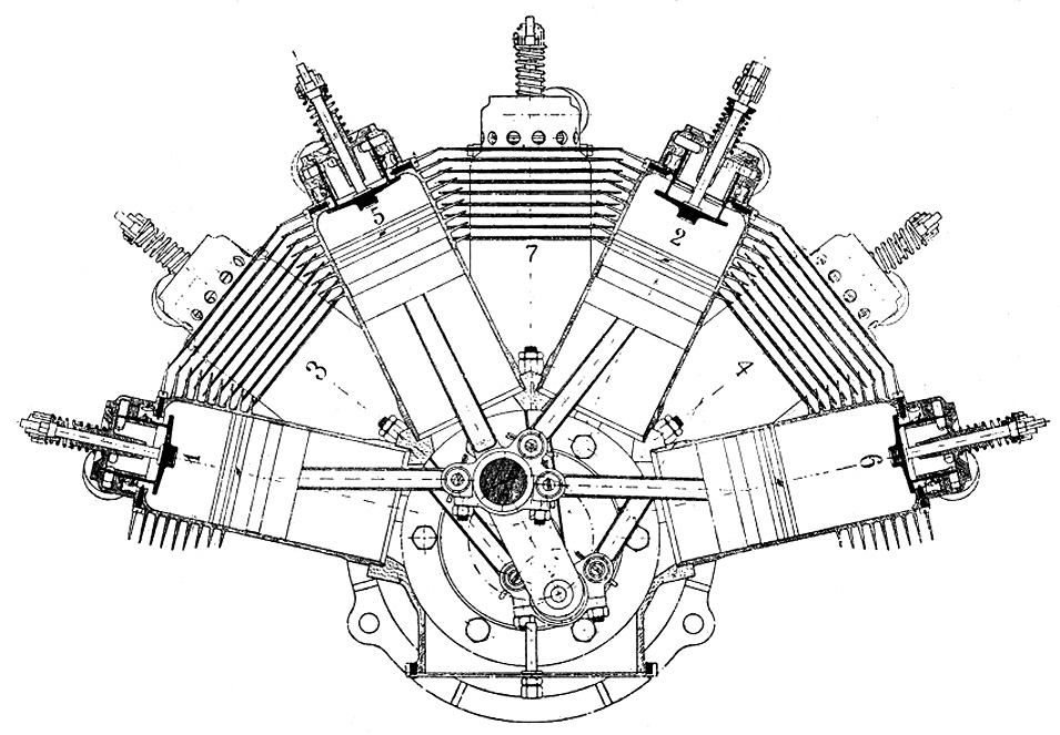
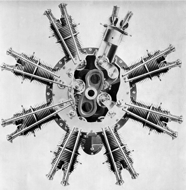
Cutaway view of the Marchetti cam-action engine. The rear cam can barely be seen in the rear of the crankcase. Note how each cam actuates one “row” of cylinders. The bell crank for the upper right cylinder pair can be seen clearly. The bell crank attached to the connecting rods and pivoted in the middle, where it was mounted to the crankcase.

The eight-cylinder engine was first run in 1927. Most sources say only one engine was built, but some claim more were built. The engine passed a 400 hour maximum load test, and 2,200 hours were accumulated with no apparent signs of wear. Marchetti modified a Cessna AW for flight testing the eight-cylinder radial, but it is not known if the engine was ever installed. This aircraft was designated Marchetti M-I

Marchetti MP M-II Arrow advert

Advertisement from September 1929 for the Marchetti M-II Arrow and its four-cylinder engine cam-action engine.

Another Marchetti aircraft was the M-II Arrow—a two-place monoplane to be powered by a Marchetti inline, four-cylinder, air-cooled, cam-action engine of 100 hp (75 kW). The M-II was constructed of wood covered by fabric. On the drawing board was the Marchetti M-III—an eight passenger, all metal aircraft intended for passenger service. It was to be powered by two Marchetti eight-cylinder cam-action radials.

With his aircraft and aircraft engine manufacturing plans underway, Marchetti continued to chase his dream of becoming a pilot. On 31 August 1929, one week before the plant opened, Marchetti took off from Mills Field to look over his nearly finished factory and log some of the two hours remaining before he could get his pilot’s license. He flew into a fog bank, and what happened next is not known. A short time later, Marchetti’s aircraft was seen falling from under the fog bank in an inverted flat spin. The aircraft crashed half a mile (.8 km) from shore into San Francisco Bay. Rescue boats reached the scene as fast as possible, but it was too late. Marchetti’s body was found in the submerged fuselage.

The Marchetti M-II Arrow was completed and flown, but it is not known which engine powered it. While it is possible that it flew with a Marchetti inline cam engine, it is more likely that another four-cylinder engine was installed. Marchetti’s grand aviation plans drifted into oblivion after his death. Marchetti Engine Patents Inc. was sold to William Rider and then resold to United Aircraft Sales where it faded to obscurity. What happened to the M-I, M-II Arrow, or any of the cam-action test engines is not known. It is believed that the M-III transport never progressed beyond the design phase.

Marchetti MP M-II Arrow

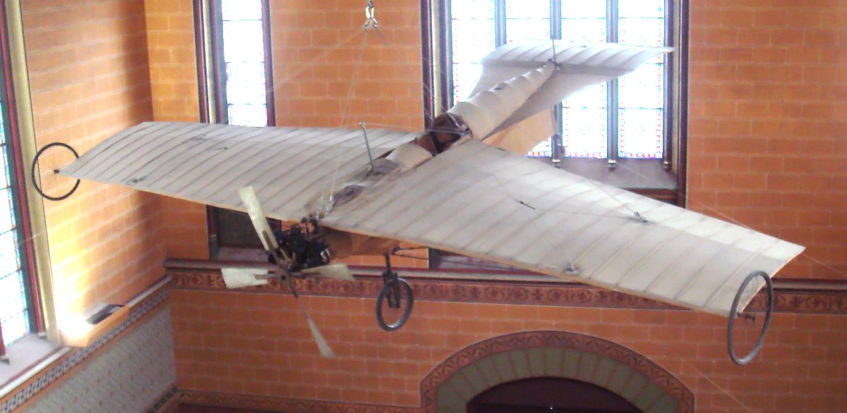
The complete Marchetti M-II Arrow with its unidentified engine. The aircraft carried the registration X-98M. (Frank Rezich image via www.aerofiles.com)

Sources:
– “Falls to Death: Paul Marchetti” Oakland Tribune (1 September 1929)
– “Marchetti Motor to Revolutionize Airplane Industry” Ukiah Dispatch Democrat (12 May 1928)
– “The Business of Building Aircraft” San Francisco Business (11 September 1929)
– “Internal Combustion Engine” US patent 1,374,164 by H. A. Nordwick (granted 5 April 1921)
– “Internal Combustion Engine” US patent 1,528,164 by H. A. Nordwick (granted 3 March 1925)
– “Internal Combustion Motor” US patent 1,538,208 by H. A. Nordwick et al (19 May 1925)
– “Engine” US patent 1,654,378 by P. Marchetti (granted 27 December 1927)
– “Internal Combustion Engine” US patent 1,597,474 by H. A. Nordwick et al (granted 24 August 1926)
– “Internal Combustion Engine” US patent 1,624,277 by H. A. Nordwick et al (granted 12 April 1927)
– “Internal Combustion Motor” US patent 1,667,213 by P. Marchetti (granted 24 April 1928)
– “Motor” US patent 1,624,269 by P. Marchetti (granted 12 April 1927)
– “Duplex Cam Motor” US patent 1,630,273 by H. A. Nordwick (granted 31 May 1927)
Aerosphere 1939 by Glenn Angle (1940)
http://www.aerofiles.com/_ma.html

REP 7-cylinder

R.E.P. Fan (Semi-Radial) Aircraft Engines

By William Pearce

Robert Esnault-Pelterie was born in France on 8 November 1881. In the early 1900s, he began experimenting with a glider modeled after the Wright Brothers’ glider of 1902. Esnault-Pelterie had experienced trouble with the Wrights’ wing warping technique and switched to ailerons in 1903. In 1906, Esnault-Pelterie began constructing a powered aircraft of his own design as well as an engine to power it. Esnault-Pelterie named the aircraft the R.E.P. 1 and it first flew in 1907. A new feature of the aircraft was a control stick, which Esnault-Pelterie patented. That patent made Esnault-Pelterie a rich man once royalties were paid after World War I. While the unique engine that he designed was the first in a family of engines known as R.E.P., their success would not endure like that of the control stick.

REP 7-cylinder

Front view of the R.E.P. seven-cylinder fan engine. Exhaust gases flowed out the holes around the top of the cylinders. The intake manifold can barely be seen behind the cylinders. In this view, the four cylinders on the right shared an intake manifold as did the three cylinder on the left.

Esnault-Pelterie’s first engine was an air-cooled, seven-cylinder fan engine. Sometimes referred to as a semi-radial, this engine had cylinders that were fanned-out on the top of the crankcase and not positioned around its entirety like a true radial. The cylinders were arranged in two rows—the front had four cylinders, and the rear had three cylinders. This configuration solved lower cylinder lubrication issues of radial engines, and air-cooling issues of inline engines.

The cast iron cylinders were attached to an aluminum crankcase. The upper part of the cylinder had cooling fins to dissipate heat. At the very top of the cylinder was a large, single valve. The valve was shaped like a piston and inverted, with the valve stem attached to underside of the head. When the valve was completely closed, a flange on its head would seat against the cylinder head and seal the cylinder. When the valve was partially open, exhaust gases flowed around the flange and escaped through ports in the cylinder head. When the valve was completely open, ports in its sides aligned with ports in the cylinder head to allow the intake mixture to flow into the cylinder.

REP 7-cylinder section

In this section view of the R.E.P. seven-cylinder engine, the cylinders are numbered by firing order. Cylinder 5 has the intake/exhaust valve completely closed. Cylinder 1 shows the valve partially open to allow exhaust gases to exit the cylinder. Cylinder 2 shows the valve completely open to allow the air/fuel mixture into the cylinder. Note the master/articulated connecting rod arrangement.

The valve was actuated by a rocker arm attached to the cylinder. The rocker arm was moved via a pushrod that was operated by a cam ring inside the engine. Each row of cylinders had its own cam ring positioned at the rear of the engine, and the cam rings had stepped lifts. The first step opened the valve part way to allow the exhaust gases to vacate the cylinder. The second, higher lift completely opened the valve to allow the fresh air/fuel mixture into the cylinder. For the intake, the cylinders were separated into left and right groups, with the left group (when viewing the engine from the rear) having an additional cylinder. Each group shared a common intake manifold with a carburetor attached to its end. The intake manifold was attached to the upper rear of the cylinder. Exhaust gases flowed out though ten holes around the cylinder’s top; there were no exhaust stacks.

A single spark plug was installed in the side of the cylinder and fired by an ignition coil powered by a battery. The pistons were made of steel and had two oil rings. They were attached to the connecting rods by trunnions bolted to the underside of the piston. The connecting rod for each row of cylinders had one master rod, and the rest were articulating rods. The crankshaft had two throws offset 180 degrees and was supported by two main bearings. To balance the crankshaft, Esnault-Pelterie left the crankpin solid for the row with an additional cylinder, and the crankpin for the row with one fewer cylinder was drilled hollow.

REP 10-cylinder side

This side view of the R.E.P. 10-cylinder engine illustrates how it was comprised of two five-cylinder engines bolted front-to-front. Note the rocker arm arrangement and the single valve. The pictured engine was equipped with magnetos.

The engine had a 3.35 in (85 mm) bore and 3.74 in (95 mm) stroke. The seven cylinders displaced a total of 230 cu in (3.8 L). The engine produced 30 hp (22 kW) at 1,500 rpm and weighed 150 lb (68 kg). A five-cylinder version was also built with three cylinders in the first row and two in the second. It produced 20 hp (15 kW) at 1,500 rpm from its 164 cu in (2.7 L) and weighed 118 lb (54 kg). Another version consisted of two five-cylinder engines joined at their front to create a 10-cylinder engine. Each engine group had its own intake manifold feeding five cylinders. The 10-cylinder engine produced 50 hp (37 kW) at 1,500 rpm from its 329 cu in (5.4 L) and weighed 214 lb (97 kg). Some sources indicate the same coupling treatment was applied to the seven-cylinder engine to create a 14-cylinder engine, but this cannot be confirmed. A 14-cylinder engine would have displaced 461 cu in (7.5 L) and produced around 70 hp (52 kW).

The five- and seven-cylinder engines powered a number of early aircraft (R.E.P.s, Bléroits, Kapferer-Paulhans, and Breguets), but it is unlikely the 10-cylinder engine ever flew. Esnault-Pelterie received an award in 1908 from the Société des ingénieurs civils de France (Society of Civil Engineers of France) for his seven-cylinder R.E.P. engine. However, the cylinder’s single valve proved unsatisfactory, and the engines were redesigned in 1909.

REP 10-cylinder back

Rear view of the R.E.P. 10-cylinder engine equipped with a coil ignition. Note that each engine section has its own intake manifold and carburetor.

The updated engines had two valves per cylinder, but they were still operated by a single rocker arm. The intake valve was in the front of the cylinder, and the exhaust valve was in the rear. The rocker arm pivoted between the valves so that it pushed the intake valve open and then rocked back to pull down on the exhaust valve to open it. This was achieved by a grooved cam-disc that could “pull” and “push” the pushrod.

The engine’s bore and stroke were increased to 3.94 in (100 mm) and 5.51 in (140 mm). The five-cylinder engine displaced 335 cu in (5.5 L) and produced 60 hp (45 kW) at 1,400 rpm. The seven-cylinder engine displaced 470 cu in (7.7 L) and produced 90 hp (67 kW) at 1,400 rpm. There is no indication that any attempt to couple the engines was made. The cylinders had revised cooling fins, and the spark plug was repositioned to the cylinder head. Magnetos were used in place of the coil ignition.

REP 5-cylinder Type D

An updated R.E.P. five-cylinder engine preserved in a R.E.P. Type D monoplane at the Musée de l’Air et de l’Espace. Note the two valves per cylinder and rocker arm arrangement. The unique induction system can be seen in which it drew air from the crankcase and delivered it to the cylinders via the copper pipes. The individual exhaust pipes can be seen at the rear of the engine. (John Martin image via the Aircraft Engine Historical Society)

Induction and exhaust were also updated. Intake air was fed from the crankcase (where it was warmed), through a distributor, and then to the front of each cylinder. Exhaust gases were collected in pipes at the rear of each cylinder and directed away from the cockpit. The many changes increased the weight of the engines to 243 lb (110 kg) for the five-cylinder and 287 lb (130 kg) for the seven-cylinder. The updated R.E.P. fan engine had no trouble running for 10 hours non-stop during various bench tests.

The five-cylinder engine seemed the more successful of the two and was installed in a number of aircraft (R.E.P.s and Farman-Neubauers). It was used in the Vickers R.E.P., which was the first aircraft made by Vickers and would have been the first aircraft to fly in Antarctica had its wings not been damaged during a demonstration flight in Australia. Even so, the wingless Vickers was taken to Antarctica and used as a powered sled, but with not much success. The remains of this aircraft were rediscovered there in January 2010.

Vickers REP in Antarctica

The Vickers R.E.P. in Antarctica in 1911. The engine clearly has two valves per cylinder and the unique induction system of the updated fan engine.

In 1911, Esnault-Pelterie refocused his design efforts on true radial engines, constructing five- and seven-cylinder engines. The fan/semi-radial engines were phased out in 1912. Over the next few years, Esnault-Pelterie stopped designing piston engines as he became more interested in rocketry. A few R.E.P. fan engines still exist in museums, including a seven-cylinder engine in Esnault-Pelterie’s original R.E.P. 1 aircraft from 1907 displayed at the Musée national des Arts et Métiers (National Museum of Arts and Crafts) in Paris, France. This museum may also hold another original seven-cylinder engine cutaway. An updated five-cylinder engine exists installed in an uncovered R.E.P. Type D monoplane from 1910 at the Musée de l’Air et de l’Espace (Air and Space Museum) in Le Bourget, France.

Note: Many sources list a variety of different bore and stroke combinations for the R.E.P. fan engines. Some sources list some of the early engines as having a 3.54 in (90 mm) stroke, while others list the updated engines as having a 4.33 in (110 mm) bore or 6.30 in (160 mm) stroke. While it is possible that such bore and stroke combinations were built, little supporting information has been found.

REP 1 with 7-cylinder engine

Esnault-Pelterie’s original R.E.P. 1 aircraft and its engine preserved in the Musée national des Arts et Métiers. (PHGCOM image via Wikimedia Commons)

Sources:
– “Moteur Extra-Léger a Explosion” by Robert Esnault-Pelterie, Mémoires et Compte Rendu des Travaux de la Société des ingénieurs civils de France Bulletin (December 1907)
Les aéroplanes et moteurs R.E.P. by Gérard Hartmann (4 MB pdf)
Les Moteurs a Pistons Aeronautiques Francais Tome I by Alfred Bodemer and Robert Laugier (1987)
– “The First Paris Aeronautical Salon: Engines for Aeroplanes” Flight (16 and 23 January 1909)
Aero Engines by G. A. Burls (1916)
http://aviatechno.net/bib/001n_les_moteurs_aviation.php
http://www.nmspacemuseum.org/halloffame/detail.php?id=7
http://en.wikipedia.org/wiki/Vickers_R.E.P._Type_Monoplane