By William Pearce
In early 1939, Soviet authorities sought the design and development of a new aircraft engine rated in excess of 2,000 hp (1,491 kW). Soviet aircraft engine technology was falling behind that of the western powers at the time, and this new engine was intended to close the gap. Gleb S. Skubachevskiy at the Moskovskiy Aviatsionniy Institut (Moscow Aviation Institute or MAI) completed the preliminary design of the new 2,000+ hp (1,490+ kW) engine, and development of a prototype was approved in July 1939. The new engine was given the designation M-250. Vladimir A. Dobrynin was brought in to assist Skubachevskiy on the M-250.
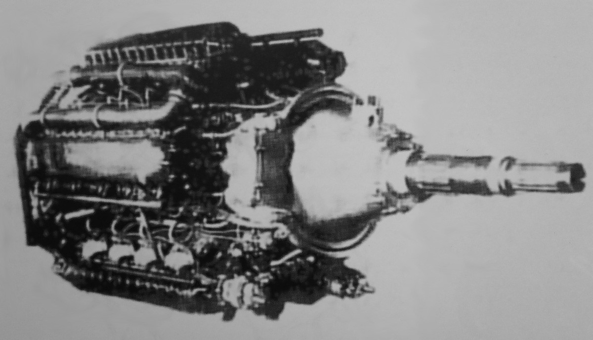
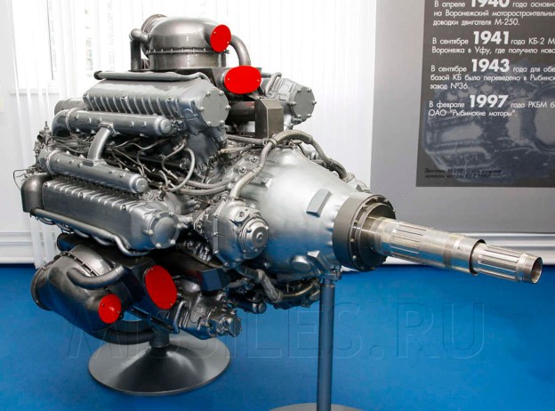
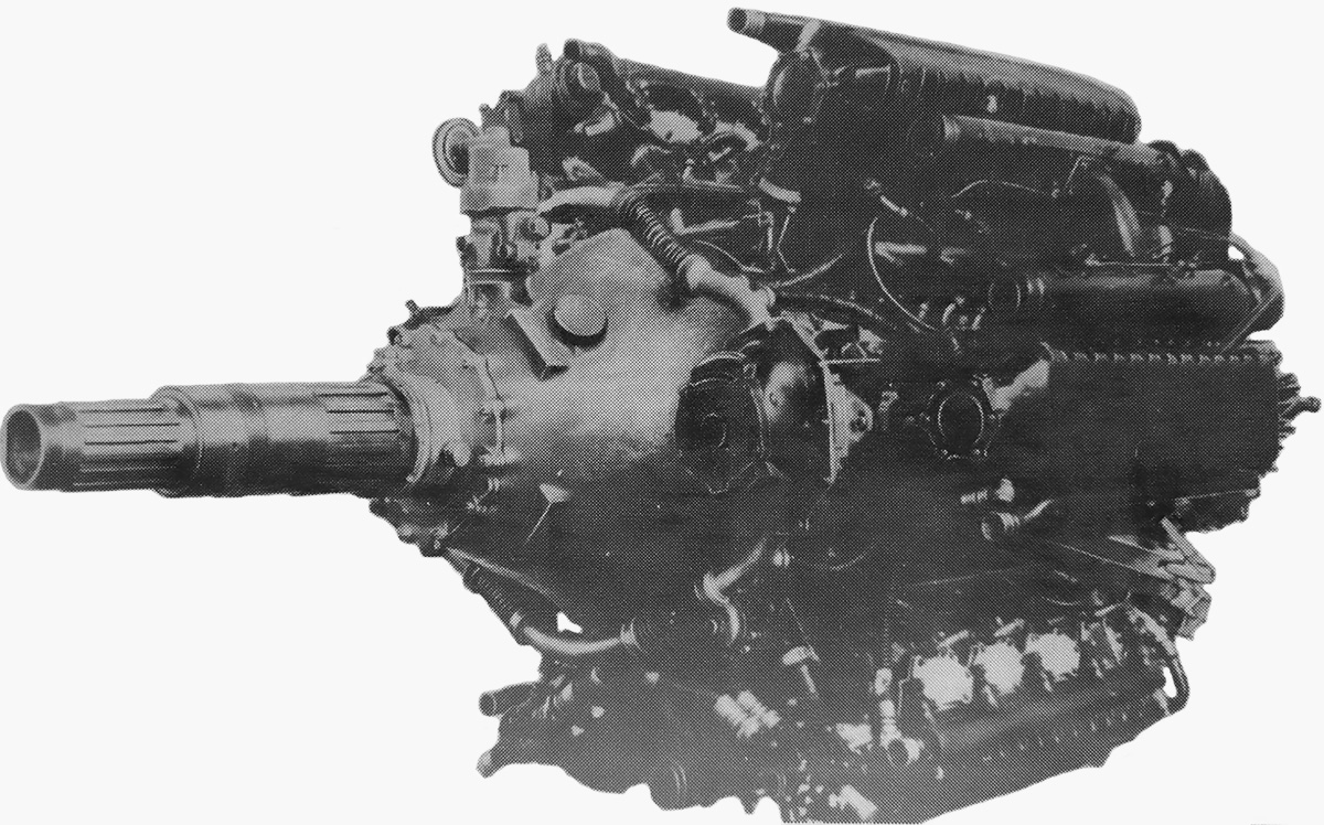
The six bank, 24-cylinder, 3,111 cu in (51.0 L) M-250 aircraft engine with contra-rotating propeller shafts.
The M-250 was a 24-cylinder, water-cooled engine with six cylinder banks, each with four cylinders. The inline cylinder banks were spaced radially around the crankcase at 60 degree intervals, giving the engine an inline radial configuration. One cylinder bank extended horizontally from the crankcase on each side of the engine. A hexagon was formed by connecting the outer points of the six cylinder banks, making the M-250 part of the hexagonal engine family. Other hexagonal engines include the Curtiss H-1640 Chieftain, the Wright H-2120, the SNCM 137, and the Junkers Jumo 222. The M-250 employed a master/articulating connecting rod arrangement as used in a typical radial engine. The engine had a single-stage, three-speed supercharger mounted at its rear. A carbureted version of the engine was built along with a direct fuel injected version. The engine had a compression ratio of 6.2 to 1.
Each cylinder bank had a single overhead camshaft that was driven by a vertical shaft at the front of the bank. Intake and exhaust manifolding occupied the space between alternating cylinder banks, and the spark plugs were located in the intake Vee. At the front of the engine, the crankshaft drove contra-rotating propeller shafts via a reduction gearing. The M-250 had a 5.5 in (140 mm) bore and a 5.4 in (138 mm) stroke. The total displacement from the 24-cylinder engine was 3,111 cu in (51.0 L), and the engine weighed 2,822 lb (1,280 kg). The M-250 produced 2,200 to 2,500 hp (1,640 to 1,864 kW).
The M-250 was developed into the 3,628 cu in (59.5 L), 3.500 hp (2,610 kW) Dobrynin VD-3TK.
Dobrynin was sent to Voronezh, Russia to assist with the M-250’s construction and testing while Skubachevskiy remained at the MAI. The M-250 was first run on 22 June 1941. However, the M-250 development team was evacuated from Voronezh in October 1941 because of advancing German troops. Skubachevskiy was also evacuated from the MAI in Moscow and was no longer involved with the M-250 as a result. After the evacuation from Voronezh, the M-250 design team and the manufacturing team were split, which caused long delays in further engine testing and the completion of additional prototypes.
M-250 development and testing was continued at what later became OKB-36 (Opytno-Konstruktorskoye Byuro-36 or Experimental Design Bureau-36) in Rybinsk, Russia. However, the M-250 engine program was never able to fully recover after the evacuation, and the project was cancelled on 25 June 1946. A total of 10 M-250 prototype engines were built. The M-250 engine was proposed for use in several projects: a version of the Ilyushin Il-2 Sturmovik attack aircraft, an undesignated Yakovlev heavy fighter, the Alekseyev I-218 attack aircraft, and an undesignated Alekseyev fighter. However, none of these projects progressed beyond the drawing board, and the M-250 was never installed in any aircraft.
A Tupolev Tu-4LL testbed with a contra-rotating Dobrynin VD-3TK engine installed in each outer position. The LL in the aircraft’s designation stood for “letayushchaya laboratoriya,” which means flying laboratory.
While at OKB-36 and under Dobrynin’s supervision, A. L. Dynkin developed the M-251TK from the M-250. Compared to the M-250, the M-251TK had a larger bore and stroke, a higher compression ratio of 6.6 to 1, and strengthened internal components. In addition, the engine was fitted with fuel injection, a single-speed supercharger, and two turbosuperchargers. Two versions of the M-251TK were developed—one with a standard propeller shaft and one with contra-rotating propeller shafts.
After the M-250 was cancelled, the M-251TK was approved for prototype manufacture in late 1946 and was first run in August 1947. The M-251TK passed various certification tests throughout 1948, including 50 and 100 hour tests. The engine was approved for manufacture in January 1949 as the VD-3TK. The VD-3TK had a 5.8 in (148 mm) bore and a 5.7 in (144 mm) stroke. The engine’s total displacement was 3,628 cu in (59.5 L), and it weighed 3,351 lb (1,520 kg). The VD-3TK had a takeoff rating of 3,500 hp (2,610 kW) and a continuous rating of 2,500 hp (1,864 kW).

The restored Dobrynin VD-4K engine preserved at the CPO Saturn facility in Rybinsk, Russia. The power recovery turbines are mounted in the exhaust Vees of the engine. The red plates cover inlets through which air flowed to cool the units. The 4,300 hp (3,207 kW) VD-4K represented the pinnacle of piston-engine development in the Soviet Union. (www.missiles.ru image)
In the first half of 1950, VD-3TK engines were test-flown in the outboard positions on a Tupolev Tu-4 bomber. The engine was also proposed for the Alekseyev Sh-218 attack aircraft, which was never built. The VD-3TK did not enter series production, and only 34 engines were made.
In 1949, Dobrynin’s team at OKB-36 had begun further engine development, this time based on the M-251TK. The intent was to create an engine with improved fuel economy to be used for a new long range, strategic bomber. The new engine was known as the M-253K, and its development proceeded under chief designer P. A. Kolesov. Along with other modifications, the engine’s compression ratio was raised to 7.0 to 1, and three power recovery turbines were installed in the exhaust Vees. These turbines would recover energy from the exhaust gases and feed that power back to the engine’s crankshaft. The two turbosuperchargers used with the M-251TK engine were replaced by a single, large unit that incorporated an adjustable jet outlet to harness thrust from the exhaust gases.
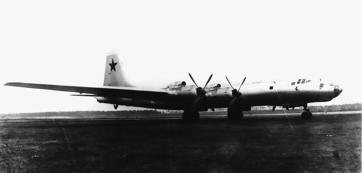
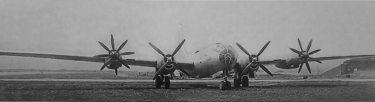
The Tupolev Tu-85 strategic bomber was the only aircraft powered by VD-4K engines. The engines and aircraft preformed well, but the future lay with turboprop and jet engines. Note the turbosupercharger housing above each engine nacelle.
The first M-253K was completed in January 1950. Prototype engines were tested and developed throughout 1950. During this time, test engines passed 50 and 100 hour tests and were flown as the No. 3 engine on a Tu-4. Twenty-three engines were built and given the designation VD-4K. While the VD-4K had the same bore and stroke as the VD-3TK, the VD-4K produced a lot more power. The engine had a takeoff rating of 4,300 hp (3,207 kW) at 2,900 rpm and a continuous rating of 3,800 hp (2,834 kW) at 2,700 rpm. The VD-4K was fuel injected and achieved a specific fuel consumption of .408 lb/hp/hr (284 g/kW/hr) at cruse power. The engine was 63 in (1.6 m) in diameter, 119 in (3.0 m) long, and weighed 4,552 lb (2,065 kg). The turbosupercharger weighed an additional 485 lb (220 kg).
VD-4K engines were installed in Tupolev’s new strategic bomber, the Tu-85. The Tu-85 was ordered in 1949 and made its first flight on 9 January 1951—Aleksei Perelyot was at the controls. The Tu-85 had a 183.5 ft (55.9 m) wingspan and was 130.9 ft (39.9 m) long. The aircraft had a maximum speed of 396 mph (638 km/h) at 32,810 ft (10,000 m). Designed to counter the long-range Convair B-36 Peacemaker, the Tu-85 could deliver 11,000 lb (1,000 kg) of bombs 7,580 mi (12,300 km) or carry 44,000 lb (20,000 kg) of bombs.

A diagram showing the VD-4K’s installation in the Tu-85 and its intake and exhaust paths. Note the cooling fan and how air is diverted from the turbosupercharger inlet to flow through an aftercooler.
In the Tu-85, an annular radiator was installed around the front of the VD-4K engine. An axillary fan was added behind the spinner to increase the flow of cooling air, but it appears no other major improvements were needed. The turbosupercharger for the VD-4K engine was positioned on top of the nacelle, and the engine exhaust flowed back over the wing. Incoming air to the engine was compressed by the turbosupercharger, flowed through an aftercooler, and was then delivered to the engine.
While the Tu-85 and its VD-4K engines achieved excellent test results, the Tupolev Tu-95 “Bear” strategic turboprop bomber was under development and showed greater promise than the Tu-85. As a result, development of the Tu-85 and the VD-4K engine was stopped. Both Tu-85 prototypes were later scrapped.
The VD-4K was the last piston engine developed by Dobrynin and OKB-36; their efforts shifted to designing and building turbojets engines. A VD-4K engine is preserved at the NPO Saturn (former OKB-36) facility in Rybinsk.
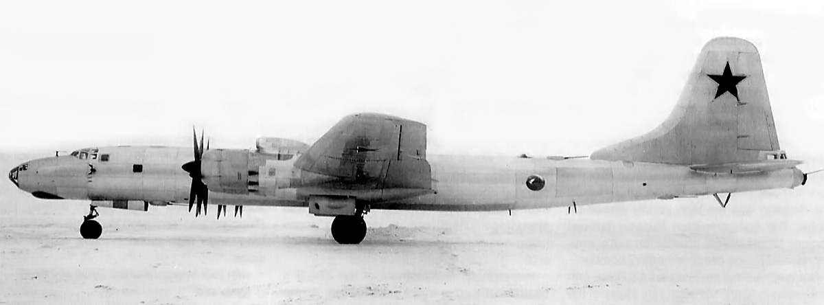
With its impressive range and payload, the Tu-85 was one of the most capable piston-engine bombers ever built. Because of the transition to turbine engines, the Tu-85 was outclassed and never went into production.
Sources:
– Russian Piston Aero Engines by Vladimir Kotelnikov (2005)
– Unflown Wings by Yefim Gordon and Sergey Komissarov (2013)
– Soviet and Russian Testbed Aircraft by Yefim Gordon and Dmitriy Komissarov (2011)
– Tupolev Aircraft since 1922 by Bill Gunston (1995)
– http://www.redov.ru/transport_i_aviacija/aviacija_i_kosmonavtika_1997_07/p3.php