Monthly Archives: August 2015

Reggiane Re 103 left side 1943

Reggiane Re 101 to Re 105 Aircraft Engines

By William Pearce

In 1936, the Italian aircraft manufacturer Officine Meccaniche Reggiane (Reggiane) branched out to produce aircraft engines. Initially, Reggiane produced Piaggio and FIAT engines under license, but it was not long before the company began to develop its own aircraft engines. As world events unfolded in the 1940s, only one model of Reggiane’s aircraft engines was built, and it did not proceed beyond the testing phase.

Reggiane Re 103 April 1942

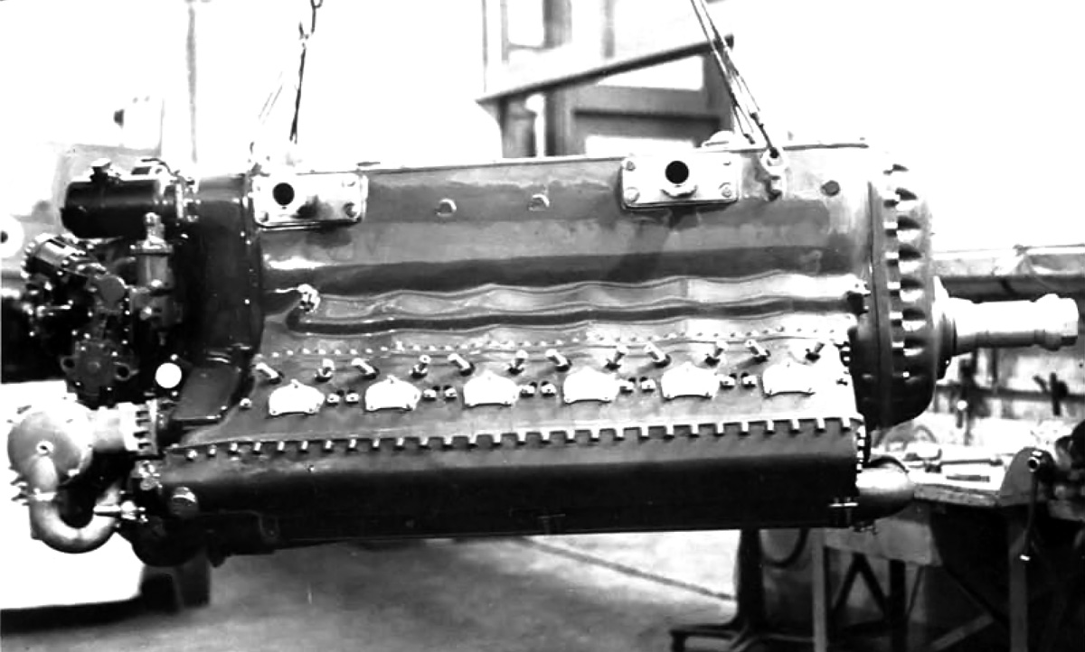
The Reggiane Re 103 RC50 I engine in April 1942 before spark plug wires and fuel lines were added. Note the two spark plugs per cylinder.

Reggiane’s first aircraft engine design was the Re 101 RC50 I*. The “R” in the engine’s designation meant that it had gear reduction (Riduttore de giri); the “C” meant that it was supercharged (Compressore); the “50” stood for the engine’s critical altitude in hectometers (as in 5,000 meters), and the “I” meant the engine was inverted (Invertita). Occasionally, a letter was added to designate the engine’s configuration, as in “L” for inline (Linea) appearing as Re L 101 RC50. Proposed in the late 1930s, the Re 101 RC50 I was an inverted, liquid-cooled V-12 of 1,635 cu in (26.8L). Although its bore and stroke have not been found, they were probably around 5.51 in (140 mm) and 5.71 in (145 mm) respectively. The engine produced 1,200 hp (895 kW) for takeoff, 1,100 hp (820 kW) at 16,400 ft (5,000 m), and weighed 1,477 lb (670 kg). The Re 101 RC50 I engine possessed similar specifications to the Rolls-Royce Merlin but did not proceeded beyond its initial design.

Reggiane’s next engine, also designed in the late 1930s, was the Re 102 RC50 I. The engine was an inverted W-18 (sometimes called an M-18, “M” being an inverted “W”), with three banks of six cylinders. The Re 102 RC50 I displaced 2,075 cu in (34 L), produced 1,550 hp (1,156 kW) for takeoff and 1,350 hp (1,007 kW) at 16,400 ft (5,000 m), and weighed 1,676 lb (760 kg). The engine’s bore and stroke have not been found, but were probably around 5.28 in (134 mm). The Re 102 RC50 I did not proceeded beyond the design phase.

Reggiane Re 103 3-view

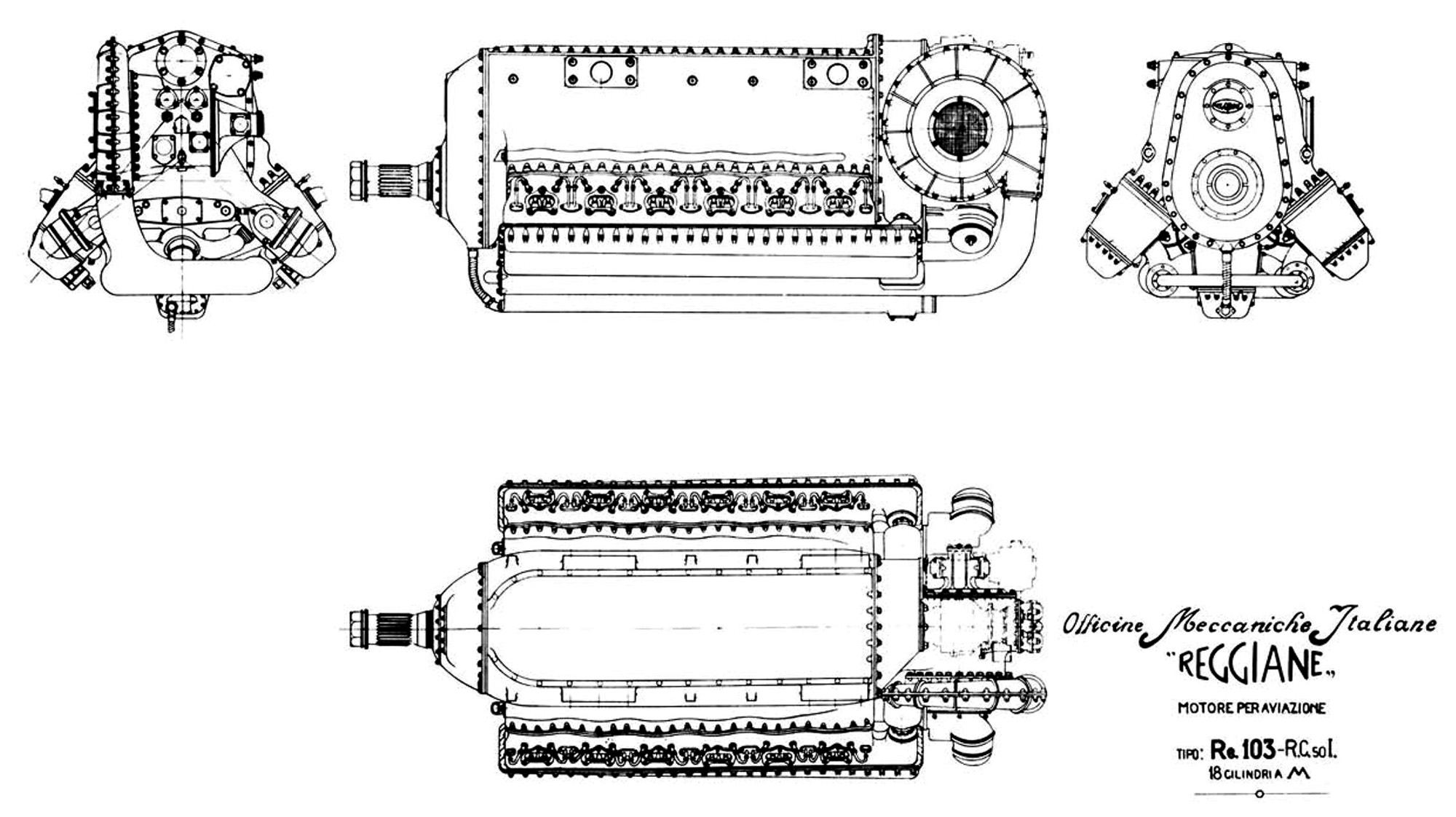
Undated three-view drawing of the Re 103 RC50 I engine. Note that it is listed as “18 Cilindri a M,” referring to its M-18 engine configuration.

In 1940, Reggiane focused on their next engine design, the Re 103. Like the Re 102 RC50 I, the Re 103 was an inverted W-18. However, with a bore of 5.51 in (140 mm), a stroke of 5.67 in (144 mm), and a total displacement of 2,435 cu in (39.9 L), the Re 103 was a larger engine than the Re 102 RC50 I. The Re 103 had a 6 to 1 compression ratio and a .511 propeller gear reduction. The engine was 91 in (2.33 m) long, 38 in (.97 m) wide, 36 in (.91 m) tall, and weighed 1,874 lb (850 kg). The Re 103 RC50 I was a candidate for the Reggiane RE 2005 fighter, along with a few other projects.

Although an independent design, the Reggiane Re 103 was in some ways similar to the Daimler-Benz DB 600 series engines. Both the DB 600 series engines and the Re 103 were inverted, had the supercharger impeller mounted parallel to the crankshaft on the upper left side of the engine, and featured fuel injection controlled by a module at the rear of the engine. Reggiane did have access to DB engines because licensed-built versions of the DB 601 (Alfa Romeo RA 1000 RC41 I) and DB 605 (FIAT RA 1050 RC58 I) were used in the RE 2001 and RE 2005 fighters respectively.

Reggiane Re 103 front-back 1943

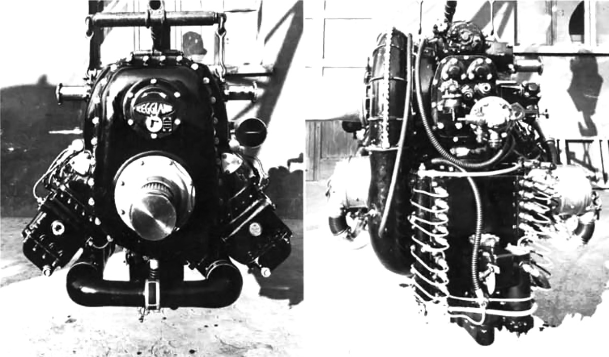
Front and rear of the Re 103 RC50 I engine. In the front view, note how the intake manifold feeds the individual cylinder banks. In the rear image, note the fuel injector distribution pump and the various fuel lines leading to each cylinder.

Air from the Re 103’s supercharger flowed through two manifolds positioned in between the engine’s cylinder banks. The left manifold supplied air to the left and center cylinder banks, while the right manifold provided air to the right cylinder bank. The manifolds met at the front of the engine, forming a loop. To keep frontal area to a minimum, the cylinder banks were positioned 40 degrees apart. Each cylinder had two intake and two exhaust valves. The valves were actuated by a single overhead camshaft. Each of the three camshafts (one for each cylinder bank) was driven by a vertical shaft at the rear of the engine. Also driven from the rear of the engine were the two magnetos that fired two spark plugs for each cylinder. The spark plugs were positioned on the outer side of the left and right cylinder banks and on the left side of the center cylinder bank. The fuel injectors were positioned on the inner side of the left and right cylinder banks and on the right side of the center cylinder bank.

Two versions of the Re 103 were initially proposed. The Re 103 RC50 I had a three-speed supercharger and was intended for fighter aircraft, while the Re 103 RC40 I had a two-speed supercharger and was intended for bombers. The supercharger was designed to automatically change speed according to the aircraft’s altitude. The Re 103 RC50 I used 100 octane fuel and produced 1,740 hp (1,298 kW) for takeoff at 2,840 rpm with 7.2 psi (.49 bar) boost and 1,600 hp (1,193 kW) at 16,400 ft (5,000 m) with 4.6 psi (.32 bar) boost. The Re 103 RC40 I used 87 octane fuel and produced 1,700 hp (1,298 kW) for takeoff at 2,840 rpm with 6.4 psi (.44 bar) boost and 1,500 hp (1,119 kW) at 13,123 ft (4,000 m) with 3.4 psi (.24 bar) boost.

Reggiane Re 103 left side 1943

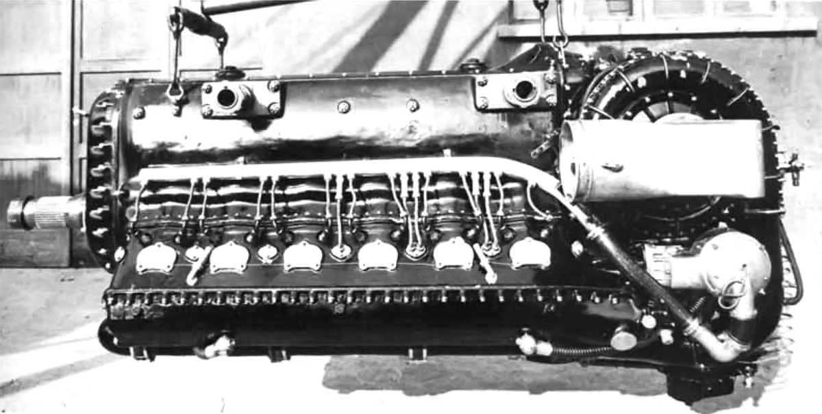
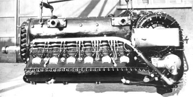
Left side of the Re 103 RC50 I engine displaying the supercharger mounted in a very similar manner as on the DB 600 series engines. Of course, no engine mounted cannon could be used on the W-18 Re 103 engine.

Three Reggiane Re 103 RC50 I engines were ordered by the Ministero dell’Aeronautica (Air Ministry) for the Regia Aeronautica (Royal Italian Air Force). A prototype Re 103 RC50 I was built by April 1942 and ran later that year. Development of the Re 103 inspired two additional and very similar engines, the Re 103 RC57 I and the Re 105 RC100 I. Both of these engines had the same configuration and displacement as the Re 103. The Re 103 RC57 I weighed 2,061 (935 kg), and its supercharger was optimized for 18,700 ft (5,700 m), where the engine produced 1,405 hp (1,048 kW). No orders were placed for the Re 103 RC57 I.

The Re 105 RC100 I engine had a two-stage supercharger and was optimized for 32,808 ft (10,000 m), at which altitude the engine produced 1,310 hp (977 kW). The two-stage supercharger was essentially made up of two separate superchargers. The first stage was located on the right side of the engine and mirrored the second stage, which was located in the original Re 103 supercharger position on the left side of the engine. Air flowed through a tube from the first stage, around the back of the engine, and into the inlet of the second stage. The Re 105 RC100 I weighed 1,984 lb (900 kg). Three Re 105 RC100 I engines were ordered in 1943.

Reggiane Re 103 right side 1943

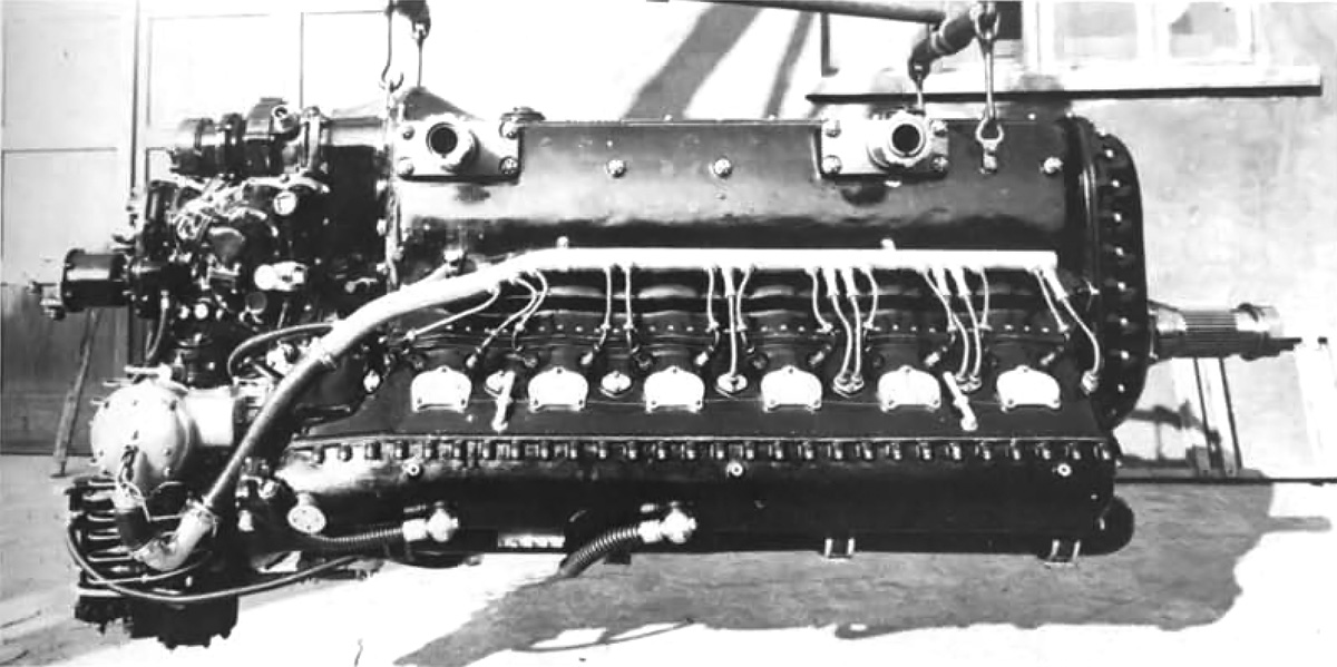
The complete Reggiane Re 103 RC50 I engine in October 1943. The 18-cylinder engine produced 1,740 hp (1,298 kW) for takeoff.

Three other engine designs were studied in 1941 while the Re 103 was being built. The Re 104 RC38 was the first, and it was a V-12 that produced 1,100 hp (820 kW) at sea level. The engine was derived from the Isotta Fraschini Asso L.121 RC40 but with a two-speed supercharger. The Re 104 RC38 had a 5.75 in (140 mm) bore and 5.67 in (160 mm) stroke. Its total displacement was 1,765 cu in (28.9 L), and the engine was intended as a possible alternative to the DB 601. No examples were built.

The second design study was for a 24-cylinder engine using four Re 103 cylinder banks in a horizontal H configuration. This design allowed many parts to be interchangeable with the Re 103 engines. Reggiane’s H-24 engine produced 2,200 hp (1,621 kW) at 19,685 ft (6,000 m). If the 24-cylinder engine had the same bore and stroke as the Re 103, it would have had a displacement of 3,247 cu in (53.2 L). The last engine under study was a two-stroke diesel of unknown specifics. The H-24 and the diesel did not progress beyond the initial design.

Reggiane Re 105 RC100 and H-24

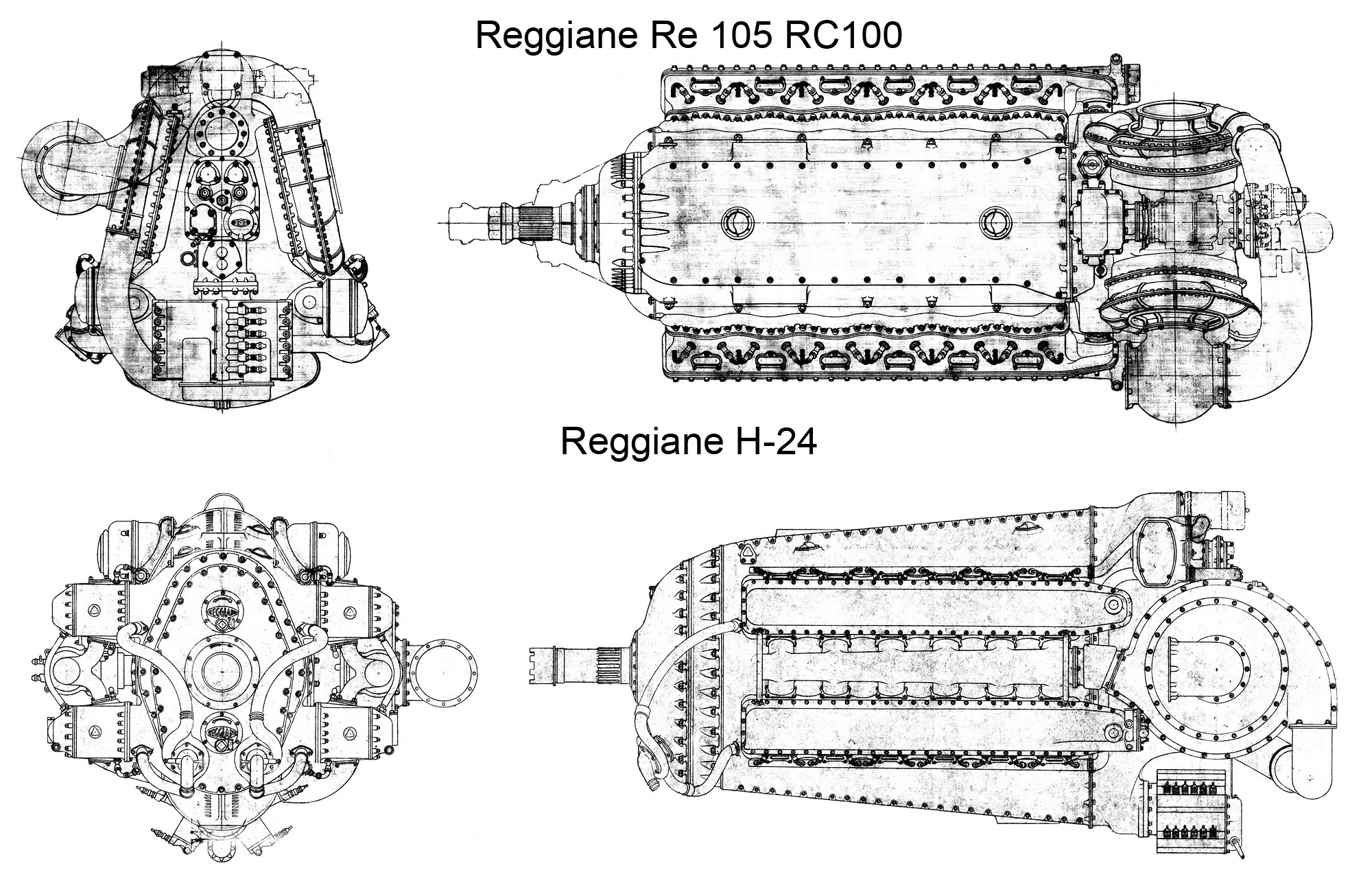
Top—rear and top views of the Re 105 RC100 engine. Note the two-stage supercharger arrangement. The outline around the front of the engine was for a proposed long gear reduction that added 6 in (.15 m) to the engine’s length. Bottom—front and side views of the H-24 engine. Note the crankshafts rotated clockwise (when viewed from the rear), and the propeller shaft rotated counterclockwise, just like the Re 103 and Re 105 engines.

At least two Re 103 engines were built, and most likely they were both Re 103 RC50 I engines, but development was slow. Construction had also begun on the Re 105 RC100 I. Italy’s surrender on 8 September 1943 brought an end to all of Reggiane’s engine programs. After the surrender, Reggiane’s northern factories were under German control and manufactured parts for the Daimler-Benz DB 605 and other engines. The Germans were not interested in the Re 103 or other Reggiane engines, and developmental activity was not continued.

*Italian aircraft engine naming convention varies by source. As an example, the punctuation, capitalization, and spacing of the Re 101 RC50 I designation can vary and still refer to the same engine, as in RE-101R.C.50 I or Re.L 101 R.C. 50 I.

Reggiane RE 2005

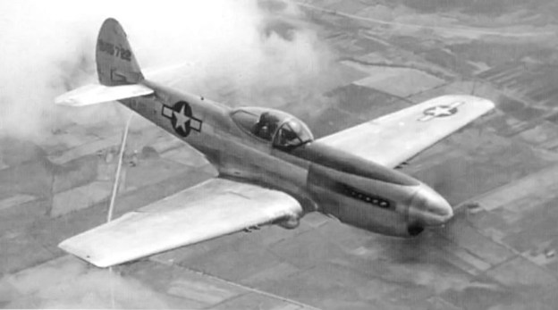
The Reggiane RE 2005 fighter was a potential candidate to be powered by the Re 103 engine. Only about 48 examples of the aircraft were built, and they were powered by the 1,475 hp (1,100 kW) FIAT RA 1050 RC58 I (licensed-built Daimler-Benz DB 605).

Sources:
I Reggiane dall’ A alla Z by Sergio Govi (1985)
– “I Motori Alle Reggiane” by Adriano and Paolo Riatti, Associazione Amici del Corni (March 2013)
The Caproni-Reggiane Fighters 1938-1945 by Piero Prato (1969)
https://it.wikipedia.org/wiki/Reggiane_RE_103
http://www.webalice.it/paolo.riatti/motori.html

Curtiss XP-40Q-2A flight

Curtiss XP-40Q Fighter

By William Pearce

Although not readily apparent at the time, Curtiss-Wright’s Airplane Division (Curtiss) was already in a state of decline at the start of World War II. The company’s final two truly successful aircraft, the P-40 Warhawk fighter and C-46 Commando transport, had already flown. While the Curtiss SB2C Helldiver carrier-based dive bomber would achieve some success toward the end of the war, its development was prolonged and plagued with issues, and the aircraft was never liked by its pilots and crews. Throughout the war years, Curtiss continually strove to develop world-beating aircraft but only managed to build one dead-end prototype after another. A brief glimmer of hope lay in the last model of the P-40, the P-40Q (Curtiss model 87X).

Curtiss XP-40Q-1

The Curtiss XP-40Q-1 (42-9987) with its standard canopy and sleek nose. Note the scoop for the engine air intake above the cowling.

XP-40Q development was initiated by 1943. The goal was to improve the P-40 to equal or surpass the performance of newer fighter aircraft. It was thought that the improved performance of the P-40Q would justify the aircraft entering production, and its similarities with P-40s then being produced would minimize tooling and production delays. In addition, there would be some part interchangeability with older P-40 aircraft, and current P-40 pilots and crews would be familiar with the new aircraft and its systems.

Three XP-40Q prototypes were built; their origins and histories have always been a point of disagreement between sources. All XP-40Qs were built up from other P-40 airframes. They all had only four .50-cal machine guns with 235 rpg. All of the XP-40Q aircraft were powered by two-stage supercharged Allison V-1710 engines and a four-blade propeller.

Curtiss XP-40Q-1 front

Another view of the XP-40Q-1. Note the radiators and oil coolers mounted in the wing center section.

The XP-40Q-1 was the first aircraft, and it was built in 1943 from a P-40K-10 (serial 42-9987) that had been damaged in a landing accident on 27 January 1943. The Q-1 was painted olive drab and had the standard P-40 wing and canopy. The nose of the aircraft was lengthened to accommodate the V-1710-101 (F27R) engine. At 3,200 rpm, the -101 engine produced 1,500 hp (1,119 kW) at 6,000 ft (1,829 m) and 1,325 hp (988 kW) for takeoff. The Q-1’s engine air intake was positioned above the cowling. The radiator and oil cooler were moved from the P-40’s iconic chin location to the wing center section, just below the fuselage (similar to the XP-40K). The XP-40Q-1 had a 37 ft 4 in (11.4 m) wingspan and was 35 ft 4 in long (10.8 m)—about 2 ft (.6 m) longer than a standard P-40.

The Q-1’s first flight reportedly occurred on 13 June 1943 from the Curtiss plant in Buffalo, New York. It is not clear if the aircraft suffered another accident, or if Curtiss was unhappy with its configuration and decided to modify it further. Regardless, by November 1943, the Q-1 had been modified and redesignated XP-40Q-2. The aircraft’s rear fuselage was cut down and a bubble canopy installed. Engine coolant radiators were positioned in the wings just outboard of the main gear. The oil cooler and engine air intake were relocated to the classic P-40 chin position, but the scoop was shallower and more elegant. The Q-2 retained the olive drab paint.

Curtiss XP-40Q-2

The Curtiss XP-40Q-2 (still 42-9987) after modification with a bubble canopy. The oil cooler and engine air intake have been relocated to the scoop under the engine. The coolant radiators have been moved outside of the main gear. The wings are still the standard P-40 wings, but they were later clipped by about one foot.

Still utilizing the -101 engine, the Q-2 was noted for having excellent visibility and handling. The aircraft had balanced controls and was very maneuverable, with a tight turn radius. Capt. Gustav Lundquist had evaluated the Q-2 and judged it to be the best P-40 he had flown; he recommended that further flight testing should be conducted. In December 1943, the Air Materiel Command recognized the XP-40Q-2’s performance and recommended that two additional prototypes be constructed.

Reportedly, the Q-2 was delivered to Eglin Field, Florida for testing in January 1944, but it was back at the Curtiss plant in Buffalo, New York in March for a series of flight tests. By this time, the Q-2 had its wingtips clipped about one foot each, and a V-1710-121 (F28R) engine was installed. The -121 produced 1,800 hp (1,342 kW) with water injection at 3,200 rpm up to 20,000 ft (6,096 m) and 1,425 hp (1,062 kW) for takeoff.

Curtiss XP-40Q-2A side

The XP-40Q-2A (42-45722) looking very much like the XP-40Q-2 but with clipped wings. This aircraft would change little throughout its existence.

A flight evaluation from April 1944 again noted the XP-40Q-2 as superior to all other P-40s and a very good aircraft overall. The XP-40Q-2 had a 35 ft 3 in (10.7 m) wingspan and was 35 ft 4 in (10.8 m) long. With full engine power at 3,000 rpm and water injection, the aircraft achieved 420 mph (676 km/h) at 15,000 ft (4,572 m) and had a maximum climb rate of 4,410 fpm (22.4 m/s) at 5,000 ft (1,524 m). At 3,200 rpm and with water injection, maximum speed was 422 mph (679 km/h) at 20,500 ft (6,248 m), and the climb rate increased by as much as 530 fpm (2.7 m/s) depending on altitude. However, the 3,200 rpm engine speed was only shown to offer an advantage between 12,000 and 33,000 ft (3,658 and 10,058 m). With just military power, the Q-2 recorded a speed of 407 mph (655 km/h) at 24,000 ft (7,315 m) and a climb rate of 3,210 fpm (16.3 m/s) at sea level. The aircraft could climb from sea level to 20,000 ft (6,096 m) in 4.8 minutes, 30,000 ft (9,144 m) in 8.9 minutes, and 39,000 ft (11,887 m) in 26.1 minutes. The Q-2’s service ceiling was 39,000 ft (11,887 m), and it had a gross weight of 9,000 lb (4,082 kg). The aircraft’s range was 700 miles (1,127 km).

The Q-2 was damaged when it nosed over after a test flight on 24 March 1944. The aircraft was repaired and then sent to Wright Field, Ohio in mid-1944. The aircraft was damaged again when it ground looped while landing on 31 July 1944. It is not clear if the aircraft was repaired or if the damage was too severe.

Curtiss XP-40Q-2A flight

This image of the XP-40Q-2A illustrates the clipped wings. Note the size of the bubble canopy and how to could be a bit smaller. The four .50-cal wing guns are easily seen. The XP-40Q was definitely a nice looking aircraft.

The next aircraft was the XP-40Q-2A. It was built from the initial P-40K-1 (serial 42-45722) that had been converted to the (unofficial) XP-40N. During the XP-40N conversion, the aircraft had a bubble canopy installed. This modification predated and served as the template for the bubble canopy that was installed on the Q-2.

The Q-2A was very similar to the final configuration of the Q-2—with a bubble canopy, clipped wings, and -121 engine. However, some modifications to the cockpit and canopy were made, and automatic radiator and oil cooler shutters were added. The Q-2A had a natural metal finish.

The Q-2A’s first flight occurred prior to the end of March 1944. The aircraft was plagued with engine trouble that resulted in a number of forced landings. The Q-2A spent most of its test time down for repairs. As a result, the Army Air Force (AAF) focused on the next aircraft, the Q-3, and loaned the Q-2A to Allison for engine tests. The Q-2A most likely had the same specifications and performance as the -121-powered Q-2.

The XP-40Q-3 was the last aircraft in the series. The Q-3 was built in early 1944 from a P-40N-25 (serial 43-24571) and was the only XP-40Q actually classified as such by the AAF. The aircraft was very similar to the XP-40Q-2A except for some refinements to the canopy and windscreen. The canopy was a bit smaller, and the flat windscreen was longer and more angled than the windscreen used on the preceding aircraft. Overall, the changes improved pilot visibility. The Q-3 had a -121 engine and a natural metal finish.

Curtiss XP-40Q-3 front

The last of the Curtiss P-40Qs: the XP-40Q-3 (43-24571). This aircraft later had anti-glare paint applied to the upper cowling, its serial number painted on the the tail, and “12” painted on the chin scoop. Note the radiator air inlets in the wings.

Delivered to AAF in April 1944, the Q-3 suffered an engine failure during an early test flight. The aircraft was moderately damaged in the subsequent forced landing. At this time, other aircraft with superior performance were available, and there was no AAF interest in repairing the Q-3 because there was no need for a P-40Q. It is doubtful that much performance testing was conducted on the Q-3, but the results should have been similar to those of the Q-2.

In March 1946, Allison still had the XP-40Q-2A (the second XP-40Q) when the AAF declared the aircraft as surplus. It is not clear if Allison purchased the aircraft and then later resold it or if it was sold as surplus directly from the AAF. Regardless, Joe Ziegler acquired the aircraft, and it was registered as NX300B. Given race number 82, the Q-2A was entered in the 1947 Thompson Trophy Race (run on 1 September 1947), but it did not qualify. Ziegler started the race anyway and was running in fourth place when the engine caught fire after just completing the 13th lap. Ziegler pulled up and off the course and bailed out of the Q-2A. Zeigler suffered a broken leg, and the Q-2A was destroyed.

Curtiss XP-40Q-3 side

This view of the XP-40Q-3 illustrates the revised canopy compared to the XP-40Q-2A. Note the oil cooler exit doors on the cowling just in front of the wing.

The story of the XP-40Q aircraft is a confusing one involving only three airframes but somewhere around eight designations and a number of different configurations. The P-40Q was one of the finest fighters Curtiss ever built, but the aircraft was two years or so too late. Its performance and capabilities were matched or exceeded by other aircraft already in service. Even if the P-40Q airframe had been ready two years earlier, the two-stage Allison engines would not have been ready, as they were still having developmental trouble in 1944. Sadly, the XP-40Q scenario was played out again and again as Curtiss tried to create another successful aircraft but only managed to produce aircraft that were ill-timed and outclassed.

Note: There is no indication that any of the XP-40Q aircraft used any type of a laminar flow wing. There is also no indication that any XP-40Q information was passed from Curtiss to North American Aviation (NAA) during the NA-73X’s (P-51’s) development. Not only are the two aircraft different in almost every way, there is no part of their separate developmental timelines that coincide. NAA did purchase some information from Curtiss at the request of the British government, but that information pertained to the XP-46 and arrived after the NA-73X was already designed.

Curtiss XP-40Q-2A Race 82

The XP-40Q-2A seen at Cleveland, Ohio for the Thompson Trophy Race in 1947. Other than some paint, including its registration and race number, the aircraft had changed little since its AAF days. It is truly unfortunate that the aircraft would soon be destroyed as a result of an engine fire.

Sources:
Curtiss Fighter Aircraft by Francis H. Dean and Dan Hagedorn (2007)
Vee is for Victory by Dan D. Whitney (1998)
U.S. Experimental & Prototype Aircraft Projects: Fighters 1939-1945 by Bill Norton (2008)
Memorandum Report on P-40Q Airplane, AAF No. 42-9987 by Capt. Gustav E. Lundquist (2 November 1943) via www.wwiiaircraftperformance.org (1.1 MB)
Flight Tests on the Curtiss XP-40Q-2, AAF No. 42-9987 by Lt Norman A. Krause (5 April 1944) via www.wwiiaircraftperformance.org (10.9 MB)