By William Pearce
In 1892, Hugo Junkers began experimental development of two-stroke, opposed-piston, gas engines. By 1910, Junkers had combined the opposed-piston principal with the diesel combustion cycle (compression ignition). Junkers investigated adapting this style of engine for aircraft use, but World War I and its aftermath prolonged development. In 1923, Junkers formed the Junkers Motorenbau (Jumo) to construct aircraft engines. Jumo’s first two-stroke, opposed-piston, diesel aircraft engine was commercially available in 1930. Originally known as the Jumo 4, the engine’s designation was changed in 1932 to Jumo 204.

The 24-cylinder Junkers Jumo 223 two-stroke, opposed-piston, diesel aircraft engine was one of the most unusual engines ever built. The engine’s coolant exit ports can be seen by the upper crankshaft. The two starters at the front of the engine engaged the propeller shaft.
Throughout the 1930s, Junkers developed a number of two-stroke, opposed-piston, diesel aircraft engines. There is no cylinder head on an opposed-piston engine. Rather, each cylinder has two pistons that move toward the center of the cylinder during the compression stroke. Ports in the cylinder wall allow the admission of air and expulsion of exhaust. These ports are covered and uncovered by the pistons as they move. The Junkers opposed-piston diesels were six-cylinder, inline engines with two crankshafts—one at the top of the engine and one at the bottom. Each crankshaft had a complete set of six pistons.
For installation in aircraft, there were practical limits to the Junker’s inline, opposed-piston engine configuration. Its double piston design made it a very tall engine, adding more cylinders to the Junkers diesels would have created a very long engine with a long crankshaft susceptible to torsional stresses. Increasing the engine’s bore and/or stroke would result in a larger engine with a lot of rotating mass, necessitating relatively low rpm. Engines capable of a continuous 2,000 hp (1,490 kW) output were needed for proposed large transoceanic aircraft, but an inline, opposed-piston aircraft engine able to produce 2,000 hp (1,490 kW) of continuous power was simply not feasible.

The Jumo 204 was the first diesel aircraft engine commercially available from Junkers. Its basic configuration was repeated in later Jumo diesels—collectively the most successful diesel aircraft engines produced.
By 1936, Junkers engineer Dr. Johannes Gasterstädt had come up with an opposed-piston engine configuration that would enable 2,000 hp (1,490 kW) in a compact package suitable for aircraft use. The configuration consisted of four cylinder banks positioned 90 degrees to each other so that they formed a rhombus—a square balanced on one point (◇). The pistons for two adjacent cylinder banks were connected to a crankshaft positioned at each corner of the rhombus. Each cylinder bank had six cylinders. The complete engine had four crankshafts, 24 cylinders, and 48 pistons.
Junkers’ rhombus-configured engine investigation was designated P2000. Dr. Gasterstädt passed away in 1937, and Prof. Otto Mader and Manfred Gerlach took over the P2000 project. By the end of 1937, a single cylinder test engine and a complete six-cylinder block had been built and run. In April 1938, the RLM (Reichsluftfahrtministerium or German Ministry of Aviation) redesignated the P2000 engine as the Jumo 223. By December 1939, a full-scale Jumo 223 engine was completed, and that engine was run-in by a dyno (the dyno turning the engine) in January 1940.
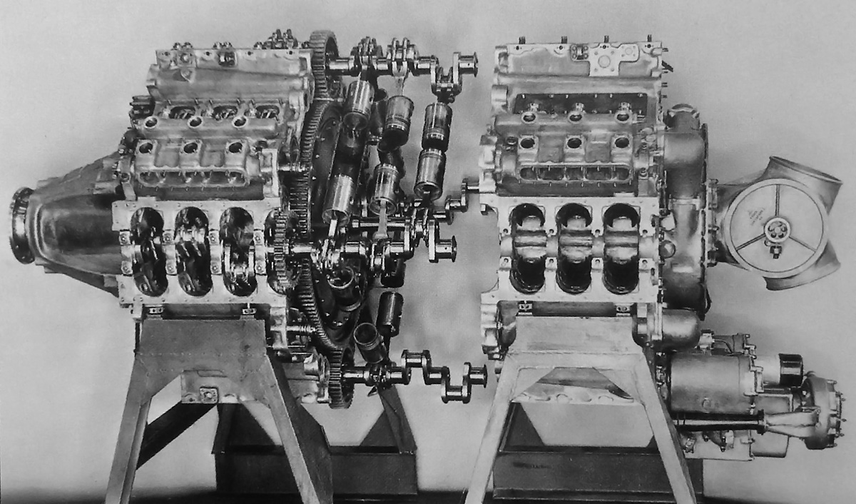
This picture of the separate castings that made up the Jumo 223 helps to illustrate the engine’s complexity. Note the scuffing and carbon deposits on the pistons, indicating they have been run.
The Jumo 223 was one of the most unusual engines ever built. The engine was constructed from two large and complex aluminum castings—one for the front of the engine and one for the rear. Each casting had four banks of three-cylinders. A large central gear was at the center of the engine where the two castings joined. Each crankshaft was made up of two main sections bolted together via a gear at its center. The gear on each crankshaft meshed with the central gear to transfer power from the crankshafts to the central gear. Drive shafts extended through the center of the engine from the front and rear of the central gear. The rear shaft powered the engine’s blower (weak supercharger) and accessories via a series of other gears. The front shaft led to the propeller. The central gear provided a .26 reduction in engine speed. At the front of the engine were two starters that engaged the propeller shaft to start the engine.

The Jumo 223’s central gear was powered by gears at the center of the engine’s four crankshafts. Note the fork-and-blade connecting rods.
The left and right crankshaft gears each drove separate camshafts for an upper and lower row of fuel injection pumps. These camshafts and the injection pumps were located near the left and right crankshafts. Cast directly under each row of injection pumps was a square port that ran along the engine. This port took air from the blower and delivered it to a small chamber around each steel cylinder liner. Air entered the cylinders via a series of holes around the cylinder liner’s circumference. The fuel injectors were located in the center of the cylinder. As the pistons moved toward each other, the intake holes were covered and the air was compressed. Diesel fuel was injected and ignited by the heat of compression. The expanding gases forced the pistons away from each other, uncovering the intake holes (for scavenging) and then the exhaust ports, which were located near the upper and lower crankshafts. Exhaust gases flowed out the ports in the cylinder liner into a small chamber surrounding the liner. The exhaust gases for each cylinder bank were collected by a manifold that led to a turbocharger at the rear of the engine. It is not clear if the turbocharger was ever tested, but there is one photo that shows a Jumo 223 with the turbocharger or a mockup of it. The pistons were connected to the crankshaft via fork-and-blade connecting rods. Each crankshaft was secured in the crankcase by eight main bearings.
A triangular port for coolant was cast on both sides of the engine near the upper and lower crankshafts. Coolant flowed from the coolant pump located on the bottom rear of the engine and into the lower triangular ports. The coolant circulated throughout the engine and exited near the upper crankshaft via the coolant ports at the front of the engine.
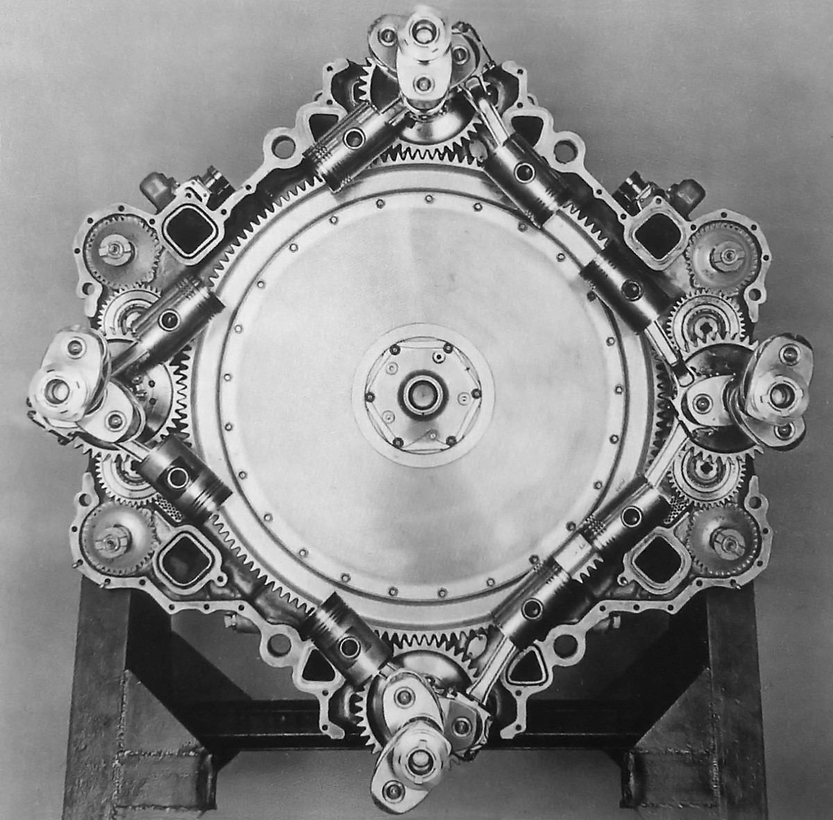
The central gear and front half of the engine is shown in this picture. Note the gears for the fuel injection pump camshafts by the left and right crankshafts. Coolant flowed through the triangular ports near the upper and lower crankshafts. Air flowed through the square ports near the left and right crankshafts.
The Jumo 223 engine had a 3.15 in (80 mm) bore and a 4.72 in (120 mm) stroke x 2 (for the two pistons per cylinder). Total displacement was 1,767 cu in (28.95 L). Without the propeller, the engine was 81.5 in (2.07 m) long, 48.8 in (1.24 m) wide, 53.0 in (1.345 m) tall, and weighed 3,086 lb (1,400 kg). The opposed pistons created a compression ratio of 17 to 1. With its planned intercooled turbocharger, the Jumo 223 was designed to produce 2,500 hp (1,860 kW) at an astonishing 4,400 rpm. That rpm would yield a fairly high average piston speed of 3,465 fpm (17.6 m/s). The Jumo 223 had a critical altitude rating of 1,800 hp (1,340 kW) at 16,404 ft (5,000 m) with the possibility of increasing the altitude to 32,808 ft (10,000 m) as the engine was further developed. Specific fuel consumption was .391 lb/hp/hr (238 g/kW/hr). The engine was contemplated for use in the four-engine Messerschmitt Me 264 long-range bomber, the six-engine Junkers EF100 commercial airliner, and other military aircraft projects.
The Jumo 223 engine ran for the first time on 27 February 1940. Without the turbocharger, the only boost came from the engine’s blower that was just intended to scavenge the cylinders. Peak high temperatures of 2,552 degrees F (1,400 degrees C) were encountered in the cylinders during combustion and caused pitting and seizure of the pistons. The issue was caused by the asymmetrical injection of fuel, a result of locating the injectors only on the outside of the engine, for ease of service, rather than having additional injectors inside the engine’s “square.”

The blower at the rear of the Jumo 223 can clearly be seen in this picture. The pipes leading away from the blower provided air to the passageways cast in the engine. The coolant pump is at the bottom of the engine.
Fuel injectors were modified, and tests continued throughout 1940. Three engines had been built by early 1941. In February 1941, the second engine was run for 100 hours and achieved a peak of 1,830 hp (1,360 kW) at 3,810 rpm. On 20 March 1941, the Jumo 223 passed the 2,000 hp (1,490 kW) mark by producing 2,040 hp (1,520 kW) at 3,980 rpm. During a 100 hour engine run in July 1941, crankshaft bolts and crankshafts were broken, indicating resonance vibration issues. In October 1941, the third engine completed a 100 hour test run at 1,500 hp (1,115 kW). The engine was run at a lower power because of the issues encountered when the Jumo 223 engine produced more power. The second engine was back in the test cell for a short run on 23 December 1941. The run set the mark for the highest power achieved by the Jumo 223 engine, producing 2,380 hp (1,770 kW) at 4,200 rpm.
Tests continued into 1942, but the engine’s reliability was a concern. The vibration issues seemed to be a result of the two-piece crankshafts and crankcase and the high rpm needed to produce the desired power. Along with the Jumo 223, Junkers was developing the Jumo 222—a 24-cylinder, spark ignition engine close to the same power and physical size as the Jumo 223, but lighter and of greater displacement. The Jumo 222 engine had more than its share of problems, and it made little sense to develop two engines in the same power class at the same time. In addition, developmental engines capable of more power than the Jumo 223 were needed.

This photo shows a Jumo 223 with a turbocharger. The exhaust manifolds can be seen leading to the turbocharger at the rear of the engine. Unfortunately, no information has been found regarding tests of this engine. It is possible that the turbocharger was only a mockup.
Development of the Jumo 223 as a production engine was halted in mid-1942. However, work on the engine continued, as it would serve as a model for a new, larger engine—the Jumo 224. By October 1942, six Jumo 223 engines were completed and two more were under construction. The eighth and last Jumo 223 prototype engine was run up to 2,200 hp (1,640 kW) on 28 February 1943. While this run was intended to be the last, Soviet forces had different ideas after the war. The Junkers factory was in Dessau, Germany and was part of the territory occupied by Soviet troops. The Soviets were interested in the Jumo 223 engine. The eighth example was run again on 23 March 1946 and for the last time on 4 April 1946. The last run was for a Soviet delegation and lasted 73 minutes. The run was halted after two pistons failed. Reportedly, at least one of the Junkers Jumo 223 engines was taken to State Factory No.500 in Tushino (now part of Moscow), Russia for further research, but no Jumo 223 engines are known to exist.
Note: There is no doubt that the Junkers Jumo opposed-piston engines in some way inspired the Napier Deltic, especially since Napier purchased licenses to build the Jumo 204 and 205 engines (to be built as the Culverin and Cutlass) in the 1930s. However, there is no indication that information on the Jumo 223 or 224 engines was applied to the design of the Deltic. In fact, the Deltic possessed many unique design characteristics, such as one crankshaft rotating the opposite direction compared to the other two.

The first Jumo 223 engine running on a test stand at the Junkers works in Dessau, Germany in early 1940.
Sources:
– Junkers Flugtriebwerke by Reinhard Müller (2006)
– Flugmotoren und Strahltriebwerke by Kyrill von Gersdorff, et. al. (2007)
– Opposed Piston Engines by Jean-Pierre Pirault and Martin Flint (2010)
– http://histomobile.com/dvd2.php?lien2=usa/tech/121-2.htm
– http://p-d-m.livejournal.com/28230.html