

By William Pearce
Under Junkers engineer Manfred Gerlach, development of the Junkers Motorenbau (Jumo) 224 two-stroke, opposed-piston, diesel aircraft engine began when the development of the Jumo 223 stopped in mid-1942. The Jumo 223 had encountered vibration issues as a result of its construction, and its maximum output of 2,500 hp (1,860 kW) fell short of what was then desired. More power was needed for the large, long-range aircraft on the drawing board.
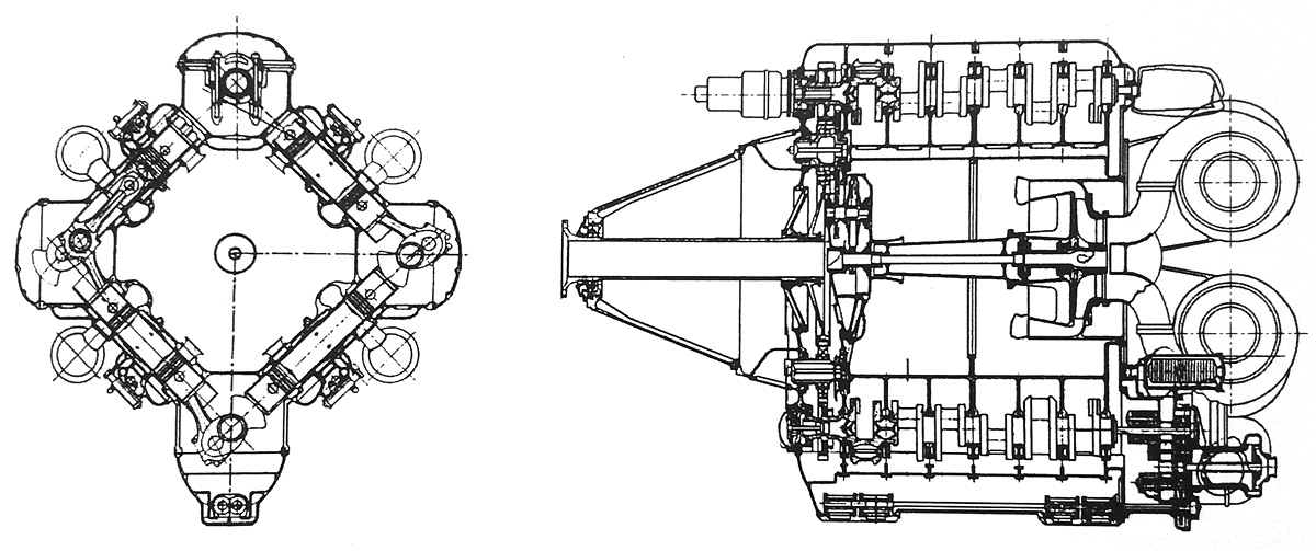
Front and side sectional views of the Junkers Jumo 224 engine. Note in the side view how the turbochargers feed the supercharger/blower mounted in the “square” of the engine. The front of the crankshafts engage gears for the propellers, supercharger, and fuel injection camshafts.
The Jumo 224 retained the same basic configuration as the Jumo 223, with four six-cylinder banks positioned 90 degrees to each other so that they formed a rhombus—a square balanced on one corner (◇). The pistons for two adjacent cylinder banks were attached to a crankshaft located at each corner of the rhombus. The complete engine had four crankshafts, 24 cylinders, and 48 pistons.
Like the Jumo 223, the Jumo 224 engine was constructed from two large and complex castings—one for the front of the engine and one for the rear. Each casting had four banks of three-cylinders. To enable the use of contra-rotating propellers, two gears were connected to the front of each crankshaft. The first gear was the bigger of the two and engaged a large central gear at the front and center of the engine. The outer propeller shaft was connected to the front of the central gear. Through an idler gear, the small gears on all the crankshafts drove a smaller central gear that was connected to the inner propeller shaft. However, the engine could be configured for use with a single propeller rotating in either direction. The central gears provided an engine speed reduction of .35.

Although never completed, the Jumo 224 would have closely resembled a larger version of the Jumo 223 shown above.
The upper and lower crankshafts also drove separate camshafts for the left and right rows of fuel injection pumps. These camshafts as well as the injection pumps were located near the upper and lower crankshafts. Through a series of step-up gears, the left and right crankshafts powered a drive shaft for the engine’s supercharger/blower, which was located in the rear “square” of the engine.
Exhaust gases from each cylinder bank were collected by a manifold that led to a turbocharger at the rear of the engine. Each of the four cylinder banks had its own turbocharger. After passing through the turbocharger, the air flowed into the supercharger where it was further pressurized, and then into the cylinders via a series of holes around the cylinder’s circumference. As the pistons moved toward each other, the intake holes were covered and the air was compressed. Diesel fuel was injected and ignited by the heat of compression. The expanding gases forced the pistons away from each other, uncovering the intake holes (for scavenging) and then the exhaust ports, which were located near the left and right crankshafts.
At its core, the Jumo 224 was four Jumo 207C inline, six-cylinder, opposed-piston engines combined in a compact package. Using the proven Jumo 207C as a starting point cut down the development time of the Jumo 224 engine. The Jumo 224 used the same bore and stroke as the Jumo 207C. While the Jumo 224 was being designed, a Jumo 207C was tested to its limits to better understand exactly what output could be expected from the Jumo 224. Tests conducted in late 1944 found that with a 200 rpm overspeed (3,200 rpm), intercooling, modified fuel injectors, and 80% methanol-water injection, the Jumo 207C was capable of a 10 minute output at 2,210 hp (1,645 kW)—twice its standard rating of 1,100 hp (820 kW).
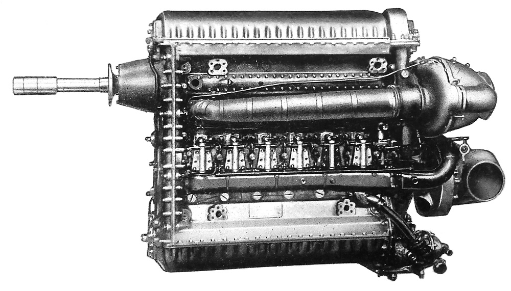
The Junkers Jumo 207C had an integral blower and turbocharger. The engine served as the foundation for the Jumo 224; its cylinder dimensions and various components were used.
The Jumo 224 had a bore of 4.13 in (105 mm) and a stroke of 6.30 in (160 mm) x 2 (for the two pistons per cylinder). Total displacement was 4,058 cu in (66.50 L). Without turbochargers, the engine was 111.4 in (2.83 m) long, 66.9 in (1.70 m) wide, 73.6 in (1.87 m) tall, and weighed 5,732 lb (2,600 kg). The opposed pistons created a compression ratio of 17 to 1. The planned output of the Jumo 224 was initially 4,400 hp (3,280 kW) at 3,000 rpm. However, many different combinations of intercooling, multiple-stage turbocharging, turbocompounding, and using exhaust thrust for up to 400 hp (300 kW) of extra power were proposed that gave the engine a variety of different outputs at critical altitudes up to 49,210 ft (15,000 m). Specific fuel consumption was estimated as .380 lb/hp/hr (231 g/kW/hr), and the engine’s average piston speed was 3,150 fpm (16.0 m/s) at 3,000 rpm.
From mid-1942 on, design work on the complex Jumo 224 moved ahead but often at a very slow pace. Developmental work on the 24-cylinder Jumo 222 and turbojet Jumo 004 engines took up all of the engineers’ time and Junkers Company resources, leaving little of either for the Jumo 224. The RLM (Reichsluftfahrtministerium or German Ministry of Aviation) was interested in the Jumo 224 engine for the six-engine Blohm & Voss BV 238 long-range flying boat, the eight-engine Dornier Do 214 long-range flying boat, and other post-war commercial and military aircraft projects. Even so, the RLM was more interested in the other Jumo engines, and they were given priority over the Jumo 224.

Gearing schematic of the Jumo 224 showing left and right propeller rotation. The drawing indicates the number of teeth (z) and their height (m) on each gear.
By October 1944, the Jumo 207D engine had proven itself reliable. This engine had a bore of 4.33 in (110mm)—.20 in (5 mm) more than the Jumo 207C. Thought was given to using Jumo 207D cylinders for the Jumo 224. This change would have increased the engine’s displacement by 396 cu in (6.5 L), resulting in a total displacement of 4,454 cu in (73.0 L). However, it is not clear if the larger bore was ever incorporated into the Jumo 224.
In November 1944 the RLM ordered the material for five Jumo 224 engines. At this stage in the war, with streams of Allied bombers overhead, it was nearly impossible for Junkers to find contractors able to produce the specialized components needed for the Jumo 224 engine. Even under ideal conditions, it would be years before the Jumo 224 engine would be ready for production. By the end of the war, the first Jumo 224 engine was around 70% complete. As Allied troops neared the Junkers factory in Dessau, Germany in late April 1945, almost all of the Jumo 224 plans, blueprints, and documents were destroyed to prevent the information from falling into the hands of the Allies.
After the Junkers plant was captured, the Jumo 207C that produced 2,210 hp was sent to the United States for study. The plant, Dessau, and all of eastern Germany was handed over to the Soviet Union. In March 1946, the Soviets expressed interest in the Jumo 224 (and 223) engine, and development continued in May 1946. Gerlach was still at the Junkers plant and continued to oversee the Jumo 224. However, building the engine in post-war, Soviet-occupied Germany proved to be more of a challenge than building the engine during the war. Jumo 224 development continued but at a very slow pace. In October 1946, Gerlach and a number of others were relocated to Tushino (now part of Moscow), Russia to continue work on the Jumo 224.
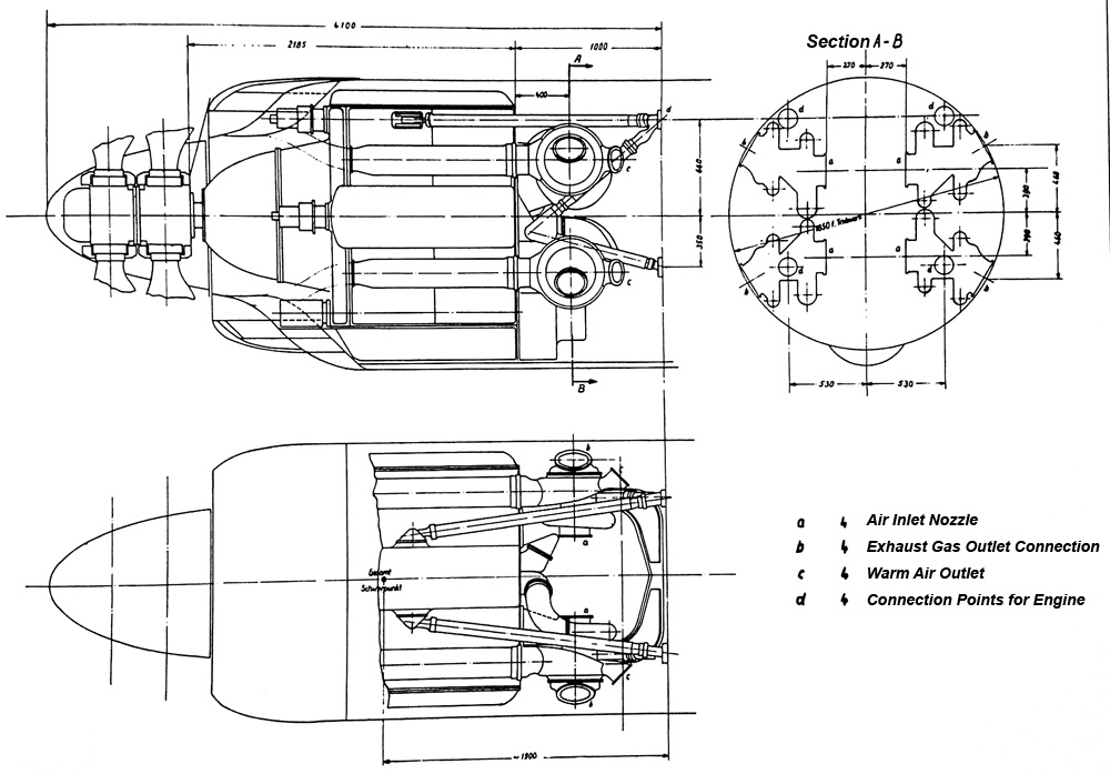
Installation drawing for the Jumo 224. Clearly seen are the four turbochargers and contra-rotating propellers. The inside cowling diameter is listed as 72.8 in (1.85 m).
Operating out of State Factory No. 500, the group was to continue development of the Jumo 224 engine, now designated M-224. The M-224 was turbocharged, 123.1 in (3.13 m) long, 66.9 in (1.70 m) wide, 74.7 in (1.90 m) tall, and weighed 6,063 lb (2,750 kg). Gerlach believed in the M-224 and did what he could to continue its development, but the Germans did not find themselves very welcome at the factory, and nearly everything they requested was slow in coming. To make matters worse, Jumo 224 parts and equipment that the Soviets had captured and sent from Dessau never arrived in Tushino.
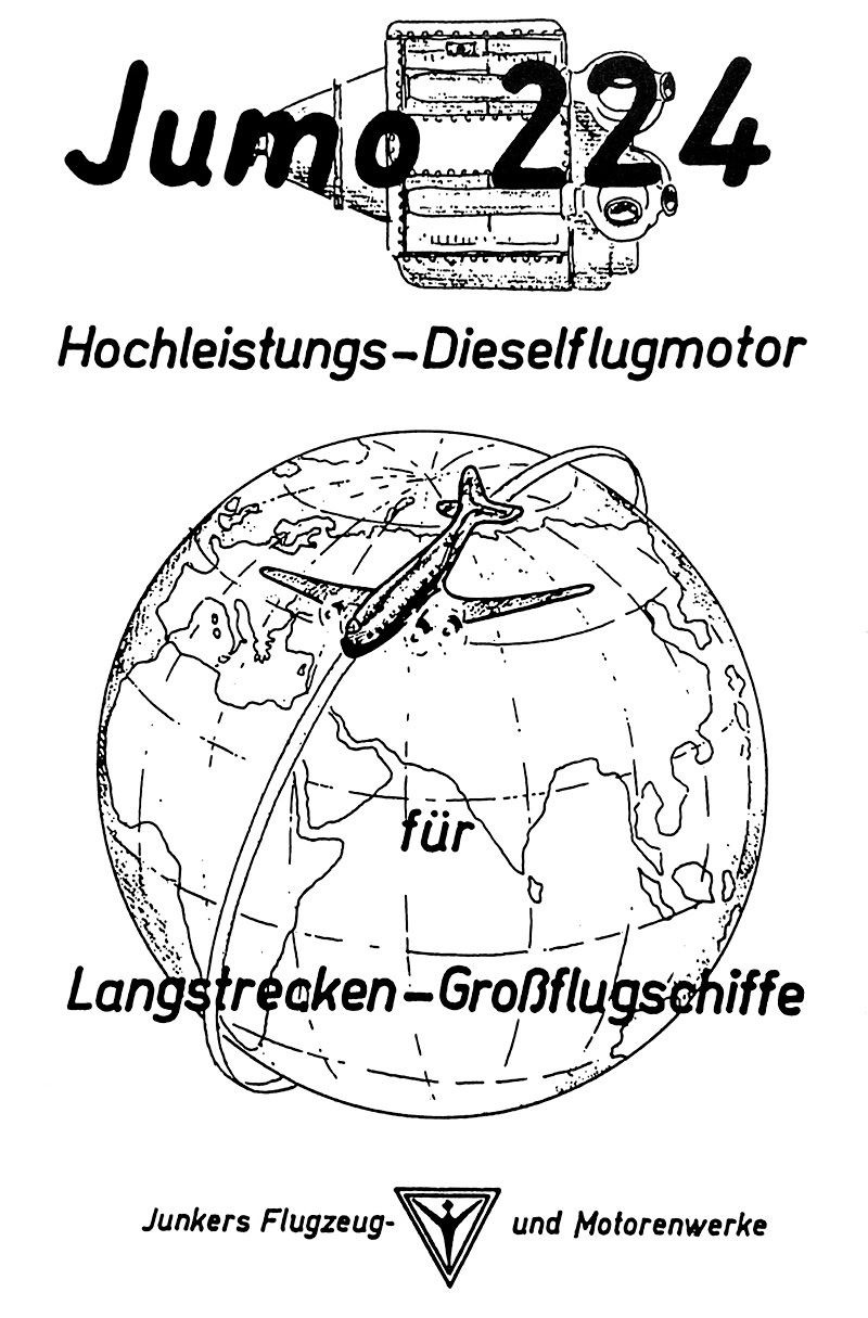
Junkers post-World War II advertisement for the Jumo 224 stating the high performance diesel aircraft engine was for large, long-distance aircraft.
Factory No. 500 was headed by Vladimir M. Yakovlev (no relation to the aircraft designer), who was hard at work on his own large diesel aircraft engine—the 6,200 hp (4,620 kW), 8,760 cu in (143.6 L), 42-cylinder M-501. Yakovlev was critical of the work done on the M-224; he felt that the engine took resources away from the M-501. With little progress on the M-224, Yakovlev was able to convince Soviet officials that his engine had the greater potential, and all development on the M-224 was stopped in mid-1948.
No parts or mockups of the Jumo 224 / M-224 are known to exist. The Yakovlev M-501 engine was run in 1952. The engine was not produced for aircraft, but it was built in the 1970s as the Zvezda M503 marine engine and is still used today for tractor pulling.
Sources:
– Junkers Flugtriebwerke by Reinhard Müller (2006)
– Flugmotoren und Strahltriebwerke by Kyrill von Gersdorff, et. al. (2007)
– Russian Piston Aero Engines by Vladimir Kotelnikov (2005)
– Opposed Piston Engines by Jean-Pierre Pirault and Martin Flint (2010)
– https://ru.wikipedia.org/wiki/%D0%9C-224

You did a great job on this good work.
Thank you!
TOTAL CRAZYNESS, what a complicated engine that Jumo was, no wonder the 224 never made it, probably some wagnerian delusions tipical of that nazi period.
Have there been any other engines that featured a turbocharger and a supercharger?
Hello Graham,
Actually, most turbocharged WWII engines were also supercharged. The US were the main users of turbos during WWII. In a way, the turbo was an accessory that could be added to the engine to enhance its performance, whereas the supercharger was typically an integral part of the engine. The V-1710 in the P-38, the R-2800 in the P-47, the R-1820 in the B-17, the R-1830 in the B-24, the R-3350 in the B-29 (etc) all had superchargers and turbochargers.
Regards,
Bill Pearce
Hi Bill,
I very much enjoy your writing on aircraft engines. However, I think we need to define the difference between “Supercharging” (a compressor mechanically driven from the engine, which compressed the fuel introduced into the engine via the inlet manifold), and “Turbocharging”, (A turbine driven by exhaust gases from the engine which, in turn, drove a compressor, which compressed the fuel introduced via the inlet manifold into the engine).
It is my understanding that all the American engines referred to in the letter above were turbocharged, not supercharged. The Rolls-Royce Merlin and Griffon, the Mercedes-Benz 601,603, 605, in fact that whole family of liquid cooled V12 engines, the Napier Sabre used supercharging, that is, the compressor was driven by a mechanical attachment from the engine itself.
Hello John,
First, thank you for your comments. Second, please let me know if my explanation does not make sense.
You are correct in that the American engines mentioned in the post above were typically referred to as turbocharged in the applications listed, but the engines also had an integral, mechanically-driven supercharger (that was typically single-speed). I think that the WWII-American perspective was that the turbocharger was an extra unit being added to the engine, making it “turbocharged.” The integral supercharger was not explicitly called out because it was standard and not anything extra.
For example, the V-1710 in a P-39 and a P-38 had a mechanically-driven supercharger, but the P-38 also had a turbocharger. The R-2800 in a Hellcat and a P-47 had a mechanically-driven supercharger, but the P-47 also had a turbocharger. The R-1820 in a DC-3 and a B-17 had a mechanically-driven supercharger, but the B-17 also had a turbocharger. The R-1830 in a PBY and a B-24 had a mechanically-driven supercharger, but the B-24 also had a turbocharger. The R-3350 in a Constellation and a B-29 had a mechanically-driven supercharger, but the B-29 also had a turbocharger.
For the P-38, P-47, B-17, B-24, B-29 (etc), air was compressed by the turbocharger, passed through an intercooler and the carburetor, then fed into the integral, engine-driven supercharger, and then delivered into the cylinders. The turbocharger provided one stage of supercharging, and the mechanically-driven supercharger provided another stage that further increased boost.
Well Bill,
My great apologies. I had, as you say, always read that these engines were turbocharged, supercharging not being mentioned in all the accounts that I had read. As you say, they were in effect, two stage supercharged. I’ve learned something new…
Hi Bill,
I remember at least one book (and more, I think) listed these engines as turbo-supercharged. I read the books a long time ago and at the time I was confused until seeing a diagram not too dissimilar to the one in your above posting.
The one that annoys me is the term inter-cooling being used where post-cooling was employed. I am pretty sure I saw this used in a manual for a late series RR Merlin! I know these Merlins had both inter-cooling and post cooling, but I could swear they were referring to the post-cooler. I will have to see if I can find a scanned copy of that manual to see if my memory is on the blink.
These days, I think the best thing is to use the term “charge air cooler”, you can confuse more people with that one
Mr .Pearce
Do you know if Junkers or anyone else explored 3 crank & bank arrangements for these motors?
I ask because the sweep volume ratios on paper cutout models I made decades ago, seemed to have an edge in greater expansion ratios than line or rombus configurations. Which typically result in higher thermal efficiency in this universe-I would expect no loss of low end torque on a blown compression ignition, that is the usual trade off on normal single piston configurations.
You may find it interesting to compare “your” idea to the Napier Deltic.
Original Junkers page:
http://www.hugojunkers.bplaced.net/junkers-jumo-224.html