
By William Pearce
Around 1930, Daimler-Benz* developed the F-2 engine, initially intended for aviation use. The F-2 was a 60 degree, supercharged, V-12 engine with individual cylinders and overhead camshafts. The engine had a 6.50 in (165 mm) bore and an 8.27 in (210 mm) stroke. The F-2’s total displacement was 3,288 cu in (53.88 L), and it had a compression ratio of 6.0 to 1. The engine produced 800 hp (597 kW) at 1,500 rpm and 1,000 hp (746 kW) at 1,700 rpm. The engine was available with either direct drive or a .51 gear reduction, and weighed around 1,725 lb (782 kg). It is unlikely that the Daimler-Benz F-2 powered any aircraft, but it was used in a few speed boats.
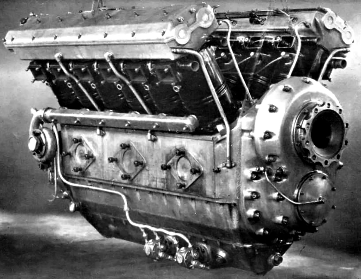
The Daimler-Benz OF-2 diesel engine was very similar to the spark ignition F-2. Note the dual overhead camshafts in the Elektron housing above the individual cylinders. This was one of the OF-2’s features that was not incorporated into the LOF-6.
In the early 1930s, Daimler-Benz used the F-2 to develop a diesel engine for airships. This diesel engine was designated OF-2 (O standing for Ölmotor, or oil engine), and it maintained the same basic V-12 configuration as the F-2. The individual cylinders were mounted on an Elektron (magnesium alloy) crankcase. Each cylinder had four valves that were actuated by dual overhead camshafts. The OF-2 had the same bore, stroke, and displacement as the F-2, but the OF-2’s compression ratio was increased to 15 to 1.
Fuel was injected into the cylinders at 1,330 psi (91.7 bar) via two, six-plunger injection pumps built by Bosch. The fuel was injected into a pre-combustion chamber located between the four valves in the cylinder head. This design had been used in automotive diesels built by Mercedes-Benz. Sources disagree on the gear reduction ratio, and it is possible that more than one ratio was offered. Listed ratios include .83, .67, and .58.
The Daimler-Benz OF-2 engine had a normal output of 700 hp (522 kW) at 1,675 rpm, a maximum output of 750 hp (559 kW) at 1,720 rpm, and it was capable of 800 hp (597 kW) at 1,790 rpm for very short periods of time. Fuel consumption at normal power was .392 lb/hp/hr (238 g/kW/hr). The engine was 74.0 in (1.88 m) long, 38.6 in (.98 m) wide, and 42.5 in (1.08 m) tall. The OF-2 weighed 2,061 lb (935 kg).
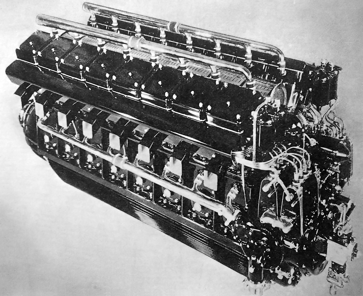
This view of a display-quality DB 602 engine shows the four Bosch fuel injection pumps at the rear of the engine. The individual valve covers for each cylinder can also be seen.
The OF-2 passed its type test in 1932. At the time, Germany was developing its latest line of airships, the LZ 129 Hindenburg and LZ 130 Graf Zeppelin II. These airships were larger than any previously built, and four OF-2 engines would not be able to provide sufficient power for either airship. As a result, Daimler-Benz began developing a new engine to power the airships in 1933. Daimler-Benz designated the new diesel engine LOF-6, but it was soon given the RLM (Reichsluftfahrtministerium or Germany Air Ministry) designation DB 602.
Designed by Arthur Berger, the Daimler-Benz DB 602 was built upon lessons learned from the OF-2, but it was a completely new engine. The simplest way to build a more powerful engine based on the OF-2 design was by adding two additional cylinders to each cylinder bank, which made the DB 602 a V-16 engine. The two banks of eight cylinders were positioned at 50 degrees. The 50 degree angle was selected over the 45 degree angle typically used for a V-16 engine. This gave the DB 602 an uneven firing order which helped avoid periodic vibrations.
The individual steel cylinders were mounted to the aluminum alloy crankcase. About a third of the cylinder was above the crankcase, and the remaining two-thirds protruded into the crankcase. This arrangement helped eliminate lateral movement of the cylinders and decreased vibrations. The crankcase was made of two pieces and split horizontally through the crankshaft plane. The lower part of the crankcase was finned to increase its rigidity and help cool the engine oil.

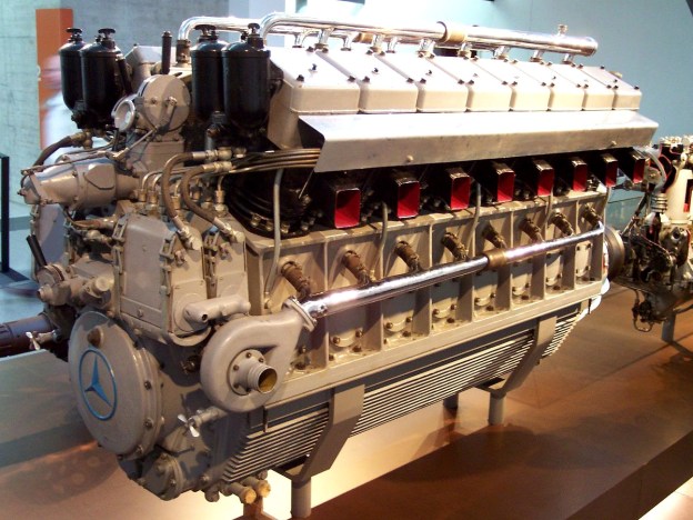
Originally called the LOF-6, the Daimler-Benz DB 602 was a large 16-cylinder diesel engine built to power the largest German airships. Note the three-pointed star emblems on the front valve covers. Propeller gear reduction was achieved through bevel planetary gears.
A single camshaft was located in the Vee of the engine. The camshaft had two sets of intake and exhaust lobes per cylinder. One set was for normal operation, and the other set was for running the engine in reverse. The fore and aft movement of the camshaft to engage and disengage reverse operation was pneumatically controlled. Separate pushrods for the intake and exhaust valves rode on the camshaft and acted on duplex rocker arms that actuated the valves. Each cylinder had two intake and two exhaust valves. Four Bosch fuel injection pumps were located at the rear of the engine and were geared to the camshaft. Each injection pump provided fuel at 1,600 psi (110.3 bar) to four cylinders. Fuel was injected into the center of the pre-combustion chamber, which was situated between the four valves. For slow idle (as low as 300 rpm), fuel was cut from one cylinder bank.
The DB 602 engine was not supercharged and had a .50 propeller gear reduction that used bevel planetary gears. The engine used fork-and-blade connecting rods that rode on roller bearings fitted to the crankshaft. The camshaft also used roller bearings, but the crankshaft was supported by plain bearings. Two water pumps were driven by a cross shaft at the rear of the engine. Each pump provided cooling water to one cylinder bank. The engine’s compression ratio was 16.0 to 1, and it was started with compressed air.
The DB 602 had a 6.89 in (175 mm) bore and a 9.06 in (230 mm) stroke, both larger than those of the OF-2. The engine displaced 5,401 cu in (88.51 L). Its maximum continuous output was 900 hp (671 kW) at 1,480 rpm, and it could produce 1,320 hp (984 kW) at 1,650 rpm for 5 minutes. The DB 602 was 105.9 in (2.69 m) long, 40.0 in (1.02 m) wide, and 53.0 in (1.35 m) tall. The engine weighed 4,409 lb (2,000 kg). Fuel consumption at cruising power was 0.37 lb/hp/hr (225 g/kW/hr).
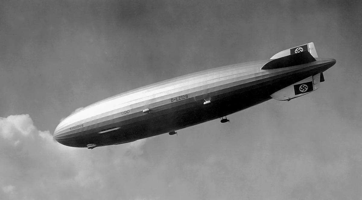
The ill-fated LZ 129 Hindenburg on a flight in 1936. The airship used four DB 602 engines housed in separate cars in a pusher configuration. Note the Olympic rings painted on the airship to celebrate the summer games that were held in Berlin.
Development of the DB 602 progressed well, and it completed two non-stop 150-hour endurance test runs. The runs proved the engine could operate for long periods at 900 hp (671 kW). Four engines were installed in both the LZ 129 Hindenburg and the LZ 130 Graf Zeppelin II. Each engine powered a two-stage compressor. Each compressor filled a 3,051 cu in (50 L) air tank to 850 psi (59 bar) that was used to start the engine and to manipulate the camshaft for engine reversing.
Plans for a water vapor recovery system that used the engines’ exhaust were never implemented, because the airships used hydrogen instead of the more expensive helium. The recovery system would have condensed vapor into water, and the collected water would have been used as ballast to help maintain the airship’s weight and enable the retention of helium. Without the system in place, expensive helium would have been vented to compensate for the airship steadily getting lighter as diesel fuel was consumed. With the United States unwilling to provide helium because of Germany’s aggression, the airships used inexpensive and volatile hydrogen, as it was readily available. The Hindenburg was launched on 4 March 1936, and the Graf Zeppelin II was launched on 14 September 1938.
Engines for the Hindenburg were mounted in a pusher configuration. In April 1936, the Hindenburg’s DB 602 engines experienced some mechanical issues on its first commercial passenger flight, which was to Rio de Janeiro, Brazil. The engines were rebuilt following the airship’s return to Germany, and no further issues were encountered. The Hindenburg tragically and famously burst into flames on 6 May 1937 while landing at Lakehurst, New Jersey.

Front view of the DB 602 engine in the Musée de l’Air et de l’Espace, in Le Bourget, France. Above the engine are the cooling water outlet pipes. In the Vee of the engine is the induction manifold, and the pushrod tubes for the front cylinders can be seen. Note the finning on the bottom half of the crankcase. (Stephen Shakland image via flickr.com)
The Graf Zeppelin II was still being built when the Hindenburg disaster occurred. Design changes were made to the Graf Zeppelin II that included mounting the DB 602 engines in a tractor configuration. The inability of Germany to obtain helium, the start of World War II, and the end of the airship era meant the Graf Zeppelin II would not be used for commercial travel. The airship was broken up in April 1940.
The DB 602 engine proved to be an outstanding and reliable power plant. However, its capabilities will forever be overshadowed by the Hindenburg disaster. Two DB 602 engines still exist and are on display; one is in the Zeppelin Museum in Friedrichshafen, Germany, and the other is in the Musée de l’Air et de l’Espace, in Le Bourget, France. Although the DB 602 was not used on a wide scale, it did serve as the basis for the Mercedes-Benz 500 series marine engines that powered a variety of fast attack boats (Schnellboot) during World War II.
*Daimler-Benz was formed in 1926 with the merger of Daimler Motoren Gesellschaft and Benz & Cie. Prior to their merger, both companies produced aircraft engines under the respective names Mercedes and Benz. After the merger, the Daimler-Benz name was used mostly for aircraft engines, and the Mercedes-Benz name was used mostly for automobiles. However, both names were occasionally applied to aircraft engines in the 1930s.

Rear view of the DB 602 engine on display in the Zeppelin Museum in Friedrichshafen, Germany. A water pump on each side of the engine provided cooling water to a bank of cylinders. (Stahlkocher image via Wikimedia Commons)
Sources:
– Aircraft Diesels by Paul H Wilkinson (1940)
– Aerosphere 1939 by Glenn D. Angle (1940)
– Diesel Engines by B. J. von Bongart (1938)
– High Speed Diesel Engines by Arthur W. Judge (1941)
– Diesel Aviation Engines by Paul H Wilkinson (1942)
– “The Hindenburg’s New Diesels” Flight (26 March 1936)
– “The L.Z.129’s Power Units” Flight (2 January 1936)
– https://en.wikipedia.org/wiki/LZ_129_Hindenburg
– https://en.wikipedia.org/wiki/LZ_130_Graf_Zeppelin_II


